EP2541339A2 - Fixing device and image forming apparatus employing same - Google Patents
Fixing device and image forming apparatus employing same Download PDFInfo
- Publication number
- EP2541339A2 EP2541339A2 EP12171711A EP12171711A EP2541339A2 EP 2541339 A2 EP2541339 A2 EP 2541339A2 EP 12171711 A EP12171711 A EP 12171711A EP 12171711 A EP12171711 A EP 12171711A EP 2541339 A2 EP2541339 A2 EP 2541339A2
- Authority
- EP
- European Patent Office
- Prior art keywords
- movement
- fixing device
- operation lever
- fixing
- nip
- Prior art date
- Legal status (The legal status is an assumption and is not a legal conclusion. Google has not performed a legal analysis and makes no representation as to the accuracy of the status listed.)
- Granted
Links
- 230000007246 mechanism Effects 0.000 claims description 40
- 238000012546 transfer Methods 0.000 description 48
- 238000001514 detection method Methods 0.000 description 14
- 239000010410 layer Substances 0.000 description 11
- 239000002344 surface layer Substances 0.000 description 11
- 238000000034 method Methods 0.000 description 10
- 230000008569 process Effects 0.000 description 10
- 238000004140 cleaning Methods 0.000 description 7
- YCKRFDGAMUMZLT-UHFFFAOYSA-N Fluorine atom Chemical compound [F] YCKRFDGAMUMZLT-UHFFFAOYSA-N 0.000 description 6
- 229910052731 fluorine Inorganic materials 0.000 description 6
- 239000011737 fluorine Substances 0.000 description 6
- 238000010586 diagram Methods 0.000 description 5
- 230000000694 effects Effects 0.000 description 5
- 239000002699 waste material Substances 0.000 description 5
- 230000007423 decrease Effects 0.000 description 4
- 230000003247 decreasing effect Effects 0.000 description 4
- 229920001971 elastomer Polymers 0.000 description 3
- 230000001965 increasing effect Effects 0.000 description 3
- 230000004048 modification Effects 0.000 description 3
- 238000012986 modification Methods 0.000 description 3
- 239000011347 resin Substances 0.000 description 3
- 229920005989 resin Polymers 0.000 description 3
- 239000005060 rubber Substances 0.000 description 3
- 229920002379 silicone rubber Polymers 0.000 description 3
- 239000004945 silicone rubber Substances 0.000 description 3
- 229910000975 Carbon steel Inorganic materials 0.000 description 2
- 239000010962 carbon steel Substances 0.000 description 2
- 230000008859 change Effects 0.000 description 2
- 230000005684 electric field Effects 0.000 description 2
- 230000004907 flux Effects 0.000 description 2
- 229910052751 metal Inorganic materials 0.000 description 2
- 239000002184 metal Substances 0.000 description 2
- 239000000758 substrate Substances 0.000 description 2
- 238000011144 upstream manufacturing Methods 0.000 description 2
- 230000037303 wrinkles Effects 0.000 description 2
- 230000002159 abnormal effect Effects 0.000 description 1
- 230000004308 accommodation Effects 0.000 description 1
- 229910052782 aluminium Inorganic materials 0.000 description 1
- XAGFODPZIPBFFR-UHFFFAOYSA-N aluminium Chemical compound [Al] XAGFODPZIPBFFR-UHFFFAOYSA-N 0.000 description 1
- 230000005540 biological transmission Effects 0.000 description 1
- 230000006835 compression Effects 0.000 description 1
- 238000007906 compression Methods 0.000 description 1
- 238000013461 design Methods 0.000 description 1
- 238000011161 development Methods 0.000 description 1
- 230000005674 electromagnetic induction Effects 0.000 description 1
- 230000002708 enhancing effect Effects 0.000 description 1
- 239000006260 foam Substances 0.000 description 1
- 229910052736 halogen Inorganic materials 0.000 description 1
- 150000002367 halogens Chemical class 0.000 description 1
- 238000010438 heat treatment Methods 0.000 description 1
- 239000000463 material Substances 0.000 description 1
- 230000010355 oscillation Effects 0.000 description 1
- 239000002245 particle Substances 0.000 description 1
- 230000002265 prevention Effects 0.000 description 1
- 230000008961 swelling Effects 0.000 description 1
- 229920003051 synthetic elastomer Polymers 0.000 description 1
- 239000005061 synthetic rubber Substances 0.000 description 1
- 238000012800 visualization Methods 0.000 description 1
Images






Classifications
-
- G—PHYSICS
- G03—PHOTOGRAPHY; CINEMATOGRAPHY; ANALOGOUS TECHNIQUES USING WAVES OTHER THAN OPTICAL WAVES; ELECTROGRAPHY; HOLOGRAPHY
- G03G—ELECTROGRAPHY; ELECTROPHOTOGRAPHY; MAGNETOGRAPHY
- G03G15/00—Apparatus for electrographic processes using a charge pattern
- G03G15/20—Apparatus for electrographic processes using a charge pattern for fixing, e.g. by using heat
- G03G15/2003—Apparatus for electrographic processes using a charge pattern for fixing, e.g. by using heat using heat
- G03G15/2014—Apparatus for electrographic processes using a charge pattern for fixing, e.g. by using heat using heat using contact heat
- G03G15/2017—Structural details of the fixing unit in general, e.g. cooling means, heat shielding means
- G03G15/2032—Retractable heating or pressure unit
-
- G—PHYSICS
- G03—PHOTOGRAPHY; CINEMATOGRAPHY; ANALOGOUS TECHNIQUES USING WAVES OTHER THAN OPTICAL WAVES; ELECTROGRAPHY; HOLOGRAPHY
- G03G—ELECTROGRAPHY; ELECTROPHOTOGRAPHY; MAGNETOGRAPHY
- G03G15/00—Apparatus for electrographic processes using a charge pattern
- G03G15/20—Apparatus for electrographic processes using a charge pattern for fixing, e.g. by using heat
- G03G15/2003—Apparatus for electrographic processes using a charge pattern for fixing, e.g. by using heat using heat
- G03G15/2014—Apparatus for electrographic processes using a charge pattern for fixing, e.g. by using heat using heat using contact heat
- G03G15/2017—Structural details of the fixing unit in general, e.g. cooling means, heat shielding means
- G03G15/2028—Structural details of the fixing unit in general, e.g. cooling means, heat shielding means with means for handling the copy material in the fixing nip, e.g. introduction guides, stripping means
Definitions
- This invention relates to an image forming apparatus, such as a printer, a copier, a facsimile machine, etc., utilizing an electro-photographic system, and a fixing device employed in the image forming apparatus.
- a thermal fixing unit is adopted in an image forming apparatus that employs an electro-photographic system or the like to apply heat and fix a toner image transferred onto a recording sheet transfer medium.
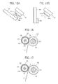
- the fixing unit executing such thermal fixing includes a fixing roller 121 as a fixing member and an opposed pressing roller 122 as a pressing member that presses against the fixing roller 121, as shown in Figures 16 and 17 .
- the fixing roller 121 and the pressing roller 122 are pressed against each other by a spring, not shown, and collectively form a fixing nip N between the fixing roller 121 and the pressing roller 122.
- a plain paper sheet and an envelope or the like are sometimes used in the fixing device as a transfer medium P, although the latter gets creased or wrinkled when it goes through the fixing nip.
- the size of the fixing nip N is increased when conveying a plain paper sheet through the fixing nip N as shown in Figure 16 , thereby increasing the pressure of contact or fixing pressure between the two rollers.
- the fixing pressure generated between the fixing roller 121 and the pressing roller 122 is decreased when the envelope passes between the fixing roller 121 and the pressing roller 122as shown Figure 17 .
- the size of the fixing nip N is decreased in this way to avoid readily wrinkling the envelope passing through the fixing nip N.
- a cam mechanism is generally used, as described below.
- a pressing roller is supported by a lever while an arm is disposed near the lever with its center being pivotally supported.
- a spring is arranged between one end of the arm and a base end of the lever lifting the base end.
- a cam mechanism engages the other end of the arm.
- a thermal fixing unit is adopted in an image forming apparatus that employs an electro-photographic system or the like to apply heat and fix a toner image transferred onto a recording sheet as a transfer medium.
- the fixing unit executing such thermal fixing includes a fixing roller 121 as a fixing member and a pressing roller 122 as a pressing member as shown in Figures 16 and 17 .
- the fixing roller 121 and the pressing roller 122 are pressed against each other by a spring, not shown, and collectively form a fixing nip N therebetween.
- a plain paper sheet and an envelope or the like are sometimes used in the fixing device as a transfer medium P.
- the envelope is formed by folding and partially pasting a sheet together, wrinkle and distortion appear thereon when it goes through the fixing nip.
- a range of the fixing nip N is increased when conveying the plain paper sheet therethrough as shown in Figure 16 .
- a contact pressure i.e., a fixing pressure
- a cam mechanism is generally used in the conventional image forming apparatus as described in the below described Japanese Patent Application Publications.
- a pressing roller is supported by a lever while an arm is disposed near the lever with its center being pivotally supported.
- a spring is arranged between one end of the ann and a base end of the lever lifting the base end. Further, a cam mechanism engages the other end of the arm.
- an adjustment mechanism is also included to adjust the pressure applied to the nip.
- a cam is provided as the adjustment mechanism, to act on a pressure applying mechanism.
- JP-22009-13968-A pressure applied by the pressing roller is similarly adjusted by rotating a cam.
- a sensor is provided in such a system to detect the position of the cam, such that a user can ascertain the state of the pressing roller by detecting the position of the cam.
- JP- H05-19712-A and JP- 2009-244514-A can adjust the nip pressure between the rollers, they cannot detect if the nip pressure is at a prescribed level.
- the system of JP- H05-19712-A requires space and an extra transmission assembly, such as a motor (e.g., a stepping motor), a worm gear, and a worm wheel, etc., to rotate the cam. This leads to a complex system that increases the overall size and cost of the apparatus.
- a motor e.g., a stepping motor
- a worm gear e.g., a worm gear
- a worm wheel e.g., a worm wheel
- JP-2009-13968-A although one of a normal pressure applying mode and a reduced pressure applying mode can be detected, this capability is provided at the price of an increase in the complexity and thus the overall size and cost of the apparatus.
- the present invention provides a novel fixing device that comprises a pair of rollers arranged in parallel to each other forming a fixing nip (N) therebetween and a nip pressure adjusting units.
- the nip pressure adjusting unit includes a pair of first and second operation levers disposed near respective widthwise ends of the pair of rollers, a first movement member cooperating with the first operation lever to perform a first movement, and a second movement member cooperating with the second operation lever to perform a second movement.
- a detector is provided to detect an event that both of the first and second movements are performed.
- a nip pressure adjusting unit adjusts a nip pressure generated in the fixing nip (N) by moving the pair of operation levers.
- the first movement is a linear movement
- the second movement is a swinging movement
- a direction of the linear movement and a swinging axis of the swinging movement is either parallel or orthogonal to each other.
- first operation lever and the first movement member are linked together via a first linking mechanism and the first linking mechanism converts a movement of the first operation lever into the first movement.
- the second operation lever and the second movement member are linked together via a second linking mechanism, and the second linking mechanism converts a movement of the second operation lever into the second movement.
- a returning member is provided to return the first linking mechanism and the first operation lever back to their initial positions.
- the first movement member is independently movable from the movement of the second operation lever when driven by the first operation lever via the first linking mechanism.
- the detector is a non-contact type sensor.
- the detector is a contact type sensor.
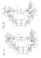
- Figure 1A is a schematic plan view of a fixing device in a high pressure contact state according to a first embodiment of the present invention
- Figure 1B is a schematic plan view of the fixing device in a low pressure contact state according to a first embodiment of the present invention
- Figure 2A is a schematic front view of the fixing device of Figure 1A in a high pressure contact state
- Figure 2B is a schematic front view of the fixing device of Figure 1A in a low pressure contact state
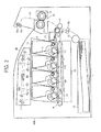
- Figure 3 is a diagram illustrating an overall configuration of an image forming apparatus employing the fixing device of Figures 1A and 1B ;
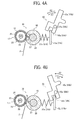
- Figure 4A is a cross-sectional view of a fixing roller and a pressing roller included in the fixing device in the high pressure contact state;
- Figure 4B is a cross-sectional view of a fixing roller and a pressing roller included in the fixing device in the low pressure contact state;
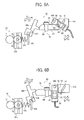
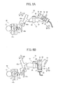
- Figure 5A is a schematic plan view of the fixing device in a high pressure contact state according to a second embodiment
- Figure 5B is a schematic plan view of the fixing device in a low pressure contact state according to a second embodiment
- Figure 6A is a schematic front view of the fixing device of Figure 5A in the high pressure contact state
- Figure 6B is a schematic front view of the fixing device of Figure 5B in the low pressure contact state
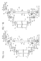
- Figure 7A is a schematic plan view of the fixing device in a high pressure contact state according to a third embodiment.
- Figure 7B is a schematic plan view of the fixing device in a low pressure contact state according to a third embodiment
- Figure 8A is a schematic front view of the fixing device of Figure 7A in the high pressure contact state
- Figure 8B is a schematic front view of the fixing device of Figure 7B in the low pressure contact state
- Figure 9A is a schematic plan view of the fixing device in a high pressure contact state according to a fourth embodiment
- Figure 9B is a schematic plan view of the fixing device in a low pressure contact state according to a fourth embodiment
- Figure 10A is a schematic plan view of the fixing device in a high pressure contact state according to a fifth embodiment
- Figure 10B is a schematic plan view of the fixing device in a low pressure contact state according to a fifth embodiment
- Figure 11A is a schematic plan view of the fixing device in a high pressure contact state according to a sixth embodiment
- Figure 11B is a schematic plan view of the fixing device in a low pressure contact state according to a sixth embodiment
- Figure 12 is a schematic view illustrating an essential part of a fixing device employing a contact-type sensor as a detector
- Figure 13A is a schematic diagram illustrating the contact-type sensor of Figure 12 in a detection status
- Figure 13B is a schematic diagram illustrating the contact-type sensor of Figure 12 in a non-detection status
- Figure 14 is a schematic view illustrating an essential part of a fixing device employing a non-contact type sensor as a detector
- Figure 15A is a schematic diagram illustrating the non-contact sensor of Figure 14 in a detection status
- Figure 15B is a schematic diagram illustrating the non-contact sensor of Figure 14 in a non-detection status
- Figure 16 schematically illustrates a conventional fixing device in a high pressure contact state
- Figure 17 schematically illustrates the conventional fixing device in a low pressure contact state.
- the image forming apparatus includes four process units 1Y, 1C, 1M, and 1BK. Each of the process units 1Y, 1C, 1M, and 1BK is detachably attached to a main body 100 of the image forming apparatus.
- Each of the process units 1Y, 1C, 1M, and 1BK has a similar configuration, but accommodates toner particles of a different color of yellow, cyan, magenta, or black corresponding to a color resolution component of a color image. Therefore, a configuration of the process unit 1Y is typically described herein below.
- the process unit 1Y has a photosensitive member 2 as an image bearer, a charge roller 3 to charge a surface of the photosensitive member 2 as a charging device, a development device 4 to generate a toner image on a surface of the photosensitive member 2, and a photoconductor cleaning blade 5 to clean the surface of the photosensitive member 2 as a photoconductor cleaning device.
- an exposure device 7 is disposed to expose a surface of the photoconductor 2.
- an intermediate transfer unit 6 is arranged below each of the process units 1Y, 1C, 1M, and 1BK.
- the intermediate transfer unit 6 has an intermediate transfer belt 10 mainly composed of an endless belt.
- the intermediate transfer belt 10 is stretched by a driving roller 8 and a driven roller 9 and is enabled to circulate around these rollers running in a direction as shown by an arrow in the drawing.
- each of the primary transfer rollers 11Y, 11C, 11M, and 11BK is pressed against the inner surface of the intermediate transfer belt 10 at a position facing the photoconductor 2. With such pressure contact, each of the photoconductors 2 is pressed against an outer surface of the intermediate transfer belt 10, thereby forming a primary transfer nip thereon.
- a secondary transfer roller 12 is disposed as a secondary transfer device at a position facing the driving roller 8 that stretches the intermediate transfer belt 10.
- the secondary transfer roller 12 is pressed against of the outer surface of the intermediate transfer belt 10, thereby forming a secondary transfer nip thereon.
- the intermediate transfer unit 6 is provided with a belt cleaning unit 21 for cleaning the surface of the intermediate transfer belt 10. Further, below the intermediate transfer unit 6, a waste toner container 22 is disposed to accommodate waste toner. Even not illustrated, a waste toner transfer hose is provided extending from the belt cleaning device 21 and connected to an entrance of the waste toner container 22.
- a recording medium container 13 is disposed to accommodate recording media P, such as a recording sheet, an OHP (Over Head Projector) sheet, etc.
- a sheet supply roller 14 or the like is provided in the recording medium container 13 to launch the recording medium P therefrom.
- a transportation path R1 is disposed in the main body 100 of the image forming apparatus to guide the recording medium P upward from the recording medium container 13.
- a pair of registration rollers 15a and 15b is disposed on an upstream conveyance path R1 (see a bottom in the drawing) from the secondary transfer nip formed between the driving roller 8 and the secondary transfer roller 12 in a transport direction.
- a fixing device 16 is also disposed on a downstream transportation path R1 (see an upper side in the drawing) from the secondary transfer nip in the conveyance direction, and includes a fixing roller 17 and a pressing roller 18. The fixing roller 17 and the pressing roller 18 are pressed against each other forming a fixing nip at a pressure contact section therebetween.
- a pair of ejection rollers 19a and 19b is disposed at a downstream end of the conveyance path R1 in the conveyance direction. Further, a stock unit 20 is formed by denting an upper surface of the main body 100 of the image forming apparatus inward to load the recording media P thereon.
- the photoconductor 2 is rotated in the direction as shown by an arrow in the drawing, so that the surface of the photoconductor 2 is uniformly charged by the charging roller 3 to generate a high-potential.
- a laser beam is irradiated from the exposure device 7 to the surface of the photoconductor 2 in accordance with image data, and the potential decreases at a portion subjected to the irradiation, thereby forming an electrostatic latent image thereon.
- charged toner is electrostatically transferred onto the portion of the electrostatic latent image formed on the surface of the photosensitive member 2 by the developing device 4, thereby forming a yellow toner image (i.e., image visualization) thereon.
- a voltage subjected to a constant current or voltage control of a reversed polarity to that of a charge polarity of the toner is applied.
- a transfer electric field is formed in the primary transfer nip between the primary transfer roller 11Y and the photosensitive member 2.
- a toner image borne on the rotating photosensitive member 2 is primarily transferred onto the intermediate transfer belt 10 traveling in the direction as shown by an arrow in the drawing at the primary transfer nip.
- toner images are similarly formed on photosensitive members 2 as well and are primarily transferred onto the intermediate transfer belt 10 to overlap four color toner images with each other thereon.
- the surface of the photoconductor 2 is cleaned by the photoconductor cleaning blade 5 to remove residual toner remaining thereon. Subsequently, residual charge also remaining on the surface of the photoconductor 2 is removed by a charge removing lamp, not illustrated.
- a recording medium P housed in the recording medium container 13 is launched therefrom by rotating the sheet feed roller 14 onto the conveyance path R1.
- the recording medium P thus sent out is temporarily stopped by the pair of registration rollers 15a and 15b.
- the recording medium P bearing the transferred toner image thereon in this way is then conveyed to the fixing device 16.
- the recording medium P sent to the fixing unit 16 is sandwiched between the fixing roller 17 and the pressing roller 18, and is heated and pressed, so that the toner image is fused on the recording medium P.
- the recording medium P is then ejected onto the stock unit 20 by a pair of ejection rollers 19a and 19b.
- the fixing device 16 includes a fixing roller 17 as a fixing device, a pressing roller 18 as a pressing member, and a pair of elastic members 31 and 31 which bias the fixing roller 17 and the pressing roller 18 in a prescribed direction to press these rollers against each other.
- the fixing roller 17 and the pressing roller 18 collectively constitute a pair of rollers 30 in this and below described embodiments.
- the fixing roller 17 includes a cylindrical roller main body 25 constituted by an exterior body 24 and a thermal conductive substrate 23 wrapped in the exterior body 24, and a heating source 26, such as a halogen heater, etc., installed in the roller main body 25.
- the exterior body 24 includes a surface layer and an elastic layer wrapped in the surface layer.
- the thermal conductive substrate 23 has a prescribed required mechanical strength, and is made of carbon steel or aluminum or the like having a good thermal conductivity.
- the elastic layer of the exterior body 24 is made of synthetic rubber, such as silicone rubber, fluorine rubber, etc.
- the surface layer material having a high and durable thermal conductivity and a good toner releasing performance capable of enhancing durability of the elastic layer is used.
- the surface layer is constituted by a coat layer of silicone rubber or fluorine rubber, a fluorine resin (PFA) tube, and a fluorine resin (PFA) coat layer or the like.
- a diameter of the fixing roller 17 is from about 15 mm to about 40 mm.
- a thickness of the elastic layer of the exterior body 24 is from about 0.5mm to about 3 mm.
- a thickness of the surface layer of the exterior body 24 is from about 10 ⁇ m to about 80 ⁇ m.
- a diameter is about 24mm, a thickness of the elastic layer is about 1mm, and a thickness of the surface layer is about 43 ⁇ m.
- the pressing roller 18 is at least composed of an exterior body 28 and a metal core 27 wrapped in the exterior body 28.
- the exterior body 28 includes a surface layer and an elastic layer wrapped in the surface layer.
- STKM i.e., a mechanical structural carbon steel tube
- the elastic layer of the exterior body 28 silicone rubber, fluorine rubber, and these foam bodies or the like are used.
- the surface layer of the exterior body 28 is formed from a tube made of heat-resistant fluorine resin, such as PFA, PTFA, etc., having a good mold releasing performance.
- the pressing roller 18 has a diameter of from about 20 mm to about 40mm.
- a thickness of the elastic layer of the exterior body 28 is from about 0.5mm to about 10 mm.
- a thickness of the surface layer of the exterior body 28 is from about 10 ⁇ m to about 80 ⁇ m.
- the diameter of the exterior body 28 is about 30 mm in this embodiment.
- the thickness of the elastic layer is about 8 mm.
- the thickness of the surface layer is about 50 ⁇ m.
- thermistors are placed for temperature detection and abnormal temperature prevention, respectively.
- a signal detected and transmitted from each of these thermistors enters the controller (not shown).
- a temperature of the fixing roller 17 may be maintained within a prescribed temperature range by a controller mainly composed of a micro-computer.
- a fixing device entrance guide (not shown) is disposed upstream of the fixing nip N in the recording medium conveying direction.
- a fixing device exit guide (not shown) is also disposed.
- shafts 42 a and 42b of the pressing roller 18 are supported by a pair of holders 41a and 41b arranged near both side ends thereof in an axial direction, respectively.
- Multiple elastic members 31a and 31b are attached to the holders 41a and 41b, respectively. Specifically the elastic members 31a and 31b intervene between base members 43a and 43b and the holders 41a and 41b, respectively.
- the pressing roller 18 is pressed against the fixing roller 17 by an elastic force of the elastic members 31a and 31b and forms a nip N therebetween as shown in FIGS. 4A and 4B .
- an adjustment device 50 is provided in this fixing device to adjust the nip pressure by moving a pair of operation levers 45a and 45b arranged near both ends of the pair of rollers 30 in its shaft direction, respectively.
- the adjustment device 50 includes a first movement member 51 to provide a first movement cooperating with the first operation lever 45a, and a second movement member 52 to provide a second movement cooperating with the second operation lever 45b. Further, the adjustment device 50 includes a detector 53 for detecting execution of both of the first and second movements.
- the operation levers 45a and 45b swing around fulcrums 55a and 55b, respectively.
- the operation levers 45a and 45b swing in a direction as shown by arrow A1 in Figure 4A
- the operation levers 45a and 45b engage and press the base members 43a and 43b via respective engagement sections 56a and 56b toward the pair of rollers 30.
- the fixing roller 17 and the pressing roller 18 are pressed under a relatively high pressure against each other, so that the width of the nip N therebetween increases.
- the first movement member 51 includes a rod 60 arranged parallel to an axis of the pair of rollers 30 as shown in Figure 1 .
- the first movement member 51 reciprocates in both directions as shown by arrows B1 and B2 along the axis of the rod 60.
- the rod 60 includes a rod main body 60a and a shaft 60b attached to a tip of the rod main body 60a.
- a pair of oblong holes 61 and 61 is formed on the rod main body 60a of the rod 60 extending in its axial direction.
- a pair of fixed pins 62 and 62 fits into these oblong holes 61 and 61, respectively.
- the rod 60 can stroke and reciprocate by a length of the oblong holes 61 and 61.
- the rod 60 is pressed in a direction as shown by arrow B2 by a returning device 65.
- the rod 60 moves in the direction as shown by arrow 2B in this situation, and the fixed pins 62 and 62 accordingly contact edges on a side of the returning device 65 in the oblong holes 61 and 61, respectively.
- the returning device 65 is mainly composed of a spring (e.g. a compression spring) 67 arranged between a base 66 disposed on an apparatus body and one end of the rod 60.
- the second movement member 52 is mainly composed of a rocking block 68 that swings around the shaft 60b of the rod 60 as shown in Figure 2 .
- the rocking block 63 is provided with a detection rod 69 detected by the detector 53. Specifically when rocking block 63 swings in a direction as shown by arrow C1 in Figure 2A , it can be detected by the detector 53. Whereas, when rocking block 63 swings in a direction as shown by arrow C2 in Figure2B , it cannot be detected by the detector 53.
- the rod 60 i.e., the first movement member 51 and the first operation lever 45a are linked to each other via a first linking mechanism 71 as shown.
- the rocking block 68 i.e., the second movement member 52 and the second operation lever 45b are linked with each other via a second linking mechanism 72 as shown there.
- the first linking mechanism 71 is configured by an L-shaped block piece 74 when viewed on a plane, and swings around a shaft 73 arranged on its corner. A portion 74a of the block piece 74 contacts the first operation lever 45a. Into an oblong hole 76 formed on the other portion 74b of the block piece 74, a pin 77 disposed on one end of the rod main body 60a of the rod 60 fits.
- the second linking mechanism 72 includes a rocking arm 81 with its base being pivotally supported by a bearing shaft 80 and swinging therearound in directions as shown by arrows E1 and E 2 in Figures 1 and 2 .
- the second linking mechanism 72 further includes a spring 82 to bias the rocking arm 81 to swing in the direction as shown by arrow E2.
- H1 a sliding range (i.e., an amount of slide) of the rod 60 in a axial direction
- a contact range in which the rocking arm 81 and the rocking block 68 contact each other is represented by H2
- H1 ⁇ H2 a contact range in which the rocking arm 81 and the rocking block 68 contact each other
- the detector 53 employs a non-contact permeation-type sensor 90.
- the sensor 90 includes a light emitter 85 to eject light, such as visible light, infrared light, etc., and a light receiver 86 receiving a light as shown in Figures 2A and 2B . Accordingly, the sensor 90 can detect the detection rod 90 when it enters and intercepts the light emitted from the light emitter 85 between the light emitter 85 and the light receiver 86.
- a nip pressure is adjustable by moving the pair of the operation levers 45a and 45b arranged near both ends of the pair of rollers 30 for fixing in its shaft directional, respectively.
- the fixing function is stabilized with a uniform nip pressure over the entire length in the axial direction of the pair of rollers.
- the detector 53 can detect execution of moving the first and the second operation levers 45a and 45b together. Specifically, it can be recognized whether or not both of the first and the second operation levers 45a and 45b have been operated. Accordingly, a movement condition of the pair of rollers 30 is detectable.
- the first movement can be linear while the second one can be a swinging movement. In such a situation, a mechanism can be simplified and compact at low-cost.
- the operation levers 45a and 45b can be constantly returned to the initial state, and adjustment of the nip pressure can more be stabilized.
- the first operation of the first movement member 51 can be caused by the first operation lever 45a via the first linking mechanism 71 independent from that of the second operation lever 45b. Hence, reliability of the movement of the first operation lever 45a can be more improved.
- a second embodiment of the fixing device is described with reference to Figures 5 and 6 .
- a sensor 90 constituting the detector 53 is attached to the rocking block 68 serving as the second movement member 52. Because of this, an interception member 91 is disposed on the side of a main body 100 of the image forming apparatus.
- the rocking block 68 swings in the direction as shown by arrow C1
- the interception member 91 intervenes between the light emitter 85 and the light detector 90 of the sensor 90, and accordingly the rocking block 68 can be detected.
- FIG. 7A to 8B a third embodiment of the fixing device is described with reference to Figures 7A to 8B .
- an intercepting member 92 is installed in the rod 60. Therefore, as shown in Figures 7A and 8A , when the rocking block 68 pivotally supported by a bearing shaft 70 swings in the direction as shown by arrow C1, the interception member 92 accordingly intervenes between the light emitter 85 and the light detector 86 of the sensor 90, and accordingly the rocking block 68 are ready to be detected by the sensor 90.
- a different rocking arm 93 is used as the first linking mechanism 71 in the fixing device from that used in the first and second fixing devices.
- the rocking arm 93 has a relatively longer length, and has a wider portion 93a at a middle part in its lengthwise direction swelling out on the opposite side of its base.
- the rocking arm 93 is pivotally supported by a bearing shaft 94 at the wider portion 93a of the opposite side of the base.
- An oblong hole 84 is also located on the rod side of the rocking arm 93. The pin 94 of the rod 60 fits into the oblong hole 84.
- the fixing devices of Figures 5A to 8B perform the similar function and effect to that performed by the fixing device as shown in Figures 1A and 2B .
- the second movement member 52 is mainly composed of a rocking member 95 swinging around an axis extending perpendicular to the axis of the rod 60.
- the rocking member 95 swings around its axis L1 via the second movement member 52.
- the intercept portion 95a disposed on the rocking member 95 is placed between the light emitter 85 and the light detector 86 of the sensor 90.
- the second linking mechanism 72 When viewed on a plane, the second linking mechanism 72 includes an inverted L-shaped block piece 96 having first and second elements 96a and 96b.
- the first element 96a of the block piece 96 is pivotally supported by a bearing support shaft 97. Therefore, the block piece 96 swings around the bearing support shaft 97 in the directions as shown by arrows E1 and E2.
- the second movement member 52 is mainly composed of the rocking member 98 swinging around an axis L2 extending perpendicular to the axis of the rod. 60.
- the axis L2 is orthogonal to the axis L1 of the rocking member 95 of Figures 9A and 9B .
- the linking mechanism 72 includes a sideways lying L-shaped rocking arm 99 having first and second pieces 99a and 99b.
- the linking mechanism 72 is pivotally supported by a bearing shaft 101 at the first piece 99a and swings in the directions as shown by arrows E1 and E2.
- a projection 102 is located on the first piece 99a of the rocking arm 99.
- the rocking member 98 has a tapered surface 98a sliding and contacting the above-described projection 102. Therefore, as shown in Figure 10A , when the rod 60 slides in the direction as shown by arrow B1 and the second operation lever 45B is operated to cause the rocking arm 99 to swing in the direction as shown by arrow E1, the projection 102 of the rocking arm 99 contacts and slides on the tapered surface 98a of the rocking member 98. Hence, the rocking member 98 swings in a direction as shown by arrow F1 around its bearing support shaft 101 and is inserted between the light emitter 85 and the light detector 86 of the sensor 90 to be detected by the sensor 90.
- the fixing devices of Figures 7A to 10B perform the similar function and effect to that performed by the fixing device of Figures 1A to 2B .
- a linear sliding direction of the first movement and a swinging axis of the second movement are parallel.
- the linear sliding direction of the first movement and the swinging axis of the second movement are perpendicular to each other. In this way, since the linear sliding direction of the first movement and the swinging axis of the second movement can be either perpendicular or parallel to each other, a freedom of designing of a fixing device can be enlarged.
- Figure 11 illustrates another fixing device as a modification, in which a detector 53 is disposed on the side of the first operation lever 45a.
- the rod 60 includes a rod main body 60a having a pair of oblong holes 61 and 61 and a shaft 60c inserted into the rod main body 60a.
- the shaft 60c protrudes from both ends of the rod main body 60a in its axial direction as shown.
- a rocking block 68 with a detection rod 69 is arranged at the protrusion 105b on the side of the second operation lever 45b.
- a rotary member 106 is arranged to rotate the shaft 60c around its axis when contacted by the second linking mechanism 72.
- Figure 11B illustrates an aspect of the fixing device in which the first and second operation levers 45a and 45b are operated in prescribed directions to draw the elastic members 31a and 31b to decrease the nip width.
- the detection rod 69 of the rocking block 68 is not placed between the light emitter 85 and light detector 86 of the sensor 90.
- the fixing device of Figures 11A and 11B can perform the similar function and effect to that performed by the fixing device of Figures 1A to 2B .
- FIGs 12 and 13 illustrate a fixing device using a contact type detector 53 as a modification.
- a button type switch i.e., a mechanical switch
- a pressing section 68a of the rocking block 68 depresses a button of the switch 110 as shown in Figures 12A to 13A .
- a condition of the fixing device created by moving the first and second operation levers 45a and 45b as shown in Figures 1A and 2A is detected.
- FIGS 14A to 15B collectively illustrate a system employing a non-contact reflection type sensor 111 as the detector 53.
- the sensor 111 includes a light emitter 111a for emitting visible light and infrared light or the like and a light receiver 111b receiving the light.
- both of the contact and non-contact type sensors can be employed expanding a freedom of design choice.
- the image forming apparatus of the present invention can provide a high-quality image by employing a fixing device performing the above-mentioned function and effect.
- an emission and receiver element can be employed as a non-contact sensor of a detector 53.
- a proximity type sensor of an electrostatic capacitance type detecting a change in capacitance, a magnetic type utilizing a magnet, or a high-frequency oscillation type utilizing electromagnetic induction and the like can be employed.
- a differential transformer system can be employed.
- a nip pressure can be uniform over a nip in an axial direction and a fixing function is stable because a pair of operation levers is preferably swung. Moreover, an operation condition of a pair of rollers for fixing is not detected unless any one of the pair of operation levers is manipulated. Accordingly, a fixing operation erroneously executed based on recognition that the nip pressure is changed when none of the operation lever is manipulated is prevented. That is, the present invention can provide a fixing device capable of preferably controlling a nip pressure of the pair of rollers for fixing with a simple configuration at low cost. Moreover, the fixing device can be compact because it only requires a single detector therein.
Landscapes
- Physics & Mathematics (AREA)
- General Physics & Mathematics (AREA)
- Fixing For Electrophotography (AREA)
Abstract
Description
- This invention relates to an image forming apparatus, such as a printer, a copier, a facsimile machine, etc., utilizing an electro-photographic system, and a fixing device employed in the image forming apparatus.
- In general, a thermal fixing unit is adopted in an image forming apparatus that employs an electro-photographic system or the like to apply heat and fix a toner image transferred onto a recording sheet transfer medium. The fixing unit executing such thermal fixing includes a
fixing roller 121 as a fixing member and an opposedpressing roller 122 as a pressing member that presses against thefixing roller 121, as shown inFigures 16 and 17 . Thefixing roller 121 and thepressing roller 122 are pressed against each other by a spring, not shown, and collectively form a fixing nip N between thefixing roller 121 and thepressing roller 122. A plain paper sheet and an envelope or the like are sometimes used in the fixing device as a transfer medium P, although the latter gets creased or wrinkled when it goes through the fixing nip. - Conventionally, the size of the fixing nip N is increased when conveying a plain paper sheet through the fixing nip N as shown in
Figure 16 , thereby increasing the pressure of contact or fixing pressure between the two rollers. By contrast, the fixing pressure generated between thefixing roller 121 and thepressing roller 122 is decreased when the envelope passes between thefixing roller 121 and the pressing roller 122as shownFigure 17 . Specifically, the size of the fixing nip N is decreased in this way to avoid readily wrinkling the envelope passing through the fixing nip N. In the conventional image forming apparatus, to decrease the pressure between thefixing roller 101 and thepressing roller 122, that is, to move the two rollers apart, a cam mechanism is generally used, as described below. Specifically, as described in Japanese Patent Application Publication No.H05-19712 JP-H05-19712-A fixing roller 121 as a fixing member and apressing roller 122 as a pressing member as shown inFigures 16 and 17 . Thefixing roller 121 and thepressing roller 122 are pressed against each other by a spring, not shown, and collectively form a fixing nip N therebetween. A plain paper sheet and an envelope or the like are sometimes used in the fixing device as a transfer medium P. However, because the envelope is formed by folding and partially pasting a sheet together, wrinkle and distortion appear thereon when it goes through the fixing nip. In the past, a range of the fixing nip N is increased when conveying the plain paper sheet therethrough as shown inFigure 16 . Whereas, a contact pressure (i.e., a fixing pressure) generated between thefixing roller 121 and thepressing roller 122 is decreased when the envelope passes therebetween as shownFigure 17 . Specifically, the range of the fixing nip is decreased in this way not to easily generate the wrinkle even when the envelope passes therethrough. To increase a distance between thefixing roller 101 and thepressing roller 122, a cam mechanism is generally used in the conventional image forming apparatus as described in the below described Japanese Patent Application Publications. Specifically, as described in Japanese Patent Application Publication No.H05-19712 JP- H05-19712-A - By rotating the cam in the cam mechanism and thereby moving the other end of the arm up and down, a lifting amount of the base end of the lever, and accordingly, a length of the nip is adjusted.
- Further, in Japanese Patent Application Laid Open Nos.
2009-244514 JP- 2009-244514-A - In Japanese Patent Application Laid Open No.
2009-13968 JP-22009-13968-A - However, although the systems described in
JP- H05-19712-A JP- 2009-244514-A JP- H05-19712-A JP- 2009-244514-A - Further still, in
JP-2009-13968-A - Accordingly, the present invention provides a novel fixing device that comprises a pair of rollers arranged in parallel to each other forming a fixing nip (N) therebetween and a nip pressure adjusting units. The nip pressure adjusting unit includes a pair of first and second operation levers disposed near respective widthwise ends of the pair of rollers, a first movement member cooperating with the first operation lever to perform a first movement, and a second movement member cooperating with the second operation lever to perform a second movement. A detector is provided to detect an event that both of the first and second movements are performed. A nip pressure adjusting unit adjusts a nip pressure generated in the fixing nip (N) by moving the pair of operation levers.
- In another aspect, the first movement is a linear movement, and the second movement is a swinging movement.
- In yet another aspect, a direction of the linear movement and a swinging axis of the swinging movement is either parallel or orthogonal to each other.
- In yet another aspect, the first operation lever and the first movement member are linked together via a first linking mechanism and the first linking mechanism converts a movement of the first operation lever into the first movement.
- In yet another aspect, the second operation lever and the second movement member are linked together via a second linking mechanism, and the second linking mechanism converts a movement of the second operation lever into the second movement.
- In yet another aspect, a returning member is provided to return the first linking mechanism and the first operation lever back to their initial positions.
- In yet another aspect, the first movement member is independently movable from the movement of the second operation lever when driven by the first operation lever via the first linking mechanism.
- In yet another aspect, the detector is a non-contact type sensor.
- In yet another aspect, the detector is a contact type sensor.
- A more complete appreciation of the present invention and many of the attendant advantages thereof will be more readily obtained as the same becomes better understood by reference to the following detailed description when considered in connection with the accompanying drawings, wherein:
-
Figure 1A is a schematic plan view of a fixing device in a high pressure contact state according to a first embodiment of the present invention; -
Figure 1B is a schematic plan view of the fixing device in a low pressure contact state according to a first embodiment of the present invention; -
Figure 2A is a schematic front view of the fixing device ofFigure 1A in a high pressure contact state; -
Figure 2B is a schematic front view of the fixing device ofFigure 1A in a low pressure contact state; -
Figure 3 is a diagram illustrating an overall configuration of an image forming apparatus employing the fixing device ofFigures 1A and 1B ; -
Figure 4A is a cross-sectional view of a fixing roller and a pressing roller included in the fixing device in the high pressure contact state; -
Figure 4B is a cross-sectional view of a fixing roller and a pressing roller included in the fixing device in the low pressure contact state; -
Figure 5A is a schematic plan view of the fixing device in a high pressure contact state according to a second embodiment; -
Figure 5B is a schematic plan view of the fixing device in a low pressure contact state according to a second embodiment; -
Figure 6A is a schematic front view of the fixing device ofFigure 5A in the high pressure contact state; -
Figure 6B is a schematic front view of the fixing device ofFigure 5B in the low pressure contact state; -
Figure 7A is a schematic plan view of the fixing device in a high pressure contact state according to a third embodiment, and -
Figure 7B is a schematic plan view of the fixing device in a low pressure contact state according to a third embodiment; -
Figure 8A is a schematic front view of the fixing device ofFigure 7A in the high pressure contact state; -
Figure 8B is a schematic front view of the fixing device ofFigure 7B in the low pressure contact state; -
Figure 9A is a schematic plan view of the fixing device in a high pressure contact state according to a fourth embodiment; -
Figure 9B is a schematic plan view of the fixing device in a low pressure contact state according to a fourth embodiment; -
Figure 10A is a schematic plan view of the fixing device in a high pressure contact state according to a fifth embodiment; -
Figure 10B is a schematic plan view of the fixing device in a low pressure contact state according to a fifth embodiment; -
Figure 11A is a schematic plan view of the fixing device in a high pressure contact state according to a sixth embodiment; -
Figure 11B is a schematic plan view of the fixing device in a low pressure contact state according to a sixth embodiment; -
Figure 12 is a schematic view illustrating an essential part of a fixing device employing a contact-type sensor as a detector; -
Figure 13A is a schematic diagram illustrating the contact-type sensor ofFigure 12 in a detection status; -
Figure 13B is a schematic diagram illustrating the contact-type sensor ofFigure 12 in a non-detection status; -
Figure 14 is a schematic view illustrating an essential part of a fixing device employing a non-contact type sensor as a detector; -
Figure 15A is a schematic diagram illustrating the non-contact sensor ofFigure 14 in a detection status; -
Figure 15B is a schematic diagram illustrating the non-contact sensor ofFigure 14 in a non-detection status; -
Figure 16 schematically illustrates a conventional fixing device in a high pressure contact state; and -
Figure 17 schematically illustrates the conventional fixing device in a low pressure contact state. - Referring now to the drawings, wherein like reference numerals designate identical or corresponding parts throughout the several views thereof and in particular to
Figure 3 , one embodiment of an image forming apparatus is described. As shown there, the image forming apparatus includes fourprocess units process units main body 100 of the image forming apparatus. - Each of the
process units process unit 1Y is typically described herein below. - The
process unit 1Y has a photosensitive member 2 as an image bearer, a charge roller 3 to charge a surface of the photosensitive member 2 as a charging device, a development device 4 to generate a toner image on a surface of the photosensitive member 2, and a photoconductor cleaning blade 5 to clean the surface of the photosensitive member 2 as a photoconductor cleaning device. - Above each of the
process units exposure device 7 is disposed to expose a surface of the photoconductor 2. Below each of theprocess units intermediate transfer unit 6 is arranged. Theintermediate transfer unit 6 has anintermediate transfer belt 10 mainly composed of an endless belt. Theintermediate transfer belt 10 is stretched by a drivingroller 8 and a drivenroller 9 and is enabled to circulate around these rollers running in a direction as shown by an arrow in the drawing. - On the internal surface of the
intermediate transfer belt 10, fourprimary transfer rollers primary transfer rollers intermediate transfer belt 10 at a position facing the photoconductor 2. With such pressure contact, each of the photoconductors 2 is pressed against an outer surface of theintermediate transfer belt 10, thereby forming a primary transfer nip thereon. - Further, a
secondary transfer roller 12 is disposed as a secondary transfer device at a position facing the drivingroller 8 that stretches theintermediate transfer belt 10. Thesecondary transfer roller 12 is pressed against of the outer surface of theintermediate transfer belt 10, thereby forming a secondary transfer nip thereon. - The
intermediate transfer unit 6 is provided with abelt cleaning unit 21 for cleaning the surface of theintermediate transfer belt 10. Further, below theintermediate transfer unit 6, awaste toner container 22 is disposed to accommodate waste toner. Even not illustrated, a waste toner transfer hose is provided extending from thebelt cleaning device 21 and connected to an entrance of thewaste toner container 22. - At the bottom of the
main body 100 of the image forming apparatus, arecording medium container 13 is disposed to accommodate recording media P, such as a recording sheet, an OHP (Over Head Projector) sheet, etc. Asheet supply roller 14 or the like is provided in therecording medium container 13 to launch the recording medium P therefrom. - A transportation path R1 is disposed in the
main body 100 of the image forming apparatus to guide the recording medium P upward from therecording medium container 13. On an upstream conveyance path R1 (see a bottom in the drawing) from the secondary transfer nip formed between the drivingroller 8 and thesecondary transfer roller 12 in a transport direction, a pair ofregistration rollers device 16 is also disposed on a downstream transportation path R1 (see an upper side in the drawing) from the secondary transfer nip in the conveyance direction, and includes a fixingroller 17 and apressing roller 18. The fixingroller 17 and thepressing roller 18 are pressed against each other forming a fixing nip at a pressure contact section therebetween. - A pair of
ejection rollers stock unit 20 is formed by denting an upper surface of themain body 100 of the image forming apparatus inward to load the recording media P thereon. - Herein below, a basic operation of the above-described image forming apparatus is described with reference to
Figure 3 . In theprocess unit 1Y, the photoconductor 2 is rotated in the direction as shown by an arrow in the drawing, so that the surface of the photoconductor 2 is uniformly charged by the charging roller 3 to generate a high-potential. Subsequently, a laser beam is irradiated from theexposure device 7 to the surface of the photoconductor 2 in accordance with image data, and the potential decreases at a portion subjected to the irradiation, thereby forming an electrostatic latent image thereon. Further, charged toner is electrostatically transferred onto the portion of the electrostatic latent image formed on the surface of the photosensitive member 2 by the developing device 4, thereby forming a yellow toner image (i.e., image visualization) thereon. - To the
primary transfer roller 11Y, a voltage subjected to a constant current or voltage control of a reversed polarity to that of a charge polarity of the toner is applied. Hence, a transfer electric field is formed in the primary transfer nip between theprimary transfer roller 11Y and the photosensitive member 2. Then, a toner image borne on the rotating photosensitive member 2 is primarily transferred onto theintermediate transfer belt 10 traveling in the direction as shown by an arrow in the drawing at the primary transfer nip. - In the remaining
process units 1C, 1M, and 1BK, toner images are similarly formed on photosensitive members 2 as well and are primarily transferred onto theintermediate transfer belt 10 to overlap four color toner images with each other thereon. - Further, after completion of the primary transfer processes, the surface of the photoconductor 2 is cleaned by the photoconductor cleaning blade 5 to remove residual toner remaining thereon. Subsequently, residual charge also remaining on the surface of the photoconductor 2 is removed by a charge removing lamp, not illustrated.
- Whereas, a recording medium P housed in the
recording medium container 13 is launched therefrom by rotating thesheet feed roller 14 onto the conveyance path R1. The recording medium P thus sent out is temporarily stopped by the pair ofregistration rollers - Further, by applying a voltage having a reversed polarity to a toner charge polarity to the
secondary transfer roller 12 to form another transfer field at the secondary transfer nip. Otherwise, a voltage having the same charge polarity to that of the toner is applied to the drivingroller 8 opposed to thesecondary transfer roller 12 to form the similar transfer electric field there. After that, driving of the pair ofregistration rollers intermediate transfer belt 10. Subsequently, the toner image on theintermediate transfer belt 10 is secondarily transferred at once onto the recording medium P in the transfer field formed at the secondary transfer nip. Subsequently, residual toner remaining on the surface of theintermediate transfer belt 10 is removed by thebelt cleaning unit 21, and is collected and stored in the wastetoner accommodation container 22 after completion of the second transfer. - The recording medium P bearing the transferred toner image thereon in this way is then conveyed to the fixing
device 16. The recording medium P sent to the fixingunit 16 is sandwiched between the fixingroller 17 and thepressing roller 18, and is heated and pressed, so that the toner image is fused on the recording medium P. The recording medium P is then ejected onto thestock unit 20 by a pair ofejection rollers - As shown in
Figures 1 and2 or the like, the fixingdevice 16 includes a fixingroller 17 as a fixing device, apressing roller 18 as a pressing member, and a pair of elastic members 31 and 31 which bias the fixingroller 17 and thepressing roller 18 in a prescribed direction to press these rollers against each other. The fixingroller 17 and thepressing roller 18 collectively constitute a pair ofrollers 30 in this and below described embodiments. - Further, as shown in
Figure 4 , the fixingroller 17 includes a cylindrical rollermain body 25 constituted by anexterior body 24 and a thermalconductive substrate 23 wrapped in theexterior body 24, and aheating source 26, such as a halogen heater, etc., installed in the rollermain body 25. Theexterior body 24 includes a surface layer and an elastic layer wrapped in the surface layer. - The thermal
conductive substrate 23 has a prescribed required mechanical strength, and is made of carbon steel or aluminum or the like having a good thermal conductivity. Further, the elastic layer of theexterior body 24 is made of synthetic rubber, such as silicone rubber, fluorine rubber, etc. As the surface layer, material having a high and durable thermal conductivity and a good toner releasing performance capable of enhancing durability of the elastic layer is used. Further, the surface layer is constituted by a coat layer of silicone rubber or fluorine rubber, a fluorine resin (PFA) tube, and a fluorine resin (PFA) coat layer or the like. - A diameter of the fixing
roller 17 is from about 15 mm to about 40 mm. A thickness of the elastic layer of theexterior body 24 is from about 0.5mm to about 3 mm. A thickness of the surface layer of theexterior body 24 is from about 10 µm to about 80 µm. In this embodiment, a diameter is about 24mm, a thickness of the elastic layer is about 1mm, and a thickness of the surface layer is about 43µm. - Further, the pressing
roller 18 is at least composed of anexterior body 28 and ametal core 27 wrapped in theexterior body 28. Theexterior body 28 includes a surface layer and an elastic layer wrapped in the surface layer. As themetal core 27, STKM (i.e., a mechanical structural carbon steel tube) or the like is exemplified, for example. As the elastic layer of theexterior body 28, silicone rubber, fluorine rubber, and these foam bodies or the like are used. The surface layer of theexterior body 28 is formed from a tube made of heat-resistant fluorine resin, such as PFA, PTFA, etc., having a good mold releasing performance. - The
pressing roller 18 has a diameter of from about 20 mm to about 40mm. A thickness of the elastic layer of theexterior body 28 is from about 0.5mm to about 10 mm. A thickness of the surface layer of theexterior body 28 is from about 10 µm to about 80 µm. The diameter of theexterior body 28 is about 30 mm in this embodiment. The thickness of the elastic layer is about 8 mm. The thickness of the surface layer is about 50 µm. - Near the fixing
roller 17, multiple thermistors (not shown) are placed for temperature detection and abnormal temperature prevention, respectively. A signal detected and transmitted from each of these thermistors enters the controller (not shown). Further, a temperature of the fixingroller 17 may be maintained within a prescribed temperature range by a controller mainly composed of a micro-computer. A fixing device entrance guide (not shown) is disposed upstream of the fixing nip N in the recording medium conveying direction. On the downstream side of the fixing nip N in the recording medium conveying direction, a fixing device exit guide (not shown) is also disposed. - Further, as shown in
Figures 1 and2 ,shafts pressing roller 18 are supported by a pair ofholders elastic members holders elastic members base members holders - Therefore, the pressing
roller 18 is pressed against the fixingroller 17 by an elastic force of theelastic members FIGS. 4A and 4B . Further, anadjustment device 50 is provided in this fixing device to adjust the nip pressure by moving a pair of operation levers 45a and 45b arranged near both ends of the pair ofrollers 30 in its shaft direction, respectively. - As shown in
Figure 1 , theadjustment device 50 includes afirst movement member 51 to provide a first movement cooperating with thefirst operation lever 45a, and asecond movement member 52 to provide a second movement cooperating with thesecond operation lever 45b. Further, theadjustment device 50 includes adetector 53 for detecting execution of both of the first and second movements. - The operation levers 45a and 45b swing around
fulcrums Figure 4A , the operation levers 45a and 45b engage and press thebase members respective engagement sections rollers 30. With this pressure, the fixingroller 17 and thepressing roller 18 are pressed under a relatively high pressure against each other, so that the width of the nip N therebetween increases. - By contrast, when the operation levers 45a and 45b swing around the
fulcrums Figure 4A , the basedmembers elastic members FIG. 4B . With this pressure, the fixingroller 17 and thepressing roller 18 are pressed by a relatively low pressure against each other, so that the width of the nip N therebetween decreases. - In this embodiment, the
first movement member 51 includes arod 60 arranged parallel to an axis of the pair ofrollers 30 as shown inFigure 1 . Thus, thefirst movement member 51 reciprocates in both directions as shown by arrows B1 and B2 along the axis of therod 60. Therod 60 includes a rodmain body 60a and ashaft 60b attached to a tip of the rodmain body 60a. - Further, a pair of
oblong holes main body 60a of therod 60 extending in its axial direction. A pair of fixedpins oblong holes rod 60 can stroke and reciprocate by a length of theoblong holes rod 60 is pressed in a direction as shown by arrow B2 by a returningdevice 65. Specifically, therod 60 moves in the direction as shown by arrow 2B in this situation, and the fixed pins 62 and 62 accordingly contact edges on a side of the returningdevice 65 in the oblong holes 61 and 61, respectively. The returningdevice 65 is mainly composed of a spring (e.g. a compression spring) 67 arranged between a base 66 disposed on an apparatus body and one end of therod 60. - The
second movement member 52 is mainly composed of a rockingblock 68 that swings around theshaft 60b of therod 60 as shown inFigure 2 . The rocking block 63 is provided with adetection rod 69 detected by thedetector 53. Specifically when rocking block 63 swings in a direction as shown by arrow C1 inFigure 2A , it can be detected by thedetector 53. Whereas, when rocking block 63 swings in a direction as shown by arrow C2 inFigure2B , it cannot be detected by thedetector 53. - Back to
Figure 1 , therod 60, i.e., thefirst movement member 51 and thefirst operation lever 45a are linked to each other via afirst linking mechanism 71 as shown. Further, the rockingblock 68, i.e., thesecond movement member 52 and thesecond operation lever 45b are linked with each other via asecond linking mechanism 72 as shown there. - The
first linking mechanism 71 is configured by an L-shapedblock piece 74 when viewed on a plane, and swings around ashaft 73 arranged on its corner. Aportion 74a of theblock piece 74 contacts thefirst operation lever 45a. Into anoblong hole 76 formed on theother portion 74b of theblock piece 74, apin 77 disposed on one end of the rodmain body 60a of therod 60 fits. - Because of this, if the
operation lever 45a swings in the direction as shown by arrow A2 to change the pressure contact state from high as shown inFigure 1A or4A to low as shown inFigure 4B , thefirst linking mechanism 71 swings in the direction as shown by arrow D2 due to the swinging movement of theoperation lever 45a. At this moment, since thepin 77 is fitting in theoblong hole 76, therod 60b slides in a direction as shown by arrow B2 inFigure 1B . Further, when theoperation lever 45a swings in the direction as shown by arrow A1 from the condition as shown inFigure 1B , the linkingmechanism 71 swings in the direction as shown by arrow D1, and therod 60 slides in the direction as shown by the arrow B1 and enters a condition as shown inFigure 1A . - Further, the
second linking mechanism 72 includes a rockingarm 81 with its base being pivotally supported by a bearingshaft 80 and swinging therearound in directions as shown by arrows E1 and E 2 inFigures 1 and2 . Thesecond linking mechanism 72 further includes aspring 82 to bias the rockingarm 81 to swing in the direction as shown by arrow E2. - Thus, when the
second operation lever 45b swings in the direction as shown by arrow A1 inFigure 2A , the rockingarm 81 swings in the direction as shown by arrow E1 inFigure 1A , and the rockingblock 68 swings in the direction as shown by arrow C1 at the same time. By contrast, when thesecond operation lever 45b swings in the direction as shown by arrow A2 inFigure 2B , the rockingarm 81 also swings in the direction as shown by arrow E2, and the rockingblock 68 swings in the direction as shown by arrow C2 at the same time. - In this way, when the
first operation lever 45a is swung in the direction as shown by arrow A1 inFigure 2A , therod 60 accordingly slides in the direction as shown by arrow B1, and thesecond operation lever 45b is swung in the direction as shown by arrow A1, the detectingdevice 53 can detect thesecond movement member 52 for the first time. By contrast, when thefirst operation lever 45a is in a state as shown inFigure 2B , therod 60 remains sliding in the direction as shown by arrow B2. Because of this, even when thesecond operation lever 45b is swung in the direction as shown by arrow A1 in this state, the detectingdevice 53 cannot detect thesecond movement member 52 via the movement of the linkingmechanism 72 unlike the situation as shown inFigure 1A . - Further, in this embodiment, when a sliding range (i.e., an amount of slide) of the
rod 60 in a axial direction is represented by H1 and a contact range in which the rockingarm 81 and the rockingblock 68 contact each other is represented by H2, the following inequality is established, H1 < H2. - Further, the
detector 53 employs a non-contact permeation-type sensor 90. Specifically, thesensor 90 includes alight emitter 85 to eject light, such as visible light, infrared light, etc., and alight receiver 86 receiving a light as shown inFigures 2A and 2B . Accordingly, thesensor 90 can detect thedetection rod 90 when it enters and intercepts the light emitted from thelight emitter 85 between thelight emitter 85 and thelight receiver 86. - By contrast, as shown in
Figure2B , when the rockingblock 68 hangs down, and thesecond operation lever 45b is swung in the direction as shown by arrow A2, thedetection rod 69 does not enter a gap and intercept the light between thelight emitter 85 and thelight receiver 86, so that thesensor 90 cannot be detect thedetection rod 69. - In this embodiment of the fixing device, a nip pressure is adjustable by moving the pair of the operation levers 45a and 45b arranged near both ends of the pair of
rollers 30 for fixing in its shaft directional, respectively. Hence, the fixing function is stabilized with a uniform nip pressure over the entire length in the axial direction of the pair of rollers. Further, thedetector 53 can detect execution of moving the first and the second operation levers 45a and 45b together. Specifically, it can be recognized whether or not both of the first and the second operation levers 45a and 45b have been operated. Accordingly, a movement condition of the pair ofrollers 30 is detectable. Specifically, because the movement condition of the pair ofrollers 30 is not detected if one of the operation levers is not swung, an fixing operation is not executed based on a recognition that a nip pressure is changed regarding that any one of the operation levers is not swung. Moreover, since only onedetector 53 is needed, a system can be compact. Accordingly, a fixing device having a simple configuration capable of controlling a nip pressure of a pair ofrollers 30 can be provided at low cost. - The first movement can be linear while the second one can be a swinging movement. In such a situation, a mechanism can be simplified and compact at low-cost.
- By linking the operation levers 45a and 45b to the
movement members mechanisms second movement members - With the above-described returning
device 65, the operation levers 45a and 45b can be constantly returned to the initial state, and adjustment of the nip pressure can more be stabilized. - Further, with the establishment of the inequality H1 < H2, the first operation of the
first movement member 51 can be caused by thefirst operation lever 45a via thefirst linking mechanism 71 independent from that of thesecond operation lever 45b. Hence, reliability of the movement of thefirst operation lever 45a can be more improved. - Now, a second embodiment of the fixing device is described with reference to
Figures 5 and6 . As shown, asensor 90 constituting thedetector 53 is attached to the rockingblock 68 serving as thesecond movement member 52. Because of this, aninterception member 91 is disposed on the side of amain body 100 of the image forming apparatus. Thus, as shown inFigure 6A , when the rockingblock 68 swings in the direction as shown by arrow C1, theinterception member 91 intervenes between thelight emitter 85 and thelight detector 90 of thesensor 90, and accordingly the rockingblock 68 can be detected. Whereas, as shown inFigure 6B , when the rockingblock 68 swings in the direction as shown by arrow C2, theinterception member 91 does not intervene between thelight emitter 85 and thelight detector 90 of thesensor 90, and accordingly the rockingblock 68 cannot be detected. - Now, a third embodiment of the fixing device is described with reference to
Figures 7A to 8B . As shown, an interceptingmember 92 is installed in therod 60. Therefore, as shown inFigures 7A and8A , when the rockingblock 68 pivotally supported by a bearingshaft 70 swings in the direction as shown by arrow C1, theinterception member 92 accordingly intervenes between thelight emitter 85 and thelight detector 86 of thesensor 90, and accordingly the rockingblock 68 are ready to be detected by thesensor 90. Whereas, as shown inFigures 7B and8B , when the rockingblock 68 swings in the direction as shown by arrow C2, theinterception member 92 accordingly does not intervene between thelight emitter 85 and thelight detector 86 of thesensor 90, and accordingly the rockingblock 68 does not come to be detected by thesensor 90. - In this embodiment, a
different rocking arm 93 is used as thefirst linking mechanism 71 in the fixing device from that used in the first and second fixing devices. Specifically, as shown inFigure 7 , the rockingarm 93 has a relatively longer length, and has awider portion 93a at a middle part in its lengthwise direction swelling out on the opposite side of its base. The rockingarm 93 is pivotally supported by a bearingshaft 94 at thewider portion 93a of the opposite side of the base. Anoblong hole 84 is also located on the rod side of the rockingarm 93. Thepin 94 of therod 60 fits into theoblong hole 84. - Because of this, when the rocking
arm 93 swings around the bearingshaft 94 in the direction as shown by arrow D2 from the state as shown inFigure 7B , therod 60 slides in the direction as shown by arrow B2 and enters a state as shown inFigure 7A . Further, when the rockingarm 93 swings around the bearingshaft 94 in the direction as shown by arrow D1 from the state as shown inFigure 7A , therod 60 slides in the direction as shown by arrow B1 and enters a state as shown inFigure 7B . - Hence, the fixing devices of
Figures 5A to 8B perform the similar function and effect to that performed by the fixing device as shown inFigures 1A and2B . - Now, a fourth embodiment of the fixing device is described with reference to
Figures 9A and 9B . As shown, thesecond movement member 52 is mainly composed of a rockingmember 95 swinging around an axis extending perpendicular to the axis of therod 60. Specifically, as shown inFigure 9A , when theelastic members rollers 30 enters a high pressure contact state, the rockingmember 95 swings around its axis L1 via thesecond movement member 52. Theintercept portion 95a disposed on the rockingmember 95 is placed between thelight emitter 85 and thelight detector 86 of thesensor 90. - Further, when the
elastic members operation lever 45a as shown inFigure9A , therod 60 slides in the direction as shown by arrow B2. In such a situation, the rockingmember 95 rotates around its axis L1 and theintercept section 95a does not face thesensor 90. Further, in this state, even when thesecond linking mechanism 72 is operated, the rockingmember 95 cannot rotate around its axis L1. - However, as shown in
Figure 9A , when therod 60 slides in the direction as shown by arrow Bland thesecond operation lever 45b is swung to cause theelastic member 31b to shrink, the rockingmember 95 can rotate around its axis L1. - When viewed on a plane, the
second linking mechanism 72 includes an inverted L-shapedblock piece 96 having first andsecond elements first element 96a of theblock piece 96 is pivotally supported by a bearingsupport shaft 97. Therefore, theblock piece 96 swings around the bearingsupport shaft 97 in the directions as shown by arrows E1 and E2. - Therefore, only when the
rod 60 slides in direction, as shown arrow B1 inFigure 9A and he blockpiece 96 is swung in the direction as shown by arrow E2 by moving thesecond operation lever 45b from the state ofFigure 9B , the rockingmember 95 can rotate around its axis L1. - Also in the fixing device of
Figures 10A and 10B , thesecond movement member 52 is mainly composed of the rockingmember 98 swinging around an axis L2 extending perpendicular to the axis of the rod. 60. Thus, the axis L2 is orthogonal to the axis L1 of the rockingmember 95 ofFigures 9A and 9B . - Further, the linking
mechanism 72 includes a sideways lying L-shapedrocking arm 99 having first andsecond pieces mechanism 72 is pivotally supported by a bearingshaft 101 at thefirst piece 99a and swings in the directions as shown by arrows E1 and E2. Aprojection 102 is located on thefirst piece 99a of the rockingarm 99. - The rocking
member 98 has a taperedsurface 98a sliding and contacting the above-describedprojection 102. Therefore, as shown inFigure 10A , when therod 60 slides in the direction as shown by arrow B1 and the second operation lever 45B is operated to cause the rockingarm 99 to swing in the direction as shown by arrow E1, theprojection 102 of the rockingarm 99 contacts and slides on thetapered surface 98a of the rockingmember 98. Hence, the rockingmember 98 swings in a direction as shown by arrow F1 around itsbearing support shaft 101 and is inserted between thelight emitter 85 and thelight detector 86 of thesensor 90 to be detected by thesensor 90. - In such a situation, as shown in
Figure 10B , even when therod 60 slides in the direction as shown by arrow B2 and thesecond operation lever 45b is then operated to cause the rockingarm 99 to swing in the direction as shown by arrow E1, the rockingmember 98 cannot swing in the direction as shown by arrow F1. Because, theprojection 102 of the rockingarm 99 is separated from the taperedface 98a of the rockingmember 98. Whereas, as shownFigure 10A , when therod 60 slides in the direction as shown by arrow B1 and thesecond operation lever 45b is then operated to cause the rockingarm 99 to swing in the direction as shown by arrow E1, theprojection 102 of the rockingarm 99 contacts and slide on the taperedface 98a of the rockingmember 98. - Hence, the fixing devices of
Figures 7A to 10B perform the similar function and effect to that performed by the fixing device ofFigures 1A to 2B . Further, in the fixing device ofFigure 1 or the like, a linear sliding direction of the first movement and a swinging axis of the second movement are parallel. However, in the fixing devices ofFigures 9A to 10B , the linear sliding direction of the first movement and the swinging axis of the second movement are perpendicular to each other. In this way, since the linear sliding direction of the first movement and the swinging axis of the second movement can be either perpendicular or parallel to each other, a freedom of designing of a fixing device can be enlarged. -
Figure 11 illustrates another fixing device as a modification, in which adetector 53 is disposed on the side of thefirst operation lever 45a. Namely, therod 60 includes a rodmain body 60a having a pair ofoblong holes shaft 60c inserted into the rodmain body 60a. Theshaft 60c protrudes from both ends of the rodmain body 60a in its axial direction as shown. At theprotrusion 105a on the side of thefirst operation lever 45a, a rockingblock 68 with adetection rod 69 is arranged. Further, at theprotrusion 105b on the side of thesecond operation lever 45b, arotary member 106 is arranged to rotate theshaft 60c around its axis when contacted by thesecond linking mechanism 72. -
Figure 11B illustrates an aspect of the fixing device in which the first and second operation levers 45a and 45b are operated in prescribed directions to draw theelastic members detection rod 69 of the rockingblock 68 is not placed between thelight emitter 85 andlight detector 86 of thesensor 90. - However, when the
first operation lever 45a is swung to compress theelastic member 31a (i.e., shrinking) from that state, therod 60 slides in the direction as shown by arrow B1 via movement of the linkingmechanism 71 due to swinging of theoperation lever 45a. When therod 60 slides in the direction as shown by arrow B1 and thesecond operation lever 45b is swung in a prescribed direction to compress theelastic member 31a to shrink, theoperation lever 45b causes the rockingarm 81 serving as thesecond linking mechanism 72 to swing around the axis of the bearingshaft 80 in the direction as shown by arrow E1. Hence, therotary member 106 contacts and slides on the rockingarm 81 and causes theshaft 60c to rotate around its axis. With such a rotation, the rockingblock 68 on the side of theprotrusion 105a swings, and thedetection rod 69 of the rockingblock 68 is placed between thelight emitter 85 and thelight detector 86 as shown inFigure 11A . - By contrast, however, as shown in
Figure 11B , even when therod 60 slides in the direction as shown by arrow B2 and thesecond operation lever 45b is swung in a prescribed direction to compress theelastic member 31b to shrink as shown inFigure 11A , the rockingarm 81 cannot rotate therotary member 106. Specifically, only when thefirst operation lever 45a is operated to cause therod 60 to slide in the direction as shown by arrow B2 inFigure 11A , a detectable condition can be established for thesensor 90 by moving the second operation lever. - Hence, the fixing device of
Figures 11A and 11B can perform the similar function and effect to that performed by the fixing device ofFigures 1A to 2B . -
Figures 12 and 13 illustrate a fixing device using acontact type detector 53 as a modification. As shown, a button type switch (i.e., a mechanical switch) 110 is employed. Specifically, when the rockingblock 68 is inclined as shown inFigure 2A , apressing section 68a of the rockingblock 68 depresses a button of theswitch 110 as shown inFigures 12A to 13A . Hence, a condition of the fixing device created by moving the first and second operation levers 45a and 45b as shown inFigures 1A and2A is detected. - Further, when the rocking
block 68 hangs down as shown inFigure 13B , thepressing section 68a does not depress thebutton 110a of theswitch 110a thereby entering a non-detection state. -
Figures 14A to 15B collectively illustrate a system employing a non-contactreflection type sensor 111 as thedetector 53. Thesensor 111 includes alight emitter 111a for emitting visible light and infrared light or the like and alight receiver 111b receiving the light. - Specifically, as shown in
Figures 14A to 15A , when areflection section 68b of the rockingblock 68 faces thesensor 111, a light flux L emitted from thelight emitter 111a collides with and is reflected by thereflection section 68b of the rockingblock 68 and enters thelight receiver 111b. Hence, the first and second operation levers 45a and 45b are operated, and a condition as shown inFigures 1A to 2A can be detected. - By contrast, as shown in
Figure 15B , when the rockingblock 68 hangs down, thereflection section 68b separates from thesensor 111. Consequently, the light flux L emitted from thelight emitter 111a does not collide with thereflection section 68b thereby entering non-detection status. - Hence, the similar function and effect performed by the
sensor 90 ofFigure 2 or the like can also be performed by thesensors Figures 12A to 15B . - Hence, both of the contact and non-contact type sensors can be employed expanding a freedom of design choice.
- Accordingly, the image forming apparatus of the present invention can provide a high-quality image by employing a fixing device performing the above-mentioned function and effect.
- Further, instead of the
light emitter 85 and thelight receiver 86 of the above-mentioned various embodiments, an emission and receiver element can be employed as a non-contact sensor of adetector 53. Otherwise, a proximity type sensor of an electrostatic capacitance type detecting a change in capacitance, a magnetic type utilizing a magnet, or a high-frequency oscillation type utilizing electromagnetic induction and the like can be employed. Further, when the contact-type sensor is used as thedetector 53, a differential transformer system can be employed. - According to a fixing device of the present invention, a nip pressure can be uniform over a nip in an axial direction and a fixing function is stable because a pair of operation levers is preferably swung. Moreover, an operation condition of a pair of rollers for fixing is not detected unless any one of the pair of operation levers is manipulated. Accordingly, a fixing operation erroneously executed based on recognition that the nip pressure is changed when none of the operation lever is manipulated is prevented. That is, the present invention can provide a fixing device capable of preferably controlling a nip pressure of the pair of rollers for fixing with a simple configuration at low cost. Moreover, the fixing device can be compact because it only requires a single detector therein.
- Numerous additional modifications and variations of the present invention are possible in light of the above teachings. It is therefore to be understood that within the scope of the appended claims, the present invention may be practiced otherwise than as specifically described herein.
Claims (10)
- A fixing device (16), comprising:a pair of opposed, parallel rollers (30) forming a fixing nip (N) between the parallel rollers (30);a nip pressure adjusting unit (50) to adjust a nip pressure generated in the fixing nip (N), the nip pressure adjusting unit (50) including:a pair of first and second operation levers (45a, 45b) disposed near respective widthwise ends of the pair of rollers (30) to swing to collectively adjust the nip pressure;a first movement member (51) cooperating with the first operation lever (45a) to perform a first movement (B1, B2); anda second movement member (52) cooperating with the second operation lever (45b) to perform a second movement (C1, C2); anda detector (53) to detect both the first and second movements being performed at the same time and generate a turn on signal,wherein the fixing device (16) becomes operable when the turn on signal is generated by the detector (53).
- The fixing device (16) as claimed in claim 1, wherein the first movement is a linear movement, and the second movement is a swinging movement.
- The fixing device (16) as claimed in claim 2, wherein a direction of the linear movement and a swinging axis of the swinging movement are either parallel or orthogonal to each other.
- The fixing device (16) as claimed in any one of claims 1 to 3, further comprising a first linking mechanism (71) that links together the first operation lever (45a) and the first movement member (51), wherein the first linking mechanism (71) converts a movement of the first operation lever (45a) into the first movement.
- The fixing device (16) as claimed in any one of claims 1 to 4, further comprising a second linking mechanism (72) that links together the second operation lever (45b) and the second movement member (52), wherein the second linking mechanism (72) converts a movement of the second operation lever (45b) into the second movement.
- The fixing device (16) as claimed in any one of claims 4 and 5, further comprising a returning member (67) to return the first linking mechanism (71) and the first operation lever (45a) to their initial positions.
- The fixing device (16) as claimed in any one of claims 4 to 6, wherein the first movement member (51) is independently movable from the movement of the second operation lever (45b) when driven by the first operation lever (45a) via the first linking mechanism (71).
- The fixing device (16) as claimed in any one of claims 1 to 7, wherein the detector (53) is a non-contact type sensor (90).
- The fixing device (16) as claimed in any one of claims 1 to 7, wherein the detector (53) is a contact type sensor (110).
- An image forming apparatus (100) including the fixing device (16) as claimed in any one of claims 1 to 9.
Applications Claiming Priority (1)
| Application Number | Priority Date | Filing Date | Title |
|---|---|---|---|
| JP2011143298A JP5769072B2 (en) | 2011-06-28 | 2011-06-28 | Fixing apparatus and image forming apparatus |
Publications (3)
| Publication Number | Publication Date |
|---|---|
| EP2541339A2 true EP2541339A2 (en) | 2013-01-02 |
| EP2541339A3 EP2541339A3 (en) | 2017-03-22 |
| EP2541339B1 EP2541339B1 (en) | 2019-10-02 |
Family
ID=46969957
Family Applications (1)
| Application Number | Title | Priority Date | Filing Date |
|---|---|---|---|
| EP12171711.0A Active EP2541339B1 (en) | 2011-06-28 | 2012-06-13 | Fixing device and image forming apparatus employing same |
Country Status (2)
| Country | Link |
|---|---|
| EP (1) | EP2541339B1 (en) |
| JP (1) | JP5769072B2 (en) |
Citations (3)
| Publication number | Priority date | Publication date | Assignee | Title |
|---|---|---|---|---|
| JPH0519712A (en) | 1991-07-16 | 1993-01-29 | Toshiba Joho Seigyo Syst Kk | Digital display device |
| JP2009013968A (en) | 2007-07-09 | 2009-01-22 | Toyota Motor Corp | Exhaust gas purification device for internal combustion engine |
| JP2009244514A (en) | 2008-03-31 | 2009-10-22 | Canon Inc | Pressure changing device and image heating device |
Family Cites Families (4)
| Publication number | Priority date | Publication date | Assignee | Title |
|---|---|---|---|---|
| JPH10333386A (en) * | 1997-05-27 | 1998-12-18 | Canon Inc | Image forming device |
| JP2002268439A (en) * | 2001-03-07 | 2002-09-18 | Canon Inc | Fixing device and image forming device |
| KR101342539B1 (en) * | 2007-01-29 | 2013-12-17 | 삼성전자주식회사 | Fixing pressure control apparatus and image forming apparatus having the same |
| JP2011095320A (en) * | 2009-10-27 | 2011-05-12 | Ricoh Co Ltd | Fixing device and image forming apparatus |
-
2011
- 2011-06-28 JP JP2011143298A patent/JP5769072B2/en active Active
-
2012
- 2012-06-13 EP EP12171711.0A patent/EP2541339B1/en active Active
Patent Citations (3)
| Publication number | Priority date | Publication date | Assignee | Title |
|---|---|---|---|---|
| JPH0519712A (en) | 1991-07-16 | 1993-01-29 | Toshiba Joho Seigyo Syst Kk | Digital display device |
| JP2009013968A (en) | 2007-07-09 | 2009-01-22 | Toyota Motor Corp | Exhaust gas purification device for internal combustion engine |
| JP2009244514A (en) | 2008-03-31 | 2009-10-22 | Canon Inc | Pressure changing device and image heating device |
Also Published As
| Publication number | Publication date |
|---|---|
| JP2013011685A (en) | 2013-01-17 |
| EP2541339B1 (en) | 2019-10-02 |
| EP2541339A3 (en) | 2017-03-22 |
| JP5769072B2 (en) | 2015-08-26 |
Similar Documents
| Publication | Publication Date | Title |
|---|---|---|
| US8582991B2 (en) | Fixing device and image forming apparatus incorporating same | |
| EP0328072B1 (en) | An image fixing apparatus | |
| US8867942B2 (en) | Lever switcher with mechanism for minimizing mechanical shock and sound and fixing device and image forming apparatus incorporating lever switcher | |
| US8385796B2 (en) | Fixing device and image forming apparatus incorporating same | |
| US8942612B2 (en) | Image heating apparatus | |
| US8699929B2 (en) | Guide device with mechanism capable of minimizing damage to toner image and recording medium and fixing device and image forming apparatus incorporating same | |
| JP2013015549A (en) | Fixing device and image forming device | |
| US12443132B2 (en) | Fixing unit | |
| JP6394873B2 (en) | Fixing apparatus and image forming apparatus | |
| JP2008224833A (en) | Separation apparatus, fixing apparatus, and image forming apparatus | |
| JP2010204222A (en) | Fixing device and image forming apparatus | |
| JP2017107034A (en) | Fixing apparatus and image forming apparatus having the same | |
| JP2012027174A (en) | Fixing device, and image forming device | |
| US20180307165A1 (en) | Fixing device | |
| JP2013238800A (en) | Fixing device, and image forming apparatus | |
| JP2010211080A (en) | Fixing device, and image forming apparatus | |
| EP2541339B1 (en) | Fixing device and image forming apparatus employing same | |
| JP2012163821A (en) | Fixing device and image forming apparatus | |
| JP5102573B2 (en) | Fixing apparatus and image forming apparatus | |
| JP2009069226A (en) | Fixing apparatus and image forming apparatus | |
| EP2413199B1 (en) | Fixing device and image forming apparatus incorporating same | |
| JP5812348B2 (en) | Fixing apparatus and image forming apparatus | |
| JP6187116B2 (en) | Fixing apparatus and image forming apparatus | |
| JP2017161618A (en) | Fixing device and image forming apparatus | |
| JP2023018364A (en) | Cleaning device, fixing device, and image forming device |
Legal Events
| Date | Code | Title | Description |
|---|---|---|---|
| PUAI | Public reference made under article 153(3) epc to a published international application that has entered the european phase |
Free format text: ORIGINAL CODE: 0009012 |
|
| 17P | Request for examination filed |
Effective date: 20120613 |
|
| AK | Designated contracting states |
Kind code of ref document: A2 Designated state(s): AL AT BE BG CH CY CZ DE DK EE ES FI FR GB GR HR HU IE IS IT LI LT LU LV MC MK MT NL NO PL PT RO RS SE SI SK SM TR |
|
| AX | Request for extension of the european patent |
Extension state: BA ME |
|
| PUAL | Search report despatched |
Free format text: ORIGINAL CODE: 0009013 |
|
| AK | Designated contracting states |
Kind code of ref document: A3 Designated state(s): AL AT BE BG CH CY CZ DE DK EE ES FI FR GB GR HR HU IE IS IT LI LT LU LV MC MK MT NL NO PL PT RO RS SE SI SK SM TR |
|
| AX | Request for extension of the european patent |
Extension state: BA ME |
|
| RIC1 | Information provided on ipc code assigned before grant |
Ipc: G03G 15/20 20060101AFI20170215BHEP |
|
| GRAP | Despatch of communication of intention to grant a patent |
Free format text: ORIGINAL CODE: EPIDOSNIGR1 |
|
| STAA | Information on the status of an ep patent application or granted ep patent |
Free format text: STATUS: GRANT OF PATENT IS INTENDED |
|
| INTG | Intention to grant announced |
Effective date: 20190515 |
|
| GRAS | Grant fee paid |
Free format text: ORIGINAL CODE: EPIDOSNIGR3 |
|
| GRAA | (expected) grant |
Free format text: ORIGINAL CODE: 0009210 |
|
| STAA | Information on the status of an ep patent application or granted ep patent |
Free format text: STATUS: THE PATENT HAS BEEN GRANTED |
|
| AK | Designated contracting states |
Kind code of ref document: B1 Designated state(s): AL AT BE BG CH CY CZ DE DK EE ES FI FR GB GR HR HU IE IS IT LI LT LU LV MC MK MT NL NO PL PT RO RS SE SI SK SM TR |
|
| REG | Reference to a national code |
Ref country code: GB Ref legal event code: FG4D |
|
| REG | Reference to a national code |
Ref country code: CH Ref legal event code: EP Ref country code: AT Ref legal event code: REF Ref document number: 1186871 Country of ref document: AT Kind code of ref document: T Effective date: 20191015 |
|
| REG | Reference to a national code |
Ref country code: DE Ref legal event code: R096 Ref document number: 602012064447 Country of ref document: DE |
|
| REG | Reference to a national code |
Ref country code: IE Ref legal event code: FG4D |
|
| REG | Reference to a national code |
Ref country code: NL Ref legal event code: FP |
|
| REG | Reference to a national code |
Ref country code: LT Ref legal event code: MG4D |
|
| REG | Reference to a national code |
Ref country code: AT Ref legal event code: MK05 Ref document number: 1186871 Country of ref document: AT Kind code of ref document: T Effective date: 20191002 |
|
| PG25 | Lapsed in a contracting state [announced via postgrant information from national office to epo] |
Ref country code: AT Free format text: LAPSE BECAUSE OF FAILURE TO SUBMIT A TRANSLATION OF THE DESCRIPTION OR TO PAY THE FEE WITHIN THE PRESCRIBED TIME-LIMIT Effective date: 20191002 Ref country code: LV Free format text: LAPSE BECAUSE OF FAILURE TO SUBMIT A TRANSLATION OF THE DESCRIPTION OR TO PAY THE FEE WITHIN THE PRESCRIBED TIME-LIMIT Effective date: 20191002 Ref country code: SE Free format text: LAPSE BECAUSE OF FAILURE TO SUBMIT A TRANSLATION OF THE DESCRIPTION OR TO PAY THE FEE WITHIN THE PRESCRIBED TIME-LIMIT Effective date: 20191002 Ref country code: PL Free format text: LAPSE BECAUSE OF FAILURE TO SUBMIT A TRANSLATION OF THE DESCRIPTION OR TO PAY THE FEE WITHIN THE PRESCRIBED TIME-LIMIT Effective date: 20191002 Ref country code: NO Free format text: LAPSE BECAUSE OF FAILURE TO SUBMIT A TRANSLATION OF THE DESCRIPTION OR TO PAY THE FEE WITHIN THE PRESCRIBED TIME-LIMIT Effective date: 20200102 Ref country code: PT Free format text: LAPSE BECAUSE OF FAILURE TO SUBMIT A TRANSLATION OF THE DESCRIPTION OR TO PAY THE FEE WITHIN THE PRESCRIBED TIME-LIMIT Effective date: 20200203 Ref country code: FI Free format text: LAPSE BECAUSE OF FAILURE TO SUBMIT A TRANSLATION OF THE DESCRIPTION OR TO PAY THE FEE WITHIN THE PRESCRIBED TIME-LIMIT Effective date: 20191002 Ref country code: BG Free format text: LAPSE BECAUSE OF FAILURE TO SUBMIT A TRANSLATION OF THE DESCRIPTION OR TO PAY THE FEE WITHIN THE PRESCRIBED TIME-LIMIT Effective date: 20200102 Ref country code: GR Free format text: LAPSE BECAUSE OF FAILURE TO SUBMIT A TRANSLATION OF THE DESCRIPTION OR TO PAY THE FEE WITHIN THE PRESCRIBED TIME-LIMIT Effective date: 20200103 Ref country code: LT Free format text: LAPSE BECAUSE OF FAILURE TO SUBMIT A TRANSLATION OF THE DESCRIPTION OR TO PAY THE FEE WITHIN THE PRESCRIBED TIME-LIMIT Effective date: 20191002 Ref country code: ES Free format text: LAPSE BECAUSE OF FAILURE TO SUBMIT A TRANSLATION OF THE DESCRIPTION OR TO PAY THE FEE WITHIN THE PRESCRIBED TIME-LIMIT Effective date: 20191002 |
|
| PG25 | Lapsed in a contracting state [announced via postgrant information from national office to epo] |
Ref country code: HR Free format text: LAPSE BECAUSE OF FAILURE TO SUBMIT A TRANSLATION OF THE DESCRIPTION OR TO PAY THE FEE WITHIN THE PRESCRIBED TIME-LIMIT Effective date: 20191002 Ref country code: IS Free format text: LAPSE BECAUSE OF FAILURE TO SUBMIT A TRANSLATION OF THE DESCRIPTION OR TO PAY THE FEE WITHIN THE PRESCRIBED TIME-LIMIT Effective date: 20200224 Ref country code: CZ Free format text: LAPSE BECAUSE OF FAILURE TO SUBMIT A TRANSLATION OF THE DESCRIPTION OR TO PAY THE FEE WITHIN THE PRESCRIBED TIME-LIMIT Effective date: 20191002 Ref country code: RS Free format text: LAPSE BECAUSE OF FAILURE TO SUBMIT A TRANSLATION OF THE DESCRIPTION OR TO PAY THE FEE WITHIN THE PRESCRIBED TIME-LIMIT Effective date: 20191002 |
|
| PG25 | Lapsed in a contracting state [announced via postgrant information from national office to epo] |
Ref country code: AL Free format text: LAPSE BECAUSE OF FAILURE TO SUBMIT A TRANSLATION OF THE DESCRIPTION OR TO PAY THE FEE WITHIN THE PRESCRIBED TIME-LIMIT Effective date: 20191002 |
|
| REG | Reference to a national code |
Ref country code: DE Ref legal event code: R097 Ref document number: 602012064447 Country of ref document: DE |
|
| PG2D | Information on lapse in contracting state deleted |
Ref country code: IS |
|
| PG25 | Lapsed in a contracting state [announced via postgrant information from national office to epo] |
Ref country code: RO Free format text: LAPSE BECAUSE OF FAILURE TO SUBMIT A TRANSLATION OF THE DESCRIPTION OR TO PAY THE FEE WITHIN THE PRESCRIBED TIME-LIMIT Effective date: 20191002 Ref country code: EE Free format text: LAPSE BECAUSE OF FAILURE TO SUBMIT A TRANSLATION OF THE DESCRIPTION OR TO PAY THE FEE WITHIN THE PRESCRIBED TIME-LIMIT Effective date: 20191002 Ref country code: DK Free format text: LAPSE BECAUSE OF FAILURE TO SUBMIT A TRANSLATION OF THE DESCRIPTION OR TO PAY THE FEE WITHIN THE PRESCRIBED TIME-LIMIT Effective date: 20191002 Ref country code: IS Free format text: LAPSE BECAUSE OF FAILURE TO SUBMIT A TRANSLATION OF THE DESCRIPTION OR TO PAY THE FEE WITHIN THE PRESCRIBED TIME-LIMIT Effective date: 20200202 |
|
| PGFP | Annual fee paid to national office [announced via postgrant information from national office to epo] |
Ref country code: FR Payment date: 20200619 Year of fee payment: 9 Ref country code: DE Payment date: 20200618 Year of fee payment: 9 |
|
| PLBE | No opposition filed within time limit |
Free format text: ORIGINAL CODE: 0009261 |
|
| STAA | Information on the status of an ep patent application or granted ep patent |
Free format text: STATUS: NO OPPOSITION FILED WITHIN TIME LIMIT |
|
| PG25 | Lapsed in a contracting state [announced via postgrant information from national office to epo] |
Ref country code: IT Free format text: LAPSE BECAUSE OF FAILURE TO SUBMIT A TRANSLATION OF THE DESCRIPTION OR TO PAY THE FEE WITHIN THE PRESCRIBED TIME-LIMIT Effective date: 20191002 Ref country code: SM Free format text: LAPSE BECAUSE OF FAILURE TO SUBMIT A TRANSLATION OF THE DESCRIPTION OR TO PAY THE FEE WITHIN THE PRESCRIBED TIME-LIMIT Effective date: 20191002 Ref country code: SK Free format text: LAPSE BECAUSE OF FAILURE TO SUBMIT A TRANSLATION OF THE DESCRIPTION OR TO PAY THE FEE WITHIN THE PRESCRIBED TIME-LIMIT Effective date: 20191002 |
|
| PGFP | Annual fee paid to national office [announced via postgrant information from national office to epo] |
Ref country code: GB Payment date: 20200625 Year of fee payment: 9 Ref country code: NL Payment date: 20200625 Year of fee payment: 9 |
|
| 26N | No opposition filed |
Effective date: 20200703 |
|
| PG25 | Lapsed in a contracting state [announced via postgrant information from national office to epo] |
Ref country code: SI Free format text: LAPSE BECAUSE OF FAILURE TO SUBMIT A TRANSLATION OF THE DESCRIPTION OR TO PAY THE FEE WITHIN THE PRESCRIBED TIME-LIMIT Effective date: 20191002 |
|
| PG25 | Lapsed in a contracting state [announced via postgrant information from national office to epo] |
Ref country code: MC Free format text: LAPSE BECAUSE OF FAILURE TO SUBMIT A TRANSLATION OF THE DESCRIPTION OR TO PAY THE FEE WITHIN THE PRESCRIBED TIME-LIMIT Effective date: 20191002 |
|
| REG | Reference to a national code |
Ref country code: CH Ref legal event code: PL |
|
| PG25 | Lapsed in a contracting state [announced via postgrant information from national office to epo] |
Ref country code: LU Free format text: LAPSE BECAUSE OF NON-PAYMENT OF DUE FEES Effective date: 20200613 |
|
| REG | Reference to a national code |
Ref country code: BE Ref legal event code: MM Effective date: 20200630 |
|
| PG25 | Lapsed in a contracting state [announced via postgrant information from national office to epo] |
Ref country code: CH Free format text: LAPSE BECAUSE OF NON-PAYMENT OF DUE FEES Effective date: 20200630 Ref country code: LI Free format text: LAPSE BECAUSE OF NON-PAYMENT OF DUE FEES Effective date: 20200630 Ref country code: IE Free format text: LAPSE BECAUSE OF NON-PAYMENT OF DUE FEES Effective date: 20200613 |
|
| PG25 | Lapsed in a contracting state [announced via postgrant information from national office to epo] |
Ref country code: BE Free format text: LAPSE BECAUSE OF NON-PAYMENT OF DUE FEES Effective date: 20200630 |
|
| REG | Reference to a national code |
Ref country code: DE Ref legal event code: R119 Ref document number: 602012064447 Country of ref document: DE |
|
| REG | Reference to a national code |
Ref country code: NL Ref legal event code: MM Effective date: 20210701 |
|
| GBPC | Gb: european patent ceased through non-payment of renewal fee |
Effective date: 20210613 |
|
| PG25 | Lapsed in a contracting state [announced via postgrant information from national office to epo] |
Ref country code: GB Free format text: LAPSE BECAUSE OF NON-PAYMENT OF DUE FEES Effective date: 20210613 Ref country code: DE Free format text: LAPSE BECAUSE OF NON-PAYMENT OF DUE FEES Effective date: 20220101 |
|
| PG25 | Lapsed in a contracting state [announced via postgrant information from national office to epo] |
Ref country code: TR Free format text: LAPSE BECAUSE OF FAILURE TO SUBMIT A TRANSLATION OF THE DESCRIPTION OR TO PAY THE FEE WITHIN THE PRESCRIBED TIME-LIMIT Effective date: 20191002 Ref country code: NL Free format text: LAPSE BECAUSE OF NON-PAYMENT OF DUE FEES Effective date: 20210701 Ref country code: MT Free format text: LAPSE BECAUSE OF FAILURE TO SUBMIT A TRANSLATION OF THE DESCRIPTION OR TO PAY THE FEE WITHIN THE PRESCRIBED TIME-LIMIT Effective date: 20191002 Ref country code: FR Free format text: LAPSE BECAUSE OF NON-PAYMENT OF DUE FEES Effective date: 20210630 Ref country code: CY Free format text: LAPSE BECAUSE OF FAILURE TO SUBMIT A TRANSLATION OF THE DESCRIPTION OR TO PAY THE FEE WITHIN THE PRESCRIBED TIME-LIMIT Effective date: 20191002 |
|
| PG25 | Lapsed in a contracting state [announced via postgrant information from national office to epo] |
Ref country code: MK Free format text: LAPSE BECAUSE OF FAILURE TO SUBMIT A TRANSLATION OF THE DESCRIPTION OR TO PAY THE FEE WITHIN THE PRESCRIBED TIME-LIMIT Effective date: 20191002 |