EP2541212A1 - Système de détection à faible consommation d'énergie - Google Patents
Système de détection à faible consommation d'énergie Download PDFInfo
- Publication number
- EP2541212A1 EP2541212A1 EP20120169775 EP12169775A EP2541212A1 EP 2541212 A1 EP2541212 A1 EP 2541212A1 EP 20120169775 EP20120169775 EP 20120169775 EP 12169775 A EP12169775 A EP 12169775A EP 2541212 A1 EP2541212 A1 EP 2541212A1
- Authority
- EP
- European Patent Office
- Prior art keywords
- light
- led
- emitting diode
- signal
- input signal
- Prior art date
- Legal status (The legal status is an assumption and is not a legal conclusion. Google has not performed a legal analysis and makes no representation as to the accuracy of the status listed.)
- Granted
Links
Images
Classifications
-
- G—PHYSICS
- G01—MEASURING; TESTING
- G01D—MEASURING NOT SPECIALLY ADAPTED FOR A SPECIFIC VARIABLE; ARRANGEMENTS FOR MEASURING TWO OR MORE VARIABLES NOT COVERED IN A SINGLE OTHER SUBCLASS; TARIFF METERING APPARATUS; MEASURING OR TESTING NOT OTHERWISE PROVIDED FOR
- G01D3/00—Indicating or recording apparatus with provision for the special purposes referred to in the subgroups
- G01D3/028—Indicating or recording apparatus with provision for the special purposes referred to in the subgroups mitigating undesired influences, e.g. temperature, pressure
- G01D3/036—Indicating or recording apparatus with provision for the special purposes referred to in the subgroups mitigating undesired influences, e.g. temperature, pressure on measuring arrangements themselves
-
- G—PHYSICS
- G01—MEASURING; TESTING
- G01D—MEASURING NOT SPECIALLY ADAPTED FOR A SPECIFIC VARIABLE; ARRANGEMENTS FOR MEASURING TWO OR MORE VARIABLES NOT COVERED IN A SINGLE OTHER SUBCLASS; TARIFF METERING APPARATUS; MEASURING OR TESTING NOT OTHERWISE PROVIDED FOR
- G01D5/00—Mechanical means for transferring the output of a sensing member; Means for converting the output of a sensing member to another variable where the form or nature of the sensing member does not constrain the means for converting; Transducers not specially adapted for a specific variable
- G01D5/26—Mechanical means for transferring the output of a sensing member; Means for converting the output of a sensing member to another variable where the form or nature of the sensing member does not constrain the means for converting; Transducers not specially adapted for a specific variable characterised by optical transfer means, i.e. using infrared, visible, or ultraviolet light
- G01D5/32—Mechanical means for transferring the output of a sensing member; Means for converting the output of a sensing member to another variable where the form or nature of the sensing member does not constrain the means for converting; Transducers not specially adapted for a specific variable characterised by optical transfer means, i.e. using infrared, visible, or ultraviolet light with attenuation or whole or partial obturation of beams of light
- G01D5/34—Mechanical means for transferring the output of a sensing member; Means for converting the output of a sensing member to another variable where the form or nature of the sensing member does not constrain the means for converting; Transducers not specially adapted for a specific variable characterised by optical transfer means, i.e. using infrared, visible, or ultraviolet light with attenuation or whole or partial obturation of beams of light the beams of light being detected by photocells
-
- G—PHYSICS
- G01—MEASURING; TESTING
- G01N—INVESTIGATING OR ANALYSING MATERIALS BY DETERMINING THEIR CHEMICAL OR PHYSICAL PROPERTIES
- G01N2201/00—Features of devices classified in G01N21/00
- G01N2201/06—Illumination; Optics
- G01N2201/062—LED's
- G01N2201/0624—Compensating variation in output of LED source
Definitions
- the present invention relates to a detection system comprising an emitter capable of emitting a light signal, a receiver of the light signal and processing means.
- the invention will be particularly suitable for determining the concentration of a carbon dioxide type gas.
- a detection system employs a light-emitting diode as a transmitter, it is known that it must comprise means making it possible to limit or compensate the effect of the temperature on the light signal emitted by the light-emitting diode.
- these means make it possible to vary the level of current injected into the light-emitting diode so as to maintain its optical power at a value that is approximately constant regardless of the temperature of the light-emitting diode.
- these solutions do not go in the direction of low energy consumption.
- the object of the invention is to propose a detection system making it possible to compensate for a part of the effect related to the temperature on the detection carried out while at the same time having a low power consumption and not degrading the signal-to-noise ratio.
- the processing means comprise a microcontroller storing temperature calibration parameters used to determine the output signal from the first input signal and the second input signal.
- the measuring means comprise a measurement resistor connected in series with the light-emitting diode.
- the receiver comprises a photodiode and a current amplifier configured to generate the first input signal.
- the invention relates to a detection system intended in particular for determining the concentration of a gas, such as, for example, carbon dioxide.
- the detection system of the invention has the advantage of consuming very little energy during each measurement and not to degrade the signal-to-noise ratio.
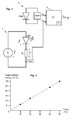
- the detection system of the invention comprises a transmitter 1 comprising a light emitting diode (LED) capable of emitting a light signal and a power source A to which the LED is connected.
- the power source A consists of a voltage source supplying a constant voltage V power supply in order to apply a constant voltage V LED to the light emitting diode LED.
- the detection system of the invention also comprises a receiver 2 remote from the transmitter 1 and having for example a photodiode (PHD) for sensing the light signals emitted by the transmitter 1 and an AMP current amplifier for transforming the electric current generated by the photodiode PHD into a first input signal S in1 operable downstream by processing means 3.
- PHD photodiode
- AMP current amplifier for transforming the electric current generated by the photodiode PHD into a first input signal S in1 operable downstream by processing means 3.
- the gas to be detected is typically placed between the transmitter 1 and the receiver 2.
- the detection system also has means for measuring the current I LED through the light emitting diode LED.
- the variation of the measured current I DEL is representative of the variation of the temperature influencing the optical power of the light-emitting diode DEL.
- the measuring means comprise, for example, a measurement resistor R m connected in series with the LED, whose voltage V R is monitored by the processing means 3 in order to deduce therefrom the current I LED passing through the LED light-emitting diode .
- the current I DEL is represented by a second input signal S in2 applied to the processing means 3.
- the first input signal S in1 and the second input signal S in2 are for example converted into digital signals by analog-digital converters implemented in the processing means 3.
- the processing means 3 comprise a microcontroller ⁇ C intended to process the two digital signals obtained to determine an output signal S out representative of the state of the detection.
- the processing consists in determining an output voltage, corresponding to the concentration of the gas to be measured, from the first input signal S in1 , the second input signal S in2 and temperature calibration parameters (T °) initially. stored in the microcontroller ⁇ C.
- These calibration parameters T ° are for example stored in a memory of the microcontroller ⁇ C and are applied to the second input signal S in2 to take into account the influence of the temperature in the determination of the output signal S out .
- the optical power of the LED constant current decreases and thus the signal-to-noise ratio SNR decreases.
- the LED when the LED is powered by a constant voltage, its current increases as the temperature increases. As a result, the loss of optical power is limited as well as the degradation of the signal-to-noise ratio SNR.
Landscapes
- Physics & Mathematics (AREA)
- General Physics & Mathematics (AREA)
- Investigating Or Analysing Materials By Optical Means (AREA)
- Photometry And Measurement Of Optical Pulse Characteristics (AREA)
- Control Of Indicators Other Than Cathode Ray Tubes (AREA)
- Selective Calling Equipment (AREA)
Abstract
- un émetteur (1) comprenant une diode électroluminescente (DEL) apte à émettre un signal lumineux et une source d'alimentation (A) agencée pour appliquer une tension constante (VDEL) à la diode électroluminescente (DEL),
- un récepteur (2) destiné à capter le signal lumineux émis par la diode électroluminescente et agencé pour générer un premier signal d'entrée (Sin1) représentatif du signal lumineux détecté,
- des moyens de mesure du courant (IDEL) traversant la diode électroluminescente (DEL) et destinés à générer un second signal d'entrée (Sin2) représentatif du courant (IDEL) mesuré,
- des moyens de traitement (3) connectés au récepteur (2) pour fournir un signal de sortie (Sout) en fonction du premier signal d'entrée (Sin1) et du second signal d'entrée (Sin2).
Description
- La présente invention se rapporte à un système de détection comportant un émetteur apte à émettre un signal lumineux, un récepteur du signal lumineux et des moyens de traitement. L'invention sera notamment parfaitement adaptée pour la détermination de la concentration d'un gaz de type dioxyde de carbone.
- Lorsqu'un système de détection emploie une diode électroluminescente comme émetteur, il est connu qu'il doit comporter des moyens permettant de limiter ou de compenser l'effet de la température sur le signal lumineux émis par la diode électroluminescente. En règle générale, ces moyens permettent de faire varier le niveau de courant injecté dans la diode électroluminescente afin de maintenir sa puissance optique à une valeur à peu près constante quelle que soit la température de la diode électroluminescente. En nécessitant une action permanente sur le courant injecté dans la diode électroluminescente, ces solutions ne vont pas dans le sens d'une faible consommation d'énergie.
- Le but de l'invention est de proposer un système de détection permettant de compenser une partie de l'effet lié à la température sur la détection effectuée tout en présentant une faible consommation d'énergie et en ne dégradant pas le rapport signal-bruit.
- Ce but est atteint par un système de détection comportant :
- un émetteur comprenant une diode électroluminescente apte à émettre un signal lumineux et une source d'alimentation agencée pour alimenter la diode électroluminescente,
- un récepteur destiné à capter le signal lumineux émis par la diode électroluminescente et agencé pour générer un premier signal d'entrée représentatif du signal lumineux détecté,
- des moyens de traitement connectés au récepteur pour fournir un signal de sortie,
- la source d'alimentation est une source de tension agencée pour appliquer une tension constante à la diode électroluminescente,
- le système comporte des moyens de mesure du courant traversant la diode électroluminescente et destinés à générer un second signal d'entrée représentatif du courant mesuré,
- les moyens de traitement comportent des moyens de détermination du signal de sortie en fonction du premier signal d'entrée et du second signal d'entrée.
- Selon une particularité, les moyens de traitement comportent un microcontrôleur mémorisant des paramètres de calibration en température employés pour déterminer le signal de sortie à partir du premier signal d'entrée et du second signal d'entrée.
- Selon une autre particularité, les moyens de mesure comportent une résistance de mesure connectée en série avec la diode électroluminescente.
- Selon une autre particularité, le récepteur comporte une photodiode et un amplificateur de courant configurés pour générer le premier signal d'entrée.
- D'autres caractéristiques et avantages vont apparaître dans la description détaillée qui suit faite en regard des dessins annexés dans lesquels :
- la
figure 1 représente le schéma de principe du système de détection de l'invention, - la
figure 2 représente la courbe d'augmentation du courant traversant la diode électroluminescente (en %) en fonction de la température (Temp) mesurée (en °C). - L'invention concerne un système de détection destiné notamment à la détermination de la concentration d'un gaz, tel que par exemple le dioxyde de carbone. Le système de détection de l'invention présente l'avantage de consommer très peu d'énergie lors de chaque mesure et de ne pas dégrader le rapport signal-bruit.
- En référence à la
figure 1 , le système de détection de l'invention comporte un émetteur 1 comprenant une diode électroluminescente (DEL) apte à émettre un signal lumineux et une source d'alimentation A à laquelle est connectée la diode électroluminescente DEL. La source d'alimentation A est constituée d'une source de tension délivrant une tension Valim constante afin de pouvoir appliquer une tension VDEL constante à la diode électroluminescente DEL. Avec une tension VDEL constante aux bornes de la diode électroluminescente DEL, le courant IDEL qui traverse la diode évolue sensiblement avec la température car la tension directe de polarisation de la diode électroluminescente DEL varie inversement avec la température. En conséquence, à tension constante, le courant qui traverse la diode électroluminescente DEL augmente de manière quasi linéaire lorsque la température augmente. La courbe représentée enfigure 2 permet d'illustrer ce phénomène. - Le système de détection de l'invention comporte également un récepteur 2 éloigné par rapport à l'émetteur 1 et comportant par exemple une photodiode (PHD) destinée à capter les signaux lumineux émis par l'émetteur 1 et un amplificateur de courant AMP permettant de transformer le courant électrique généré grâce à la photodiode PHD en un premier signal d'entrée Sin1 exploitable en aval par des moyens de traitement 3. Le gaz à détecter est typiquement placé entre l'émetteur 1 et le récepteur 2.
- Comme la diode électroluminescente DEL est alimentée par une source de tension constante, le système de détection comporte également des moyens de mesure du courant IDEL traversant la diode électroluminescente DEL. La variation du courant IDEL mesuré est représentative de la variation de la température influençant la puissance optique de la diode électroluminescente DEL. Les moyens de mesure comportent par exemple une résistance de mesure Rm connectée en série avec la diode électroluminescente DEL, dont la tension VR est surveillée par les moyens de traitement 3 en vue d'en déduire le courant IDEL traversant la diode électroluminescente DEL. Sur la
figure 1 , le courant IDEL est représenté par un second signal d'entrée Sin2 appliqué aux moyens de traitement 3. - Le premier signal d'entrée Sin1 et le second signal d'entrée Sin2 sont par exemple transformés en signaux numériques par des convertisseurs analogiques-numériques implémentés dans les moyens de traitement 3. Les moyens de traitement 3 comportent un microcontrôleur µC destiné à traiter les deux signaux numériques obtenus pour déterminer un signal de sortie Sout représentatif de l'état de la détection. Le traitement consiste à déterminer une tension de sortie, correspondant à la concentration du gaz à mesurer, à partir du premier signal d'entrée Sin1, du second signal d'entrée Sin2 et de paramètres de calibration en température (T°) initialement mémorisés dans le microcontrôleur µC. Ces paramètres de calibration T° sont par exemple stockés dans une mémoire du microcontrôleur µC et sont appliqués au second signal d'entrée Sin2 pour tenir compte de l'influence de la température dans la détermination du signal de sortie Sout.
- Par ailleurs, comme la diode électroluminescente DEL est alimentée en tension, lorsque la température augmente, la puissance optique de la diode DEL à courant constant diminue et donc le rapport signal-bruit SNR diminue. Or, lorsque la diode DEL est alimentée par une tension constante, son courant augmente lorsque la température augmente. En conséquence, la perte de puissance optique est limitée ainsi que la dégradation du rapport signal-bruit SNR.
Claims (4)
- Système de détection comportant :- un émetteur (1) comprenant une diode électroluminescente (DEL) apte à émettre un signal lumineux et une source d'alimentation (A) agencée pour alimenter la diode électroluminescente (DEL),- un récepteur (2) destiné à capter le signal lumineux émis par la diode électroluminescente et agencé pour générer un premier signal d'entrée (Sin1) représentatif du signal lumineux détecté,- des moyens de traitement (3) connectés au récepteur (2) pour fournir un signal de sortie (Sout),le système étant caractérisé en ce que :- la source d'alimentation (A) est une source de tension agencée pour appliquer une tension constante (VDEL) à la diode électroluminescente (DEL),- le système comporte des moyens de mesure du courant (IDEL) traversant la diode électroluminescente (DEL) et destinés à générer un second signal d'entrée (Sin2) représentatif du courant (IDEL) mesuré,- les moyens de traitement (3) comportent des moyens de détermination du signal de sortie (Sout) en fonction du premier signal d'entrée (Sin1) et du second signal d'entrée (Sin2).
- Système de détection selon la revendication 1, caractérisé en ce que les moyens de traitement (3) comportent un microcontrôleur (µC) mémorisant des paramètres (T°) de calibration en température employés pour déterminer le signal de sortie (Sout) à partir du premier signal d'entrée (Sin1) et du second signal d'entrée (Sin2)·
- Système de détection selon la revendication 1, caractérisé en ce que les moyens de mesure comportent une résistance de mesure (Rm) connectée en série avec la diode électroluminescente (DEL).
- Système de détection selon la revendication 1, caractérisé en ce que le récepteur (2) comporte une photodiode (PHD) et un amplificateur de courant (AMP) configurés pour générer le premier signal d'entrée (Sin1).
Applications Claiming Priority (1)
| Application Number | Priority Date | Filing Date | Title |
|---|---|---|---|
| FR1155790A FR2977315B1 (fr) | 2011-06-29 | 2011-06-29 | Systeme de detection a faible consommation d'energie |
Publications (2)
| Publication Number | Publication Date |
|---|---|
| EP2541212A1 true EP2541212A1 (fr) | 2013-01-02 |
| EP2541212B1 EP2541212B1 (fr) | 2014-10-08 |
Family
ID=46125327
Family Applications (1)
| Application Number | Title | Priority Date | Filing Date |
|---|---|---|---|
| EP20120169775 Active EP2541212B1 (fr) | 2011-06-29 | 2012-05-29 | Système de détection à faible consommation d'énergie |
Country Status (6)
| Country | Link |
|---|---|
| US (1) | US9121727B2 (fr) |
| EP (1) | EP2541212B1 (fr) |
| CN (1) | CN102854140B (fr) |
| CA (1) | CA2781034C (fr) |
| ES (1) | ES2524903T3 (fr) |
| FR (1) | FR2977315B1 (fr) |
Cited By (1)
| Publication number | Priority date | Publication date | Assignee | Title |
|---|---|---|---|---|
| CN105043426A (zh) * | 2015-08-14 | 2015-11-11 | 昂纳信息技术(深圳)有限公司 | 在线监测及调节光纤传感器性能的方法 |
Families Citing this family (2)
| Publication number | Priority date | Publication date | Assignee | Title |
|---|---|---|---|---|
| CN111247419A (zh) * | 2017-09-13 | 2020-06-05 | (株)吉普朗 | 具有增强检测能力的传感器 |
| TWI734156B (zh) * | 2019-07-26 | 2021-07-21 | 義隆電子股份有限公司 | 煙霧感測裝置 |
Citations (3)
| Publication number | Priority date | Publication date | Assignee | Title |
|---|---|---|---|---|
| US5165380A (en) * | 1990-11-27 | 1992-11-24 | Mitsubishi Denki Kabushiki Kaisha | Distributor with a built-in crank angle sensor |
| US6356774B1 (en) * | 1998-09-29 | 2002-03-12 | Mallinckrodt, Inc. | Oximeter sensor with encoded temperature characteristic |
| US6574425B1 (en) * | 1997-10-31 | 2003-06-03 | Jack L. Aronowitz | Reflectometer |
Family Cites Families (5)
| Publication number | Priority date | Publication date | Assignee | Title |
|---|---|---|---|---|
| US5085508A (en) * | 1990-01-16 | 1992-02-04 | Pittway Corporation | Beam alignment apparatus and method usable with projected beam smoke detector systems |
| JPH06288917A (ja) * | 1993-03-31 | 1994-10-18 | Nohmi Bosai Ltd | 煙式火災感知器 |
| CN2486967Y (zh) * | 2000-09-30 | 2002-04-17 | 边东福 | 一种监测硅磷酸根的水样分析装置 |
| CN1916600A (zh) * | 2005-08-15 | 2007-02-21 | 南京信息工程大学 | 一种甲醛气体含量的快速测量装置 |
| DE102012007016B3 (de) * | 2012-04-05 | 2013-10-10 | Dräger Safety AG & Co. KGaA | Optischer Gassensor |
-
2011
- 2011-06-29 FR FR1155790A patent/FR2977315B1/fr not_active Expired - Fee Related
-
2012
- 2012-05-23 US US13/478,297 patent/US9121727B2/en active Active
- 2012-05-29 ES ES12169775.9T patent/ES2524903T3/es active Active
- 2012-05-29 EP EP20120169775 patent/EP2541212B1/fr active Active
- 2012-06-18 CA CA 2781034 patent/CA2781034C/fr active Active
- 2012-06-28 CN CN201210219370.5A patent/CN102854140B/zh active Active
Patent Citations (3)
| Publication number | Priority date | Publication date | Assignee | Title |
|---|---|---|---|---|
| US5165380A (en) * | 1990-11-27 | 1992-11-24 | Mitsubishi Denki Kabushiki Kaisha | Distributor with a built-in crank angle sensor |
| US6574425B1 (en) * | 1997-10-31 | 2003-06-03 | Jack L. Aronowitz | Reflectometer |
| US6356774B1 (en) * | 1998-09-29 | 2002-03-12 | Mallinckrodt, Inc. | Oximeter sensor with encoded temperature characteristic |
Cited By (1)
| Publication number | Priority date | Publication date | Assignee | Title |
|---|---|---|---|---|
| CN105043426A (zh) * | 2015-08-14 | 2015-11-11 | 昂纳信息技术(深圳)有限公司 | 在线监测及调节光纤传感器性能的方法 |
Also Published As
| Publication number | Publication date |
|---|---|
| CA2781034A1 (fr) | 2012-12-29 |
| CN102854140B (zh) | 2015-03-25 |
| FR2977315B1 (fr) | 2013-06-28 |
| CN102854140A (zh) | 2013-01-02 |
| CA2781034C (fr) | 2015-01-13 |
| US20130001397A1 (en) | 2013-01-03 |
| US9121727B2 (en) | 2015-09-01 |
| EP2541212B1 (fr) | 2014-10-08 |
| FR2977315A1 (fr) | 2013-01-04 |
| ES2524903T3 (es) | 2014-12-15 |
Similar Documents
| Publication | Publication Date | Title |
|---|---|---|
| EP0583186B1 (fr) | Dispositif de contrÔle de la puissance de sortie des diodes laser | |
| FR3023917B1 (fr) | Dispositif capteur de gaz destine a la mesure d'une concentration de gaz cible | |
| EP2541212B1 (fr) | Système de détection à faible consommation d'énergie | |
| CN106253853B (zh) | 信号处理装置以及噪声强度决定方法 | |
| JP2016128795A (ja) | 粒子測定装置、空気清浄機、及び、粒子測定方法 | |
| KR102233064B1 (ko) | 레이저 기반 입자 검출기의 동작 조건을 검출하는 방법 | |
| JP6410679B2 (ja) | ガスセンサ | |
| JP6233711B2 (ja) | 粒子測定装置 | |
| JP2015210189A (ja) | 粒子測定装置 | |
| EP3513628B1 (fr) | Circuit électronique et capteur de temps de vol comprenant un tel circuit électronique | |
| EP3985631B1 (fr) | Détecteur optique de fumée | |
| US9816920B2 (en) | Method for producing an integrated micromechanical fluid sensor component, integrated micromechanical fluid sensor component and method for detecting a fluid by means of an integrated micromechanical fluid sensor component | |
| JP2017142142A (ja) | 粒子検出センサ、携帯型気体モニタ、及び、粒子検出方法 | |
| JP5940388B2 (ja) | 雨滴検出装置 | |
| JP2016095171A (ja) | 信号出力装置、粒子測定装置および信号出力装置の記憶方法 | |
| FR3131456A1 (fr) | Batterie electrique pour aeronef | |
| EP2941631A1 (fr) | Capteur de concentration de co2 | |
| FR2966241A1 (fr) | Capteur apte a determiner un dysfonctionnement interne et procede de diagnostic pour un tel capteur | |
| EP1927861A1 (fr) | Procédé et dispositif de détermination de l' état rotatif d'une roue d'un véhicule équipée d'un capteur actif de mouvement adapté pour délivrer un signal de sortie oscillatoire lors d'une rotation de la dite roue | |
| EP2568600B1 (fr) | Dispositif de détection avec un montage transimpédance | |
| JP2013142626A (ja) | 不純物粒子測定装置 | |
| JP2016109629A (ja) | 粒子測定装置、空気清浄機、及び、粒子測定方法 | |
| FR3033975B1 (fr) | Procede et systeme de surveillance de l'etat d'une diode electroluminescente d'un dispositif d'eclairage en cours de vie de la diode | |
| EP3201576B1 (fr) | Dispositif de détection de flux d'air | |
| JP2015210184A (ja) | 粒子測定装置 |
Legal Events
| Date | Code | Title | Description |
|---|---|---|---|
| PUAI | Public reference made under article 153(3) epc to a published international application that has entered the european phase |
Free format text: ORIGINAL CODE: 0009012 |
|
| AK | Designated contracting states |
Kind code of ref document: A1 Designated state(s): AL AT BE BG CH CY CZ DE DK EE ES FI FR GB GR HR HU IE IS IT LI LT LU LV MC MK MT NL NO PL PT RO RS SE SI SK SM TR |
|
| AX | Request for extension of the european patent |
Extension state: BA ME |
|
| 17P | Request for examination filed |
Effective date: 20130116 |
|
| REG | Reference to a national code |
Ref country code: DE Ref legal event code: R079 Ref document number: 602012003304 Country of ref document: DE Free format text: PREVIOUS MAIN CLASS: G01D0003028000 Ipc: G01D0005340000 |
|
| GRAP | Despatch of communication of intention to grant a patent |
Free format text: ORIGINAL CODE: EPIDOSNIGR1 |
|
| RIC1 | Information provided on ipc code assigned before grant |
Ipc: G01D 5/34 20060101AFI20140630BHEP Ipc: G01D 3/036 20060101ALI20140630BHEP |
|
| INTG | Intention to grant announced |
Effective date: 20140714 |
|
| GRAS | Grant fee paid |
Free format text: ORIGINAL CODE: EPIDOSNIGR3 |
|
| GRAA | (expected) grant |
Free format text: ORIGINAL CODE: 0009210 |
|
| AK | Designated contracting states |
Kind code of ref document: B1 Designated state(s): AL AT BE BG CH CY CZ DE DK EE ES FI FR GB GR HR HU IE IS IT LI LT LU LV MC MK MT NL NO PL PT RO RS SE SI SK SM TR |
|
| REG | Reference to a national code |
Ref country code: GB Ref legal event code: FG4D Free format text: NOT ENGLISH |
|
| REG | Reference to a national code |
Ref country code: CH Ref legal event code: EP Ref country code: AT Ref legal event code: REF Ref document number: 690877 Country of ref document: AT Kind code of ref document: T Effective date: 20141015 |
|
| REG | Reference to a national code |
Ref country code: IE Ref legal event code: FG4D Free format text: LANGUAGE OF EP DOCUMENT: FRENCH |
|
| REG | Reference to a national code |
Ref country code: DE Ref legal event code: R096 Ref document number: 602012003304 Country of ref document: DE Effective date: 20141120 |
|
| REG | Reference to a national code |
Ref country code: ES Ref legal event code: FG2A Ref document number: 2524903 Country of ref document: ES Kind code of ref document: T3 Effective date: 20141215 |
|
| REG | Reference to a national code |
Ref country code: NL Ref legal event code: VDEP Effective date: 20141008 |
|
| REG | Reference to a national code |
Ref country code: AT Ref legal event code: MK05 Ref document number: 690877 Country of ref document: AT Kind code of ref document: T Effective date: 20141008 |
|
| REG | Reference to a national code |
Ref country code: LT Ref legal event code: MG4D |
|
| PG25 | Lapsed in a contracting state [announced via postgrant information from national office to epo] |
Ref country code: NL Free format text: LAPSE BECAUSE OF FAILURE TO SUBMIT A TRANSLATION OF THE DESCRIPTION OR TO PAY THE FEE WITHIN THE PRESCRIBED TIME-LIMIT Effective date: 20141008 |
|
| REG | Reference to a national code |
Ref country code: FR Ref legal event code: PLFP Year of fee payment: 4 |
|
| PG25 | Lapsed in a contracting state [announced via postgrant information from national office to epo] |
Ref country code: LT Free format text: LAPSE BECAUSE OF FAILURE TO SUBMIT A TRANSLATION OF THE DESCRIPTION OR TO PAY THE FEE WITHIN THE PRESCRIBED TIME-LIMIT Effective date: 20141008 Ref country code: FI Free format text: LAPSE BECAUSE OF FAILURE TO SUBMIT A TRANSLATION OF THE DESCRIPTION OR TO PAY THE FEE WITHIN THE PRESCRIBED TIME-LIMIT Effective date: 20141008 Ref country code: PT Free format text: LAPSE BECAUSE OF FAILURE TO SUBMIT A TRANSLATION OF THE DESCRIPTION OR TO PAY THE FEE WITHIN THE PRESCRIBED TIME-LIMIT Effective date: 20150209 Ref country code: NO Free format text: LAPSE BECAUSE OF FAILURE TO SUBMIT A TRANSLATION OF THE DESCRIPTION OR TO PAY THE FEE WITHIN THE PRESCRIBED TIME-LIMIT Effective date: 20150108 Ref country code: IS Free format text: LAPSE BECAUSE OF FAILURE TO SUBMIT A TRANSLATION OF THE DESCRIPTION OR TO PAY THE FEE WITHIN THE PRESCRIBED TIME-LIMIT Effective date: 20150208 |
|
| PG25 | Lapsed in a contracting state [announced via postgrant information from national office to epo] |
Ref country code: PL Free format text: LAPSE BECAUSE OF FAILURE TO SUBMIT A TRANSLATION OF THE DESCRIPTION OR TO PAY THE FEE WITHIN THE PRESCRIBED TIME-LIMIT Effective date: 20141008 Ref country code: CY Free format text: LAPSE BECAUSE OF FAILURE TO SUBMIT A TRANSLATION OF THE DESCRIPTION OR TO PAY THE FEE WITHIN THE PRESCRIBED TIME-LIMIT Effective date: 20141008 Ref country code: AT Free format text: LAPSE BECAUSE OF FAILURE TO SUBMIT A TRANSLATION OF THE DESCRIPTION OR TO PAY THE FEE WITHIN THE PRESCRIBED TIME-LIMIT Effective date: 20141008 Ref country code: HR Free format text: LAPSE BECAUSE OF FAILURE TO SUBMIT A TRANSLATION OF THE DESCRIPTION OR TO PAY THE FEE WITHIN THE PRESCRIBED TIME-LIMIT Effective date: 20141008 Ref country code: GR Free format text: LAPSE BECAUSE OF FAILURE TO SUBMIT A TRANSLATION OF THE DESCRIPTION OR TO PAY THE FEE WITHIN THE PRESCRIBED TIME-LIMIT Effective date: 20150109 Ref country code: SE Free format text: LAPSE BECAUSE OF FAILURE TO SUBMIT A TRANSLATION OF THE DESCRIPTION OR TO PAY THE FEE WITHIN THE PRESCRIBED TIME-LIMIT Effective date: 20141008 Ref country code: LV Free format text: LAPSE BECAUSE OF FAILURE TO SUBMIT A TRANSLATION OF THE DESCRIPTION OR TO PAY THE FEE WITHIN THE PRESCRIBED TIME-LIMIT Effective date: 20141008 Ref country code: RS Free format text: LAPSE BECAUSE OF FAILURE TO SUBMIT A TRANSLATION OF THE DESCRIPTION OR TO PAY THE FEE WITHIN THE PRESCRIBED TIME-LIMIT Effective date: 20141008 |
|
| REG | Reference to a national code |
Ref country code: DE Ref legal event code: R097 Ref document number: 602012003304 Country of ref document: DE |
|
| PG25 | Lapsed in a contracting state [announced via postgrant information from national office to epo] |
Ref country code: SK Free format text: LAPSE BECAUSE OF FAILURE TO SUBMIT A TRANSLATION OF THE DESCRIPTION OR TO PAY THE FEE WITHIN THE PRESCRIBED TIME-LIMIT Effective date: 20141008 Ref country code: EE Free format text: LAPSE BECAUSE OF FAILURE TO SUBMIT A TRANSLATION OF THE DESCRIPTION OR TO PAY THE FEE WITHIN THE PRESCRIBED TIME-LIMIT Effective date: 20141008 Ref country code: DK Free format text: LAPSE BECAUSE OF FAILURE TO SUBMIT A TRANSLATION OF THE DESCRIPTION OR TO PAY THE FEE WITHIN THE PRESCRIBED TIME-LIMIT Effective date: 20141008 Ref country code: CZ Free format text: LAPSE BECAUSE OF FAILURE TO SUBMIT A TRANSLATION OF THE DESCRIPTION OR TO PAY THE FEE WITHIN THE PRESCRIBED TIME-LIMIT Effective date: 20141008 Ref country code: RO Free format text: LAPSE BECAUSE OF FAILURE TO SUBMIT A TRANSLATION OF THE DESCRIPTION OR TO PAY THE FEE WITHIN THE PRESCRIBED TIME-LIMIT Effective date: 20141008 |
|
| PLBE | No opposition filed within time limit |
Free format text: ORIGINAL CODE: 0009261 |
|
| STAA | Information on the status of an ep patent application or granted ep patent |
Free format text: STATUS: NO OPPOSITION FILED WITHIN TIME LIMIT |
|
| 26N | No opposition filed |
Effective date: 20150709 |
|
| REG | Reference to a national code |
Ref country code: CH Ref legal event code: PL |
|
| PG25 | Lapsed in a contracting state [announced via postgrant information from national office to epo] |
Ref country code: LI Free format text: LAPSE BECAUSE OF NON-PAYMENT OF DUE FEES Effective date: 20150531 Ref country code: MC Free format text: LAPSE BECAUSE OF FAILURE TO SUBMIT A TRANSLATION OF THE DESCRIPTION OR TO PAY THE FEE WITHIN THE PRESCRIBED TIME-LIMIT Effective date: 20141008 Ref country code: CH Free format text: LAPSE BECAUSE OF NON-PAYMENT OF DUE FEES Effective date: 20150531 Ref country code: LU Free format text: LAPSE BECAUSE OF FAILURE TO SUBMIT A TRANSLATION OF THE DESCRIPTION OR TO PAY THE FEE WITHIN THE PRESCRIBED TIME-LIMIT Effective date: 20150529 |
|
| REG | Reference to a national code |
Ref country code: IE Ref legal event code: MM4A |
|
| PG25 | Lapsed in a contracting state [announced via postgrant information from national office to epo] |
Ref country code: SI Free format text: LAPSE BECAUSE OF FAILURE TO SUBMIT A TRANSLATION OF THE DESCRIPTION OR TO PAY THE FEE WITHIN THE PRESCRIBED TIME-LIMIT Effective date: 20141008 |
|
| REG | Reference to a national code |
Ref country code: FR Ref legal event code: PLFP Year of fee payment: 5 |
|
| PG25 | Lapsed in a contracting state [announced via postgrant information from national office to epo] |
Ref country code: IE Free format text: LAPSE BECAUSE OF NON-PAYMENT OF DUE FEES Effective date: 20150529 |
|
| PG25 | Lapsed in a contracting state [announced via postgrant information from national office to epo] |
Ref country code: MT Free format text: LAPSE BECAUSE OF FAILURE TO SUBMIT A TRANSLATION OF THE DESCRIPTION OR TO PAY THE FEE WITHIN THE PRESCRIBED TIME-LIMIT Effective date: 20141008 |
|
| REG | Reference to a national code |
Ref country code: FR Ref legal event code: PLFP Year of fee payment: 6 |
|
| PG25 | Lapsed in a contracting state [announced via postgrant information from national office to epo] |
Ref country code: SM Free format text: LAPSE BECAUSE OF FAILURE TO SUBMIT A TRANSLATION OF THE DESCRIPTION OR TO PAY THE FEE WITHIN THE PRESCRIBED TIME-LIMIT Effective date: 20141008 Ref country code: HU Free format text: LAPSE BECAUSE OF FAILURE TO SUBMIT A TRANSLATION OF THE DESCRIPTION OR TO PAY THE FEE WITHIN THE PRESCRIBED TIME-LIMIT; INVALID AB INITIO Effective date: 20120529 Ref country code: BG Free format text: LAPSE BECAUSE OF FAILURE TO SUBMIT A TRANSLATION OF THE DESCRIPTION OR TO PAY THE FEE WITHIN THE PRESCRIBED TIME-LIMIT Effective date: 20141008 |
|
| PG25 | Lapsed in a contracting state [announced via postgrant information from national office to epo] |
Ref country code: BE Free format text: LAPSE BECAUSE OF NON-PAYMENT OF DUE FEES Effective date: 20150531 |
|
| PG25 | Lapsed in a contracting state [announced via postgrant information from national office to epo] |
Ref country code: TR Free format text: LAPSE BECAUSE OF FAILURE TO SUBMIT A TRANSLATION OF THE DESCRIPTION OR TO PAY THE FEE WITHIN THE PRESCRIBED TIME-LIMIT Effective date: 20141008 |
|
| REG | Reference to a national code |
Ref country code: FR Ref legal event code: PLFP Year of fee payment: 7 |
|
| PG25 | Lapsed in a contracting state [announced via postgrant information from national office to epo] |
Ref country code: MK Free format text: LAPSE BECAUSE OF FAILURE TO SUBMIT A TRANSLATION OF THE DESCRIPTION OR TO PAY THE FEE WITHIN THE PRESCRIBED TIME-LIMIT Effective date: 20141008 |
|
| PG25 | Lapsed in a contracting state [announced via postgrant information from national office to epo] |
Ref country code: AL Free format text: LAPSE BECAUSE OF FAILURE TO SUBMIT A TRANSLATION OF THE DESCRIPTION OR TO PAY THE FEE WITHIN THE PRESCRIBED TIME-LIMIT Effective date: 20141008 |
|
| PGFP | Annual fee paid to national office [announced via postgrant information from national office to epo] |
Ref country code: IT Payment date: 20200512 Year of fee payment: 9 |
|
| PG25 | Lapsed in a contracting state [announced via postgrant information from national office to epo] |
Ref country code: IT Free format text: LAPSE BECAUSE OF NON-PAYMENT OF DUE FEES Effective date: 20200529 |
|
| PGFP | Annual fee paid to national office [announced via postgrant information from national office to epo] |
Ref country code: DE Payment date: 20250528 Year of fee payment: 14 |
|
| PGFP | Annual fee paid to national office [announced via postgrant information from national office to epo] |
Ref country code: GB Payment date: 20250526 Year of fee payment: 14 Ref country code: ES Payment date: 20250611 Year of fee payment: 14 |
|
| PGFP | Annual fee paid to national office [announced via postgrant information from national office to epo] |
Ref country code: FR Payment date: 20250526 Year of fee payment: 14 |