EP2541180A1 - Heat exchanger - Google Patents
Heat exchanger Download PDFInfo
- Publication number
- EP2541180A1 EP2541180A1 EP12172200A EP12172200A EP2541180A1 EP 2541180 A1 EP2541180 A1 EP 2541180A1 EP 12172200 A EP12172200 A EP 12172200A EP 12172200 A EP12172200 A EP 12172200A EP 2541180 A1 EP2541180 A1 EP 2541180A1
- Authority
- EP
- European Patent Office
- Prior art keywords
- fuel
- heat exchanger
- swirl
- matrix
- ice
- Prior art date
- Legal status (The legal status is an assumption and is not a legal conclusion. Google has not performed a legal analysis and makes no representation as to the accuracy of the status listed.)
- Granted
Links
- 239000000446 fuel Substances 0.000 claims abstract description 174
- 239000011159 matrix material Substances 0.000 claims abstract description 46
- 230000001939 inductive effect Effects 0.000 claims abstract description 18
- 239000012141 concentrate Substances 0.000 claims abstract description 7
- 238000010792 warming Methods 0.000 claims abstract description 3
- 238000000034 method Methods 0.000 claims description 13
- 238000010438 heat treatment Methods 0.000 claims description 3
- 239000000155 melt Substances 0.000 claims description 3
- 238000013019 agitation Methods 0.000 claims description 2
- 239000002245 particle Substances 0.000 description 15
- 239000003921 oil Substances 0.000 description 8
- 239000000295 fuel oil Substances 0.000 description 7
- 238000009825 accumulation Methods 0.000 description 3
- 238000002485 combustion reaction Methods 0.000 description 3
- 230000007257 malfunction Effects 0.000 description 3
- 230000001141 propulsive effect Effects 0.000 description 3
- XLYOFNOQVPJJNP-UHFFFAOYSA-N water Substances O XLYOFNOQVPJJNP-UHFFFAOYSA-N 0.000 description 3
- 230000000903 blocking effect Effects 0.000 description 1
- 230000006835 compression Effects 0.000 description 1
- 238000007906 compression Methods 0.000 description 1
- 238000001816 cooling Methods 0.000 description 1
- 230000000694 effects Effects 0.000 description 1
- 239000002828 fuel tank Substances 0.000 description 1
- 239000007788 liquid Substances 0.000 description 1
- 239000000203 mixture Substances 0.000 description 1
- 238000012986 modification Methods 0.000 description 1
- 230000004048 modification Effects 0.000 description 1
- 239000010705 motor oil Substances 0.000 description 1
- 230000000717 retained effect Effects 0.000 description 1
- 239000000725 suspension Substances 0.000 description 1
- 230000001052 transient effect Effects 0.000 description 1
Images


Classifications
-
- F—MECHANICAL ENGINEERING; LIGHTING; HEATING; WEAPONS; BLASTING
- F28—HEAT EXCHANGE IN GENERAL
- F28F—DETAILS OF HEAT-EXCHANGE AND HEAT-TRANSFER APPARATUS, OF GENERAL APPLICATION
- F28F9/00—Casings; Header boxes; Auxiliary supports for elements; Auxiliary members within casings
- F28F9/02—Header boxes; End plates
- F28F9/026—Header boxes; End plates with static flow control means, e.g. with means for uniformly distributing heat exchange media into conduits
-
- F—MECHANICAL ENGINEERING; LIGHTING; HEATING; WEAPONS; BLASTING
- F02—COMBUSTION ENGINES; HOT-GAS OR COMBUSTION-PRODUCT ENGINE PLANTS
- F02C—GAS-TURBINE PLANTS; AIR INTAKES FOR JET-PROPULSION PLANTS; CONTROLLING FUEL SUPPLY IN AIR-BREATHING JET-PROPULSION PLANTS
- F02C7/00—Features, components parts, details or accessories, not provided for in, or of interest apart form groups F02C1/00 - F02C6/00; Air intakes for jet-propulsion plants
- F02C7/22—Fuel supply systems
- F02C7/224—Heating fuel before feeding to the burner
-
- F—MECHANICAL ENGINEERING; LIGHTING; HEATING; WEAPONS; BLASTING
- F28—HEAT EXCHANGE IN GENERAL
- F28D—HEAT-EXCHANGE APPARATUS, NOT PROVIDED FOR IN ANOTHER SUBCLASS, IN WHICH THE HEAT-EXCHANGE MEDIA DO NOT COME INTO DIRECT CONTACT
- F28D7/00—Heat-exchange apparatus having stationary tubular conduit assemblies for both heat-exchange media, the media being in contact with different sides of a conduit wall
- F28D7/16—Heat-exchange apparatus having stationary tubular conduit assemblies for both heat-exchange media, the media being in contact with different sides of a conduit wall the conduits being arranged in parallel spaced relation
- F28D7/163—Heat-exchange apparatus having stationary tubular conduit assemblies for both heat-exchange media, the media being in contact with different sides of a conduit wall the conduits being arranged in parallel spaced relation with conduit assemblies having a particular shape, e.g. square or annular; with assemblies of conduits having different geometrical features; with multiple groups of conduits connected in series or parallel and arranged inside common casing
- F28D7/1669—Heat-exchange apparatus having stationary tubular conduit assemblies for both heat-exchange media, the media being in contact with different sides of a conduit wall the conduits being arranged in parallel spaced relation with conduit assemblies having a particular shape, e.g. square or annular; with assemblies of conduits having different geometrical features; with multiple groups of conduits connected in series or parallel and arranged inside common casing the conduit assemblies having an annular shape; the conduits being assembled around a central distribution tube
-
- F—MECHANICAL ENGINEERING; LIGHTING; HEATING; WEAPONS; BLASTING
- F28—HEAT EXCHANGE IN GENERAL
- F28F—DETAILS OF HEAT-EXCHANGE AND HEAT-TRANSFER APPARATUS, OF GENERAL APPLICATION
- F28F13/00—Arrangements for modifying heat-transfer, e.g. increasing, decreasing
- F28F13/06—Arrangements for modifying heat-transfer, e.g. increasing, decreasing by affecting the pattern of flow of the heat-exchange media
- F28F13/12—Arrangements for modifying heat-transfer, e.g. increasing, decreasing by affecting the pattern of flow of the heat-exchange media by creating turbulence, e.g. by stirring, by increasing the force of circulation
-
- F—MECHANICAL ENGINEERING; LIGHTING; HEATING; WEAPONS; BLASTING
- F28—HEAT EXCHANGE IN GENERAL
- F28F—DETAILS OF HEAT-EXCHANGE AND HEAT-TRANSFER APPARATUS, OF GENERAL APPLICATION
- F28F13/00—Arrangements for modifying heat-transfer, e.g. increasing, decreasing
- F28F13/06—Arrangements for modifying heat-transfer, e.g. increasing, decreasing by affecting the pattern of flow of the heat-exchange media
- F28F13/12—Arrangements for modifying heat-transfer, e.g. increasing, decreasing by affecting the pattern of flow of the heat-exchange media by creating turbulence, e.g. by stirring, by increasing the force of circulation
- F28F13/125—Arrangements for modifying heat-transfer, e.g. increasing, decreasing by affecting the pattern of flow of the heat-exchange media by creating turbulence, e.g. by stirring, by increasing the force of circulation by stirring
-
- F—MECHANICAL ENGINEERING; LIGHTING; HEATING; WEAPONS; BLASTING
- F28—HEAT EXCHANGE IN GENERAL
- F28F—DETAILS OF HEAT-EXCHANGE AND HEAT-TRANSFER APPARATUS, OF GENERAL APPLICATION
- F28F27/00—Control arrangements or safety devices specially adapted for heat-exchange or heat-transfer apparatus
- F28F27/02—Control arrangements or safety devices specially adapted for heat-exchange or heat-transfer apparatus for controlling the distribution of heat-exchange media between different channels
-
- F—MECHANICAL ENGINEERING; LIGHTING; HEATING; WEAPONS; BLASTING
- F28—HEAT EXCHANGE IN GENERAL
- F28F—DETAILS OF HEAT-EXCHANGE AND HEAT-TRANSFER APPARATUS, OF GENERAL APPLICATION
- F28F9/00—Casings; Header boxes; Auxiliary supports for elements; Auxiliary members within casings
- F28F9/02—Header boxes; End plates
- F28F9/026—Header boxes; End plates with static flow control means, e.g. with means for uniformly distributing heat exchange media into conduits
- F28F9/0265—Header boxes; End plates with static flow control means, e.g. with means for uniformly distributing heat exchange media into conduits by using guiding means or impingement means inside the header box
- F28F9/0268—Header boxes; End plates with static flow control means, e.g. with means for uniformly distributing heat exchange media into conduits by using guiding means or impingement means inside the header box in the form of multiple deflectors for channeling the heat exchange medium
Definitions
- the present invention relates to a heat exchanger and a method of operating a heat exchanger.
- the invention is particularly, but not exclusively, concerned with a heat exchanger which pre-heats fuel being supplied to a gas turbine and in which the effects of fuel borne ice can be reduced.
- a ducted fan gas turbine engine generally indicated at 10 has a principal and rotational axis X-X.
- the engine comprises, in axial flow series, an air intake 11, a propulsive fan 12, an intermediate pressure compressor 13, a high-pressure compressor 14, combustion equipment 15, a high-pressure turbine 16, and intermediate pressure turbine 17, a low-pressure turbine 18 and a core engine exhaust nozzle 19.
- a nacelle 21 generally surrounds the engine 10 and defines the intake 11, a bypass duct 22 and a bypass exhaust nozzle1 23.
- the gas turbine engine 10 works in a conventional manner so that air entering the intake 11 is accelerated by the fan 12 to produce two air flows: a first air flow A into the intermediate pressure compressor 14 and a second air flow B which passes through the bypass duct 22 to provide propulsive thrust.
- the intermediate pressure compressor 13 compresses the air flow A directed into it before delivering that air to the high pressure compressor 14 where further compression takes place.
- the compressed air exhausted from the high-pressure compressor 14 is directed into the combustion equipment 15 where it is mixed with fuel and the mixture combusted.
- the resultant hot combustion products then expand through, and thereby drive the high, intermediate and low-pressure turbines 16, 17, 18 before being exhausted through the nozzle 19 to provide additional propulsive thrust.
- the high, intermediate and low-pressure turbines respectively drive the high and intermediate pressure compressors 14, 13 and the fan 12 by suitable interconnecting shafts.
- the fuel flow supplied to gas turbine engines can contain water. During operation under low ambient temperature operating conditions if the fuel is at a temperature below 0° C, the water will freeze. In these circumstances the fuel will normally enter the engine containing dispersed ice particles in suspension in the fuel. These ice particles present a problem for the fuel system in that they can block small passages and cause fine clearance valves to malfunction.
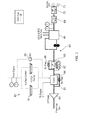
- FIG. 2 A typical arrangement of such a fuel-oil heat exchanger is shown in Figure 2 .
- a fuel-oil heat exchanger 30 is arranged in the fuel flow path 60 from the fuel tank (not shown) to the burners 71 of the engine. Fuel passing through the fuel-oil heat exchanger 30 is heated by an oil circuit 80 which supplies hot oil from the engine through surface coolers 81 (or via oil bypass valve 82) to the heat exchanger 30. The heated fuel subsequently passes to the low pressure filter 65 to the hydro-mechanical unit 68 which performs fuel management functions in response to pilot demand for thrust and controls turbine case cooling (TCC) and the variable stator vane actuator (VSVA). The fuel then passes through flow meter 69 and high pressure filter 70 to the burners 71.
- TCC turbine case cooling
- VSVA variable stator vane actuator
- Prior art systems address this problem by providing a bypass valve 64 which provides an alternative route for fuel to reach the engine. If the heat exchanger 30 becomes blocked with ice a pressure operated bypass valve 64 opens to allow fuel to bypass the blocked heat exchanger and still be supplied to the downstream components 65-71 described above to enable the engine to continue to operate.
- the heat exchanger fuel side inlet is designed to have sufficient volume to accommodate expected transient quantities of ice, such that when the bypass opens only fuel with the normal (steady state) level of ice concentration will pass to the downstream fuel system components.
- the low pressure filter 65 may also need to be provided with a bypass valve 66 which operates if the pressure difference across the filter as measured by the pressure sensor 67 becomes too great due to ice accumulation.
- Another problem with this arrangement is that it relies on the transiently high level of ice in the fuel to occur over a short period of time, such that all of this ice is captured in the heat exchanger inlet before the bypass is opened, otherwise fuel could be delivered to the downstream components which still contains high concentrations of ice which would cause malfunction of those components.
- a first aspect of the present invention provides a heat exchanger in which the fuel entering the heat exchanger is caused to swirl in order to separate any entrained ice. This allows different parts of the heat exchanger to be adapted to deal with the ice whilst fuel with low or zero concentrations of ice continues to pass through the heat exchanger to downstream components.
- a first aspect of the present invention provides a heat exchanger for warming fuel prior to introduction of the fuel to an engine, the heat exchanger including: a fuel inlet and a fuel outlet; a heat exchange matrix having heat transfer components past which the fuel flows between said inlet and said outlet and which are arranged to be heated; and swirl inducing means arranged between said inlet and said matrix arranged to cause fuel from said inlet to swirl prior to entering said matrix.
- ice particles entrained in the fuel can be concentrated in a particular area of the heat exchanger thereby leaving other areas of the heat exchanger free from ice particles and allowing fuel which is free of, or which contains a reduced amount of ice, to pass through the heat exchanger and on to downstream fuel system components and the engine.
- the swirl inducing means is arranged to cause the fuel to swirl about an axis which is substantially parallel to the main direction of fuel flow through said matrix. This action causes ice particles entrained in the fuel to concentrate in outer regions of the heat exchanger and therefore leave a central region of the heat exchanger free from deposited ice particles to permit fuel flow.
- the swirl inducing means forms part of said fuel inlet and is arranged to cause the fuel to enter the heat exchanger substantially perpendicular to the main direction of fuel flow through said matrix and at a position offset from a central axis of the heat exchanger.
- the heat exchanger is substantially cylindrical and the swirl inducing means is arranged to cause the fuel to enter the heat exchanger substantially tangentially.
- a cylindrical configuration of the heat exchanger, at least in the region of the fuel entry, is likely to result in a swirling flow of the fuel which is assisted by the curve of the interior of the heat exchanger and that the swirling flow of the fuel is maintained up to the point at which the fuel enters the heat exchange matrix.
- the swirl inducing means includes a guide vane arranged to cause the fuel to swirl prior to the fuel entering said matrix.
- the swirl inducing means may include a plurality of such guide vanes.
- Guide vanes may be used to cause fuel which enters a heat exchanger in standard fashion to swirl.
- a plurality of guide vanes may be used to improve the uniformity of the swirled fuel flow.
- the swirl inducing means includes a driven element which is arranged to cause the fuel to swirl prior to the fuel entering said matrix.
- the driven element may be an impeller which is arranged to rotate about an axis which is substantially parallel to the main direction of fuel flow through said matrix.
- a driven element as part of the swirl inducing means can ensure that a sufficient velocity of swirling fuel flow is achieved in the heat exchanger, and in particular that the velocity of the swirling fuel flow is not affected by the rate of fuel flow entering the heat exchanger.
- a plurality of different swirl inducing means including some, all or none of the specific swirl inducing means set out above may be combined in a heat exchanger.
- a second aspect of the present invention provides a gas turbine engine having a heat exchanger according to the above first aspect, including some, all or none of the optional or preferred features of that aspect.
- a gas turbine engine provides for improved resistance to icing in the fuel input to the engine and therefore improved safety in operation and a wider operating range for the engine.
- the provision of a heat exchanger according to the above first aspect may mean that the ice tolerance of the fuel supply system of the engine downstream of the heat exchanger can be reduced due to the improved ice treatment carried out in the heat exchanger.
- a further aspect of the present invention provides a method of treating fuel, the method including the step of causing fuel to swirl in the early part of a heat exchanger so that entrained ice is concentrated in a specific portion of the fuel flow.
- a third aspect of the present invention provides a method of treating fuel having entrained ice in a heat exchanger, the method including the steps of: causing said fuel to swirl so that the entrained ice concentrates in an outer portion of the fuel flow; passing the swirled fuel through a heat exchanger matrix.
- the heat exchanger can be constructed so as to deal with the concentration of ice in that portion of flow whilst allowing the portion of the fuel flow which has a lower concentration of entrained ice (or no entrained ice) to pass through the heat exchanger and on to the downstream components in the fuel supply system.
- the step of causing the fuel to swirl may cause at least some of the entrained ice to deposit on a surface of the heat exchanger prior to the fuel entering the heat exchanger matrix. This ice may therefore be prevented from entering the heat exchange matrix and blocking it.
- the method further includes the step of heating the surface on which the ice is deposited so that ice deposited on that surface melts and is subsequently entrained in the fuel flowing through the matrix.
- the step of causing said fuel to swirl includes causing the fuel to enter the heat exchanger substantially perpendicular to the main direction of fuel flow through said matrix and at a position offset from a central axis of the heat exchanger. In another embodiment the step of causing said fuel to swirl includes mechanical agitation of the fuel.
- the method of this aspect is carried out using a heat exchanger according to the above first aspect, but this is not required.
- FIG. 2 shows a schematic arrangement of a fuel-oil heat exchanger as used in the fuel supply to a gas turbine engine and the associated components.
- the heat exchanger 30 is a heat exchanger according to the present invention and the by-pass valve 64 can therefore be removed (or, if present, operates only in extreme conditions).
- FIGS 3-5 show heat exchangers according to embodiments of the present invention.
- the same reference numerals will be used to refer to identical components in each of the embodiments. Where components are substantially identical, but adapted for the specific embodiment, then the same reference numeral will be used but a prime attached to indicate that the components are different.
- FIGs 3a and 3b show a heat exchanger 30 according to a first embodiment of the present invention.
- heat exchanger 30 is substantially cylindrical in overall form and has a fuel inlet 32 located at one end of the heat exchanger.
- FIG 3a shows a cross section through the central plane of the heat exchanger 30.
- the direction of fuel movement through the heat exchanger is shown by arrows F.
- Walls 36 enclose the components of the heat exchanger.
- the heat exchanger matrix 35 may be in any known form, but in this embodiment comprises a plurality of tubes 40 and a plurality of passages 38 around the tubes.
- the tubes 40 allow fuel to pass from the fuel inlet cavity through the heat-exchanger whilst hot oil from the engine is passed around the outside of the tubes 40 through the passages 38 so as to warm the fuel passing through tubes 40.
- the fuel inlet 32 of the heat exchanger 30 of this embodiment is arranged so that the fuel is caused to enter the interior of the heat exchanger substantially tangentially to the radius of the body of the heat exchanger. This causes the fuel entering the fuel inlet cavity 34 to swirl as shown by the flow arrows in Figure 3a prior to entering the heat exchanger matrix 35.
- the swirling motion of the fuel in the fuel inlet cavity 34 subjects the fuel to a centrifugal force. Since the density of any entrained ice particles in the fuel will be higher than that of the fuel itself, this centrifugal force causes the entrained ice particles to concentrate in the outer region of the fuel inlet cavity 34 (i.e. that closest to wall 36). This concentration of ice particles towards the outer regions of the fuel inlet cavity 34 will result in any ice particles being deposited on the wall of the heat exchanger in the region 36a and on the outer region of the face of the heat exchanger matrix 35, for example over the entrance to tubes 40a.
- the ice particles deposited on the wall of the heat exchanger in the region 36a and on the outer region of the face of the heat exchanger matrix 35 in the vicinity of passages 40a will continue to receive heat from the hot oil passing through the heat exchanger (in particular oil that passes through passage 38a closest to the wall 36) and will eventually melt and pass through the heat exchanger matrix 35 as liquid water and be re-entrained in the fuel flow.
- Ice can therefore be prevented from entering fuel system components downstream of the heat exchanger 30 by the swirl induced in the fuel flow prior to passing through the heat exchanger matrix 35. Furthermore, even if there is a build up of ice, this will occur on the outer regions of the heat exchanger matrix 35 and fuel will continue to flow through the tubes 40b in the central region of the heat exchanger matrix 35 and be supplied to the downstream fuel system components. Therefore there may be no need for a by-pass valve to be present to allow fuel to by-pass the heat exchanger 30 or, alternatively, if present, such a by-pass valve will only operate in extreme conditions of icing.
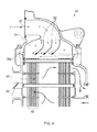
- FIG. 4 shows a heat exchanger 30 according to a second embodiment of the present invention.
- fuel inlet 32 is arranged to deliver the fuel centrally to the fuel inlet cavity 34.
- a plurality of vanes 42 Arranged within the fuel inlet cavity 34 are a plurality of vanes 42 which deflect the fuel entering the cavity and are arranged so as to cause the fuel to swirl within the fuel inlet cavity as shown by the flow arrows F.
- the swirl induced in the fuel entering the heat exchanger 30 causes any entrained ice particles to concentrate in the outer region of the fuel in the fuel inlet cavity 34 and be deposited on the outer wall of the heat exchanger in the region 36a or on the face of the heat exchanger matrix 35 in the outer region of the heat exchanger, thereby continuing to allow fuel to flow through the more central regions of the heat exchanger matrix 35.
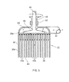
- FIG. 5 shows a heat exchanger 30 according to a third embodiment of the present invention.
- the heat exchanger of this embodiment is substantially the same as that of the first embodiment above, but in addition to the tangentially arranged fuel inlet 32, an impellor 46 is arranged in the fuel inlet cavity 34.
- the impeller 46 is driven through a shaft 44 which is mounted in a bearing 48 and retained in place by a shaft seal 50.
- the impeller 46 imparts rotary motion to the fuel entering and in the fuel inlet cavity 34, thereby causing the desired swirl motion which results in any entrained ice particles concentrating the outer region of the fuel inlet cavity 34 as described in relation to the first embodiment above.
Landscapes
- Engineering & Computer Science (AREA)
- Physics & Mathematics (AREA)
- Mechanical Engineering (AREA)
- General Engineering & Computer Science (AREA)
- Thermal Sciences (AREA)
- Chemical & Material Sciences (AREA)
- Combustion & Propulsion (AREA)
- Geometry (AREA)
- Heat-Exchange Devices With Radiators And Conduit Assemblies (AREA)
- Liquid Carbonaceous Fuels (AREA)
Abstract
Description
- The present invention relates to a heat exchanger and a method of operating a heat exchanger. The invention is particularly, but not exclusively, concerned with a heat exchanger which pre-heats fuel being supplied to a gas turbine and in which the effects of fuel borne ice can be reduced.
- With reference to
Figure 1 , a ducted fan gas turbine engine generally indicated at 10 has a principal and rotational axis X-X. The engine comprises, in axial flow series, anair intake 11, apropulsive fan 12, anintermediate pressure compressor 13, a high-pressure compressor 14,combustion equipment 15, a high-pressure turbine 16, andintermediate pressure turbine 17, a low-pressure turbine 18 and a coreengine exhaust nozzle 19. Anacelle 21 generally surrounds theengine 10 and defines theintake 11, abypass duct 22 and abypass exhaust nozzle1 23. - The
gas turbine engine 10 works in a conventional manner so that air entering theintake 11 is accelerated by thefan 12 to produce two air flows: a first air flow A into theintermediate pressure compressor 14 and a second air flow B which passes through thebypass duct 22 to provide propulsive thrust. Theintermediate pressure compressor 13 compresses the air flow A directed into it before delivering that air to thehigh pressure compressor 14 where further compression takes place. - The compressed air exhausted from the high-
pressure compressor 14 is directed into thecombustion equipment 15 where it is mixed with fuel and the mixture combusted. - The resultant hot combustion products then expand through, and thereby drive the high, intermediate and low-
pressure turbines nozzle 19 to provide additional propulsive thrust. The high, intermediate and low-pressure turbines respectively drive the high andintermediate pressure compressors fan 12 by suitable interconnecting shafts. - The fuel flow supplied to gas turbine engines can contain water. During operation under low ambient temperature operating conditions if the fuel is at a temperature below 0° C, the water will freeze. In these circumstances the fuel will normally enter the engine containing dispersed ice particles in suspension in the fuel. These ice particles present a problem for the fuel system in that they can block small passages and cause fine clearance valves to malfunction.
- This problem is normally overcome by heating the fuel, using heat from the engine oil, via an fuel-oil heat exchanger. A typical arrangement of such a fuel-oil heat exchanger is shown in
Figure 2 . A fuel-oil heat exchanger 30 is arranged in thefuel flow path 60 from the fuel tank (not shown) to theburners 71 of the engine. Fuel passing through the fuel-oil heat exchanger 30 is heated by anoil circuit 80 which supplies hot oil from the engine through surface coolers 81 (or via oil bypass valve 82) to theheat exchanger 30. The heated fuel subsequently passes to thelow pressure filter 65 to the hydro-mechanical unit 68 which performs fuel management functions in response to pilot demand for thrust and controls turbine case cooling (TCC) and the variable stator vane actuator (VSVA). The fuel then passes throughflow meter 69 andhigh pressure filter 70 to theburners 71. - However, if there is ice accumulation in the fuel pipe work supplying the engine, this ice accumulation can break away or "shed" and result in a large quantity of ice arriving at the engine over a short period of time. Such quantities of ice can overwhelm and block the fuel-oil heat exchanger and as a result interrupt the fuel supply causing the fuel system to malfunction and the engine to loose power.
- Prior art systems, for example as shown in
Figure 2 , address this problem by providing abypass valve 64 which provides an alternative route for fuel to reach the engine. If theheat exchanger 30 becomes blocked with ice a pressure operatedbypass valve 64 opens to allow fuel to bypass the blocked heat exchanger and still be supplied to the downstream components 65-71 described above to enable the engine to continue to operate. The heat exchanger fuel side inlet is designed to have sufficient volume to accommodate expected transient quantities of ice, such that when the bypass opens only fuel with the normal (steady state) level of ice concentration will pass to the downstream fuel system components. - However, when the fuel side of the
heat exchanger 30 is blocked and thebypass valve 64 is open, the fuel flow to the downstream components is no longer heated. Such fuel will still contain ice and the continued operation of the engine in this state therefore relies on the ice tolerance of the downstream components. In many cases, these components (in particular units such as filters) will only have a finite capability to deal with the ice content of the fuel. This means that it is important that the ice collected in the heat exchanger inlet melts quickly so that it can properly pass fuel and provide heated fuel with no ice. For example, thelow pressure filter 65 may also need to be provided with abypass valve 66 which operates if the pressure difference across the filter as measured by thepressure sensor 67 becomes too great due to ice accumulation. - Another problem with this arrangement is that it relies on the transiently high level of ice in the fuel to occur over a short period of time, such that all of this ice is captured in the heat exchanger inlet before the bypass is opened, otherwise fuel could be delivered to the downstream components which still contains high concentrations of ice which would cause malfunction of those components.
- Aspects of the present invention seek to address or ameliorate the above problems.
- At its broadest, a first aspect of the present invention provides a heat exchanger in which the fuel entering the heat exchanger is caused to swirl in order to separate any entrained ice. This allows different parts of the heat exchanger to be adapted to deal with the ice whilst fuel with low or zero concentrations of ice continues to pass through the heat exchanger to downstream components.
- Accordingly, a first aspect of the present invention provides a heat exchanger for warming fuel prior to introduction of the fuel to an engine, the heat exchanger including: a fuel inlet and a fuel outlet; a heat exchange matrix having heat transfer components past which the fuel flows between said inlet and said outlet and which are arranged to be heated; and swirl inducing means arranged between said inlet and said matrix arranged to cause fuel from said inlet to swirl prior to entering said matrix.
- By causing the fuel to swirl prior to entering the heat exchange matrix, ice particles entrained in the fuel can be concentrated in a particular area of the heat exchanger thereby leaving other areas of the heat exchanger free from ice particles and allowing fuel which is free of, or which contains a reduced amount of ice, to pass through the heat exchanger and on to downstream fuel system components and the engine.
- Preferably the swirl inducing means is arranged to cause the fuel to swirl about an axis which is substantially parallel to the main direction of fuel flow through said matrix. This action causes ice particles entrained in the fuel to concentrate in outer regions of the heat exchanger and therefore leave a central region of the heat exchanger free from deposited ice particles to permit fuel flow.
- Different forms of the swirl inducing means may be employed. In one embodiment, the swirl inducing means forms part of said fuel inlet and is arranged to cause the fuel to enter the heat exchanger substantially perpendicular to the main direction of fuel flow through said matrix and at a position offset from a central axis of the heat exchanger.
- In one arrangement of this embodiment, the heat exchanger is substantially cylindrical and the swirl inducing means is arranged to cause the fuel to enter the heat exchanger substantially tangentially. A cylindrical configuration of the heat exchanger, at least in the region of the fuel entry, is likely to result in a swirling flow of the fuel which is assisted by the curve of the interior of the heat exchanger and that the swirling flow of the fuel is maintained up to the point at which the fuel enters the heat exchange matrix.
- In another embodiment the swirl inducing means includes a guide vane arranged to cause the fuel to swirl prior to the fuel entering said matrix. The swirl inducing means may include a plurality of such guide vanes. Guide vanes may be used to cause fuel which enters a heat exchanger in standard fashion to swirl. A plurality of guide vanes may be used to improve the uniformity of the swirled fuel flow.
- In another embodiment the swirl inducing means includes a driven element which is arranged to cause the fuel to swirl prior to the fuel entering said matrix. For example the driven element may be an impeller which is arranged to rotate about an axis which is substantially parallel to the main direction of fuel flow through said matrix.
- A driven element as part of the swirl inducing means can ensure that a sufficient velocity of swirling fuel flow is achieved in the heat exchanger, and in particular that the velocity of the swirling fuel flow is not affected by the rate of fuel flow entering the heat exchanger.
- A plurality of different swirl inducing means, including some, all or none of the specific swirl inducing means set out above may be combined in a heat exchanger.
- A second aspect of the present invention provides a gas turbine engine having a heat exchanger according to the above first aspect, including some, all or none of the optional or preferred features of that aspect.
- A gas turbine engine according to this aspect provides for improved resistance to icing in the fuel input to the engine and therefore improved safety in operation and a wider operating range for the engine. The provision of a heat exchanger according to the above first aspect may mean that the ice tolerance of the fuel supply system of the engine downstream of the heat exchanger can be reduced due to the improved ice treatment carried out in the heat exchanger.
- At its broadest, a further aspect of the present invention provides a method of treating fuel, the method including the step of causing fuel to swirl in the early part of a heat exchanger so that entrained ice is concentrated in a specific portion of the fuel flow.
- Accordingly, a third aspect of the present invention provides a method of treating fuel having entrained ice in a heat exchanger, the method including the steps of: causing said fuel to swirl so that the entrained ice concentrates in an outer portion of the fuel flow; passing the swirled fuel through a heat exchanger matrix.
- By causing entrained ice to concentrate in a specific portion of the fuel flow, the heat exchanger can be constructed so as to deal with the concentration of ice in that portion of flow whilst allowing the portion of the fuel flow which has a lower concentration of entrained ice (or no entrained ice) to pass through the heat exchanger and on to the downstream components in the fuel supply system.
- The step of causing the fuel to swirl may cause at least some of the entrained ice to deposit on a surface of the heat exchanger prior to the fuel entering the heat exchanger matrix. This ice may therefore be prevented from entering the heat exchange matrix and blocking it.
- Preferably the method further includes the step of heating the surface on which the ice is deposited so that ice deposited on that surface melts and is subsequently entrained in the fuel flowing through the matrix.
- In one embodiment, the step of causing said fuel to swirl includes causing the fuel to enter the heat exchanger substantially perpendicular to the main direction of fuel flow through said matrix and at a position offset from a central axis of the heat exchanger. In another embodiment the step of causing said fuel to swirl includes mechanical agitation of the fuel.
- Preferably the method of this aspect is carried out using a heat exchanger according to the above first aspect, but this is not required.
- Embodiments of the invention will now be described by way of example with reference to the accompanying drawings in which:
-
Figure 1 shows a schematic longitudinal cross-section through a ducted fan gas turbine engine and has already been described; -
Figure 2 shows a schematic arrangement of a fuel-oil heat exchanger and the associated components in which embodiments of the present invention may be used; -
Figures 3a and 3b respectively show a cross-section through a heat exchanger according to an embodiment of the present invention and an external perspective view of that heat exchanger; -
Figure 4 shows a cross-section through a heat exchanger according to a further embodiment of the present invention; and -
Figure 5 shows a cross-section through a heat exchanger according to a further embodiment of the present invention. -
Figure 2 shows a schematic arrangement of a fuel-oil heat exchanger as used in the fuel supply to a gas turbine engine and the associated components. The main components of this system have already been explained above. In embodiments of the present invention theheat exchanger 30 is a heat exchanger according to the present invention and the by-pass valve 64 can therefore be removed (or, if present, operates only in extreme conditions). -
Figures 3-5 show heat exchangers according to embodiments of the present invention. For ease of reference, the same reference numerals will be used to refer to identical components in each of the embodiments. Where components are substantially identical, but adapted for the specific embodiment, then the same reference numeral will be used but a prime attached to indicate that the components are different. -
Figures 3a and 3b show aheat exchanger 30 according to a first embodiment of the present invention. As shown in the external view ofFigure 3b ,heat exchanger 30 is substantially cylindrical in overall form and has afuel inlet 32 located at one end of the heat exchanger. -
Figure 3a shows a cross section through the central plane of theheat exchanger 30. The direction of fuel movement through the heat exchanger is shown byarrows F. Walls 36 enclose the components of the heat exchanger. In the interior of theheat exchanger 30 there is afuel inlet cavity 34 and a heat-exchanger matrix 35. Theheat exchanger matrix 35 may be in any known form, but in this embodiment comprises a plurality oftubes 40 and a plurality ofpassages 38 around the tubes. Thetubes 40 allow fuel to pass from the fuel inlet cavity through the heat-exchanger whilst hot oil from the engine is passed around the outside of thetubes 40 through thepassages 38 so as to warm the fuel passing throughtubes 40. - The
fuel inlet 32 of theheat exchanger 30 of this embodiment is arranged so that the fuel is caused to enter the interior of the heat exchanger substantially tangentially to the radius of the body of the heat exchanger. This causes the fuel entering thefuel inlet cavity 34 to swirl as shown by the flow arrows inFigure 3a prior to entering theheat exchanger matrix 35. - The swirling motion of the fuel in the
fuel inlet cavity 34 subjects the fuel to a centrifugal force. Since the density of any entrained ice particles in the fuel will be higher than that of the fuel itself, this centrifugal force causes the entrained ice particles to concentrate in the outer region of the fuel inlet cavity 34 (i.e. that closest to wall 36). This concentration of ice particles towards the outer regions of thefuel inlet cavity 34 will result in any ice particles being deposited on the wall of the heat exchanger in theregion 36a and on the outer region of the face of theheat exchanger matrix 35, for example over the entrance totubes 40a. - As a result, at least the central region of the
heat exchanger matrix 35, such astubes 40b, will remain clear of ice particles and fuel will flow through the heat exchanger matrix, be heated by the hot oil flowing throughpassages 38 and pass onwards towards the engine. - The ice particles deposited on the wall of the heat exchanger in the
region 36a and on the outer region of the face of theheat exchanger matrix 35 in the vicinity ofpassages 40a will continue to receive heat from the hot oil passing through the heat exchanger (in particular oil that passes throughpassage 38a closest to the wall 36) and will eventually melt and pass through theheat exchanger matrix 35 as liquid water and be re-entrained in the fuel flow. - Ice can therefore be prevented from entering fuel system components downstream of the
heat exchanger 30 by the swirl induced in the fuel flow prior to passing through theheat exchanger matrix 35. Furthermore, even if there is a build up of ice, this will occur on the outer regions of theheat exchanger matrix 35 and fuel will continue to flow through thetubes 40b in the central region of theheat exchanger matrix 35 and be supplied to the downstream fuel system components. Therefore there may be no need for a by-pass valve to be present to allow fuel to by-pass theheat exchanger 30 or, alternatively, if present, such a by-pass valve will only operate in extreme conditions of icing. -
Figure 4 shows aheat exchanger 30 according to a second embodiment of the present invention. In this embodiment,fuel inlet 32 is arranged to deliver the fuel centrally to thefuel inlet cavity 34. Arranged within thefuel inlet cavity 34 are a plurality ofvanes 42 which deflect the fuel entering the cavity and are arranged so as to cause the fuel to swirl within the fuel inlet cavity as shown by the flow arrows F. - Again the swirl induced in the fuel entering the
heat exchanger 30 causes any entrained ice particles to concentrate in the outer region of the fuel in thefuel inlet cavity 34 and be deposited on the outer wall of the heat exchanger in theregion 36a or on the face of theheat exchanger matrix 35 in the outer region of the heat exchanger, thereby continuing to allow fuel to flow through the more central regions of theheat exchanger matrix 35. - In the embodiment shown in
Figure 4 , a different arrangement ofheat exchanger matrix 35 is provided. In this arrangement the fuel passes through the matrix in a plurality of tubes 40' around which hot oil from the engine flows through passages 38'. -
Figure 5 shows aheat exchanger 30 according to a third embodiment of the present invention. The heat exchanger of this embodiment is substantially the same as that of the first embodiment above, but in addition to the tangentially arrangedfuel inlet 32, animpellor 46 is arranged in thefuel inlet cavity 34. Theimpeller 46 is driven through ashaft 44 which is mounted in abearing 48 and retained in place by ashaft seal 50. Theimpeller 46 imparts rotary motion to the fuel entering and in thefuel inlet cavity 34, thereby causing the desired swirl motion which results in any entrained ice particles concentrating the outer region of thefuel inlet cavity 34 as described in relation to the first embodiment above. - While the invention has been described in conjunction with the exemplary embodiments described above, many equivalent modifications and variations will be apparent to those skilled in the art when given this disclosure. Accordingly, the exemplary embodiments of the invention set forth above are considered to be illustrative and not limiting. Various changes to the described embodiments may be made without departing from the spirit and scope of the invention.
- In particular, it will be appreciated that further embodiments of the present invention may use some, all or none of the above described arrangements for causing the fuel entering the heat exchanger to swirl prior to entering the heat exchanger matrix, thereby causing entrained ice particles to move to the outer region of the heat exchanger and continuing to permit fuel flow through more central regions of the heat exchanger matrix.
- All references referred to above are hereby incorporated by reference.
Claims (13)
- A heat exchanger (30) for warming fuel prior to introduction of the fuel to an engine, the heat exchanger including:a fuel inlet (32), a fuel outlet and a fuel inlet cavity (34) located therebetween;a heat exchange matrix (35) having heat transfer components past which the fuel flows between said fuel inlet cavity (34) and said outlet and which are arranged to be heated, the heat transfer components comprising a plurality of fuel tubes (40) between the fuel inlet cavity (34) and the outlet; andswirl inducing means (42, 46) arranged within said fuel inlet cavity (34) between said inlet (32) and said plurality of fuel tubes (40) arranged to cause fuel from said inlet (32) to swirl prior to entering said plurality of fuel tubes (40).
- A heat exchanger according to claim 1 wherein the swirl inducing means (46) is arranged to cause the fuel to swirl about an axis which is substantially parallel to the main direction of fuel flow through said matrix (35).
- A heat exchanger according to claim 1 or claim 2 wherein the swirl inducing means (42) forms part of said fuel inlet (32) and is arranged to cause the fuel to enter the heat exchanger (30) substantially perpendicular to the main direction of fuel flow through said matrix (35) and at a position offset from a central axis of the heat exchanger (30).
- A heat exchanger according to claim 3 wherein the heat exchanger (30) is substantially cylindrical and the swirl inducing means (42) is arranged to cause the fuel to enter the heat exchanger (30) substantially tangentially.
- A heat exchanger according to any one of claims 1 to 4 wherein the swirl inducing (42) means includes a guide vane (42) arranged to cause the fuel to swirl prior to the fuel entering said matrix (35).
- A heat exchanger according to any one of claims 1 to 5 wherein the swirl inducing means (46) includes a driven element (46) which is arranged to cause the fuel to swirl prior to the fuel entering said matrix (35).
- A heat exchanger according to claim 6 wherein the driven element (46) is an impeller (46) which is arranged to rotate about an axis which is substantially parallel to the main direction of fuel flow through said matrix (35).
- A gas turbine engine having a heat exchanger (30) according to any one of the preceding claims.
- A method of treating fuel having entrained ice in a heat exchanger, the method including the steps of:causing said fuel to swirl so that the entrained ice concentrates in an outer portion of the fuel flow;passing the swirled fuel through a heat exchanger matrix (35).
- A method according to claim 9 wherein the step of causing the fuel to swirl causes at least some of the entrained ice to deposit on a surface of the heat exchanger (35) prior to the fuel entering the heat exchanger matrix (35).
- A method according to claim 10 further including the step of heating the surface on which the ice is deposited so that ice deposited on that surface melts and is subsequently entrained in the fuel flowing through the matrix (35).
- A method according to any one of claims 9 to 11 wherein the step of causing said fuel to swirl includes causing the fuel to enter the heat exchanger (35) substantially perpendicular to the main direction of fuel flow through said matrix (35) and at a position offset from a central axis of the heat exchanger (30).
- A method according to any one of claims 9 to 12 wherein the step of causing said fuel to swirl includes mechanical agitation of the fuel.
Applications Claiming Priority (1)
| Application Number | Priority Date | Filing Date | Title |
|---|---|---|---|
| GBGB1110796.8A GB201110796D0 (en) | 2011-06-27 | 2011-06-27 | Heat exchanger |
Publications (2)
| Publication Number | Publication Date |
|---|---|
| EP2541180A1 true EP2541180A1 (en) | 2013-01-02 |
| EP2541180B1 EP2541180B1 (en) | 2015-12-09 |
Family
ID=44485156
Family Applications (1)
| Application Number | Title | Priority Date | Filing Date |
|---|---|---|---|
| EP12172200.3A Not-in-force EP2541180B1 (en) | 2011-06-27 | 2012-06-15 | Heat exchanger |
Country Status (3)
| Country | Link |
|---|---|
| US (1) | US8661783B2 (en) |
| EP (1) | EP2541180B1 (en) |
| GB (1) | GB201110796D0 (en) |
Cited By (5)
| Publication number | Priority date | Publication date | Assignee | Title |
|---|---|---|---|---|
| WO2015053824A1 (en) | 2013-10-09 | 2015-04-16 | United Technologies Corporation | Thermal management system manifold |
| EP3051246A1 (en) * | 2013-11-14 | 2016-08-03 | Sumitomo Precision Products Co., Ltd. | Heat exchanger for aircrafts |
| EP2971683A4 (en) * | 2013-03-14 | 2016-11-23 | United Technologies Corp | Gas turbine engine heat exchanger manifold |
| EP3348947A1 (en) * | 2017-01-13 | 2018-07-18 | HS Marston Aerospace Limited | Heat exchanger |
| EP3992565A1 (en) * | 2020-10-28 | 2022-05-04 | B/E Aerospace, Inc. | Heat exchanger manifold |
Families Citing this family (15)
| Publication number | Priority date | Publication date | Assignee | Title |
|---|---|---|---|---|
| WO2015002716A1 (en) * | 2013-07-03 | 2015-01-08 | United Technologies Corporation | Electrically heated filter screens |
| US9823030B2 (en) | 2013-08-14 | 2017-11-21 | Hamilton Sundstrand Corporation | Heated bypass valve for heat exchanger |
| EP3044443B1 (en) * | 2013-09-10 | 2018-08-08 | United Technologies Corporation | Fuel management system for a turbine engine |
| US10830543B2 (en) | 2015-02-06 | 2020-11-10 | Raytheon Technologies Corporation | Additively manufactured ducted heat exchanger system with additively manufactured header |
| US10809016B2 (en) | 2015-02-06 | 2020-10-20 | Raytheon Technologies Corporation | Heat exchanger system with additively manufactured heat transfer tube that follows a non-linear path |
| US10907500B2 (en) | 2015-02-06 | 2021-02-02 | Raytheon Technologies Corporation | Heat exchanger system with spatially varied additively manufactured heat transfer surfaces |
| US10443503B2 (en) * | 2015-03-27 | 2019-10-15 | Pratt & Whitney Canada Corp. | Fuel system for a gas turbine engine |
| US10578020B2 (en) * | 2015-07-21 | 2020-03-03 | Unison Industries, Llc | Integral oil tank heat exchanger |
| EP3309494B1 (en) * | 2016-10-13 | 2021-04-28 | HS Marston Aerospace Limited | Heat exchanger |
| US10670349B2 (en) | 2017-07-18 | 2020-06-02 | General Electric Company | Additively manufactured heat exchanger |
| US10502232B2 (en) * | 2018-03-01 | 2019-12-10 | Garrett Transportation I Inc. | Turbocharger compressor having adjustable trim mechanism including swirl inducers |
| FR3116858B1 (en) * | 2020-12-01 | 2022-10-28 | Safran Aircraft Engines | AIRCRAFT TURBOMACHINE ASSEMBLY INCLUDING PASSIVE FUEL/OIL HEAT EXCHANGER BYPASS VALVE |
| GB202319154D0 (en) * | 2023-12-14 | 2024-01-31 | Rolls Royce Plc | Gas turbine engine |
| GB202319150D0 (en) * | 2023-12-14 | 2024-01-31 | Rolls Royce Plc | Fueldraulic heat management system |
| GB202319159D0 (en) | 2023-12-14 | 2024-01-31 | Rolls Royce Plc | Fueldraulic actuation |
Citations (6)
| Publication number | Priority date | Publication date | Assignee | Title |
|---|---|---|---|---|
| DE317680C (en) * | ||||
| US2925712A (en) * | 1952-12-12 | 1960-02-23 | Rolls Royce | Aircraft fuel system with fuel heating means |
| US4759401A (en) * | 1984-11-29 | 1988-07-26 | Parker-Hannifin Corporation | Three fluid heat exchanger for cooling oil and air with fuel |
| JP2007046890A (en) * | 2005-07-12 | 2007-02-22 | Usui Kokusai Sangyo Kaisha Ltd | Tubular heat exchanger for egr gas cooler |
| US20100243208A1 (en) * | 2009-03-17 | 2010-09-30 | Kar Kishore K | Tube-side sequentially pulsable-flow shell-and-tube heat exchanger appratus, system, and method |
| DE102010025998A1 (en) * | 2010-07-03 | 2012-03-29 | Mtu Aero Engines Gmbh | Profile heat exchanger, particularly for gas turbine, has a supply passage, discharge passage and multiple hollow sections, particularly elongated, oval or elliptical shaped cross sections |
Family Cites Families (8)
| Publication number | Priority date | Publication date | Assignee | Title |
|---|---|---|---|---|
| US2988335A (en) * | 1958-03-06 | 1961-06-13 | Gen Motors Corp | Heat exchangers |
| US3557557A (en) * | 1969-11-24 | 1971-01-26 | Gen Motors Corp | Engine air precooler and ice eliminator |
| US4832114A (en) * | 1987-12-02 | 1989-05-23 | Yeh Hsu Chieh | Device for producing high heat transfer in heat exchanger tubes |
| GB2276231B (en) | 1993-03-19 | 1997-02-05 | Hick Hargreaves & Co Ltd | Fluid flow distribution device |
| DE4325977A1 (en) | 1993-08-03 | 1995-02-09 | Balcke Duerr Ag | Diffuser |
| US6440317B1 (en) * | 1996-03-18 | 2002-08-27 | Fuel Dynamics | Cyclonic ice separation for low temperature jet fuels |
| KR100809081B1 (en) | 2006-11-07 | 2008-03-03 | 김종헌 | Soot Reduction and Fuel Saver for Diesel Engine |
| SE531857C2 (en) * | 2007-12-21 | 2009-08-25 | Volvo Aero Corp | A component designed to be exposed to high thermal load during operation |
-
2011
- 2011-06-27 GB GBGB1110796.8A patent/GB201110796D0/en not_active Ceased
-
2012
- 2012-06-15 US US13/524,460 patent/US8661783B2/en active Active
- 2012-06-15 EP EP12172200.3A patent/EP2541180B1/en not_active Not-in-force
Patent Citations (6)
| Publication number | Priority date | Publication date | Assignee | Title |
|---|---|---|---|---|
| DE317680C (en) * | ||||
| US2925712A (en) * | 1952-12-12 | 1960-02-23 | Rolls Royce | Aircraft fuel system with fuel heating means |
| US4759401A (en) * | 1984-11-29 | 1988-07-26 | Parker-Hannifin Corporation | Three fluid heat exchanger for cooling oil and air with fuel |
| JP2007046890A (en) * | 2005-07-12 | 2007-02-22 | Usui Kokusai Sangyo Kaisha Ltd | Tubular heat exchanger for egr gas cooler |
| US20100243208A1 (en) * | 2009-03-17 | 2010-09-30 | Kar Kishore K | Tube-side sequentially pulsable-flow shell-and-tube heat exchanger appratus, system, and method |
| DE102010025998A1 (en) * | 2010-07-03 | 2012-03-29 | Mtu Aero Engines Gmbh | Profile heat exchanger, particularly for gas turbine, has a supply passage, discharge passage and multiple hollow sections, particularly elongated, oval or elliptical shaped cross sections |
Cited By (12)
| Publication number | Priority date | Publication date | Assignee | Title |
|---|---|---|---|---|
| EP2971683A4 (en) * | 2013-03-14 | 2016-11-23 | United Technologies Corp | Gas turbine engine heat exchanger manifold |
| US10316754B2 (en) | 2013-03-14 | 2019-06-11 | United Technologies Corporation | Gas turbine engine heat exchanger manifold |
| WO2015053824A1 (en) | 2013-10-09 | 2015-04-16 | United Technologies Corporation | Thermal management system manifold |
| EP3055534A4 (en) * | 2013-10-09 | 2017-06-07 | United Technologies Corporation | Thermal management system manifold |
| US10253693B2 (en) | 2013-10-09 | 2019-04-09 | United Technologies Corporation | Thermal management system manifold |
| EP3051246A1 (en) * | 2013-11-14 | 2016-08-03 | Sumitomo Precision Products Co., Ltd. | Heat exchanger for aircrafts |
| EP2924385A4 (en) * | 2013-11-14 | 2017-03-15 | Sumitomo Precision Products Co., Ltd. | Heat exchanger for aircraft |
| EP3348947A1 (en) * | 2017-01-13 | 2018-07-18 | HS Marston Aerospace Limited | Heat exchanger |
| US11029102B2 (en) | 2017-01-13 | 2021-06-08 | Hs Marston Aerospace Limited | Heat exchanger |
| US12061055B2 (en) | 2017-01-13 | 2024-08-13 | Hs Marston Aerospace Limited | Heat exchanger |
| EP3992565A1 (en) * | 2020-10-28 | 2022-05-04 | B/E Aerospace, Inc. | Heat exchanger manifold |
| US12416458B2 (en) | 2020-10-28 | 2025-09-16 | B/E Aerospace, Inc. | Heat exchanger manifold |
Also Published As
| Publication number | Publication date |
|---|---|
| GB201110796D0 (en) | 2011-08-10 |
| US20120324859A1 (en) | 2012-12-27 |
| US8661783B2 (en) | 2014-03-04 |
| EP2541180B1 (en) | 2015-12-09 |
Similar Documents
| Publication | Publication Date | Title |
|---|---|---|
| US8661783B2 (en) | Heat exchanger having swirling means | |
| RU2709761C2 (en) | Turbine engine oil circuit cooling | |
| US9739198B2 (en) | Oil and fuel circuits in a turbine engine | |
| CN109424440B (en) | Method of cooling and pressurizing a gas turbine engine and one or more components thereof | |
| US10926884B2 (en) | Two mode system that provides bleed and outside air or just outside air | |
| CN104514636B (en) | The method for operating more packet environmental control systems | |
| US9145774B2 (en) | Method for cooling a gas turbine plant and gas turbine plant for implementing the method | |
| EP3318743B1 (en) | Intercooled cooled cooling integrated air cycle machine | |
| US11053010B2 (en) | Aircraft environmental control system | |
| US20160281603A1 (en) | Gas turbine engine fluid heat management system | |
| CN104420999B (en) | For the system and method to the deicing of gas-turbine unit inlet screen and to inlet air filter dehumidifying | |
| CN108071490B (en) | Cooling systems for turbine engines | |
| CN105378232B (en) | For the oily method in the oil cooler of turbine engine, turbine engine and cooling turbine engine | |
| CN106907192A (en) | thermal management system | |
| US10006365B2 (en) | Air supply and conditioning system for a gas turbine | |
| EP2660431A2 (en) | Gas turbomachine including a counter-flow cooling system and method | |
| US20130036722A1 (en) | Fuel system having fuel control unit and heat exchanger | |
| CN114954965A (en) | Aircraft with dihydro-based cooling system and engine | |
| US12097962B2 (en) | Aircraft environmental control system | |
| US20220275733A1 (en) | Ejector driven scavenge system for particle separator associated with gas turbine engine | |
| US12139260B2 (en) | Ambient air architecture with single ACM without an ambient turbine | |
| EP3835208B1 (en) | Bootstrap air cycle with vapor power turbine | |
| CN207660707U (en) | The multipart anti-icing system of aero-engine | |
| EP3287620B1 (en) | Boost compressor for engine cooling circuit driven by low spool | |
| EP2310652B1 (en) | Gas turbine engine and integrated heat exchange system |
Legal Events
| Date | Code | Title | Description |
|---|---|---|---|
| PUAI | Public reference made under article 153(3) epc to a published international application that has entered the european phase |
Free format text: ORIGINAL CODE: 0009012 |
|
| AK | Designated contracting states |
Kind code of ref document: A1 Designated state(s): AL AT BE BG CH CY CZ DE DK EE ES FI FR GB GR HR HU IE IS IT LI LT LU LV MC MK MT NL NO PL PT RO RS SE SI SK SM TR |
|
| AX | Request for extension of the european patent |
Extension state: BA ME |
|
| 17P | Request for examination filed |
Effective date: 20130702 |
|
| RBV | Designated contracting states (corrected) |
Designated state(s): AL AT BE BG CH CY CZ DE DK EE ES FI FR GB GR HR HU IE IS IT LI LT LU LV MC MK MT NL NO PL PT RO RS SE SI SK SM TR |
|
| 17Q | First examination report despatched |
Effective date: 20131113 |
|
| RAP1 | Party data changed (applicant data changed or rights of an application transferred) |
Owner name: ROLLS-ROYCE PLC |
|
| GRAP | Despatch of communication of intention to grant a patent |
Free format text: ORIGINAL CODE: EPIDOSNIGR1 |
|
| GRAS | Grant fee paid |
Free format text: ORIGINAL CODE: EPIDOSNIGR3 |
|
| INTG | Intention to grant announced |
Effective date: 20151001 |
|
| GRAA | (expected) grant |
Free format text: ORIGINAL CODE: 0009210 |
|
| AK | Designated contracting states |
Kind code of ref document: B1 Designated state(s): AL AT BE BG CH CY CZ DE DK EE ES FI FR GB GR HR HU IE IS IT LI LT LU LV MC MK MT NL NO PL PT RO RS SE SI SK SM TR |
|
| REG | Reference to a national code |
Ref country code: GB Ref legal event code: FG4D |
|
| REG | Reference to a national code |
Ref country code: AT Ref legal event code: REF Ref document number: 764777 Country of ref document: AT Kind code of ref document: T Effective date: 20151215 Ref country code: CH Ref legal event code: EP |
|
| REG | Reference to a national code |
Ref country code: IE Ref legal event code: FG4D |
|
| REG | Reference to a national code |
Ref country code: DE Ref legal event code: R096 Ref document number: 602012012830 Country of ref document: DE |
|
| REG | Reference to a national code |
Ref country code: LT Ref legal event code: MG4D |
|
| REG | Reference to a national code |
Ref country code: NL Ref legal event code: MP Effective date: 20151209 |
|
| PG25 | Lapsed in a contracting state [announced via postgrant information from national office to epo] |
Ref country code: ES Free format text: LAPSE BECAUSE OF FAILURE TO SUBMIT A TRANSLATION OF THE DESCRIPTION OR TO PAY THE FEE WITHIN THE PRESCRIBED TIME-LIMIT Effective date: 20151209 Ref country code: LT Free format text: LAPSE BECAUSE OF FAILURE TO SUBMIT A TRANSLATION OF THE DESCRIPTION OR TO PAY THE FEE WITHIN THE PRESCRIBED TIME-LIMIT Effective date: 20151209 Ref country code: NO Free format text: LAPSE BECAUSE OF FAILURE TO SUBMIT A TRANSLATION OF THE DESCRIPTION OR TO PAY THE FEE WITHIN THE PRESCRIBED TIME-LIMIT Effective date: 20160309 |
|
| REG | Reference to a national code |
Ref country code: AT Ref legal event code: MK05 Ref document number: 764777 Country of ref document: AT Kind code of ref document: T Effective date: 20151209 |
|
| REG | Reference to a national code |
Ref country code: DE Ref legal event code: R082 Ref document number: 602012012830 Country of ref document: DE Representative=s name: HERNANDEZ, YORCK, DIPL.-ING., DE |
|
| PG25 | Lapsed in a contracting state [announced via postgrant information from national office to epo] |
Ref country code: LV Free format text: LAPSE BECAUSE OF FAILURE TO SUBMIT A TRANSLATION OF THE DESCRIPTION OR TO PAY THE FEE WITHIN THE PRESCRIBED TIME-LIMIT Effective date: 20151209 Ref country code: SE Free format text: LAPSE BECAUSE OF FAILURE TO SUBMIT A TRANSLATION OF THE DESCRIPTION OR TO PAY THE FEE WITHIN THE PRESCRIBED TIME-LIMIT Effective date: 20151209 Ref country code: NL Free format text: LAPSE BECAUSE OF FAILURE TO SUBMIT A TRANSLATION OF THE DESCRIPTION OR TO PAY THE FEE WITHIN THE PRESCRIBED TIME-LIMIT Effective date: 20151209 Ref country code: RS Free format text: LAPSE BECAUSE OF FAILURE TO SUBMIT A TRANSLATION OF THE DESCRIPTION OR TO PAY THE FEE WITHIN THE PRESCRIBED TIME-LIMIT Effective date: 20151209 Ref country code: FI Free format text: LAPSE BECAUSE OF FAILURE TO SUBMIT A TRANSLATION OF THE DESCRIPTION OR TO PAY THE FEE WITHIN THE PRESCRIBED TIME-LIMIT Effective date: 20151209 Ref country code: GR Free format text: LAPSE BECAUSE OF FAILURE TO SUBMIT A TRANSLATION OF THE DESCRIPTION OR TO PAY THE FEE WITHIN THE PRESCRIBED TIME-LIMIT Effective date: 20160310 |
|
| REG | Reference to a national code |
Ref country code: FR Ref legal event code: PLFP Year of fee payment: 5 |
|
| PG25 | Lapsed in a contracting state [announced via postgrant information from national office to epo] |
Ref country code: IS Free format text: LAPSE BECAUSE OF FAILURE TO SUBMIT A TRANSLATION OF THE DESCRIPTION OR TO PAY THE FEE WITHIN THE PRESCRIBED TIME-LIMIT Effective date: 20151209 |
|
| PG25 | Lapsed in a contracting state [announced via postgrant information from national office to epo] |
Ref country code: CZ Free format text: LAPSE BECAUSE OF FAILURE TO SUBMIT A TRANSLATION OF THE DESCRIPTION OR TO PAY THE FEE WITHIN THE PRESCRIBED TIME-LIMIT Effective date: 20151209 Ref country code: IT Free format text: LAPSE BECAUSE OF FAILURE TO SUBMIT A TRANSLATION OF THE DESCRIPTION OR TO PAY THE FEE WITHIN THE PRESCRIBED TIME-LIMIT Effective date: 20151209 |
|
| PG25 | Lapsed in a contracting state [announced via postgrant information from national office to epo] |
Ref country code: RO Free format text: LAPSE BECAUSE OF FAILURE TO SUBMIT A TRANSLATION OF THE DESCRIPTION OR TO PAY THE FEE WITHIN THE PRESCRIBED TIME-LIMIT Effective date: 20151209 Ref country code: IS Free format text: LAPSE BECAUSE OF FAILURE TO SUBMIT A TRANSLATION OF THE DESCRIPTION OR TO PAY THE FEE WITHIN THE PRESCRIBED TIME-LIMIT Effective date: 20160409 Ref country code: EE Free format text: LAPSE BECAUSE OF FAILURE TO SUBMIT A TRANSLATION OF THE DESCRIPTION OR TO PAY THE FEE WITHIN THE PRESCRIBED TIME-LIMIT Effective date: 20151209 Ref country code: SK Free format text: LAPSE BECAUSE OF FAILURE TO SUBMIT A TRANSLATION OF THE DESCRIPTION OR TO PAY THE FEE WITHIN THE PRESCRIBED TIME-LIMIT Effective date: 20151209 Ref country code: PT Free format text: LAPSE BECAUSE OF FAILURE TO SUBMIT A TRANSLATION OF THE DESCRIPTION OR TO PAY THE FEE WITHIN THE PRESCRIBED TIME-LIMIT Effective date: 20160411 Ref country code: AT Free format text: LAPSE BECAUSE OF FAILURE TO SUBMIT A TRANSLATION OF THE DESCRIPTION OR TO PAY THE FEE WITHIN THE PRESCRIBED TIME-LIMIT Effective date: 20151209 Ref country code: SM Free format text: LAPSE BECAUSE OF FAILURE TO SUBMIT A TRANSLATION OF THE DESCRIPTION OR TO PAY THE FEE WITHIN THE PRESCRIBED TIME-LIMIT Effective date: 20151209 |
|
| REG | Reference to a national code |
Ref country code: DE Ref legal event code: R097 Ref document number: 602012012830 Country of ref document: DE |
|
| PLBE | No opposition filed within time limit |
Free format text: ORIGINAL CODE: 0009261 |
|
| STAA | Information on the status of an ep patent application or granted ep patent |
Free format text: STATUS: NO OPPOSITION FILED WITHIN TIME LIMIT |
|
| PG25 | Lapsed in a contracting state [announced via postgrant information from national office to epo] |
Ref country code: DK Free format text: LAPSE BECAUSE OF FAILURE TO SUBMIT A TRANSLATION OF THE DESCRIPTION OR TO PAY THE FEE WITHIN THE PRESCRIBED TIME-LIMIT Effective date: 20151209 Ref country code: PL Free format text: LAPSE BECAUSE OF FAILURE TO SUBMIT A TRANSLATION OF THE DESCRIPTION OR TO PAY THE FEE WITHIN THE PRESCRIBED TIME-LIMIT Effective date: 20151209 |
|
| 26N | No opposition filed |
Effective date: 20160912 |
|
| PG25 | Lapsed in a contracting state [announced via postgrant information from national office to epo] |
Ref country code: SI Free format text: LAPSE BECAUSE OF FAILURE TO SUBMIT A TRANSLATION OF THE DESCRIPTION OR TO PAY THE FEE WITHIN THE PRESCRIBED TIME-LIMIT Effective date: 20151209 |
|
| PG25 | Lapsed in a contracting state [announced via postgrant information from national office to epo] |
Ref country code: BE Free format text: LAPSE BECAUSE OF FAILURE TO SUBMIT A TRANSLATION OF THE DESCRIPTION OR TO PAY THE FEE WITHIN THE PRESCRIBED TIME-LIMIT Effective date: 20151209 |
|
| PG25 | Lapsed in a contracting state [announced via postgrant information from national office to epo] |
Ref country code: MC Free format text: LAPSE BECAUSE OF FAILURE TO SUBMIT A TRANSLATION OF THE DESCRIPTION OR TO PAY THE FEE WITHIN THE PRESCRIBED TIME-LIMIT Effective date: 20151209 |
|
| REG | Reference to a national code |
Ref country code: CH Ref legal event code: PL |
|
| REG | Reference to a national code |
Ref country code: IE Ref legal event code: MM4A |
|
| PG25 | Lapsed in a contracting state [announced via postgrant information from national office to epo] |
Ref country code: CH Free format text: LAPSE BECAUSE OF NON-PAYMENT OF DUE FEES Effective date: 20160630 Ref country code: LI Free format text: LAPSE BECAUSE OF NON-PAYMENT OF DUE FEES Effective date: 20160630 |
|
| PG25 | Lapsed in a contracting state [announced via postgrant information from national office to epo] |
Ref country code: IE Free format text: LAPSE BECAUSE OF NON-PAYMENT OF DUE FEES Effective date: 20160615 |
|
| REG | Reference to a national code |
Ref country code: FR Ref legal event code: PLFP Year of fee payment: 6 |
|
| PG25 | Lapsed in a contracting state [announced via postgrant information from national office to epo] |
Ref country code: HU Free format text: LAPSE BECAUSE OF FAILURE TO SUBMIT A TRANSLATION OF THE DESCRIPTION OR TO PAY THE FEE WITHIN THE PRESCRIBED TIME-LIMIT; INVALID AB INITIO Effective date: 20120615 Ref country code: CY Free format text: LAPSE BECAUSE OF FAILURE TO SUBMIT A TRANSLATION OF THE DESCRIPTION OR TO PAY THE FEE WITHIN THE PRESCRIBED TIME-LIMIT Effective date: 20151209 |
|
| REG | Reference to a national code |
Ref country code: FR Ref legal event code: PLFP Year of fee payment: 7 |
|
| PG25 | Lapsed in a contracting state [announced via postgrant information from national office to epo] |
Ref country code: LU Free format text: LAPSE BECAUSE OF NON-PAYMENT OF DUE FEES Effective date: 20160615 Ref country code: HR Free format text: LAPSE BECAUSE OF FAILURE TO SUBMIT A TRANSLATION OF THE DESCRIPTION OR TO PAY THE FEE WITHIN THE PRESCRIBED TIME-LIMIT Effective date: 20151209 Ref country code: TR Free format text: LAPSE BECAUSE OF FAILURE TO SUBMIT A TRANSLATION OF THE DESCRIPTION OR TO PAY THE FEE WITHIN THE PRESCRIBED TIME-LIMIT Effective date: 20151209 Ref country code: MK Free format text: LAPSE BECAUSE OF FAILURE TO SUBMIT A TRANSLATION OF THE DESCRIPTION OR TO PAY THE FEE WITHIN THE PRESCRIBED TIME-LIMIT Effective date: 20151209 Ref country code: MT Free format text: LAPSE BECAUSE OF NON-PAYMENT OF DUE FEES Effective date: 20160630 |
|
| PG25 | Lapsed in a contracting state [announced via postgrant information from national office to epo] |
Ref country code: BG Free format text: LAPSE BECAUSE OF FAILURE TO SUBMIT A TRANSLATION OF THE DESCRIPTION OR TO PAY THE FEE WITHIN THE PRESCRIBED TIME-LIMIT Effective date: 20151209 |
|
| PG25 | Lapsed in a contracting state [announced via postgrant information from national office to epo] |
Ref country code: AL Free format text: LAPSE BECAUSE OF FAILURE TO SUBMIT A TRANSLATION OF THE DESCRIPTION OR TO PAY THE FEE WITHIN THE PRESCRIBED TIME-LIMIT Effective date: 20151209 |
|
| PGFP | Annual fee paid to national office [announced via postgrant information from national office to epo] |
Ref country code: FR Payment date: 20190625 Year of fee payment: 8 |
|
| PGFP | Annual fee paid to national office [announced via postgrant information from national office to epo] |
Ref country code: DE Payment date: 20190627 Year of fee payment: 8 Ref country code: GB Payment date: 20190627 Year of fee payment: 8 |
|
| REG | Reference to a national code |
Ref country code: DE Ref legal event code: R119 Ref document number: 602012012830 Country of ref document: DE |
|
| GBPC | Gb: european patent ceased through non-payment of renewal fee |
Effective date: 20200615 |
|
| PG25 | Lapsed in a contracting state [announced via postgrant information from national office to epo] |
Ref country code: GB Free format text: LAPSE BECAUSE OF NON-PAYMENT OF DUE FEES Effective date: 20200615 Ref country code: FR Free format text: LAPSE BECAUSE OF NON-PAYMENT OF DUE FEES Effective date: 20200630 |
|
| PG25 | Lapsed in a contracting state [announced via postgrant information from national office to epo] |
Ref country code: DE Free format text: LAPSE BECAUSE OF NON-PAYMENT OF DUE FEES Effective date: 20210101 |