EP2541063A1 - Electric compressor, and method for assembling same - Google Patents
Electric compressor, and method for assembling same Download PDFInfo
- Publication number
- EP2541063A1 EP2541063A1 EP10846573A EP10846573A EP2541063A1 EP 2541063 A1 EP2541063 A1 EP 2541063A1 EP 10846573 A EP10846573 A EP 10846573A EP 10846573 A EP10846573 A EP 10846573A EP 2541063 A1 EP2541063 A1 EP 2541063A1
- Authority
- EP
- European Patent Office
- Prior art keywords
- press
- bearing
- rotor
- fitting
- main
- Prior art date
- Legal status (The legal status is an assumption and is not a legal conclusion. Google has not performed a legal analysis and makes no representation as to the accuracy of the status listed.)
- Granted
Links
Images



Classifications
-
- F—MECHANICAL ENGINEERING; LIGHTING; HEATING; WEAPONS; BLASTING
- F04—POSITIVE - DISPLACEMENT MACHINES FOR LIQUIDS; PUMPS FOR LIQUIDS OR ELASTIC FLUIDS
- F04B—POSITIVE-DISPLACEMENT MACHINES FOR LIQUIDS; PUMPS
- F04B39/00—Component parts, details, or accessories, of pumps or pumping systems specially adapted for elastic fluids, not otherwise provided for in, or of interest apart from, groups F04B25/00 - F04B37/00
- F04B39/14—Provisions for readily assembling or disassembling
-
- F—MECHANICAL ENGINEERING; LIGHTING; HEATING; WEAPONS; BLASTING
- F04—POSITIVE - DISPLACEMENT MACHINES FOR LIQUIDS; PUMPS FOR LIQUIDS OR ELASTIC FLUIDS
- F04C—ROTARY-PISTON, OR OSCILLATING-PISTON, POSITIVE-DISPLACEMENT MACHINES FOR LIQUIDS; ROTARY-PISTON, OR OSCILLATING-PISTON, POSITIVE-DISPLACEMENT PUMPS
- F04C18/00—Rotary-piston pumps specially adapted for elastic fluids
- F04C18/02—Rotary-piston pumps specially adapted for elastic fluids of arcuate-engagement type, i.e. with circular translatory movement of co-operating members, each member having the same number of teeth or tooth-equivalents
- F04C18/0207—Rotary-piston pumps specially adapted for elastic fluids of arcuate-engagement type, i.e. with circular translatory movement of co-operating members, each member having the same number of teeth or tooth-equivalents both members having co-operating elements in spiral form
- F04C18/0215—Rotary-piston pumps specially adapted for elastic fluids of arcuate-engagement type, i.e. with circular translatory movement of co-operating members, each member having the same number of teeth or tooth-equivalents both members having co-operating elements in spiral form where only one member is moving
-
- F—MECHANICAL ENGINEERING; LIGHTING; HEATING; WEAPONS; BLASTING
- F04—POSITIVE - DISPLACEMENT MACHINES FOR LIQUIDS; PUMPS FOR LIQUIDS OR ELASTIC FLUIDS
- F04C—ROTARY-PISTON, OR OSCILLATING-PISTON, POSITIVE-DISPLACEMENT MACHINES FOR LIQUIDS; ROTARY-PISTON, OR OSCILLATING-PISTON, POSITIVE-DISPLACEMENT PUMPS
- F04C29/00—Component parts, details or accessories of pumps or pumping installations, not provided for in groups F04C18/00 - F04C28/00
- F04C29/0042—Driving elements, brakes, couplings, transmissions specially adapted for pumps
- F04C29/0078—Fixing rotors on shafts, e.g. by clamping together hub and shaft
-
- H—ELECTRICITY
- H02—GENERATION; CONVERSION OR DISTRIBUTION OF ELECTRIC POWER
- H02K—DYNAMO-ELECTRIC MACHINES
- H02K15/00—Processes or apparatus specially adapted for manufacturing, assembling, maintaining or repairing of dynamo-electric machines
- H02K15/02—Processes or apparatus specially adapted for manufacturing, assembling, maintaining or repairing of dynamo-electric machines of stator or rotor bodies
- H02K15/021—Magnetic cores
- H02K15/023—Cage rotors
-
- H—ELECTRICITY
- H02—GENERATION; CONVERSION OR DISTRIBUTION OF ELECTRIC POWER
- H02K—DYNAMO-ELECTRIC MACHINES
- H02K5/00—Casings; Enclosures; Supports
- H02K5/04—Casings or enclosures characterised by the shape, form or construction thereof
- H02K5/16—Means for supporting bearings, e.g. insulating supports or means for fitting bearings in the bearing-shields
- H02K5/173—Means for supporting bearings, e.g. insulating supports or means for fitting bearings in the bearing-shields using bearings with rolling contact, e.g. ball bearings
- H02K5/1732—Means for supporting bearings, e.g. insulating supports or means for fitting bearings in the bearing-shields using bearings with rolling contact, e.g. ball bearings radially supporting the rotary shaft at both ends of the rotor
-
- H—ELECTRICITY
- H02—GENERATION; CONVERSION OR DISTRIBUTION OF ELECTRIC POWER
- H02K—DYNAMO-ELECTRIC MACHINES
- H02K7/00—Arrangements for handling mechanical energy structurally associated with dynamo-electric machines, e.g. structural association with mechanical driving motors or auxiliary dynamo-electric machines
- H02K7/08—Structural association with bearings
- H02K7/083—Structural association with bearings radially supporting the rotary shaft at both ends of the rotor
-
- F—MECHANICAL ENGINEERING; LIGHTING; HEATING; WEAPONS; BLASTING
- F04—POSITIVE - DISPLACEMENT MACHINES FOR LIQUIDS; PUMPS FOR LIQUIDS OR ELASTIC FLUIDS
- F04C—ROTARY-PISTON, OR OSCILLATING-PISTON, POSITIVE-DISPLACEMENT MACHINES FOR LIQUIDS; ROTARY-PISTON, OR OSCILLATING-PISTON, POSITIVE-DISPLACEMENT PUMPS
- F04C2230/00—Manufacture
- F04C2230/60—Assembly methods
-
- F—MECHANICAL ENGINEERING; LIGHTING; HEATING; WEAPONS; BLASTING
- F04—POSITIVE - DISPLACEMENT MACHINES FOR LIQUIDS; PUMPS FOR LIQUIDS OR ELASTIC FLUIDS
- F04C—ROTARY-PISTON, OR OSCILLATING-PISTON, POSITIVE-DISPLACEMENT MACHINES FOR LIQUIDS; ROTARY-PISTON, OR OSCILLATING-PISTON, POSITIVE-DISPLACEMENT PUMPS
- F04C23/00—Combinations of two or more pumps, each being of rotary-piston or oscillating-piston type, specially adapted for elastic fluids; Pumping installations specially adapted for elastic fluids; Multi-stage pumps specially adapted for elastic fluids
- F04C23/008—Hermetic pumps
-
- H—ELECTRICITY
- H02—GENERATION; CONVERSION OR DISTRIBUTION OF ELECTRIC POWER
- H02K—DYNAMO-ELECTRIC MACHINES
- H02K1/00—Details of the magnetic circuit
- H02K1/06—Details of the magnetic circuit characterised by the shape, form or construction
- H02K1/22—Rotating parts of the magnetic circuit
- H02K1/28—Means for mounting or fastening rotating magnetic parts on to, or to, the rotor structures
-
- Y—GENERAL TAGGING OF NEW TECHNOLOGICAL DEVELOPMENTS; GENERAL TAGGING OF CROSS-SECTIONAL TECHNOLOGIES SPANNING OVER SEVERAL SECTIONS OF THE IPC; TECHNICAL SUBJECTS COVERED BY FORMER USPC CROSS-REFERENCE ART COLLECTIONS [XRACs] AND DIGESTS
- Y10—TECHNICAL SUBJECTS COVERED BY FORMER USPC
- Y10T—TECHNICAL SUBJECTS COVERED BY FORMER US CLASSIFICATION
- Y10T29/00—Metal working
- Y10T29/49—Method of mechanical manufacture
- Y10T29/49229—Prime mover or fluid pump making
- Y10T29/49236—Fluid pump or compressor making
- Y10T29/49245—Vane type or other rotary, e.g., fan
Definitions
- the present invention relates to an electric compressor in which an electric motor and a compressor are coaxially integrated in a housing and which is suitable for use in a vehicle air conditioner in particular, and to an assembly method thereof.
- air conditioners for automobiles that travel by means of motive power from internal combustion engines also include those that employ electric compressors instead of compressors driven, via electromagnetic clutches, by the internal combustion engines used for traveling in order to alleviate the deterioration in drivability associated with contact breakages in the electromagnetic clutches.
- Patent Literature 1 sealed electric compressors in which electric motors and compressors are built into and coaxially integrated in a single housing have been employed, as disclosed in Fig. 1 of Patent Literature 1.
- the electric compressor disclosed in Patent Literature 1 is formed by joining a compressor-side housing, which accommodates a compressor, and an electric-motor-side housing, which accommodates an electric motor, and a partition member is disposed therebetween so as to separate them.
- a rear end and the vicinity of a front end of a main shaft of the electric motor are supported with a large-diameter main bearing that is press-fitted to the partition member and a small-diameter sub bearing provided at a back portion of the electric-motor-side housing.
- a rotor that forms the electric motor is provided at an intermediate portion of this main shaft so as to rotate integrally together therewith.
- the rotor is generally shrink-fitted to the main shaft.
- the front end of the main shaft into the compressor-side housing and is connected thereto to drive a rotational compression member that forms the compressor.
- the main-bearing outer diameter is made smaller than the rotor outer diameter.
- an outer race (outer wheel member) thereof is press-fitted to the bearing bore portion formed in the partition member from the electric-motor side, and the outer race is brought into contact with a positioning flange formed at an inner circumference of the bearing bore portion at the end thereof on the compressor side, thus setting the position thereof.
- a bearing journal portion formed in the main shaft is press-fitted to an inner race (inner wheel member) of the main bearing from the compressor side, and the inner race is brought into contact with a positioning flange formed at an outer circumference of the bearing journal portion at the end thereof on the compressor side, thus setting the position thereof.
- press-fitted from the electric-motor side and “press-fitted from the compressor side” indicate from which side of the partition member or the main bearing the press-fitting is performed; it does not indicate that the press-fitting is performed inside the housing of the electric compressor, and the individual press-fitting procedures are actually performed in a state in which the partition member, the main bearing, and the main shaft are outside the housing of the electric compressor.
- the assembly order of the main shaft, the rotor, the main bearing, and the partition member is presumed to be as follows. Specifically, the assembly order is such that, first, the outer race of the main bearing is press-fitted to the bearing bore portion of the partition member from the electric-motor side; next, the bearing journal portion of the main shaft is press-fitted to the inner race of the main bearing from the compressor side; next, the rotor is inserted into a rotor press-fitting portion formed at the intermediate portion of the main shaft from the electric-motor side and is shrink-fitted thereto; and, finally, the rotor is cooled, which establishes the shrink-fitting.
- the outer race is press-fitted to the partition member by being pressed from the electric-motor side
- the outer race needs to be pressed with a press-fitting tool; however, because the rotor outer diameter is larger than the main-bearing outer diameter, the rotor protrudes so as to overlap with the outer race, and the rotor interferes, making it impossible to insert the press-fitting tool between the outer race and the rotor.
- an axial load (a shearing load in the axial direction) is exerted between the inner race and the outer race of the main bearing, which causes dents, and, moreover, the inner race that has already been press-fitted may be shifted with respect to the main shaft, which is not desirable.
- the present invention has been conceived in light of the above-described circumstances, and an object thereof is to provide an electric compressor in which a main-bearing outer diameter can be made smaller than a rotor outer diameter in an electric motor without causing a drop in the production efficiency thereof and which also makes it possible to mount the rotor to a main shaft in an early stage, thus improving the ease of performing a shrink-fitting step, as well as to provide an assembly method thereof.
- an electric compressor is an electric compressor in which an electric motor and a compressor are coaxially integrated in a housing; a rotor is shrink-fitted to a rotor press-fitting portion formed at an intermediate portion of a main shaft of the electric motor; an inner race of a main bearing is press-fitted to a bearing journal portion formed near an end of the main shaft on a compressor side; and an outer race of the main bearing is press-fitted to a bearing bore portion formed in a partition member that separates the electric motor and the compressor, wherein the bearing journal portion is formed in a shape into which the inner race can be press-fitted from both sides in an axial direction thereof, and, in addition, an outer diameter of the bearing journal portion is made larger than an outer diameter of the rotor press-fitting portion, whereas the bearing bore portion is formed in a shape into which the outer race can be press-fitted from both sides in an
- the inner race and the outer race of the main bearing can be press-fitted to the bearing journal portion of the main shaft and the bearing bore portion of the partition member, respectively, from both sides in the axial direction thereof, which enhances the degree of freedom for mounting when press-fitting the main bearing. Accordingly, the rotor, with a larger diameter than the main bearing, can be shrink-fitted to the main shaft at an early stage, which enhances the ease of performing the shrink-fitting step. Therefore, even if the main-bearing outer diameter is made smaller than the rotor outer diameter, production efficiency does not drop.
- an electric compressor according to a second aspect of the present invention be configured such that, in the first aspect described above, a space into which a tool for press-fitting the main bearing can be inserted is provided between the rotor press-fitting portion and the bearing journal portion of the main shaft.
- An assembly method of an electric compressor according to the first aspect of the present invention is an assembly method for an electric compressor including, in a step of assembling an electric compressor according to the above-described first aspect, first, shrink-fitting the rotor to the rotor press-fitting portion of the main shaft; also press-fitting the outer race of the main bearing to the bearing bore portion of the partition member; and subsequently press-fitting the inner race of the main bearing to the bearing journal portion of the main shaft from an opposite side from the rotor.
- the rotor of the electric motor is shrink-fitted to the main shaft at an early stage, the ease of performing the shrink-fitting step is enhanced.
- the main-bearing outer diameter is made smaller than the rotor outer diameter, the main bearing can be easily press-fitted to the main shaft and the partition member, and thus, production efficiency does not drop.
- the main shaft and the partition member are combined after the work involved in mounting the rotor to the main shaft and the work involved in press-fitting the main bearing to the partition member are separately performed, the work efficiency is high.
- An assembly method of an electric compressor according to the second aspect of the present invention is an assembly method for an electric compressor including, in a step of assembling an electric compressor according to the above-described second aspect, first, shrink-fitting the rotor to the rotor press-fitting portion of the main shaft; next, press-fitting the bearing journal portion to the inner race of the main bearing from a rotor side while bringing the press-fitting tool into contact with an end surface of the bearing journal portion on the rotor side; and subsequently press-fitting the outer race to the bearing bore portion of the partition member from the rotor side while bringing the press-fitting tool into contact with the end surface of the outer race on the rotor side.
- the main bearing can be easily press-fitted to the main shaft or the partition member by employing the press-fitting tool even after shrink-fitting the rotor to the main shaft.
- a main-bearing outer diameter can be made smaller than a rotor outer diameter without causing a drop in production efficiency, and, in addition, the ease of performing a shrink-fitting step can be enhanced by making it possible to mount a rotor of an electric motor to a main shaft at an early stage.
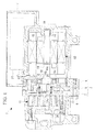
- FIG. 1 is a longitudinal cross-sectional view explaining, in outline, the configuration of the electric compressor according to this embodiment.
- This electric compressor 1 is a compressor employed in a vehicle air conditioner.
- a compressor-side housing 3 and an electric-motor-side housing 4 are securely fastened together with bolts 6, with a partition member 5 sandwiched therebetween, thus forming an aluminum-alloy housing 2 that forms an outer shell of the electric compressor 1.
- the partition member 5 is a member that separates the compressor-side housing 3 and the electric-motor-side housing 4 and is also a holding member for a main bearing 18, described later.
- an inverter box 7 is integrally formed at a top portion of the electric-motor-housing 4.
- a known scroll compression mechanism 11 is installed in the compressor-side housing 3, an electric motor 12 is installed in the electric- motor-side housing 4, and this scroll compression mechanism 11 and the electric motor 12 are integrated by being coaxially connected via a main shaft 14.
- a stator 15 and a rotor 16 that form the electric motor 12 are installed in the electric-motor-side housing 4; the stator 15 is secured to an inner circumferential surface of the electric-motor-side housing 4; and the rotor 16 is shrink-fitted to a rotor press-fitting portion 14a formed at an intermediate portion of the main shaft 14, which makes it integrally rotate together with the main shaft 14.
- the main shaft 14 is axially supported in a freely rotatable manner by the main bearing 18 held at the partition member 5 and a sub bearing 19 held at an end of the electric-motor-side housing 4.
- the main bearing 18 has a typical structure in which a plurality of ball bearings 18c are interposed between an outer race 18a and the inner race 18b.
- the sub bearing 19 is a typical needle bearing.
- the outer race 18a thereof is press-fitted to a bearing bore portion 5a formed in the partition member 5, and the inner race 18b thereof is press-fitted to a bearing journal portion 14b formed by increasing the diameter of the main shaft 14 by one level in the vicinity of the end thereof that is closer to the scroll compression mechanism 11.
- an outer diameter D1 of the main bearing 18 is smaller than an outer diameter D2 of the rotor 16 of the electric motor 12.
- a crank pin 14c is eccentrically provided on a front surface of the bearing journal portion 14b, and this crank pin 14c is linked to an orbiting scroll member 23, which is accommodated in a rear half of the compressor-side housing 3, in an eccentrically rotatable manner via a bush 21 and a bearing 22.
- the orbiting scroll member 23 is fitted to a stationary scroll member 24 that is accommodated in a front half of the compression-side housing 3 by being secured thereto.
- the bearing journal portion 14b formed on the main shaft 14 of the electric motor 12 is formed in a cylindrical shape without a level difference so that the inner race 18b of the main bearing 18 can be press-fitted from both sides in the axial direction thereof.
- Both shoulder portions of the bearing journal portion 14b are chamfered so as to facilitate press-fitting of the inner race 18b.
- an outer diameter d1 of the bearing journal portion 14b is set to be larger than an outer diameter d2 of the rotor press-fitting portion 14a.
- the bearing bore portion 5a formed in the partition member 5 is formed as a hole with a cylindrical shape, having a fixed inner diameter, without a level difference so that the outer race 18a of the main bearing 18 can be press-fitted from both sides in the axial direction thereof.
- Both shoulder portions of the bearing bore portion 5a are also chamfered so as to facilitate press-fitting of the outer race 18a.
- a space S into which a press-fitting tool T for press-fitting the main bearing 18 can be inserted is provided between the rotor press-fitting portion 14a of the main shaft 14 and the bearing journal portion 14b thereof.
- the main bearing 18 (inner race 18b) can be press-fitted to the bearing journal portion 14b of the main shaft 14 from both front and rear directions, and the degree of freedom for mounting when press-fitting the main bearing 18 can be enhanced.
- the bearing bore portion 5a in the partition member 5 in a shape with which the outer race 18a of the main bearing 18 can be press-fitted from both sides thereof in the axial direction, the main bearing 18 (outer race 18a) can be press-fitted to the bearing bore portion 5a from both front and rear directions, and with this point also, the degree of freedom for mounting when press-fitting the main bearing 18 can be enhanced.
- the degree of freedom for mounting related to press-fitting of the main bearing 18 can be considerably enhanced, and, as a result, even if the outer diameter D1 of the main bearing 18 is made smaller than the outer diameter D2 of the rotor 16, unlike in a conventional unit, the press-fitting directions for the partition member, 5 and the main bearing 18 are not restricted, and thus, the degree of freedom for designing the electric compressor 1 and the ease of performing the assembly thereof can be enhanced, which makes it possible to maintain good production efficiency.
- the rotor 16 can be shrink-fitted to the main shaft 14 at an early stage, handling of the main shaft 14 and the rotor 16 during the shrink-fitting step and after the shrink-fitting has been completed is improved, which eliminates concerns about them being dropped, hit, and so forth during assembling, causing various parts to be damaged or to form dents in the main bearing 18, thus deteriorating the durability thereof. Furthermore, pallets for transportation and storage after completing the shrink-fitting step can be made small, and a storage space can be made more compact.
- the space S into which the tool T for press-fitting the main bearing 18 can be inserted is provided between the rotor press-fitting portion 14a of the main shaft 14 and the bearing journal portion 14b thereof, even after the rotor 16 is press-fitted to the rotor press-fitting portion 14a, the main bearing 18 can be press-fitted to the bearing journal portion 14b, the partition member 5 can be press-fitted to an area surrounding the main bearing 18, which is press-fitted to the bearing journal portion 14b, and the partition member 5 to which the main bearing 18 is press-fitted in advance can be press-fitted to the bearing journal portion 14b, thus making it possible to further enhance the degree of freedom for mounting.
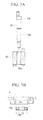
- Figs. 3A to 3D show a first embodiment of an assembly method when mounting the partition member 5, the main shaft 14, the rotor 16, and the main bearing 18.
- the rotor 16 is shrink-fitted to the rotor press-fitting portion 14a of the main shaft 14.
- the rotor 16 is heated, causing it to expand, whereas the main shaft 14 is cooled, causing it to shrink; the rotor press-fitting portion 14a of the main shaft 14 is inserted into a center hole 16a of the rotor 16; and both members 14 and 16 are subsequently cooled, thereby establishing the shrink-fitting.
- the outer race 18a of the main bearing 18 is press-fitted to the bearing bore portion 5a of the partition member 5 by using a press machine or the like so as to avoid tilting thereof.
- a push block of the press machine (not shown) is pressed by being brought into contact only with the outer race 18a, as indicated by arrows. If this pressing force is exerted on the inner race 18b, an axial load occurs between the outer race 18a and the inner race 18b, which is not desirable because this would cause dents therein.
- the other pressing block is pressed by being brought into contact with the vicinity of an area surrounding the bearing bore portion 5a of the partition member 5, as indicated by arrows.
- the position of the outer race 18a in the axial direction in the bearing bore portion 5a is set by employing a press-fitting positioning jig (not shown).
- the main bearing 18 in Fig. 3B is press-fitted to the bearing bore portion 5a of the partition member 5 from below, it may be press-fitted from above.
- either the shrink-fitting step shown in Fig. 3A or the outer-race press-fitting step shown in Fig. 3B may be performed first.
- the inner race 18b of the main bearing 18 attached to the partition member 5 is press-fitted to the bearing journal portion 14b of the main shaft 14 by means of a press machine or the like from an opposite side from the rotor 16 already attached to the main shaft 14.
- the front end of the main shaft 14 on the rotor 16 side is brought into contact with a push block P or the like of the press machine.
- the inner race 18b is press-fitted from the opposite side so that the pressing force for press-fitting is exerted only on the inner race 18b, as indicated by arrows.
- the position of the inner race 18b in the axial direction with respect to the bearing journal portion 14b is set by employing a press-fitting positioning jig (not shown).
- the movement of the main shaft 14 in the axial direction may be restricted by supporting the bearing journal portion 14b with the press-fitting tool T from the rotor 16 side.
- the position of the inner race 18b in the axial direction with respect to the bearing journal portion 14b is determined by the shape of the press-fitting tool T. Specifically, it is determined by the height of a protrusion formed at a tip of the press-fitting tool T that supports the bearing journal portion 14b.
- Figs. 4A to 4D show a second embodiment of the assembly method when mounting the partition member 5, the main shaft 14, the rotor 16, and the main bearing 18.
- This second embodiment assumes that the space S into which the press-fitting tool T can be inserted is provided between the rotor press-fitting portion 14a of the main shaft 14 and the bearing journal portion 14b thereof.
- the rotor 16 is shrink-fitted to the rotor press-fitting portion 14a of the main shaft 14.
- the specifics of the work involved are the same as those in the assembly method described in the first embodiment.
- the inner race 18b of the main bearing 18 is press-fitted to the bearing journal portion 14b of the main shaft 14 from the opposite side from the rotor 16.
- the bearing journal portion 14b is press-fitted to the inner race 18b from the rotor 16 side while inserting the press-fitting tool T into the space S, bringing it into contact with an end surface of the bearing journal portion 14b on the rotor 16 side; alternatively, the inner race 18b is press-fitted from the opposite side from the rotor 16 while restricting the movement of the main shaft 14 in the axial direction by bringing an end of the main shaft 14 on the rotor 16 side into contact with the pushing block P or the like of the press machine.
- the pressing force of the press machine is exerted only on the end surface of the inner race 18b, as shown by arrows.
- the position of the inner race 18b in the axial direction with respect to the bearing journal portion 14b is determined by, when the press-fitting tool T is employed, the shape of the press-fitting tool T, that is, the height of the protrusion formed at the tip of the press-fitting tool T, whereas, when the press-fitting tool T is not employed, it is set by employing the press-fitting positioning jig (not shown).
- the outer race 18a of the main bearing 18 is press-fitted to the bearing portion 5a of the partition member 5 by using the press machine or the like so as to avoid tilting thereof.
- the press-fitting tool T is brought into contact only with an end surface of the outer race 18a from the rotor 16 side.
- the push block of the press machine (not shown) is pressed by being brought into contact with vicinity of the area surrounding the bearing bore portion 5a of the partition member, 5, as indicated by arrows.
- the position of the outer race 18a in the axial direction in the bearing bore portion 5a is determined by the shape of the press-fitting tool T.
- Fig. 5 is a longitudinal cross-sectional view showing a first modification of the present invention.
- Figs. 6 and 7 portions that are the same as those in the embodiment shown in Fig. 3D are given the same reference signs, and descriptions thereof will be omitted.
- a positioning flange 5b is formed in the bearing bore 5a of the partition member 5. This positioning flange 5b protrudes along the circumferential direction at an inner circumference of an end of the bearing bore 5a on the opposite side from the rotor 16.
- this positioning flange 5b is formed, it suffices to press-fit the outer race 18a until it comes into contact with the positioning flange 5b when press-fitting the outer race 18a of the main bearing 18 to the bearing bore 5a; therefore, positioning thereof can be performed accurately.
- Fig. 6 is a longitudinal cross-sectional view showing a second modification of the present invention.
- a positioning flange 14d is formed in the bearing journal portion 14b of the main shaft 14. This positioning flange 14d protrudes at an outer circumference of an end of the bearing journal portion 14b on the rotor 16 side, in the circumferential direction.
- this positioning flange 14d is formed, it suffices to press-fit the inner race 18b until it comes into contact with the positioning flange 14c when press-fitting the inner race 18b of the main bearing 18 to the bearing journal portion 14b; therefore, positioning thereof can be performer accurately.
- Fig. 7 is a longitudinal cross-sectional view showing a third modification of the present invention.
- the positioning flange 5b is formed in the bearing bore 5a of the partition member 5, and the positioning flange 14d is formed in the bearing journal portion 14b of the main shaft 14.
- the positioning flange 5b protrudes at the inner circumference of the end of the bearing bore 5a on the opposite side from the rotor 16, and the positioning flange 14d protrudes at the outer circumference of the end of the bearing journal portion 14b on the rotor 16 side.
- the press-fitting position of the main bearing 18 with respect to the bearing bore 5a and the bearing journal portion 14b can be set accurately.
Landscapes
- Engineering & Computer Science (AREA)
- Mechanical Engineering (AREA)
- General Engineering & Computer Science (AREA)
- Power Engineering (AREA)
- Manufacturing & Machinery (AREA)
- Compressor (AREA)
- Applications Or Details Of Rotary Compressors (AREA)
- Connection Of Motors, Electrical Generators, Mechanical Devices, And The Like (AREA)
- Manufacture Of Motors, Generators (AREA)
- Mounting Of Bearings Or Others (AREA)
Abstract
Description
- The present invention relates to an electric compressor in which an electric motor and a compressor are coaxially integrated in a housing and which is suitable for use in a vehicle air conditioner in particular, and to an assembly method thereof.
- In recent years, there has been a rapid advance in the development and market introduction of vehicles other than automobiles that travel by means of internal combustion engines, such as electric automobiles and hybrid automobiles, or ones that travel by means of motive power from electric motors, like fuel-cell automobiles. In many air conditioners for such automobiles whose motive power is provided by electric motors, with regard to compressors that compress and feed refrigerant, electric compressors whose motive power is derived from the electric motors serving as a driving source are also employed.
- In addition, air conditioners for automobiles that travel by means of motive power from internal combustion engines also include those that employ electric compressors instead of compressors driven, via electromagnetic clutches, by the internal combustion engines used for traveling in order to alleviate the deterioration in drivability associated with contact breakages in the electromagnetic clutches.
- As such electric compressors, sealed electric compressors in which electric motors and compressors are built into and coaxially integrated in a single housing have been employed, as disclosed in
Fig. 1 ofPatent Literature 1. As with many other electric compressors, the electric compressor disclosed inPatent Literature 1 is formed by joining a compressor-side housing, which accommodates a compressor, and an electric-motor-side housing, which accommodates an electric motor, and a partition member is disposed therebetween so as to separate them. - Then, a rear end and the vicinity of a front end of a main shaft of the electric motor are supported with a large-diameter main bearing that is press-fitted to the partition member and a small-diameter sub bearing provided at a back portion of the electric-motor-side housing. A rotor that forms the electric motor is provided at an intermediate portion of this main shaft so as to rotate integrally together therewith. The rotor is generally shrink-fitted to the main shaft. In addition, the front end of the main shaft into the compressor-side housing and is connected thereto to drive a rotational compression member that forms the compressor.
- With the electric compressor of
Patent Literature 1, the main-bearing outer diameter is made smaller than the rotor outer diameter. By making the main-bearing diameter smaller than that of the rotor in this way, a structure around a connecting portion between the main shaft and the rotational compression member of the compressor can be made more compact, the weight thereof can be reduced, and the assembly thereof can be simplified. - As for the main bearing, an outer race (outer wheel member) thereof is press-fitted to the bearing bore portion formed in the partition member from the electric-motor side, and the outer race is brought into contact with a positioning flange formed at an inner circumference of the bearing bore portion at the end thereof on the compressor side, thus setting the position thereof. In addition, a bearing journal portion formed in the main shaft is press-fitted to an inner race (inner wheel member) of the main bearing from the compressor side, and the inner race is brought into contact with a positioning flange formed at an outer circumference of the bearing journal portion at the end thereof on the compressor side, thus setting the position thereof. Here, expressions "press-fitted from the electric-motor side" and "press-fitted from the compressor side" indicate from which side of the partition member or the main bearing the press-fitting is performed; it does not indicate that the press-fitting is performed inside the housing of the electric compressor, and the individual press-fitting procedures are actually performed in a state in which the partition member, the main bearing, and the main shaft are outside the housing of the electric compressor.
- In this electric compressor of
Patent Literature 1, the assembly order of the main shaft, the rotor, the main bearing, and the partition member is presumed to be as follows. Specifically, the assembly order is such that, first, the outer race of the main bearing is press-fitted to the bearing bore portion of the partition member from the electric-motor side; next, the bearing journal portion of the main shaft is press-fitted to the inner race of the main bearing from the compressor side; next, the rotor is inserted into a rotor press-fitting portion formed at the intermediate portion of the main shaft from the electric-motor side and is shrink-fitted thereto; and, finally, the rotor is cooled, which establishes the shrink-fitting. -
-
PTL 1 Japanese Unexamined Patent Application, Publication No.2008-099365 - However, with the assembly order described above, because the main shaft, the main bearing, and the partition member are integrated in stages before the rotor shrink-fitting step, making the workpiece shape to be handled large, during the rotor shrink-fitting step and during transport to the next step, as well as during storage in a state in which the shrink-fitting has been completed, pallets used for transportation and storage must be made large, and a considerable storage space is also necessary.
- In addition to the workpiece shape becoming large in the shrink-fitting step in this way, because the partition member freely rotates with respect to the main shaft via the main bearing, it is difficult to hold the workpiece, and it may be dropped, hit, and so forth during handling, causing various parts to be damaged or to form dents in the main bearing, which deteriorates the durability thereof.
- In order to enhance the ease of performing the task by reducing the size of the workpiece shape during the rotor shrink-ftting step and after the shrink-fitting step, it is desirable to make the assembly order such that the rotor is shrink-fitted to the main shaft first, and the inner race of the main bearing is subsequently press-fitted to the main shaft. However, if the rotor and the main bearing are mounted to the main shaft first, problems such as the following occur when subsequently press-fitting the outer race of the main bearing to the partition member.
- Specifically, because the outer race is press-fitted to the partition member by being pressed from the electric-motor side, the outer race needs to be pressed with a press-fitting tool; however, because the rotor outer diameter is larger than the main-bearing outer diameter, the rotor protrudes so as to overlap with the outer race, and the rotor interferes, making it impossible to insert the press-fitting tool between the outer race and the rotor. However, if the rear end of the main shaft is pressed to press-fit the outer race to the partition member, an axial load (a shearing load in the axial direction) is exerted between the inner race and the outer race of the main bearing, which causes dents, and, moreover, the inner race that has already been press-fitted may be shifted with respect to the main shaft, which is not desirable.
- In addition, even if the outer race of the main bearing is press-fitted to the partition member first, and the bearing journal portion of the main shaft is subsequently press-fitted to the inner race from the electric-motor side, because the positioning flange is formed at the outer circumference of the end of the bearing journal portion on the compressor side, as described above, press-fitting thereof is impossible. In this way, with the electric compressor in which the main-bearing outer diameter is smaller than the rotor outer diameter, there are many restrictions in the press-fitting order of the main shaft, the main bearing, the partition member, and the rotor, which makes the production efficiency low.
- The present invention has been conceived in light of the above-described circumstances, and an object thereof is to provide an electric compressor in which a main-bearing outer diameter can be made smaller than a rotor outer diameter in an electric motor without causing a drop in the production efficiency thereof and which also makes it possible to mount the rotor to a main shaft in an early stage, thus improving the ease of performing a shrink-fitting step, as well as to provide an assembly method thereof. Solution to Problem
- In order to solve the above-described problems, the present invention employs the following solutions.
Specifically, an electric compressor according to a first aspect of the present invention is an electric compressor in which an electric motor and a compressor are coaxially integrated in a housing; a rotor is shrink-fitted to a rotor press-fitting portion formed at an intermediate portion of a main shaft of the electric motor; an inner race of a main bearing is press-fitted to a bearing journal portion formed near an end of the main shaft on a compressor side; and an outer race of the main bearing is press-fitted to a bearing bore portion formed in a partition member that separates the electric motor and the compressor, wherein the bearing journal portion is formed in a shape into which the inner race can be press-fitted from both sides in an axial direction thereof, and, in addition, an outer diameter of the bearing journal portion is made larger than an outer diameter of the rotor press-fitting portion, whereas the bearing bore portion is formed in a shape into which the outer race can be press-fitted from both sides in an axial direction thereof. - With the electric compressor according to the first aspect of the present invention described above, the inner race and the outer race of the main bearing can be press-fitted to the bearing journal portion of the main shaft and the bearing bore portion of the partition member, respectively, from both sides in the axial direction thereof, which enhances the degree of freedom for mounting when press-fitting the main bearing. Accordingly, the rotor, with a larger diameter than the main bearing, can be shrink-fitted to the main shaft at an early stage, which enhances the ease of performing the shrink-fitting step. Therefore, even if the main-bearing outer diameter is made smaller than the rotor outer diameter, production efficiency does not drop.
- It is desirable that an electric compressor according to a second aspect of the present invention be configured such that, in the first aspect described above, a space into which a tool for press-fitting the main bearing can be inserted is provided between the rotor press-fitting portion and the bearing journal portion of the main shaft.
With this configuration, even after the rotor is press-fitted to the rotor press-fitting portion, the main bearing can be press-fitted to the bearing journal portion, the partition member can be press-fitted to an area surrounding the main bearing, which is press-fitted to the bearing journal portion, and the partition member to which the main bearing is press-fitted in advance can be press-fitted to the bearing journal portion, which further enhances the degree of freedom for mounting. - An assembly method of an electric compressor according to the first aspect of the present invention is an assembly method for an electric compressor including, in a step of assembling an electric compressor according to the above-described first aspect, first, shrink-fitting the rotor to the rotor press-fitting portion of the main shaft; also press-fitting the outer race of the main bearing to the bearing bore portion of the partition member; and subsequently press-fitting the inner race of the main bearing to the bearing journal portion of the main shaft from an opposite side from the rotor.
- With this assembly method, because the rotor of the electric motor is shrink-fitted to the main shaft at an early stage, the ease of performing the shrink-fitting step is enhanced. In addition, even if the main-bearing outer diameter is made smaller than the rotor outer diameter, the main bearing can be easily press-fitted to the main shaft and the partition member, and thus, production efficiency does not drop. Furthermore, because the main shaft and the partition member are combined after the work involved in mounting the rotor to the main shaft and the work involved in press-fitting the main bearing to the partition member are separately performed, the work efficiency is high.
- An assembly method of an electric compressor according to the second aspect of the present invention is an assembly method for an electric compressor including, in a step of assembling an electric compressor according to the above-described second aspect, first, shrink-fitting the rotor to the rotor press-fitting portion of the main shaft; next, press-fitting the bearing journal portion to the inner race of the main bearing from a rotor side while bringing the press-fitting tool into contact with an end surface of the bearing journal portion on the rotor side; and subsequently press-fitting the outer race to the bearing bore portion of the partition member from the rotor side while bringing the press-fitting tool into contact with the end surface of the outer race on the rotor side.
- With this assembly method, because the rotor of the electric motor is shrink-fitted to the main shaft at an early stage, the ease of performing the shrink-fitting step is enhanced. In addition, in the case in which the main-bearing outer diameter is made smaller than the rotor outer diameter, the main bearing can be easily press-fitted to the main shaft or the partition member by employing the press-fitting tool even after shrink-fitting the rotor to the main shaft.
- With an electric compressor and an assembly method thereof according to the present invention, a main-bearing outer diameter can be made smaller than a rotor outer diameter without causing a drop in production efficiency, and, in addition, the ease of performing a shrink-fitting step can be enhanced by making it possible to mount a rotor of an electric motor to a main shaft at an early stage.
-
-
Fig. 1 is a longitudinal cross-sectional view explaining, in outline, the configuration of an electric compressor according to an embodiment of the present invention. -
Fig. 2 is a longitudinal cross-sectional view in which the vicinities of a partition member and a main bearing of the electric compressor shown inFig. 1 are enlarged. -
Fig. 3A is a longitudinal cross-sectional view showing a shrink-fitting step in a first embodiment of an assembly method of the electric compressor according to the present invention. -
Fig. 3B is a longitudinal cross-sectional view showing an outer-race press-fitting step in the first embodiment of the assembly method of the electric compressor according to the present invention. -
Fig. 3C is a longitudinal cross-sectional view showing an inner-race press-fitting step in the first embodiment of the assembly method of the electric compressor according to the present invention. -
Fig. 3D is a longitudinal cross-sectional view showing a state in which the assembly has been completed in the first embodiment of the assembly method of the electric compressor according to the present invention. -
Fig. 4A is a longitudinal cross-sectional view showing a shrink-fitting step in a second embodiment of an assembly method of the electric compressor according to the present invention. -
Fig. 4B is a longitudinal cross-sectional view showing an inner-race press-fitting step in the second embodiment of the assembly method of the electric compressor according to the present invention. -
Fig. 4C is a longitudinal cross-sectional view showing an outer-race press-fitting step in the second embodiment of the assembly method of the electric compressor according to the present invention. -
Fig. 4D is a longitudinal cross-sectional view showing a state in which the assembly has been completed in the second embodiment of the assembly method of the electric compressor according to the present invention. -
Fig. 5 is a longitudinal cross-sectional view showing a first modification of the present invention. -
Fig. 6 is a longitudinal cross-sectional view showing a second modification of the present invention. -
Fig. 7 is a longitudinal cross-sectional view showing a third modification of the present invention. - Embodiments of an electric compressor and an assembly method thereof according to the present invention will be described below with reference to
Figs. 1 and2 .Fig. 1 is a longitudinal cross-sectional view explaining, in outline, the configuration of the electric compressor according to this embodiment. Thiselectric compressor 1 is a compressor employed in a vehicle air conditioner. - A compressor-
side housing 3 and an electric-motor-side housing 4 are securely fastened together with bolts 6, with apartition member 5 sandwiched therebetween, thus forming an aluminum-alloy housing 2 that forms an outer shell of theelectric compressor 1. Thepartition member 5 is a member that separates the compressor-side housing 3 and the electric-motor-side housing 4 and is also a holding member for amain bearing 18, described later. Note that an inverter box 7 is integrally formed at a top portion of the electric-motor-housing 4. - A known
scroll compression mechanism 11 is installed in the compressor-side housing 3, anelectric motor 12 is installed in the electric- motor-side housing 4, and thisscroll compression mechanism 11 and theelectric motor 12 are integrated by being coaxially connected via amain shaft 14. Astator 15 and arotor 16 that form theelectric motor 12 are installed in the electric-motor-side housing 4; thestator 15 is secured to an inner circumferential surface of the electric-motor-side housing 4; and therotor 16 is shrink-fitted to a rotor press-fittingportion 14a formed at an intermediate portion of themain shaft 14, which makes it integrally rotate together with themain shaft 14. - The
main shaft 14 is axially supported in a freely rotatable manner by themain bearing 18 held at thepartition member 5 and asub bearing 19 held at an end of the electric-motor-side housing 4. As shown inFig. 2 , themain bearing 18 has a typical structure in which a plurality of ball bearings 18c are interposed between anouter race 18a and theinner race 18b. In addition, thesub bearing 19 is a typical needle bearing. - With regard to the main beating 18, the
outer race 18a thereof is press-fitted to abearing bore portion 5a formed in thepartition member 5, and theinner race 18b thereof is press-fitted to abearing journal portion 14b formed by increasing the diameter of themain shaft 14 by one level in the vicinity of the end thereof that is closer to thescroll compression mechanism 11. As shown inFig. 2 , an outer diameter D1 of themain bearing 18 is smaller than an outer diameter D2 of therotor 16 of theelectric motor 12. - A
crank pin 14c is eccentrically provided on a front surface of thebearing journal portion 14b, and this crankpin 14c is linked to anorbiting scroll member 23, which is accommodated in a rear half of the compressor-side housing 3, in an eccentrically rotatable manner via abush 21 and abearing 22. Theorbiting scroll member 23 is fitted to astationary scroll member 24 that is accommodated in a front half of the compression-side housing 3 by being secured thereto. - When the
electric motor 12 is activated and themain shaft 14 is rotated, this rotation causes theorbiting scroll member 23 to eccentrically rotate via thecrank pin 14c, thebush 21, and thebearing 22, and, by doing so, air suction, compression, and air exhaust effects are continuously generated between the orbitingscroll member 23 and thestationary scroll member 24. Accordingly, low-pressure refrigerant gas is taken in from a refrigerant inlet (not shown) provided at an end of the electric-motor-side housing 4, and this refrigerant gas is taken into thescroll compression mechanism 11 after flowing through the electric-motor-side housing 4, thus cooling theelectric motor 12, is compressed therein to reach a high temperature and high pressure, and is expelled from an outlet (not shown) provided at an end of the compressor-side housing 3. Note that theelectric motor 12 is controlled by aninverter device 27 accommodated inside the inverter box 7, and operating heat generated at theinverter device 27 is cooled by the refrigerant gas that flows in the electric-motor-side housing 4. - As shown in
Fig. 2 in an enlarged view, thebearing journal portion 14b formed on themain shaft 14 of theelectric motor 12 is formed in a cylindrical shape without a level difference so that theinner race 18b of themain bearing 18 can be press-fitted from both sides in the axial direction thereof. Both shoulder portions of thebearing journal portion 14b are chamfered so as to facilitate press-fitting of theinner race 18b. In addition, an outer diameter d1 of thebearing journal portion 14b is set to be larger than an outer diameter d2 of the rotor press-fittingportion 14a. - On the other hand, the bearing bore
portion 5a formed in thepartition member 5 is formed as a hole with a cylindrical shape, having a fixed inner diameter, without a level difference so that theouter race 18a of themain bearing 18 can be press-fitted from both sides in the axial direction thereof. Both shoulder portions of the bearing boreportion 5a are also chamfered so as to facilitate press-fitting of theouter race 18a. - Furthermore, a space S into which a press-fitting tool T for press-fitting the
main bearing 18 can be inserted, shown inFig. 3C , as well asFigs. 4B and4C , is provided between the rotor press-fittingportion 14a of themain shaft 14 and thebearing journal portion 14b thereof. - With the
electric compressor 1 configured as described above, by forming thebearing journal portion 14b of themain shaft 14 in a shape with which theinner race 18b of themain bearing 18 can be press-fitted from both sides thereof in the axial direction and by making the outer diameter d1 of thisbearing journal portion 14b larger than the outer diameter d2 of the rotor press-fittingportion 14a, the main bearing 18 (inner race 18b) can be press-fitted to thebearing journal portion 14b of themain shaft 14 from both front and rear directions, and the degree of freedom for mounting when press-fitting themain bearing 18 can be enhanced. - In addition, by forming the bearing bore
portion 5a in thepartition member 5 in a shape with which theouter race 18a of themain bearing 18 can be press-fitted from both sides thereof in the axial direction, the main bearing 18 (outer race 18a) can be press-fitted to the bearing boreportion 5a from both front and rear directions, and with this point also, the degree of freedom for mounting when press-fitting themain bearing 18 can be enhanced. - With these features, the degree of freedom for mounting related to press-fitting of the
main bearing 18 can be considerably enhanced, and, as a result, even if the outer diameter D1 of themain bearing 18 is made smaller than the outer diameter D2 of therotor 16, unlike in a conventional unit, the press-fitting directions for the partition member, 5 and themain bearing 18 are not restricted, and thus, the degree of freedom for designing theelectric compressor 1 and the ease of performing the assembly thereof can be enhanced, which makes it possible to maintain good production efficiency. - Moreover, because the
rotor 16 can be shrink-fitted to themain shaft 14 at an early stage, handling of themain shaft 14 and therotor 16 during the shrink-fitting step and after the shrink-fitting has been completed is improved, which eliminates concerns about them being dropped, hit, and so forth during assembling, causing various parts to be damaged or to form dents in themain bearing 18, thus deteriorating the durability thereof. Furthermore, pallets for transportation and storage after completing the shrink-fitting step can be made small, and a storage space can be made more compact. - Note that, because positioning flanges for the
main bearing 18 are not formed at thebearing journal portion 14b of themain shaft 14 and the bearing boreportion 5a of thepartition member 5, in the unlikely event of foreign objects becoming attached to the outer circumferential surface of thebearing journal portion 14b, the inner circumferential surface of the bearing boreportion 5a, or the end surface of themain bearing 18, the foreign objects will not become caught between the positioning flanges and themain bearing 18. Accordingly, position shifting or tilting of themain bearing 18 due to the foreign objects can be prevented, and a drop in production efficiency can be avoided. - In addition, because the space S into which the tool T for press-fitting the
main bearing 18 can be inserted is provided between the rotor press-fittingportion 14a of themain shaft 14 and thebearing journal portion 14b thereof, even after therotor 16 is press-fitted to the rotor press-fittingportion 14a, themain bearing 18 can be press-fitted to thebearing journal portion 14b, thepartition member 5 can be press-fitted to an area surrounding themain bearing 18, which is press-fitted to thebearing journal portion 14b, and thepartition member 5 to which themain bearing 18 is press-fitted in advance can be press-fitted to thebearing journal portion 14b, thus making it possible to further enhance the degree of freedom for mounting. -
Figs. 3A to 3D show a first embodiment of an assembly method when mounting thepartition member 5, themain shaft 14, therotor 16, and themain bearing 18. - First, in the shrink-fitting step shown in
Fig. 3A , therotor 16 is shrink-fitted to the rotor press-fittingportion 14a of themain shaft 14. In this shrink-fitting step, therotor 16 is heated, causing it to expand, whereas themain shaft 14 is cooled, causing it to shrink; the rotor press-fittingportion 14a of themain shaft 14 is inserted into acenter hole 16a of therotor 16; and bothmembers - In an outer-race press-fitting step shown in
Fig. 3B , on the other hand, theouter race 18a of themain bearing 18 is press-fitted to the bearing boreportion 5a of thepartition member 5 by using a press machine or the like so as to avoid tilting thereof. In this outer-race press-fitting step, a push block of the press machine (not shown) is pressed by being brought into contact only with theouter race 18a, as indicated by arrows. If this pressing force is exerted on theinner race 18b, an axial load occurs between theouter race 18a and theinner race 18b, which is not desirable because this would cause dents therein. In addition, the other pressing block is pressed by being brought into contact with the vicinity of an area surrounding the bearing boreportion 5a of thepartition member 5, as indicated by arrows. - Note that the position of the
outer race 18a in the axial direction in the bearing boreportion 5a is set by employing a press-fitting positioning jig (not shown). In addition, although themain bearing 18 inFig. 3B is press-fitted to the bearing boreportion 5a of thepartition member 5 from below, it may be press-fitted from above. Furthermore, either the shrink-fitting step shown inFig. 3A or the outer-race press-fitting step shown inFig. 3B may be performed first. - Next, in an inner-race press-fitting step shown in
Fig. 3C , theinner race 18b of themain bearing 18 attached to thepartition member 5 is press-fitted to thebearing journal portion 14b of themain shaft 14 by means of a press machine or the like from an opposite side from therotor 16 already attached to themain shaft 14. At this time, in order to restrict movement of themain shaft 14 in the axial direction, the front end of themain shaft 14 on therotor 16 side is brought into contact with a push block P or the like of the press machine. Then, theinner race 18b is press-fitted from the opposite side so that the pressing force for press-fitting is exerted only on theinner race 18b, as indicated by arrows. The position of theinner race 18b in the axial direction with respect to thebearing journal portion 14b is set by employing a press-fitting positioning jig (not shown). - Note that, in the case in which the space S into which the press-fitting tool T can be inserted is provided between the rotor press-fitting
portion 14a of themain shaft 14 and thebearing journal portion 14b thereof, the movement of themain shaft 14 in the axial direction may be restricted by supporting thebearing journal portion 14b with the press-fitting tool T from therotor 16 side. At this time, the position of theinner race 18b in the axial direction with respect to thebearing journal portion 14b is determined by the shape of the press-fitting tool T. Specifically, it is determined by the height of a protrusion formed at a tip of the press-fitting tool T that supports thebearing journal portion 14b. - As shown in
Fig. 3D , assembly of thepartition member 5, themain shaft 14, therotor 16, and themain bearing 18 is completed in this way. With this assembly method, because therotor 16 is shrink-fitted to themain shaft 14 in the earliest stage, the ease of performing the shrink-fitting step can be enhanced. In addition, even if the outer diameter of themain bearing 18 is made smaller than the outer diameter of therotor 16, themain bearing 18 can be easily press-fitted to themain shaft 14 and thepartition member 5, and the production efficiency does not drop. Furthermore, because themain shaft 14 and thepartition member 5 are combined after the work involved in mounting therotor 16 to themain shaft 14 and the work involved in press-fitting themain bearing 18 to thepartition member 5 are separately performed, the work efficiency can be increased. -
Figs. 4A to 4D show a second embodiment of the assembly method when mounting thepartition member 5, themain shaft 14, therotor 16, and themain bearing 18. This second embodiment assumes that the space S into which the press-fitting tool T can be inserted is provided between the rotor press-fittingportion 14a of themain shaft 14 and thebearing journal portion 14b thereof. - First, in a shrink-fitting step shown in
Fig. 4A , therotor 16 is shrink-fitted to the rotor press-fittingportion 14a of themain shaft 14. The specifics of the work involved are the same as those in the assembly method described in the first embodiment. - Next, in an inner-race press-fitting step shown in
Fig. 4B , theinner race 18b of themain bearing 18 is press-fitted to thebearing journal portion 14b of themain shaft 14 from the opposite side from therotor 16. At this time, thebearing journal portion 14b is press-fitted to theinner race 18b from therotor 16 side while inserting the press-fitting tool T into the space S, bringing it into contact with an end surface of thebearing journal portion 14b on therotor 16 side; alternatively, theinner race 18b is press-fitted from the opposite side from therotor 16 while restricting the movement of themain shaft 14 in the axial direction by bringing an end of themain shaft 14 on therotor 16 side into contact with the pushing block P or the like of the press machine. At this time, the pressing force of the press machine is exerted only on the end surface of theinner race 18b, as shown by arrows. Note that the position of theinner race 18b in the axial direction with respect to thebearing journal portion 14b is determined by, when the press-fitting tool T is employed, the shape of the press-fitting tool T, that is, the height of the protrusion formed at the tip of the press-fitting tool T, whereas, when the press-fitting tool T is not employed, it is set by employing the press-fitting positioning jig (not shown). - Next, in an outer-race press-fitting step shown in
Fig. 4C , theouter race 18a of themain bearing 18 is press-fitted to the bearingportion 5a of thepartition member 5 by using the press machine or the like so as to avoid tilting thereof. At this time, the press-fitting tool T is brought into contact only with an end surface of theouter race 18a from therotor 16 side. On the other hand, the push block of the press machine (not shown) is pressed by being brought into contact with vicinity of the area surrounding the bearing boreportion 5a of the partition member, 5, as indicated by arrows. The position of theouter race 18a in the axial direction in the bearing boreportion 5a is determined by the shape of the press-fitting tool T. - As shown in
Fig. 4D , assembly of thepartition 5, themain shaft 14, therotor 16, and themain bearing 18 is completed in this way. With this assembly method, because therotor 16 is shrink-fitted to themain shaft 14 in the earliest stage, as with the assembly method of the first embodiment, the ease of performing during the shrink-fitting step can be enhanced. In addition, in the case in which the outer diameter of themain bearing 18 is made smaller than the outer diameter of therotor 16, themain bearing 18 can be easily and reliably press-fitted to thebearing journal portion 14b or the bearing boreportion 5a by employing the press-fitting tool T, even after therotor 16 has been shrink-fitted to themain shaft 14. -
Fig. 5 is a longitudinal cross-sectional view showing a first modification of the present invention. In this figure, as well asFigs. 6 and7 , described later, portions that are the same as those in the embodiment shown inFig. 3D are given the same reference signs, and descriptions thereof will be omitted. - In this first modification, a
positioning flange 5b is formed in the bearing bore 5a of thepartition member 5. Thispositioning flange 5b protrudes along the circumferential direction at an inner circumference of an end of the bearing bore 5a on the opposite side from therotor 16. - Because this
positioning flange 5b is formed, it suffices to press-fit theouter race 18a until it comes into contact with thepositioning flange 5b when press-fitting theouter race 18a of themain bearing 18 to the bearing bore 5a; therefore, positioning thereof can be performed accurately. -
Fig. 6 is a longitudinal cross-sectional view showing a second modification of the present invention. In this second modification, apositioning flange 14d is formed in thebearing journal portion 14b of themain shaft 14. Thispositioning flange 14d protrudes at an outer circumference of an end of thebearing journal portion 14b on therotor 16 side, in the circumferential direction. - Because this
positioning flange 14d is formed, it suffices to press-fit theinner race 18b until it comes into contact with thepositioning flange 14c when press-fitting theinner race 18b of themain bearing 18 to thebearing journal portion 14b; therefore, positioning thereof can be performer accurately. -
Fig. 7 is a longitudinal cross-sectional view showing a third modification of the present invention, In this third modification, thepositioning flange 5b is formed in the bearing bore 5a of thepartition member 5, and thepositioning flange 14d is formed in thebearing journal portion 14b of themain shaft 14. Thepositioning flange 5b protrudes at the inner circumference of the end of the bearing bore 5a on the opposite side from therotor 16, and thepositioning flange 14d protrudes at the outer circumference of the end of thebearing journal portion 14b on therotor 16 side. - By forming the
positioning flange 5b in the bearing bore 5a and also by forming thepositioning flange 14d in thebearing journal portion 14b in this way, the press-fitting position of themain bearing 18 with respect to the bearing bore 5a and thebearing journal portion 14b can be set accurately. - Note that, even if the first to third modifications described above are employed, the first embodiment and the second embodiment of the assembly method according to the present invention can both be applied.
-
- 1 electric compressor
- 2 housing
- 3 compressor-side housing
- 4 electric-motor-side housing
- 5 partition member
- 5a bearing bore portion
- 11 scroll compression mechanism, serving as a compressor
- 12 electric motor
- 14 main shaft
- 14a rotor press-fitting portion
- 14b bearing journal portion
- 16 rotor
- 18 main bearing
- 18a outer race
- 18b inner race
- D1 main-bearing outer diameter
- D2 rotor outer diameter
- S space
- T press-fitting tool
Claims (4)
- An electric compressor in which an electric motor and a compressor are coaxially integrated in a housing; a rotor is shrink-fitted to a rotor press-fitting portion formed at an intermediate portion of a main shaft of the electric motor; an inner race of a main bearing is press-fitted to a bearing journal portion formed near an end of the main shaft on a side of the compressor; and an outer race of the main bearing is press-fitted to a bearing bore portion formed in a partition member that separates the electric motor and the compressor, wherein
the bearing journal portion is formed in a shape into which the inner race can be press-fitted from both sides in an axial direction thereof, and, in addition, an outer diameter of the bearing journal portion is made larger than an outer diameter of the rotor press-fitting portion,
whereas the bearing bore portion is formed in a shape into which the outer race can be press-fitted from both sides in an axial direction thereof. - An electric compressor according to Claim 1, wherein a space into which a press-fitting tool for press-fitting the main bearing can be inserted is provided between the rotor press-fitting portion and the bearing journal portion of the main shaft.
- An assembly method for an electric compressor comprising, in a step of assembling an electric compressor according to Claim 1:first, shrink-fitting the rotor to the rotor press-fitting portion of the main shaft;also press-fitting the outer race of the main bearing to the bearing bore portion of the partition member; andsubsequently press-fitting the inner race of the main bearing to the bearing journal portion of the main shaft from an opposite side from the rotor.
- An assembly method for an electric compressor comprising, in a step of assembling an electric compressor according to Claim 2:first, shrink-fitting the rotor to the rotor press-fitting portion of the main shaft;next, press-fitting the bearing journal portion to the inner race of the main bearing from a rotor side while bringing the press-fitting tool into contact with an end surface of the bearing journal portion on the rotor side; andsubsequently press-fitting the outer race to the bearing bore portion of the partition member from the rotor side while bringing the press-fitting tool into contact with the end surface of the outer race on the rotor side.
Applications Claiming Priority (2)
| Application Number | Priority Date | Filing Date | Title |
|---|---|---|---|
| JP2010041086A JP5455707B2 (en) | 2010-02-25 | 2010-02-25 | Electric compressor and method for assembling the same |
| PCT/JP2010/064490 WO2011104910A1 (en) | 2010-02-25 | 2010-08-26 | Electric compressor, and method for assembling same |
Publications (3)
| Publication Number | Publication Date |
|---|---|
| EP2541063A1 true EP2541063A1 (en) | 2013-01-02 |
| EP2541063A4 EP2541063A4 (en) | 2017-09-06 |
| EP2541063B1 EP2541063B1 (en) | 2019-11-13 |
Family
ID=44506349
Family Applications (1)
| Application Number | Title | Priority Date | Filing Date |
|---|---|---|---|
| EP10846573.3A Active EP2541063B1 (en) | 2010-02-25 | 2010-08-26 | Method for assembling an electric compressor |
Country Status (4)
| Country | Link |
|---|---|
| US (1) | US9109589B2 (en) |
| EP (1) | EP2541063B1 (en) |
| JP (1) | JP5455707B2 (en) |
| WO (1) | WO2011104910A1 (en) |
Families Citing this family (10)
| Publication number | Priority date | Publication date | Assignee | Title |
|---|---|---|---|---|
| JP2013212009A (en) * | 2012-03-30 | 2013-10-10 | Kayaba Ind Co Ltd | Motor shaft |
| CN103051115B (en) * | 2012-12-31 | 2014-12-31 | 广东超力微电机有限公司 | Assembling machine for micromotor stator assemblies |
| JP6257163B2 (en) * | 2013-03-22 | 2018-01-10 | 株式会社ミツバ | Rotating shaft and motor with speed reduction mechanism using the same |
| JP6148507B2 (en) * | 2013-03-22 | 2017-06-14 | 株式会社ミツバ | Rotating shaft and motor with speed reduction mechanism using the same |
| DE102016204756B4 (en) * | 2015-12-23 | 2024-01-11 | OET GmbH | Electric refrigerant drive |
| DE102016118743B4 (en) | 2016-10-04 | 2020-01-02 | Rheinmetall Landsysteme Gmbh | Ground starting device for starting and maintaining jet engines of aircraft and other aircraft |
| DE102016125400A1 (en) * | 2016-12-22 | 2018-06-28 | OET GmbH | Method for producing a scroll compressor |
| KR102002124B1 (en) * | 2018-02-26 | 2019-07-19 | 엘지전자 주식회사 | Motor operated compressor |
| DE102018204278B4 (en) * | 2018-03-20 | 2020-02-06 | Volkswagen Aktiengesellschaft | Spiral compressor and method for its assembly |
| DE102022111377A1 (en) * | 2022-05-06 | 2023-11-09 | OET GmbH | Displacement machine based on the spiral principle |
Family Cites Families (14)
| Publication number | Priority date | Publication date | Assignee | Title |
|---|---|---|---|---|
| US4181474A (en) * | 1978-03-02 | 1980-01-01 | Dunham-Bush, Inc. | Vertical axis hermetic rotary helical screw compressor with improved rotary bearings and oil management |
| US4340830A (en) | 1979-11-30 | 1982-07-20 | Scm Corporation | Electric motor assembly |
| JPS58192455A (en) | 1982-04-30 | 1983-11-09 | Matsushita Electric Works Ltd | Gap adjusting method for axial gap motor |
| JPH0620687B2 (en) * | 1987-11-09 | 1994-03-23 | 株式会社日立製作所 | Bearing press-fitting method and bearing press-fitting device |
| JPH05328686A (en) | 1992-05-15 | 1993-12-10 | Sony Corp | Inner rotor type motor |
| US5272803A (en) | 1993-02-05 | 1993-12-28 | Synektron Corporation | Method and apparatus for electric motor assembly with bearing preload |
| JP2002339883A (en) | 2001-05-16 | 2002-11-27 | Nippon Soken Inc | Scroll compressor |
| JP4040300B2 (en) | 2001-12-28 | 2008-01-30 | アネスト岩田株式会社 | Scroll fluid machine, pin crank mechanism thereof, and assembly method thereof |
| JP3700650B2 (en) * | 2002-01-15 | 2005-09-28 | 株式会社デンソー | Hybrid compressor and hybrid compressor device |
| DE10312614A1 (en) | 2003-03-21 | 2004-10-14 | Robert Bosch Gmbh | Electrical machine with rotor bearing integrated in the stator |
| JP2005168098A (en) * | 2003-11-28 | 2005-06-23 | Koyo Seiko Co Ltd | Electric motor, electric motor assembling apparatus and electric motor assembling method |
| JP2008099365A (en) | 2006-10-06 | 2008-04-24 | Calsonic Kansei Corp | Fixing structure of motor stator |
| JP4928978B2 (en) * | 2007-02-23 | 2012-05-09 | 三菱重工業株式会社 | Electric compressor |
| US8087907B2 (en) * | 2008-03-26 | 2012-01-03 | Ebara Corporation | Turbo vacuum pump |
-
2010
- 2010-02-25 JP JP2010041086A patent/JP5455707B2/en active Active
- 2010-08-26 EP EP10846573.3A patent/EP2541063B1/en active Active
- 2010-08-26 US US13/519,926 patent/US9109589B2/en active Active
- 2010-08-26 WO PCT/JP2010/064490 patent/WO2011104910A1/en not_active Ceased
Non-Patent Citations (1)
| Title |
|---|
| See references of WO2011104910A1 * |
Also Published As
| Publication number | Publication date |
|---|---|
| JP2011174455A (en) | 2011-09-08 |
| EP2541063A4 (en) | 2017-09-06 |
| US20120282123A1 (en) | 2012-11-08 |
| US9109589B2 (en) | 2015-08-18 |
| WO2011104910A1 (en) | 2011-09-01 |
| JP5455707B2 (en) | 2014-03-26 |
| EP2541063B1 (en) | 2019-11-13 |
Similar Documents
| Publication | Publication Date | Title |
|---|---|---|
| US9109589B2 (en) | Electric compressor and assembly method thereof | |
| JP5591135B2 (en) | Electric compressor and method for assembling the same | |
| KR101164576B1 (en) | Electric supercharger | |
| CN101008345B (en) | Pressurizing machine | |
| CN105683576B (en) | Electric scroll compressor | |
| CN112443484B (en) | Electric compressor | |
| JP5084692B2 (en) | 2-cylinder rotary compressor | |
| CN116097001B (en) | Compressor and method for manufacturing compressor | |
| CN105683572B (en) | The manufacturing method of compressor and compressor | |
| EP2236829B1 (en) | Sealed-type scroll compressor | |
| JPH10299681A (en) | Fluid machinery | |
| JP2010226932A (en) | Electric rotating machine, refrigerant compressor and fluid compressor using the electric rotating machine, and method for assembling the electric rotating machine | |
| JP6131463B2 (en) | Stator fixing method of motor part in hermetic compressor | |
| CN105195895B (en) | The regulation of mental activities assemble method of electric rotary compressor of vehicle | |
| KR20140127774A (en) | Motor-driven compressor | |
| US20240052842A1 (en) | Compressor and rotor module for a compressor | |
| JP2012047060A (en) | Compressor | |
| EP2472114A1 (en) | Scroll fluid machine | |
| JP2006200363A (en) | Hermetic compressor | |
| JP5430208B2 (en) | Sealed fluid machinery | |
| JP4415178B2 (en) | Scroll fluid machine and assembly method thereof | |
| EP4382750A1 (en) | Scroll compressor and refrigeration cycle device | |
| JP2021032089A (en) | Compressor | |
| JP2005233072A (en) | Electric compressor | |
| JP2020002880A (en) | Electric compressor |
Legal Events
| Date | Code | Title | Description |
|---|---|---|---|
| PUAI | Public reference made under article 153(3) epc to a published international application that has entered the european phase |
Free format text: ORIGINAL CODE: 0009012 |
|
| 17P | Request for examination filed |
Effective date: 20120628 |
|
| AK | Designated contracting states |
Kind code of ref document: A1 Designated state(s): AL AT BE BG CH CY CZ DE DK EE ES FI FR GB GR HR HU IE IS IT LI LT LU LV MC MK MT NL NO PL PT RO SE SI SK SM TR |
|
| DAX | Request for extension of the european patent (deleted) | ||
| REG | Reference to a national code |
Ref country code: DE Ref legal event code: R079 Ref document number: 602010061986 Country of ref document: DE Free format text: PREVIOUS MAIN CLASS: F04B0039000000 Ipc: F04B0039140000 |
|
| RA4 | Supplementary search report drawn up and despatched (corrected) |
Effective date: 20170807 |
|
| RIC1 | Information provided on ipc code assigned before grant |
Ipc: H02K 15/00 20060101ALI20170801BHEP Ipc: F04B 39/14 20060101AFI20170801BHEP Ipc: F04B 39/00 20060101ALI20170801BHEP Ipc: H02K 1/28 20060101ALI20170801BHEP Ipc: H02K 5/173 20060101ALI20170801BHEP Ipc: F04C 18/02 20060101ALI20170801BHEP Ipc: H02K 7/08 20060101ALI20170801BHEP Ipc: H02K 15/14 20060101ALI20170801BHEP Ipc: F04C 29/00 20060101ALI20170801BHEP Ipc: F04C 23/00 20060101ALI20170801BHEP |
|
| STAA | Information on the status of an ep patent application or granted ep patent |
Free format text: STATUS: EXAMINATION IS IN PROGRESS |
|
| 17Q | First examination report despatched |
Effective date: 20181220 |
|
| GRAP | Despatch of communication of intention to grant a patent |
Free format text: ORIGINAL CODE: EPIDOSNIGR1 |
|
| STAA | Information on the status of an ep patent application or granted ep patent |
Free format text: STATUS: GRANT OF PATENT IS INTENDED |
|
| INTG | Intention to grant announced |
Effective date: 20190607 |
|
| GRAS | Grant fee paid |
Free format text: ORIGINAL CODE: EPIDOSNIGR3 |
|
| GRAA | (expected) grant |
Free format text: ORIGINAL CODE: 0009210 |
|
| STAA | Information on the status of an ep patent application or granted ep patent |
Free format text: STATUS: THE PATENT HAS BEEN GRANTED |
|
| AK | Designated contracting states |
Kind code of ref document: B1 Designated state(s): AL AT BE BG CH CY CZ DE DK EE ES FI FR GB GR HR HU IE IS IT LI LT LU LV MC MK MT NL NO PL PT RO SE SI SK SM TR |
|
| REG | Reference to a national code |
Ref country code: GB Ref legal event code: FG4D |
|
| REG | Reference to a national code |
Ref country code: CH Ref legal event code: EP Ref country code: AT Ref legal event code: REF Ref document number: 1201928 Country of ref document: AT Kind code of ref document: T Effective date: 20191115 |
|
| REG | Reference to a national code |
Ref country code: DE Ref legal event code: R096 Ref document number: 602010061986 Country of ref document: DE |
|
| REG | Reference to a national code |
Ref country code: IE Ref legal event code: FG4D |
|
| REG | Reference to a national code |
Ref country code: NL Ref legal event code: MP Effective date: 20191113 |
|
| REG | Reference to a national code |
Ref country code: LT Ref legal event code: MG4D |
|
| PG25 | Lapsed in a contracting state [announced via postgrant information from national office to epo] |
Ref country code: NL Free format text: LAPSE BECAUSE OF FAILURE TO SUBMIT A TRANSLATION OF THE DESCRIPTION OR TO PAY THE FEE WITHIN THE PRESCRIBED TIME-LIMIT Effective date: 20191113 Ref country code: SE Free format text: LAPSE BECAUSE OF FAILURE TO SUBMIT A TRANSLATION OF THE DESCRIPTION OR TO PAY THE FEE WITHIN THE PRESCRIBED TIME-LIMIT Effective date: 20191113 Ref country code: LV Free format text: LAPSE BECAUSE OF FAILURE TO SUBMIT A TRANSLATION OF THE DESCRIPTION OR TO PAY THE FEE WITHIN THE PRESCRIBED TIME-LIMIT Effective date: 20191113 Ref country code: LT Free format text: LAPSE BECAUSE OF FAILURE TO SUBMIT A TRANSLATION OF THE DESCRIPTION OR TO PAY THE FEE WITHIN THE PRESCRIBED TIME-LIMIT Effective date: 20191113 Ref country code: ES Free format text: LAPSE BECAUSE OF FAILURE TO SUBMIT A TRANSLATION OF THE DESCRIPTION OR TO PAY THE FEE WITHIN THE PRESCRIBED TIME-LIMIT Effective date: 20191113 Ref country code: GR Free format text: LAPSE BECAUSE OF FAILURE TO SUBMIT A TRANSLATION OF THE DESCRIPTION OR TO PAY THE FEE WITHIN THE PRESCRIBED TIME-LIMIT Effective date: 20200214 Ref country code: PL Free format text: LAPSE BECAUSE OF FAILURE TO SUBMIT A TRANSLATION OF THE DESCRIPTION OR TO PAY THE FEE WITHIN THE PRESCRIBED TIME-LIMIT Effective date: 20191113 Ref country code: PT Free format text: LAPSE BECAUSE OF FAILURE TO SUBMIT A TRANSLATION OF THE DESCRIPTION OR TO PAY THE FEE WITHIN THE PRESCRIBED TIME-LIMIT Effective date: 20200313 Ref country code: NO Free format text: LAPSE BECAUSE OF FAILURE TO SUBMIT A TRANSLATION OF THE DESCRIPTION OR TO PAY THE FEE WITHIN THE PRESCRIBED TIME-LIMIT Effective date: 20200213 Ref country code: FI Free format text: LAPSE BECAUSE OF FAILURE TO SUBMIT A TRANSLATION OF THE DESCRIPTION OR TO PAY THE FEE WITHIN THE PRESCRIBED TIME-LIMIT Effective date: 20191113 Ref country code: BG Free format text: LAPSE BECAUSE OF FAILURE TO SUBMIT A TRANSLATION OF THE DESCRIPTION OR TO PAY THE FEE WITHIN THE PRESCRIBED TIME-LIMIT Effective date: 20200213 |
|
| PG25 | Lapsed in a contracting state [announced via postgrant information from national office to epo] |
Ref country code: HR Free format text: LAPSE BECAUSE OF FAILURE TO SUBMIT A TRANSLATION OF THE DESCRIPTION OR TO PAY THE FEE WITHIN THE PRESCRIBED TIME-LIMIT Effective date: 20191113 Ref country code: IS Free format text: LAPSE BECAUSE OF FAILURE TO SUBMIT A TRANSLATION OF THE DESCRIPTION OR TO PAY THE FEE WITHIN THE PRESCRIBED TIME-LIMIT Effective date: 20200313 |
|
| PG25 | Lapsed in a contracting state [announced via postgrant information from national office to epo] |
Ref country code: AL Free format text: LAPSE BECAUSE OF FAILURE TO SUBMIT A TRANSLATION OF THE DESCRIPTION OR TO PAY THE FEE WITHIN THE PRESCRIBED TIME-LIMIT Effective date: 20191113 |
|
| PG25 | Lapsed in a contracting state [announced via postgrant information from national office to epo] |
Ref country code: CZ Free format text: LAPSE BECAUSE OF FAILURE TO SUBMIT A TRANSLATION OF THE DESCRIPTION OR TO PAY THE FEE WITHIN THE PRESCRIBED TIME-LIMIT Effective date: 20191113 Ref country code: RO Free format text: LAPSE BECAUSE OF FAILURE TO SUBMIT A TRANSLATION OF THE DESCRIPTION OR TO PAY THE FEE WITHIN THE PRESCRIBED TIME-LIMIT Effective date: 20191113 Ref country code: DK Free format text: LAPSE BECAUSE OF FAILURE TO SUBMIT A TRANSLATION OF THE DESCRIPTION OR TO PAY THE FEE WITHIN THE PRESCRIBED TIME-LIMIT Effective date: 20191113 Ref country code: EE Free format text: LAPSE BECAUSE OF FAILURE TO SUBMIT A TRANSLATION OF THE DESCRIPTION OR TO PAY THE FEE WITHIN THE PRESCRIBED TIME-LIMIT Effective date: 20191113 |
|
| REG | Reference to a national code |
Ref country code: DE Ref legal event code: R097 Ref document number: 602010061986 Country of ref document: DE |
|
| REG | Reference to a national code |
Ref country code: AT Ref legal event code: MK05 Ref document number: 1201928 Country of ref document: AT Kind code of ref document: T Effective date: 20191113 |
|
| PG25 | Lapsed in a contracting state [announced via postgrant information from national office to epo] |
Ref country code: SK Free format text: LAPSE BECAUSE OF FAILURE TO SUBMIT A TRANSLATION OF THE DESCRIPTION OR TO PAY THE FEE WITHIN THE PRESCRIBED TIME-LIMIT Effective date: 20191113 Ref country code: SM Free format text: LAPSE BECAUSE OF FAILURE TO SUBMIT A TRANSLATION OF THE DESCRIPTION OR TO PAY THE FEE WITHIN THE PRESCRIBED TIME-LIMIT Effective date: 20191113 |
|
| PLBE | No opposition filed within time limit |
Free format text: ORIGINAL CODE: 0009261 |
|
| STAA | Information on the status of an ep patent application or granted ep patent |
Free format text: STATUS: NO OPPOSITION FILED WITHIN TIME LIMIT |
|
| 26N | No opposition filed |
Effective date: 20200814 |
|
| PG25 | Lapsed in a contracting state [announced via postgrant information from national office to epo] |
Ref country code: AT Free format text: LAPSE BECAUSE OF FAILURE TO SUBMIT A TRANSLATION OF THE DESCRIPTION OR TO PAY THE FEE WITHIN THE PRESCRIBED TIME-LIMIT Effective date: 20191113 Ref country code: SI Free format text: LAPSE BECAUSE OF FAILURE TO SUBMIT A TRANSLATION OF THE DESCRIPTION OR TO PAY THE FEE WITHIN THE PRESCRIBED TIME-LIMIT Effective date: 20191113 |
|
| PG25 | Lapsed in a contracting state [announced via postgrant information from national office to epo] |
Ref country code: IT Free format text: LAPSE BECAUSE OF FAILURE TO SUBMIT A TRANSLATION OF THE DESCRIPTION OR TO PAY THE FEE WITHIN THE PRESCRIBED TIME-LIMIT Effective date: 20191113 |
|
| PG25 | Lapsed in a contracting state [announced via postgrant information from national office to epo] |
Ref country code: MC Free format text: LAPSE BECAUSE OF FAILURE TO SUBMIT A TRANSLATION OF THE DESCRIPTION OR TO PAY THE FEE WITHIN THE PRESCRIBED TIME-LIMIT Effective date: 20191113 |
|
| REG | Reference to a national code |
Ref country code: CH Ref legal event code: PL |
|
| PG25 | Lapsed in a contracting state [announced via postgrant information from national office to epo] |
Ref country code: LU Free format text: LAPSE BECAUSE OF NON-PAYMENT OF DUE FEES Effective date: 20200826 Ref country code: CH Free format text: LAPSE BECAUSE OF NON-PAYMENT OF DUE FEES Effective date: 20200831 Ref country code: LI Free format text: LAPSE BECAUSE OF NON-PAYMENT OF DUE FEES Effective date: 20200831 |
|
| REG | Reference to a national code |
Ref country code: BE Ref legal event code: MM Effective date: 20200831 |
|
| PG25 | Lapsed in a contracting state [announced via postgrant information from national office to epo] |
Ref country code: BE Free format text: LAPSE BECAUSE OF NON-PAYMENT OF DUE FEES Effective date: 20200831 Ref country code: IE Free format text: LAPSE BECAUSE OF NON-PAYMENT OF DUE FEES Effective date: 20200826 |
|
| PG25 | Lapsed in a contracting state [announced via postgrant information from national office to epo] |
Ref country code: MT Free format text: LAPSE BECAUSE OF FAILURE TO SUBMIT A TRANSLATION OF THE DESCRIPTION OR TO PAY THE FEE WITHIN THE PRESCRIBED TIME-LIMIT Effective date: 20191113 Ref country code: CY Free format text: LAPSE BECAUSE OF FAILURE TO SUBMIT A TRANSLATION OF THE DESCRIPTION OR TO PAY THE FEE WITHIN THE PRESCRIBED TIME-LIMIT Effective date: 20191113 Ref country code: TR Free format text: LAPSE BECAUSE OF FAILURE TO SUBMIT A TRANSLATION OF THE DESCRIPTION OR TO PAY THE FEE WITHIN THE PRESCRIBED TIME-LIMIT Effective date: 20191113 |
|
| PG25 | Lapsed in a contracting state [announced via postgrant information from national office to epo] |
Ref country code: MK Free format text: LAPSE BECAUSE OF FAILURE TO SUBMIT A TRANSLATION OF THE DESCRIPTION OR TO PAY THE FEE WITHIN THE PRESCRIBED TIME-LIMIT Effective date: 20191113 |
|
| REG | Reference to a national code |
Ref country code: DE Ref legal event code: R082 Ref document number: 602010061986 Country of ref document: DE Representative=s name: CBDL PATENTANWAELTE GBR, DE Ref country code: DE Ref legal event code: R082 Ref document number: 602010061986 Country of ref document: DE Representative=s name: CBDL PATENTANWAELTE EGBR, DE |
|
| PGFP | Annual fee paid to national office [announced via postgrant information from national office to epo] |
Ref country code: DE Payment date: 20250702 Year of fee payment: 16 |
|
| PGFP | Annual fee paid to national office [announced via postgrant information from national office to epo] |
Ref country code: GB Payment date: 20250703 Year of fee payment: 16 |
|
| PGFP | Annual fee paid to national office [announced via postgrant information from national office to epo] |
Ref country code: FR Payment date: 20250703 Year of fee payment: 16 |