EP2541008A1 - Breather pipe structure for a liquid reductant storage tank - Google Patents
Breather pipe structure for a liquid reductant storage tank Download PDFInfo
- Publication number
- EP2541008A1 EP2541008A1 EP11747387A EP11747387A EP2541008A1 EP 2541008 A1 EP2541008 A1 EP 2541008A1 EP 11747387 A EP11747387 A EP 11747387A EP 11747387 A EP11747387 A EP 11747387A EP 2541008 A1 EP2541008 A1 EP 2541008A1
- Authority
- EP
- European Patent Office
- Prior art keywords
- reducing agent
- liquid reducing
- storage tank
- breather pipe
- liquid
- Prior art date
- Legal status (The legal status is an assumption and is not a legal conclusion. Google has not performed a legal analysis and makes no representation as to the accuracy of the status listed.)
- Granted
Links
Images

Classifications
-
- F—MECHANICAL ENGINEERING; LIGHTING; HEATING; WEAPONS; BLASTING
- F01—MACHINES OR ENGINES IN GENERAL; ENGINE PLANTS IN GENERAL; STEAM ENGINES
- F01N—GAS-FLOW SILENCERS OR EXHAUST APPARATUS FOR MACHINES OR ENGINES IN GENERAL; GAS-FLOW SILENCERS OR EXHAUST APPARATUS FOR INTERNAL-COMBUSTION ENGINES
- F01N3/00—Exhaust or silencing apparatus having means for purifying, rendering innocuous, or otherwise treating exhaust
- F01N3/08—Exhaust or silencing apparatus having means for purifying, rendering innocuous, or otherwise treating exhaust for rendering innocuous
- F01N3/10—Exhaust or silencing apparatus having means for purifying, rendering innocuous, or otherwise treating exhaust for rendering innocuous by thermal or catalytic conversion of noxious components of exhaust
- F01N3/18—Exhaust or silencing apparatus having means for purifying, rendering innocuous, or otherwise treating exhaust for rendering innocuous by thermal or catalytic conversion of noxious components of exhaust characterised by methods of operation; Control
- F01N3/20—Exhaust or silencing apparatus having means for purifying, rendering innocuous, or otherwise treating exhaust for rendering innocuous by thermal or catalytic conversion of noxious components of exhaust characterised by methods of operation; Control specially adapted for catalytic conversion
- F01N3/206—Adding periodically or continuously substances to exhaust gases for promoting purification, e.g. catalytic material in liquid form, NOx reducing agents
- F01N3/2066—Selective catalytic reduction [SCR]
-
- F—MECHANICAL ENGINEERING; LIGHTING; HEATING; WEAPONS; BLASTING
- F01—MACHINES OR ENGINES IN GENERAL; ENGINE PLANTS IN GENERAL; STEAM ENGINES
- F01N—GAS-FLOW SILENCERS OR EXHAUST APPARATUS FOR MACHINES OR ENGINES IN GENERAL; GAS-FLOW SILENCERS OR EXHAUST APPARATUS FOR INTERNAL-COMBUSTION ENGINES
- F01N2610/00—Adding substances to exhaust gases
- F01N2610/10—Adding substances to exhaust gases the substance being heated, e.g. by heating tank or supply line of the added substance
-
- F—MECHANICAL ENGINEERING; LIGHTING; HEATING; WEAPONS; BLASTING
- F01—MACHINES OR ENGINES IN GENERAL; ENGINE PLANTS IN GENERAL; STEAM ENGINES
- F01N—GAS-FLOW SILENCERS OR EXHAUST APPARATUS FOR MACHINES OR ENGINES IN GENERAL; GAS-FLOW SILENCERS OR EXHAUST APPARATUS FOR INTERNAL-COMBUSTION ENGINES
- F01N2610/00—Adding substances to exhaust gases
- F01N2610/14—Arrangements for the supply of substances, e.g. conduits
- F01N2610/1406—Storage means for substances, e.g. tanks or reservoirs
-
- F—MECHANICAL ENGINEERING; LIGHTING; HEATING; WEAPONS; BLASTING
- F01—MACHINES OR ENGINES IN GENERAL; ENGINE PLANTS IN GENERAL; STEAM ENGINES
- F01N—GAS-FLOW SILENCERS OR EXHAUST APPARATUS FOR MACHINES OR ENGINES IN GENERAL; GAS-FLOW SILENCERS OR EXHAUST APPARATUS FOR INTERNAL-COMBUSTION ENGINES
- F01N2610/00—Adding substances to exhaust gases
- F01N2610/14—Arrangements for the supply of substances, e.g. conduits
- F01N2610/1406—Storage means for substances, e.g. tanks or reservoirs
- F01N2610/1413—Inlet and filling arrangements therefore
-
- F—MECHANICAL ENGINEERING; LIGHTING; HEATING; WEAPONS; BLASTING
- F01—MACHINES OR ENGINES IN GENERAL; ENGINE PLANTS IN GENERAL; STEAM ENGINES
- F01N—GAS-FLOW SILENCERS OR EXHAUST APPARATUS FOR MACHINES OR ENGINES IN GENERAL; GAS-FLOW SILENCERS OR EXHAUST APPARATUS FOR INTERNAL-COMBUSTION ENGINES
- F01N2610/00—Adding substances to exhaust gases
- F01N2610/14—Arrangements for the supply of substances, e.g. conduits
- F01N2610/1466—Means for venting air out of conduits or tanks
-
- Y—GENERAL TAGGING OF NEW TECHNOLOGICAL DEVELOPMENTS; GENERAL TAGGING OF CROSS-SECTIONAL TECHNOLOGIES SPANNING OVER SEVERAL SECTIONS OF THE IPC; TECHNICAL SUBJECTS COVERED BY FORMER USPC CROSS-REFERENCE ART COLLECTIONS [XRACs] AND DIGESTS
- Y02—TECHNOLOGIES OR APPLICATIONS FOR MITIGATION OR ADAPTATION AGAINST CLIMATE CHANGE
- Y02T—CLIMATE CHANGE MITIGATION TECHNOLOGIES RELATED TO TRANSPORTATION
- Y02T10/00—Road transport of goods or passengers
- Y02T10/10—Internal combustion engine [ICE] based vehicles
- Y02T10/12—Improving ICE efficiencies
Definitions
- This invention relates to a liquid reducing agent storage tank for storing a liquid reducing agent for reducing NOx in engine exhaust gas, and in particular to a breather pipe structure for a liquid reducing agent storage tank for introducing/discharging air according to an amount of liquid stored in the liquid reducing agent storage tank.
- Exhaust gas purification systems which have been developed for purifying NOx in diesel engine exhaust gas include, for example, a urea SCR system using a selective catalytic reduction (SCR) (see, for example, Patent Documents 1 and 2).
- SCR selective catalytic reduction
- This urea SCR system is configured to supply an aqueous urea solution (with a urea concentration of 32.5%), for example, serving as a liquid reducing agent to an upstream pat in the direction of exhaust gas flow of the SCR device, so that urea is hydrolyzed to generate ammonia by heat of the exhaust gas, and NOx is reduced by this ammonia on a SCR catalyst.
- an aqueous urea solution with a urea concentration of 32.5%
- an exhaust pipe 3 is connected to an exhaust manifold 2 of a diesel engine 1.
- a SCR device 4 for NOx reduction is connected to the middle of the exhaust pipe 3, and a reducing agent supply pipe section 8 having an injection nozzle 7 for supplying a liquid reducing agent (urea aqueous solution) 5 to a SCR catalyst 6 in the SCR device 4 is connected to an upstream part in the direction of exhaust gas flow in the SCR device 4.
- a liquid reducing agent storage tank 10 is connected to the injection nozzle 7 of the reducing agent supply pipe section 8 via a liquid reducing agent supply pipe 9.
- This liquid reducing agent storage tank 10 is configured to pressure feed the liquid reducing agent 5 from a liquid feeding pump 11 to the injection nozzle 7 via the liquid reducing agent supply pipe 9.
- the liquid reducing agent storage tank 10 is provided with a filler pipe 12, so that the tank 10 is refilled with the liquid reducing agent 5 through the filler pipe 12 after removing a cap 13 provided on the filler pipe 12.
- This liquid reducing agent storage tank 10 is installed in a small place on a side of a vehicle in the vicinity of the exhaust pipe 3, and the filler pipe 12 is attached to an upper edge 10e of the liquid reducing agent storage tank 10 on the vehicle side such that the filler pipe 12 is inclined obliquely upward to facilitate the injection of the liquid reducing agent 5.
- a breather pipe 14 is provided on top of the liquid reducing agent storage tank 10 in order to introduce air from the outside and to discharge air according to change of the liquid surface level in the tank.
- a pipe unit 15 on top of the liquid reducing agent storage tank 10 is provided with an engine coolant piping 16 formed into a U-shape or the like in order to defrost the liquid reducing agent 5 in the liquid reducing agent storage tank 10, so that the frozen liquid reducing agent 5 can be defrosted by feeding an engine coolant (LLC) from a supply-side engine coolant piping 16s to a discharge-side engine coolant piping 16d.
- LLC engine coolant
- the liquid reducing agent 5 in the liquid reducing agent storage tank 10 can be defrosted, the liquid reducing agent 5c frozen in a lower end 14c of the breather pipe 14 as shown in Fig. 3 and Fig. 2(b) cannot be defrosted by the engine coolant piping 16, and the breather pipe 14 remains clogged with the frozen liquid reducing agent 5c. If a gas-phase region G in the liquid reducing agent storage tank 10 is hermetically sealed, the liquid feeding pump 11 of the SCR system becomes unable to suck the liquid reducing agent 5 and the liquid reducing agent 5 cannot be injected.
- this invention provides a breather pipe structure for a liquid reducing agent storage tank for storing a liquid reducing agent, having a breather pipe for introducing/discharging air attached on top of the liquid reducing agent storage tank, wherein a lower end of the breather pipe in the liquid reducing agent storage tank is arranged to extend along a liquid reducing agent defrosting piping provided in the liquid reducing agent storage tank.
- an air vent orifice may be provided in the breather pipe.
- a lower end of the breather pipe may be positioned between a liquid surface level at which a lower open end of the filler pipe is closed and a liquid surface level at which the liquid overflows from an inlet at the upper end of the filler pipe.
- the air vent orifice may be formed to have such a diameter that air in the liquid reducing agent storage tank will not be fushed out through the breather pipe during injection of the liquid reducing agent.
- the liquid reducing agent defrosting piping is constituted by an engine coolant piping for feeding an engine coolant.
- the breather pipe is arranged along the liquid reducing agent defrosting piping provided in the liquid reducing agent storage tank, whereby even if any liquid reducing agent is frozen within the breather pipe, the frozen liquid reducing agent can be defrosted. Further, the breather pipe is provided with an air vent orifice, whereby even if the breather pipe is clogged with the frozen liquid reducing agent, the liquid reducing agent can be fed without difficulty.
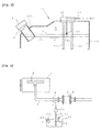
- Fig. 1 shows a breather pipe structure for a liquid reducing agent storage tank according to an embodiment of this invention.
- the liquid reducing agent storage tank 10 is provided with a liquid reducing agent supply pipe, and is configured, as described in relation to Fig. 4 , to pressure-feed a liquid reducing agent 5 from a liquid feeding pump 11 to an injection nozzle 7 via a liquid reducing agent supply pipe 9 such that the liquid reducing agent 5 consisting of a urea aqueous solution (with a concentration of 32. 5%) to upstream of the SCR device 4.
- a sidewall 10r on the left side as viewed in Fig. 1 is located on the right side (or on the left side) of a vehicle, while a sidewall 10c on the right side is located on a center side of the vehicle.
- the upper part of the liquid reducing agent storage tank 10 has a topwall 10t on its center side.
- An upper face portion 10u which is slightly lower than the topwall 10t is formed to extend from the topwall 10t toward the right side (or the left side) via an inclined portion 10i.
- a filler pipe 12 for injection of the liquid reducing agent 5 is provided at an upper edge 10e between the upper face portion 10u and the left-side sidewall 10r such that the filler pipe 12 is inclined obliquely upward by about 45 degrees, and a cap 13 is attached to close an inlet 12f of the filler pipe 12 by being screwed, for example.
- a pipe unit 15 is provided on the topwall 10t of the liquid reducing agent storage tank 10, and the pipe unit 15 is provided with a liquid reducing agent defrosting piping for defrosting the frozen liquid reducing agent 5 in the liquid reducing agent storage tank 10.
- This liquid reducing agent defrosting piping is constituted by a piping having a heater provided therein, or by an engine coolant piping 16 formed into a U-shape, as shown in Fig. 1 , so that the engine coolant passes therethrough.
- This engine coolant piping 16 is composed of a supply-side engine coolant piping 16s and a discharge-side engine coolant piping 16d.
- the engine coolant (LLC) is fed from the supply-side engine coolant piping 16s to heat the frozen liquid reducing agent 5 and discharged through the discharge-side engine coolant piping 16d.
- the pipe unit 15 is provide with a breather pipe 20 for introducing and discharging air into and from a gas-phase region G in the liquid reducing agent storage tank 10.
- An end 20b of the breather pipe 20 that is located outside the liquid reducing agent storage tank 10 is open to the atmosphere, while a breather pipe section 20a located within the tank is bent so as to extend along the supply-side engine coolant piping 16s.
- the lower end 20c of the breather pipe section 20a within the tank is positioned at the same level as the liquid surface L when the tank is full.
- the position of the lower end 20c of the breather pipe 20 is set to be equal to or higher than the liquid surface level L min where the lower open end 12a of the filler pipe 12 is closed, and to be equal to or lower than the liquid surface level L max where the liquid overflows from the inlet 12f at the upper end of the filler pipe 12, and this position of the lower end 20c is defined as the full-tank liquid surface L.
- An air vent orifice 22 is further provided in the breather pipe section 20a above the full-tank liquid surface L. This air vent orifice 22 is formed to have such a diameter that air in the liquid reducing agent storage tank 10 will not be pushed out through the breather pipe 20 during injection of the liquid reducing agent 5.
- the liquid reducing agent 5 is supplied to upstream of the SCR device, and the liquid surface level of the liquid reducing agent 5 in the liquid reducing agent storage tank 10 descends. Nevertheless, the pressure in the liquid reducing agent storage tank 10 is maintained at the atmospheric pressure since air is supplied into the gas-phase region G through the breather pipe 20.
- the frozen liquid reducing agent 5c can be quickly defrosted and the clog of the breather pipe 20 can be cleared by heat of the engine coolant flowing through the supply-side engine coolant piping 16s of the engine coolant piping 16, which makes it possible to introduce and discharge air through the breather pipe 20. Accordingly, the liquid reducing agent 5 can be supplied to the urea SCR system without any trouble that might be caused by the air in the liquid reducing agent storage tank 10 that cannot be released.
- an air vent orifice 22 is provided in the breather pipe 20 at a position above the full-tank liquid surface L in preparation for an emergency until the clog in the breather pipe 20 is cleared, and this air vent orifice 22 has such a diameter that the air in the liquid reducing agent storage tank 10 is not pushed out through the breather pipe 20 when the liquid reducing agent is injected.
- This makes it possible to breathe through the air vent orifice 22 and to prevent hermetic sealing of the gas-phase region G.
- the SCR system is ensured to be able to suck the liquid reducing agent 5 in an emergency.
- the air vent orifice 22 is formed to have such a diameter that the air in the liquid reducing agent storage tank10 is not pushed out through the breather pipe 20, this air vent orifice 22 functions as resistance when the air in the gas-phase region G is discharged from the breather pipe 20 through the air vent orifice 22 when the liquid reducing agent 5 is injected from the filler pipe 12 and the liquid surface reaches the level of the lower end 20c of the breather pipe 20, that is, the full-tank liquid surface L. This makes it possible to control the position of the full-tank liquid surface L.
- the air vent orifice 22 functions as resistance during discharge of air and makes it possible to control the position of the full-tank liquid surface L, it is possible to breathe through the air vent orifice 22. Therefore, the liquid reducing agent 5 can be injected into the tank 10 until the liquid surface reaches the full-tank liquid surface L even if the breather pipe 20 is clogged with frozen liquid reducing agent 5c. In this case, the liquid reducing agent 5 can be injected gradually from the filler pipe 12 after the liquid surface reaches the liquid surface level L min where the lower end of the filler pipe 12 is closed, so that the air can be discharged through the air vent orifice 22 to enable the liquid reducing agent 5 to be injected until its liquid surface level reaches the full-tank liquid surface L.
- the breather pipe 20 for introducing/discharging air in the liquid reducing agent storage tank 10 according to change of the surface level of the liquid reducing agent 5 in the tank is provided such that its lower end 20c extends along a liquid reducing agent defrosting piping such as the engine coolant piping 16.
- a liquid reducing agent defrosting piping such as the engine coolant piping 16.
Landscapes
- Chemical & Material Sciences (AREA)
- Engineering & Computer Science (AREA)
- Chemical Kinetics & Catalysis (AREA)
- Health & Medical Sciences (AREA)
- Toxicology (AREA)
- Combustion & Propulsion (AREA)
- Mechanical Engineering (AREA)
- General Engineering & Computer Science (AREA)
- Exhaust Gas After Treatment (AREA)
Abstract
Description
- This invention relates to a liquid reducing agent storage tank for storing a liquid reducing agent for reducing NOx in engine exhaust gas, and in particular to a breather pipe structure for a liquid reducing agent storage tank for introducing/discharging air according to an amount of liquid stored in the liquid reducing agent storage tank.
- Exhaust gas purification systems which have been developed for purifying NOx in diesel engine exhaust gas include, for example, a urea SCR system using a selective catalytic reduction (SCR) (see, for example,
Patent Documents 1 and 2). - This urea SCR system is configured to supply an aqueous urea solution (with a urea concentration of 32.5%), for example, serving as a liquid reducing agent to an upstream pat in the direction of exhaust gas flow of the SCR device, so that urea is hydrolyzed to generate ammonia by heat of the exhaust gas, and NOx is reduced by this ammonia on a SCR catalyst.
- As shown in
Fig. 4 , anexhaust pipe 3 is connected to anexhaust manifold 2 of adiesel engine 1. A SCR device 4 for NOx reduction is connected to the middle of theexhaust pipe 3, and a reducing agent supply pipe section 8 having aninjection nozzle 7 for supplying a liquid reducing agent (urea aqueous solution) 5 to aSCR catalyst 6 in the SCR device 4 is connected to an upstream part in the direction of exhaust gas flow in the SCR device 4. - A liquid reducing
agent storage tank 10 is connected to theinjection nozzle 7 of the reducing agent supply pipe section 8 via a liquid reducing agent supply pipe 9. This liquid reducingagent storage tank 10 is configured to pressure feed the liquid reducingagent 5 from aliquid feeding pump 11 to theinjection nozzle 7 via the liquid reducing agent supply pipe 9. - The liquid reducing
agent storage tank 10 is provided with afiller pipe 12, so that thetank 10 is refilled with the liquid reducingagent 5 through thefiller pipe 12 after removing acap 13 provided on thefiller pipe 12. - This liquid reducing
agent storage tank 10 is installed in a small place on a side of a vehicle in the vicinity of theexhaust pipe 3, and thefiller pipe 12 is attached to an upper edge 10e of the liquid reducingagent storage tank 10 on the vehicle side such that thefiller pipe 12 is inclined obliquely upward to facilitate the injection of the liquid reducingagent 5. - Further, a
breather pipe 14 is provided on top of the liquid reducingagent storage tank 10 in order to introduce air from the outside and to discharge air according to change of the liquid surface level in the tank. -
- Patent Document 1: Japanese Patent Application Laid-open No.
2000-27627 - Patent Document 2: Japanese Patent Application Laid-open No.
2005-83223 - In very cold climate, urea aqueous solution serving as the liquid reducing
agent 5 will freeze at eleven degrees Celsius below zero. For this reason, as shown inFig. 3 , apipe unit 15 on top of the liquid reducingagent storage tank 10 is provided with anengine coolant piping 16 formed into a U-shape or the like in order to defrost the liquid reducingagent 5 in the liquid reducingagent storage tank 10, so that the frozen liquid reducingagent 5 can be defrosted by feeding an engine coolant (LLC) from a supply-side engine coolant piping 16s to a discharge-side engine coolant piping 16d. - However, in this case, even though the liquid reducing
agent 5 in the liquid reducingagent storage tank 10 can be defrosted, the liquid reducingagent 5c frozen in alower end 14c of thebreather pipe 14 as shown inFig. 3 andFig. 2(b) cannot be defrosted by theengine coolant piping 16, and thebreather pipe 14 remains clogged with the frozen liquid reducingagent 5c. If a gas-phase region G in the liquid reducingagent storage tank 10 is hermetically sealed, theliquid feeding pump 11 of the SCR system becomes unable to suck the liquid reducingagent 5 and the liquid reducingagent 5 cannot be injected. - It is therefore an object the invention to solve the aforementioned problems, and to provide a breather pipe structure for a liquid reducing agent storage tank which does not obstruct the supply of a liquid reducing agent even if the breather pipe of the liquid reducing agent storage tank is clogged with frozen liquid reducing agent.
- In order to achieve the object described above, this invention provides a breather pipe structure for a liquid reducing agent storage tank for storing a liquid reducing agent, having a breather pipe for introducing/discharging air attached on top of the liquid reducing agent storage tank, wherein a lower end of the breather pipe in the liquid reducing agent storage tank is arranged to extend along a liquid reducing agent defrosting piping provided in the liquid reducing agent storage tank.
- In this invention, an air vent orifice may be provided in the breather pipe.
- In this invention, a lower end of the breather pipe may be positioned between a liquid surface level at which a lower open end of the filler pipe is closed and a liquid surface level at which the liquid overflows from an inlet at the upper end of the filler pipe.
- In this invention, the air vent orifice may be formed to have such a diameter that air in the liquid reducing agent storage tank will not be fushed out through the breather pipe during injection of the liquid reducing agent.
- In this invention, the liquid reducing agent defrosting piping is constituted by an engine coolant piping for feeding an engine coolant.
- According to this invention, the breather pipe is arranged along the liquid reducing agent defrosting piping provided in the liquid reducing agent storage tank, whereby even if any liquid reducing agent is frozen within the breather pipe, the frozen liquid reducing agent can be defrosted. Further, the breather pipe is provided with an air vent orifice, whereby even if the breather pipe is clogged with the frozen liquid reducing agent, the liquid reducing agent can be fed without difficulty. These are the advantageous effects offered by the invention.
-
-
Fig. 1 is a cross-sectional view showing an embodiment of this invention. -
Fig. 2 is an enlarged view showing a breather pipe according to the invention and a breather pipe according to prior art. -
Fig. 3 is a diagram showing a conventional breather pipe structure for a liquid reducing agent storage tank. -
Fig. 4 is a diagram illustrating a urea SCR system to which a liquid reducing agent storage tank is applied. - A preferred embodiment of the invention will be described in detail with reference to the accompanying drawings.
-
Fig. 1 shows a breather pipe structure for a liquid reducing agent storage tank according to an embodiment of this invention. - Although omitted in
Fig. 1 , the liquid reducingagent storage tank 10 is provided with a liquid reducing agent supply pipe, and is configured, as described in relation toFig. 4 , to pressure-feed a liquid reducingagent 5 from aliquid feeding pump 11 to aninjection nozzle 7 via a liquid reducing agent supply pipe 9 such that the liquid reducingagent 5 consisting of a urea aqueous solution (with a concentration of 32. 5%) to upstream of the SCR device 4. - Although in
Fig. 1 only an upper part of the liquid reducingagent storage tank 10 is shown with a lower part being omitted, a sidewall 10r on the left side as viewed inFig. 1 is located on the right side (or on the left side) of a vehicle, while a sidewall 10c on the right side is located on a center side of the vehicle. The upper part of the liquid reducingagent storage tank 10 has a topwall 10t on its center side. Anupper face portion 10u which is slightly lower than the topwall 10t is formed to extend from the topwall 10t toward the right side (or the left side) via an inclined portion 10i. Afiller pipe 12 for injection of the liquid reducingagent 5 is provided at an upper edge 10e between theupper face portion 10u and the left-side sidewall 10r such that thefiller pipe 12 is inclined obliquely upward by about 45 degrees, and acap 13 is attached to close an inlet 12f of thefiller pipe 12 by being screwed, for example. - A
pipe unit 15 is provided on the topwall 10t of the liquid reducingagent storage tank 10, and thepipe unit 15 is provided with a liquid reducing agent defrosting piping for defrosting the frozen liquid reducingagent 5 in the liquid reducingagent storage tank 10. This liquid reducing agent defrosting piping is constituted by a piping having a heater provided therein, or by anengine coolant piping 16 formed into a U-shape, as shown inFig. 1 , so that the engine coolant passes therethrough. Thisengine coolant piping 16 is composed of a supply-side engine coolant piping 16s and a discharge-side engine coolant piping 16d. The engine coolant (LLC) is fed from the supply-side engine coolant piping 16s to heat the frozen liquid reducingagent 5 and discharged through the discharge-side engine coolant piping 16d. - The
pipe unit 15 is provide with abreather pipe 20 for introducing and discharging air into and from a gas-phase region G in the liquid reducingagent storage tank 10. Anend 20b of thebreather pipe 20 that is located outside the liquid reducingagent storage tank 10 is open to the atmosphere, while abreather pipe section 20a located within the tank is bent so as to extend along the supply-side engine coolant piping 16s. Thelower end 20c of thebreather pipe section 20a within the tank is positioned at the same level as the liquid surface L when the tank is full. - The position of the
lower end 20c of thebreather pipe 20 is set to be equal to or higher than the liquid surface level Lmin where the lower open end 12a of thefiller pipe 12 is closed, and to be equal to or lower than the liquid surface level Lmax where the liquid overflows from the inlet 12f at the upper end of thefiller pipe 12, and this position of thelower end 20c is defined as the full-tank liquid surface L. - An
air vent orifice 22 is further provided in thebreather pipe section 20a above the full-tank liquid surface L. Thisair vent orifice 22 is formed to have such a diameter that air in the liquid reducingagent storage tank 10 will not be pushed out through thebreather pipe 20 during injection of the liquid reducingagent 5. - Next, functions of the invention will be described.
- When the urea SCR system is being operated by a SCR device during ordinary use thereof, the liquid reducing
agent 5 is supplied to upstream of the SCR device, and the liquid surface level of the liquid reducingagent 5 in the liquid reducingagent storage tank 10 descends. Nevertheless, the pressure in the liquid reducingagent storage tank 10 is maintained at the atmospheric pressure since air is supplied into the gas-phase region G through thebreather pipe 20. - When the
lower end 20c of thebreather pipe 20 is clogged with frozen liquid reducingagent 5c, as shown inFig. 2 (a) during use of the SCR device in very cold climate, the frozen liquid reducingagent 5c can be quickly defrosted and the clog of thebreather pipe 20 can be cleared by heat of the engine coolant flowing through the supply-side engine coolant piping 16s of theengine coolant piping 16, which makes it possible to introduce and discharge air through thebreather pipe 20. Accordingly, the liquid reducingagent 5 can be supplied to the urea SCR system without any trouble that might be caused by the air in the liquid reducingagent storage tank 10 that cannot be released. - In contrast, in the case of the
conventional breather pipe 14 shown inFig. 2(b) , when thelower end 14c thereof is clogged with frozen liquid reducingagent 5c, the engine coolant fed through the supply-side engine coolant piping 16s of theengine coolant piping 16 cannot defrost the frozen liquid reducingagent 5c in thelower end 14c of thebreather pipe 14 even though it can defrost the liquid reducingagent 5 in the liquid reducingagent storage tank 10. As a result, the liquid reducingagent 5 cannot be supplied to the urea SCR system. - Further, in this invention, an
air vent orifice 22 is provided in thebreather pipe 20 at a position above the full-tank liquid surface L in preparation for an emergency until the clog in thebreather pipe 20 is cleared, and thisair vent orifice 22 has such a diameter that the air in the liquid reducingagent storage tank 10 is not pushed out through thebreather pipe 20 when the liquid reducing agent is injected. This makes it possible to breathe through theair vent orifice 22 and to prevent hermetic sealing of the gas-phase region G. Thus, the SCR system is ensured to be able to suck the liquid reducingagent 5 in an emergency. - Further, since the
air vent orifice 22 is formed to have such a diameter that the air in the liquid reducing agent storage tank10 is not pushed out through thebreather pipe 20, thisair vent orifice 22 functions as resistance when the air in the gas-phase region G is discharged from thebreather pipe 20 through theair vent orifice 22 when theliquid reducing agent 5 is injected from thefiller pipe 12 and the liquid surface reaches the level of thelower end 20c of thebreather pipe 20, that is, the full-tank liquid surface L. This makes it possible to control the position of the full-tank liquid surface L. - While the
air vent orifice 22 functions as resistance during discharge of air and makes it possible to control the position of the full-tank liquid surface L, it is possible to breathe through theair vent orifice 22. Therefore, theliquid reducing agent 5 can be injected into thetank 10 until the liquid surface reaches the full-tank liquid surface L even if thebreather pipe 20 is clogged with frozenliquid reducing agent 5c. In this case, theliquid reducing agent 5 can be injected gradually from thefiller pipe 12 after the liquid surface reaches the liquid surface level Lmin where the lower end of thefiller pipe 12 is closed, so that the air can be discharged through theair vent orifice 22 to enable theliquid reducing agent 5 to be injected until its liquid surface level reaches the full-tank liquid surface L. - According to this invention as described above, the
breather pipe 20 for introducing/discharging air in the liquid reducingagent storage tank 10 according to change of the surface level of theliquid reducing agent 5 in the tank is provided such that itslower end 20c extends along a liquid reducing agent defrosting piping such as theengine coolant piping 16. Thus, even if theliquid reducing agent 5c is frozen in thelower end 20c to clog thebreather pipe 20, the frozenliquid reducing agent 5c can be defrosted. Since air can be introduced into the gas-phase region G from thebreather pipe 20 via theair vent orifice 22 until the frozenliquid reducing agent 5c is defrosted, the urea SCR system is ensured to be able to suck theliquid reducing agent 5 for an emergency. -
- 5
- Liquid reducing agent
- 10
- Liquid reducing agent storage tank
- 20
- Breather pipe
- 20c
- Lower end
- 22
- Air vent orifice
Claims (5)
- A breather pipe structure for a liquid reducing agent storage tank which stores a liquid reducing agent, and which has a breather pipe for introducing/discharging air attached on top of the liquid reducing agent storage tank, wherein
a lower end of the breather pipe in the liquid reducing agent storage tank is arranged to extend along a liquid reducing agent defrosting piping provided in the liquid reducing agent storage tank. - The breather pipe structure for a liquid reducing agent storage tank according to claim 1, wherein the breather pipe is provided with an air vent orifice.
- The breather pipe structure for a liquid reducing agent storage tank according to claim 1, wherein the lower end of the breather pipe is positioned between a liquid surface level at which a lower open end of the filler pipe is closed and a liquid surface level at which the liquid overflows from an inlet at the upper end of the filler pipe.
- The breather pipe structure for a liquid reducing agent storage tank according to claim 2, wherein the air vent orifice is formed to have such a diameter that air in the liquid reducing agent storage tank is not pushed out through the breather pipe during injection of the liquid reducing agent.
- The breather pipe structure for a liquid reducing agent storage tank according to claim 1, wherein the liquid reducing agent defrosting piping is constituted by an engine coolant piping for feeding an engine coolant.
Applications Claiming Priority (2)
| Application Number | Priority Date | Filing Date | Title |
|---|---|---|---|
| JP2010042744A JP5564989B2 (en) | 2010-02-26 | 2010-02-26 | Breather pipe structure of liquid reductant storage tank |
| PCT/JP2011/053983 WO2011105427A1 (en) | 2010-02-26 | 2011-02-23 | Breather pipe structure for a liquid reductant storage tank |
Publications (3)
| Publication Number | Publication Date |
|---|---|
| EP2541008A1 true EP2541008A1 (en) | 2013-01-02 |
| EP2541008A4 EP2541008A4 (en) | 2014-04-09 |
| EP2541008B1 EP2541008B1 (en) | 2015-08-26 |
Family
ID=44506830
Family Applications (1)
| Application Number | Title | Priority Date | Filing Date |
|---|---|---|---|
| EP11747387.6A Active EP2541008B1 (en) | 2010-02-26 | 2011-02-23 | Breather pipe structure for a liquid reductant storage tank |
Country Status (5)
| Country | Link |
|---|---|
| US (1) | US9964015B2 (en) |
| EP (1) | EP2541008B1 (en) |
| JP (1) | JP5564989B2 (en) |
| CN (1) | CN102791974B (en) |
| WO (1) | WO2011105427A1 (en) |
Families Citing this family (6)
| Publication number | Priority date | Publication date | Assignee | Title |
|---|---|---|---|---|
| JP5784425B2 (en) * | 2011-09-06 | 2015-09-24 | 日野自動車株式会社 | Breather hose for urea water tank |
| CN102817679B (en) * | 2012-08-22 | 2015-08-26 | 东莞正扬电子机械有限公司 | The urea box of anti-filling overfill |
| JP6218674B2 (en) * | 2014-05-28 | 2017-10-25 | 株式会社クボタ | Work vehicle |
| WO2015191885A1 (en) * | 2014-06-11 | 2015-12-17 | Rmb Products, Inc. | Phase-change accommodating rigid fluid container with manipulating assisting recesses |
| FR3023219B1 (en) * | 2014-07-01 | 2016-07-15 | Peugeot Citroen Automobiles Sa | AUTOMOTIVE VEHICLE REAR WING HAVING A SELECTIVE CATALYTIC REDUCTION FLUID RESERVOIR |
| KR102488590B1 (en) * | 2018-07-11 | 2023-01-16 | 엘에스엠트론 주식회사 | Urea storage device |
Family Cites Families (19)
| Publication number | Priority date | Publication date | Assignee | Title |
|---|---|---|---|---|
| US3500843A (en) * | 1967-10-02 | 1970-03-17 | Charles Eugene White | Fuel tank assembly with gravity vent valve |
| DE3540740A1 (en) * | 1985-11-16 | 1987-05-21 | Porsche Ag | FUEL CONNECTOR FOR A FUEL TANK, ESPECIALLY FOR FUEL VEHICLES |
| JPH07119556A (en) * | 1993-10-22 | 1995-05-09 | Honda Motor Co Ltd | Evaporative emission control device |
| US6063350A (en) * | 1997-04-02 | 2000-05-16 | Clean Diesel Technologies, Inc. | Reducing nox emissions from an engine by temperature-controlled urea injection for selective catalytic reduction |
| JP2000027627A (en) | 1998-07-13 | 2000-01-25 | Hino Motors Ltd | Reducing agent warming device for exhaust gas purifying catalyst and exhaust gas purifying device incorporating the same |
| CA2378905C (en) * | 2001-03-27 | 2009-09-08 | Jack Lange | Fuel conduction system |
| JP2002371933A (en) * | 2001-06-14 | 2002-12-26 | Honda Motor Co Ltd | Car fuel tank |
| US6852292B2 (en) * | 2002-04-24 | 2005-02-08 | Kleenair Systems, Inc. | Ammonia storage and injection in NOx control |
| US6810661B2 (en) * | 2002-08-09 | 2004-11-02 | Ford Global Technologies, Llc | Method and system for freeze protecting liquid NOx reductants for vehicle application |
| US7040084B2 (en) * | 2002-12-16 | 2006-05-09 | General Motors Corporation | Exhaust emission aftertreatment |
| JP3751962B2 (en) * | 2003-09-05 | 2006-03-08 | 日産ディーゼル工業株式会社 | Engine exhaust purification system |
| US7594393B2 (en) * | 2004-09-07 | 2009-09-29 | Robert Bosch Gmbh | Apparatus for introducing a reducing agent into the exhaust of an internal combustion engine |
| WO2006131201A2 (en) * | 2005-06-04 | 2006-12-14 | Eichenauer Heizelemente Gmbh & Co.Kg | Urea supply system for a waste gas cleaning catalyst and suitable heating element therefor |
| DE102005037201A1 (en) * | 2005-08-06 | 2007-02-22 | Eichenauer Heizelemente Gmbh & Co. Kg | heating system |
| JP2007262900A (en) * | 2006-03-27 | 2007-10-11 | Nissan Diesel Motor Co Ltd | Vehicular liquid tank and exhaust emission control device of engine having the tank |
| JP4845012B2 (en) * | 2006-03-31 | 2011-12-28 | Udトラックス株式会社 | Breather device for liquid tank and exhaust purification device for engine |
| JP2008008238A (en) * | 2006-06-30 | 2008-01-17 | Toyota Motor Corp | Fuel tank system |
| US20100050606A1 (en) * | 2008-09-04 | 2010-03-04 | Fulks Gary C | Urea tank assembly |
| US20100154907A1 (en) * | 2008-12-18 | 2010-06-24 | Delphi Technologies, Inc. | Urea storage system |
-
2010
- 2010-02-26 JP JP2010042744A patent/JP5564989B2/en not_active Expired - Fee Related
-
2011
- 2011-02-23 CN CN201180011275.XA patent/CN102791974B/en active Active
- 2011-02-23 WO PCT/JP2011/053983 patent/WO2011105427A1/en not_active Ceased
- 2011-02-23 US US13/580,774 patent/US9964015B2/en not_active Expired - Fee Related
- 2011-02-23 EP EP11747387.6A patent/EP2541008B1/en active Active
Also Published As
| Publication number | Publication date |
|---|---|
| EP2541008B1 (en) | 2015-08-26 |
| CN102791974B (en) | 2015-06-03 |
| US20120318813A1 (en) | 2012-12-20 |
| JP5564989B2 (en) | 2014-08-06 |
| JP2011179362A (en) | 2011-09-15 |
| CN102791974A (en) | 2012-11-21 |
| WO2011105427A1 (en) | 2011-09-01 |
| EP2541008A4 (en) | 2014-04-09 |
| US9964015B2 (en) | 2018-05-08 |
Similar Documents
| Publication | Publication Date | Title |
|---|---|---|
| US9404408B2 (en) | Device and method for metering a reducing agent into an exhaust gas system of a motor vehicle | |
| EP2541008B1 (en) | Breather pipe structure for a liquid reductant storage tank | |
| KR101080557B1 (en) | Dosing system and method for the operation of a dosing system | |
| EP2541007A1 (en) | Breather pipe structure for a liquid reductant storage tank | |
| US7886525B2 (en) | Exhaust gas purification device of internal combustion engine | |
| KR101260083B1 (en) | System for storing an additive and for injecting it into engine exhaust gases | |
| US9169760B2 (en) | Conveying unit for conveying reducing agent | |
| EP2917524B1 (en) | Plastic tank for an operating fluid | |
| CN105247181B (en) | Urea water injection mouth | |
| CN101263022A (en) | Motor vehicle storage tanks for liquid reducing agents, especially urea solutions | |
| CN103620174B (en) | Injection device for injecting fluid | |
| WO2011078235A1 (en) | Atmospheric vent structure for reducing agent tank | |
| CN102439267A (en) | Liquid tank with ventilation system | |
| KR20130013487A (en) | Selective catalytic reduction | |
| KR101619641B1 (en) | An urea backflow prevention apparatus of scr and a control method thereof | |
| US20150361854A1 (en) | Diesel exhaust fluid tank housing | |
| KR101637722B1 (en) | An urea backflow prevention apparatus of scr and a control method thereof | |
| KR101900623B1 (en) | Exhaust purifier | |
| EP2905443B1 (en) | Exhaust gas purification apparatus for an internal combustion engine | |
| US10914216B2 (en) | Delivery module for a metering system for metering a reducing agent into the exhaust gas section of a motor vehicle, and metering system | |
| US20160222859A1 (en) | Method and system for detecting malfunctioning of fluid tank of machine | |
| KR101965853B1 (en) | Urea water solution supply apparatus for exhaust gas purification | |
| JP2010255521A (en) | Reducing agent supply device | |
| KR101896554B1 (en) | Urea water solution supply apparatus and method for exhaust gas aftertreatment system | |
| JP2020051315A (en) | Reducing agent supply device |
Legal Events
| Date | Code | Title | Description |
|---|---|---|---|
| PUAI | Public reference made under article 153(3) epc to a published international application that has entered the european phase |
Free format text: ORIGINAL CODE: 0009012 |
|
| 17P | Request for examination filed |
Effective date: 20120904 |
|
| AK | Designated contracting states |
Kind code of ref document: A1 Designated state(s): AL AT BE BG CH CY CZ DE DK EE ES FI FR GB GR HR HU IE IS IT LI LT LU LV MC MK MT NL NO PL PT RO RS SE SI SK SM TR |
|
| DAX | Request for extension of the european patent (deleted) | ||
| REG | Reference to a national code |
Ref country code: DE Ref legal event code: R079 Ref document number: 602011019185 Country of ref document: DE Free format text: PREVIOUS MAIN CLASS: F01N0003080000 Ipc: F01N0003200000 |
|
| A4 | Supplementary search report drawn up and despatched |
Effective date: 20140307 |
|
| RIC1 | Information provided on ipc code assigned before grant |
Ipc: F01N 3/20 20060101AFI20140304BHEP |
|
| GRAP | Despatch of communication of intention to grant a patent |
Free format text: ORIGINAL CODE: EPIDOSNIGR1 |
|
| INTG | Intention to grant announced |
Effective date: 20150305 |
|
| GRAS | Grant fee paid |
Free format text: ORIGINAL CODE: EPIDOSNIGR3 |
|
| GRAA | (expected) grant |
Free format text: ORIGINAL CODE: 0009210 |
|
| AK | Designated contracting states |
Kind code of ref document: B1 Designated state(s): AL AT BE BG CH CY CZ DE DK EE ES FI FR GB GR HR HU IE IS IT LI LT LU LV MC MK MT NL NO PL PT RO RS SE SI SK SM TR |
|
| REG | Reference to a national code |
Ref country code: GB Ref legal event code: FG4D |
|
| REG | Reference to a national code |
Ref country code: CH Ref legal event code: EP |
|
| REG | Reference to a national code |
Ref country code: AT Ref legal event code: REF Ref document number: 745309 Country of ref document: AT Kind code of ref document: T Effective date: 20150915 |
|
| REG | Reference to a national code |
Ref country code: IE Ref legal event code: FG4D |
|
| REG | Reference to a national code |
Ref country code: DE Ref legal event code: R096 Ref document number: 602011019185 Country of ref document: DE |
|
| REG | Reference to a national code |
Ref country code: SE Ref legal event code: TRGR |
|
| REG | Reference to a national code |
Ref country code: AT Ref legal event code: MK05 Ref document number: 745309 Country of ref document: AT Kind code of ref document: T Effective date: 20150826 |
|
| REG | Reference to a national code |
Ref country code: LT Ref legal event code: MG4D |
|
| PG25 | Lapsed in a contracting state [announced via postgrant information from national office to epo] |
Ref country code: NO Free format text: LAPSE BECAUSE OF FAILURE TO SUBMIT A TRANSLATION OF THE DESCRIPTION OR TO PAY THE FEE WITHIN THE PRESCRIBED TIME-LIMIT Effective date: 20151126 Ref country code: GR Free format text: LAPSE BECAUSE OF FAILURE TO SUBMIT A TRANSLATION OF THE DESCRIPTION OR TO PAY THE FEE WITHIN THE PRESCRIBED TIME-LIMIT Effective date: 20151127 Ref country code: LV Free format text: LAPSE BECAUSE OF FAILURE TO SUBMIT A TRANSLATION OF THE DESCRIPTION OR TO PAY THE FEE WITHIN THE PRESCRIBED TIME-LIMIT Effective date: 20150826 Ref country code: FI Free format text: LAPSE BECAUSE OF FAILURE TO SUBMIT A TRANSLATION OF THE DESCRIPTION OR TO PAY THE FEE WITHIN THE PRESCRIBED TIME-LIMIT Effective date: 20150826 Ref country code: LT Free format text: LAPSE BECAUSE OF FAILURE TO SUBMIT A TRANSLATION OF THE DESCRIPTION OR TO PAY THE FEE WITHIN THE PRESCRIBED TIME-LIMIT Effective date: 20150826 |
|
| REG | Reference to a national code |
Ref country code: NL Ref legal event code: MP Effective date: 20150826 |
|
| PG25 | Lapsed in a contracting state [announced via postgrant information from national office to epo] |
Ref country code: HR Free format text: LAPSE BECAUSE OF FAILURE TO SUBMIT A TRANSLATION OF THE DESCRIPTION OR TO PAY THE FEE WITHIN THE PRESCRIBED TIME-LIMIT Effective date: 20150826 Ref country code: IS Free format text: LAPSE BECAUSE OF FAILURE TO SUBMIT A TRANSLATION OF THE DESCRIPTION OR TO PAY THE FEE WITHIN THE PRESCRIBED TIME-LIMIT Effective date: 20151226 Ref country code: AT Free format text: LAPSE BECAUSE OF FAILURE TO SUBMIT A TRANSLATION OF THE DESCRIPTION OR TO PAY THE FEE WITHIN THE PRESCRIBED TIME-LIMIT Effective date: 20150826 Ref country code: ES Free format text: LAPSE BECAUSE OF FAILURE TO SUBMIT A TRANSLATION OF THE DESCRIPTION OR TO PAY THE FEE WITHIN THE PRESCRIBED TIME-LIMIT Effective date: 20150826 Ref country code: PL Free format text: LAPSE BECAUSE OF FAILURE TO SUBMIT A TRANSLATION OF THE DESCRIPTION OR TO PAY THE FEE WITHIN THE PRESCRIBED TIME-LIMIT Effective date: 20150826 Ref country code: PT Free format text: LAPSE BECAUSE OF FAILURE TO SUBMIT A TRANSLATION OF THE DESCRIPTION OR TO PAY THE FEE WITHIN THE PRESCRIBED TIME-LIMIT Effective date: 20151228 Ref country code: RS Free format text: LAPSE BECAUSE OF FAILURE TO SUBMIT A TRANSLATION OF THE DESCRIPTION OR TO PAY THE FEE WITHIN THE PRESCRIBED TIME-LIMIT Effective date: 20150826 |
|
| PG25 | Lapsed in a contracting state [announced via postgrant information from national office to epo] |
Ref country code: NL Free format text: LAPSE BECAUSE OF FAILURE TO SUBMIT A TRANSLATION OF THE DESCRIPTION OR TO PAY THE FEE WITHIN THE PRESCRIBED TIME-LIMIT Effective date: 20150826 |
|
| REG | Reference to a national code |
Ref country code: FR Ref legal event code: PLFP Year of fee payment: 6 |
|
| PG25 | Lapsed in a contracting state [announced via postgrant information from national office to epo] |
Ref country code: SK Free format text: LAPSE BECAUSE OF FAILURE TO SUBMIT A TRANSLATION OF THE DESCRIPTION OR TO PAY THE FEE WITHIN THE PRESCRIBED TIME-LIMIT Effective date: 20150826 Ref country code: EE Free format text: LAPSE BECAUSE OF FAILURE TO SUBMIT A TRANSLATION OF THE DESCRIPTION OR TO PAY THE FEE WITHIN THE PRESCRIBED TIME-LIMIT Effective date: 20150826 Ref country code: DK Free format text: LAPSE BECAUSE OF FAILURE TO SUBMIT A TRANSLATION OF THE DESCRIPTION OR TO PAY THE FEE WITHIN THE PRESCRIBED TIME-LIMIT Effective date: 20150826 Ref country code: CZ Free format text: LAPSE BECAUSE OF FAILURE TO SUBMIT A TRANSLATION OF THE DESCRIPTION OR TO PAY THE FEE WITHIN THE PRESCRIBED TIME-LIMIT Effective date: 20150826 Ref country code: IT Free format text: LAPSE BECAUSE OF FAILURE TO SUBMIT A TRANSLATION OF THE DESCRIPTION OR TO PAY THE FEE WITHIN THE PRESCRIBED TIME-LIMIT Effective date: 20150826 |
|
| REG | Reference to a national code |
Ref country code: DE Ref legal event code: R097 Ref document number: 602011019185 Country of ref document: DE |
|
| PG25 | Lapsed in a contracting state [announced via postgrant information from national office to epo] |
Ref country code: BE Free format text: LAPSE BECAUSE OF NON-PAYMENT OF DUE FEES Effective date: 20160229 Ref country code: RO Free format text: LAPSE BECAUSE OF FAILURE TO SUBMIT A TRANSLATION OF THE DESCRIPTION OR TO PAY THE FEE WITHIN THE PRESCRIBED TIME-LIMIT Effective date: 20150826 |
|
| PLBE | No opposition filed within time limit |
Free format text: ORIGINAL CODE: 0009261 |
|
| STAA | Information on the status of an ep patent application or granted ep patent |
Free format text: STATUS: NO OPPOSITION FILED WITHIN TIME LIMIT |
|
| PGFP | Annual fee paid to national office [announced via postgrant information from national office to epo] |
Ref country code: GB Payment date: 20160422 Year of fee payment: 6 |
|
| 26N | No opposition filed |
Effective date: 20160530 |
|
| PG25 | Lapsed in a contracting state [announced via postgrant information from national office to epo] |
Ref country code: SI Free format text: LAPSE BECAUSE OF FAILURE TO SUBMIT A TRANSLATION OF THE DESCRIPTION OR TO PAY THE FEE WITHIN THE PRESCRIBED TIME-LIMIT Effective date: 20150826 |
|
| PG25 | Lapsed in a contracting state [announced via postgrant information from national office to epo] |
Ref country code: LU Free format text: LAPSE BECAUSE OF FAILURE TO SUBMIT A TRANSLATION OF THE DESCRIPTION OR TO PAY THE FEE WITHIN THE PRESCRIBED TIME-LIMIT Effective date: 20160223 Ref country code: MC Free format text: LAPSE BECAUSE OF FAILURE TO SUBMIT A TRANSLATION OF THE DESCRIPTION OR TO PAY THE FEE WITHIN THE PRESCRIBED TIME-LIMIT Effective date: 20150826 |
|
| REG | Reference to a national code |
Ref country code: CH Ref legal event code: PL |
|
| PG25 | Lapsed in a contracting state [announced via postgrant information from national office to epo] |
Ref country code: LI Free format text: LAPSE BECAUSE OF NON-PAYMENT OF DUE FEES Effective date: 20160229 Ref country code: CH Free format text: LAPSE BECAUSE OF NON-PAYMENT OF DUE FEES Effective date: 20160229 |
|
| REG | Reference to a national code |
Ref country code: IE Ref legal event code: MM4A |
|
| PG25 | Lapsed in a contracting state [announced via postgrant information from national office to epo] |
Ref country code: BE Free format text: LAPSE BECAUSE OF FAILURE TO SUBMIT A TRANSLATION OF THE DESCRIPTION OR TO PAY THE FEE WITHIN THE PRESCRIBED TIME-LIMIT Effective date: 20150826 |
|
| REG | Reference to a national code |
Ref country code: FR Ref legal event code: PLFP Year of fee payment: 7 |
|
| PG25 | Lapsed in a contracting state [announced via postgrant information from national office to epo] |
Ref country code: IE Free format text: LAPSE BECAUSE OF NON-PAYMENT OF DUE FEES Effective date: 20160223 |
|
| PG25 | Lapsed in a contracting state [announced via postgrant information from national office to epo] |
Ref country code: MT Free format text: LAPSE BECAUSE OF FAILURE TO SUBMIT A TRANSLATION OF THE DESCRIPTION OR TO PAY THE FEE WITHIN THE PRESCRIBED TIME-LIMIT Effective date: 20150826 |
|
| GBPC | Gb: european patent ceased through non-payment of renewal fee |
Effective date: 20170223 |
|
| REG | Reference to a national code |
Ref country code: FR Ref legal event code: PLFP Year of fee payment: 8 |
|
| PG25 | Lapsed in a contracting state [announced via postgrant information from national office to epo] |
Ref country code: GB Free format text: LAPSE BECAUSE OF NON-PAYMENT OF DUE FEES Effective date: 20170223 |
|
| PG25 | Lapsed in a contracting state [announced via postgrant information from national office to epo] |
Ref country code: SM Free format text: LAPSE BECAUSE OF FAILURE TO SUBMIT A TRANSLATION OF THE DESCRIPTION OR TO PAY THE FEE WITHIN THE PRESCRIBED TIME-LIMIT Effective date: 20150826 Ref country code: HU Free format text: LAPSE BECAUSE OF FAILURE TO SUBMIT A TRANSLATION OF THE DESCRIPTION OR TO PAY THE FEE WITHIN THE PRESCRIBED TIME-LIMIT; INVALID AB INITIO Effective date: 20110223 Ref country code: CY Free format text: LAPSE BECAUSE OF FAILURE TO SUBMIT A TRANSLATION OF THE DESCRIPTION OR TO PAY THE FEE WITHIN THE PRESCRIBED TIME-LIMIT Effective date: 20150826 |
|
| PG25 | Lapsed in a contracting state [announced via postgrant information from national office to epo] |
Ref country code: TR Free format text: LAPSE BECAUSE OF FAILURE TO SUBMIT A TRANSLATION OF THE DESCRIPTION OR TO PAY THE FEE WITHIN THE PRESCRIBED TIME-LIMIT Effective date: 20150826 Ref country code: MK Free format text: LAPSE BECAUSE OF FAILURE TO SUBMIT A TRANSLATION OF THE DESCRIPTION OR TO PAY THE FEE WITHIN THE PRESCRIBED TIME-LIMIT Effective date: 20150826 Ref country code: MT Free format text: LAPSE BECAUSE OF FAILURE TO SUBMIT A TRANSLATION OF THE DESCRIPTION OR TO PAY THE FEE WITHIN THE PRESCRIBED TIME-LIMIT Effective date: 20160229 |
|
| PG25 | Lapsed in a contracting state [announced via postgrant information from national office to epo] |
Ref country code: BG Free format text: LAPSE BECAUSE OF FAILURE TO SUBMIT A TRANSLATION OF THE DESCRIPTION OR TO PAY THE FEE WITHIN THE PRESCRIBED TIME-LIMIT Effective date: 20150826 |
|
| PG25 | Lapsed in a contracting state [announced via postgrant information from national office to epo] |
Ref country code: AL Free format text: LAPSE BECAUSE OF FAILURE TO SUBMIT A TRANSLATION OF THE DESCRIPTION OR TO PAY THE FEE WITHIN THE PRESCRIBED TIME-LIMIT Effective date: 20150826 |
|
| PGFP | Annual fee paid to national office [announced via postgrant information from national office to epo] |
Ref country code: SE Payment date: 20221229 Year of fee payment: 13 |
|
| PGFP | Annual fee paid to national office [announced via postgrant information from national office to epo] |
Ref country code: FR Payment date: 20230110 Year of fee payment: 13 |
|
| REG | Reference to a national code |
Ref country code: SE Ref legal event code: EUG |
|
| PG25 | Lapsed in a contracting state [announced via postgrant information from national office to epo] |
Ref country code: FR Free format text: LAPSE BECAUSE OF NON-PAYMENT OF DUE FEES Effective date: 20240229 |
|
| PG25 | Lapsed in a contracting state [announced via postgrant information from national office to epo] |
Ref country code: FR Free format text: LAPSE BECAUSE OF NON-PAYMENT OF DUE FEES Effective date: 20240229 |
|
| PG25 | Lapsed in a contracting state [announced via postgrant information from national office to epo] |
Ref country code: SE Free format text: LAPSE BECAUSE OF NON-PAYMENT OF DUE FEES Effective date: 20240224 |
|
| PGFP | Annual fee paid to national office [announced via postgrant information from national office to epo] |
Ref country code: DE Payment date: 20260121 Year of fee payment: 16 |