EP2540983A2 - Radial spline arrangement for LPT vane clusters - Google Patents
Radial spline arrangement for LPT vane clusters Download PDFInfo
- Publication number
- EP2540983A2 EP2540983A2 EP12169688A EP12169688A EP2540983A2 EP 2540983 A2 EP2540983 A2 EP 2540983A2 EP 12169688 A EP12169688 A EP 12169688A EP 12169688 A EP12169688 A EP 12169688A EP 2540983 A2 EP2540983 A2 EP 2540983A2
- Authority
- EP
- European Patent Office
- Prior art keywords
- vane
- case
- splines
- spline
- cluster
- Prior art date
- Legal status (The legal status is an assumption and is not a legal conclusion. Google has not performed a legal analysis and makes no representation as to the accuracy of the status listed.)
- Withdrawn
Links
Images


Classifications
-
- F—MECHANICAL ENGINEERING; LIGHTING; HEATING; WEAPONS; BLASTING
- F01—MACHINES OR ENGINES IN GENERAL; ENGINE PLANTS IN GENERAL; STEAM ENGINES
- F01D—NON-POSITIVE DISPLACEMENT MACHINES OR ENGINES, e.g. STEAM TURBINES
- F01D25/00—Component parts, details, or accessories, not provided for in, or of interest apart from, other groups
- F01D25/24—Casings; Casing parts, e.g. diaphragms, casing fastenings
- F01D25/246—Fastening of diaphragms or stator-rings
-
- Y—GENERAL TAGGING OF NEW TECHNOLOGICAL DEVELOPMENTS; GENERAL TAGGING OF CROSS-SECTIONAL TECHNOLOGIES SPANNING OVER SEVERAL SECTIONS OF THE IPC; TECHNICAL SUBJECTS COVERED BY FORMER USPC CROSS-REFERENCE ART COLLECTIONS [XRACs] AND DIGESTS
- Y10—TECHNICAL SUBJECTS COVERED BY FORMER USPC
- Y10T—TECHNICAL SUBJECTS COVERED BY FORMER US CLASSIFICATION
- Y10T29/00—Metal working
- Y10T29/49—Method of mechanical manufacture
- Y10T29/49316—Impeller making
- Y10T29/4932—Turbomachine making
- Y10T29/49321—Assembling individual fluid flow interacting members, e.g., blades, vanes, buckets, on rotary support member
Definitions
- the present invention relates generally to gas turbine engines, and more particularly to the attachment of a full hoop stator vane cluster to a case of a gas turbine engine.
- a gas turbine engine typically includes a high pressure spool, a combustion system and a low pressure spool disposed within an engine case to form a generally axial, serial flow path about the engine centerline.
- the high pressure spool includes a high pressure turbine, a high pressure shaft extending axially forward from the high pressure turbine, and a high pressure compressor connected to a forward end of the high pressure shaft.
- the low pressure spool includes a low pressure turbine, which is disposed downstream of the high pressure turbine, a low pressure shaft, which typically extends coaxially through the high pressure shaft, and a low pressure compressor connected to a forward end of the low pressure shaft, forward of the high pressure compressor.
- the combustion system is disposed between the high pressure compressor and the high pressure turbine and receives compressed air from the compressors and fuel provided by a fuel injection system.
- a combustion process is carried out within the combustion system to produce high energy gases to produce thrust and turn the high and low pressure turbines, which drive the compressors to sustain the combustion process.
- Turbines are comprised of alternating stages of blades and airfoils that are arranged radially around a center axis of the engine within the axial flow path of the engine case. More specifically, the blades are attached to a support rotor and the airfoils are attached to the engine case. When high energy gases pass through a turbine, heat is transferred to the airfoils and the case. Due to local gas flow paths and component features and geometry, thermal expansion is not equal over the entire turbine section. Similarly, the case and the airfoils may not expand equally during operation and contract equally after operation. This phenomenon can cause thermal stresses and crack formation that can lead to failure of the components.
- a full hoop stator vane cluster includes an inner hoop and an outer hoop both being substantially cylindrical and coaxial. A plurality of outward from the outer hoop for attaching the vane cluster to a gas turbine engine.
- a gas turbine engine in another embodiment, includes a full hoop stator vane cluster and a case.
- the full hoop stator vane cluster includes an inner hoop and an outer hoop both being substantially cylindrical and coaxial.
- a plurality of airfoils extend radially between the hoops, and a plurality of vane splines extend radially outward from the outer hoop for attaching the vane cluster to a gas turbine engine.
- the case is substantially cylindrical and has a plurality of case splines extending radially inward for attaching the vane cluster.
- a method of installing a full hoop stator vane cluster into a gas turbine engine includes inserting the vane cluster axially into a case of the gas turbine engine. Also included are moving a plurality of vane splines on the vane cluster alongside a plurality of case splines on the case and circumferentially offsetting the vane splines and the case splines. Further included are rotating the vane cluster such that the vane splines are circumferentially aligned with the case splines and attaching a vane spline to a case spline to substantially restrain relative axial and circumferential movement.
- FIG. 1 is a schematic cross-section view of a gas turbine engine showing a vane cluster.
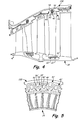
- FIG. 2 is a perspective view of the vane cluster showing vane splines.
- FIG. 3A is a partial perspective view of the vane cluster and a low pressure turbine case.
- FIG. 3B is a partial perspective view of the vane cluster attached to the low pressure turbine case.
- FIG. 4 is a partial cross-section view along line 4 in FIG. 1 showing the vane cluster attached to the low pressure turbine case.
- FIG. 5 is a perspective view of a vane cluster having alternate embodiment vane splines and a low pressure turbine case having alternate embodiment case splines.
- FIG. 1 shows a cross section of gas turbine engine 10 in which a vane cluster of the present invention is used.
- FIG. 1 depicts a gas turbine engine typically used for aircraft propulsion, the invention is readily applicable to gas turbine generators and other similar systems incorporating rotor-supported, shaft-driven turbines. Shown in FIG.
- gas turbine engine 10 gas turbine engine 10, fan 12, low pressure compressor (LPC) 14, high pressure compressor (HPC) 16, combustor section 18, high pressure turbine (HPT) 20, low pressure turbine (LPT) 22, fan case 23A, LPC case 23B, HPC case 23C, HPT case 23D, LPT case 23E, shaft 24, shaft 26, exit guide vanes 28, injectors 30, blades 32, vane clusters 34, airfoils 36, support rotor 38, inlet air A, primary air A P , secondary air As, and longitudinal engine centerline axis C L .
- gas turbine engine 10 comprises a dual-spool turbofan engine in which the advantages of the present invention are particularly well illustrated.
- Gas turbine engine 10 of which the operational principles are well known in the art, comprises fan 12, low pressure compressor (LPC) 14, high pressure compressor (HPC) 16, combustor section 18, high pressure turbine (HPT) 20, and low pressure turbine (LPT) 22, which are each concentrically disposed around longitudinal engine centerline axis C L .
- Fan 12 is enclosed at its outer diameter within fan case 23A.
- the other engine components are correspondingly enclosed at their outer diameters within various engine casings, including LPC case 23B, HPC case 23C, HPT case 23D (including the mid-turbine frame), and LPT case 23E.
- Fan 12 and LPC 14 are connected to LPT 22 through shaft 24, and together fan 12, LPC 14, LPT 22, and shaft 24 comprise the low pressure spool.
- HPC 16 is connected to HPT 20 through shaft 26, and together HPC 16, HPT 20, and shaft 26 comprise the high pressure spool.
- Inlet air A enters engine 10 where it is divided into streams of primary air A P and secondary air As after passing through fan 12.
- Fan 12 is rotated by low pressure turbine 22 through shaft 24 (either directly as shown or through a gearbox, not shown) to accelerate secondary air As (also known as bypass air) through exit guide vanes 28, thereby producing a major portion of the thrust output of engine 10.
- Primary air A P (also known as gas path air) is directed first into low pressure compressor 14 and then into high pressure compressor 16.
- LPC 14 and HPC 16 work together to incrementally step up the pressure of primary air A P .
- HPC 16 is rotated by HPT 20 through shaft 24 to provide compressed air to combustor section 18.
- the compressed air is delivered to combustor 18, along with fuel through injectors 30, such that a combustion process can be carried out to produce the high energy gases necessary to turn high pressure turbine 20 and low pressure turbine 22, which is comprised of blades 32 and vane clusters 34 (which includes airfoils 36).
- Primary air A P continues through gas turbine engine 10 whereby it is typically passed through an exhaust nozzle to further produce thrust.
- engine 10 can be a three spool engine.
- engine 10 has an intermediate compressor between LPC 14 and HPC 16 and an intermediate turbine between HPT 20 and LPT 22, wherein the intermediate compressor is connected to the intermediate turbine with an additional shaft.
- FIG. 2 a perspective view of vane cluster 34 having vane splines 40 is shown. Shown in FIG. 2 are vane cluster 34, airfoils 36, inner hoop 42, outer hoop 44, cluster axis 46, and vane prongs 48 and vane slots 50, which form vane splines 40. For the sake of simplicity, some of airfoils 36 and vane splines 40 have been omitted, the omitted portions being indicated by dots.
- Vane cluster 34 includes substantially cylindrical inner hoop 42 surrounded by substantially cylindrical outer hoop 44. Vane cluster 34 has cluster axis 46, to which inner hoop 42 and outer hoop 44 are coaxial. Connected to and extending radially between inner hoop 42 and outer hoop 44 is a plurality of airfoils 36. Because vane cluster 34 subtends substantially a full cylinder, vane cluster 34 is a full hoop stator vane cluster.
- each vane spline 40 is comprised of two vane prongs 48.
- Vane prongs 48 extend generally radially outward from outer hoop 44 and are substantially parallel to each other. Vane prongs 48 are circumferentially separated from each other by vane slots 50. Each vane slot 50 is circumferentially wider than each vane prong 48.
- Blades 32 are connected to shaft 24 (shown in FIG. 1 ) through support rotor 38 such that they rotate during operation of LPT 22. Vane cluster 34 remains stationary during operation of LPT 22. Therefore, airfoils 36 remain stationary during operation of LPT 22.
- vane cluster 34 The components and configuration of vane cluster 34 as shown in FIG. 2 allow for vane cluster 34 to be attached to LPT case 23E (as shown in FIGS. 3A-3B ). More specifically, vane cluster 34 can remain substantially centered in LPT case 23E despite independent thermal expansion of vane cluster 34 and LPT case 23E. In addition, vane splines 40 can transmit circumferential force and/or torque to LPT case 23E. Because vane cluster 34 is a full hoop stator vane cluster, there are no radial gaps to fill between segments (as occur in the prior art).
- FIG. 3A a partial perspective view of vane cluster 34 and LPT case 23E is shown.
- FIG. 3B is a partial perspective view of the vane cluster attached to the low pressure turbine case. Shown in FIGS. 3A-3B are LPT case 23E, vane cluster 34, vane splines 40 (with vane prongs 48 and vane slots 50), case splines 52 (with case prongs 54 and case slots 56), and fasteners 58. The discussion of FIGS. 3A-3B will occur simultaneously.
- LPT case 23E is substantially cylindrical and is coaxial with longitudinal engine centerline axis C L (shown in FIG. 1 ). Attached to and extending substantially radially inward from LPT case 23E are case splines 52.
- each case spline 52 is comprised of two case prongs 54.
- Case prongs 54 extend generally radially inward from LPT case 23E and are substantially parallel to each other.
- Case prongs 52 are circumferentially separated from each other by case slots 56.
- Each case slot 56 is circumferentially wider than each case prong 52.
- cluster axis 46 (shown in FIG. 2 ) is oriented to be substantially coaxial with longitudinal engine centerline axis C L (shown in FIG. 1 ) and vane cluster 34 is axially inserted into LPT case 23E along longitudinal engine centerline axis C L .
- Vane cluster 34 is axially positioned within LPT case 23E, with vane splines 40 being positioned circumferentially offset from case splines 52 (as shown in FIG. 3A ). Then vane cluster 34 is rotated about cluster axis 46 (shown in FIG. 2 ) until vane splines 40 and case splines 52 are circumferentially aligned (as shown in FIG.
- vane slots 50 and case slots 56 are axially aligned.
- fasteners 58 are added to attach vane cluster 34 to LPT case 23E. More specifically, one fastener 58 is axially inserted into each vane slot 50 and case slot 56, between vane prongs 48 and case prongs 54 of vane spline 40 and case spline 52, respectively. It is to be noted that vane prongs 48 are axially behind case prongs 54 as seen in Fig. 3B .
- vane cluster 34 may need to be moved axially past case splines 52 (as will be discussed in greater detail with FIG. 4 ). Therefore, the circumferential spacing between each vane spline 40 and the circumferential spacing between each case spline 52 allow for vane cluster 34 to be moved axially past case splines 52 without interfering with any features of LPT case 23E. More specifically, the amount of circumferential space between any two consecutive vane splines 40 is greater than the circumferential width of an individual case spline 52. In addition, the amount of circumferential space between any two consecutive case splines 52 is greater than the circumferential width of an individual vane spline 40.
- each vane spline 40 is substantially the same as the width of each case spline 52 in the illustrated embodiment, the result is that the circumferential spacing between vane splines 40 and case splines 52 is substantially the same. This also means that the amount of circumferential space between any two consecutive vane splines 40 is greater than the circumferential width of an individual vane spline 40. Similarly, the amount of circumferential space between any two consecutive case splines 52 is greater than the circumferential width of an individual case spline 52.
- vane cluster 34 and LPT case 23E allow for vane cluster 34 to be attached to LPT case 23E. Because fasteners 58 are positioned in vane slots 50 and case slots 56, relative movement between vane cluster 34 and LPT case 23 is substantially prohibited in the axial and circumferential directions. Relative movement is permitted in the radial direction. In addition, vane cluster 34 can be moved past case splines 52, which allows for the assembly of a multi-stage LPT 22 (shown in FIG. 1 ).
- FIG. 4 a partial cross-section view along line 4 in FIG. 1 of vane cluster 34 attached to LPT case 23E is shown. Shown in FIG. 4 are LPT case 23E, vane cluster 34, support rotor 38, vane spline 40, outer hoop 44, case splines 52, fastener 58, knife edge seals 60, and abradable 62.
- Vane cluster 34 and LPT case 23E are as described previously in FIGS. 1-3B , with additional detail shown in FIG. 4 .
- LPT case 23E has, but is not limited to, two sets of case splines 52 that are axially spaced apart from one another.
- vane splines 40 are moved between the two sets of case splines 52.
- LPT case 23E and vane cluster 34 as shown in FIG. 4 allow for vane splines 40 to be attached in double shear. Also, as stated previously, relative movement between vane cluster 34 and LPT case 23E is permitted in the radial direction, though it is limited by the outer ends of vane prongs 48 contacting LPT case 23 and/or the inner ends of case prongs 54 contacting outer hoop 44. This contact will prevent knife edge seals 60 on support rotor 38 from moving extensively into abradable 62. More specifically, vane prong 48 and/or case prong 54 contact on one side of gas turbine engine 10 (shown in FIG. 1 ) prevents knife edge seals 60 on the opposite side from bearing load. This can be especially useful when gas turbine engine 10 is at rest.
- FIG. 5 a perspective view of vane cluster 34 having alternate embodiment vane splines 40' and LPT case 23E having alternate embodiment case splines 52' is shown. Shown in FIG. 5 are LPT case 23E, vane cluster 34, vane splines 40', vane prongs 48', vane slots 50', case splines 52', case prongs 54', and case slots 56'.
- vane splines 40' each pair of vane prongs 48' are joined at the outermost ends of vane prongs 48'. Thereby, vane slots 50' are surrounded by a closed ring comprised of vane prongs 48'.
- case splines 52' each pair of case prongs 54' are joined at the innermost ends of case prongs 54'. Thereby, case slots 56' are surrounded by a closed ring comprised of case prongs 54'.
- vane splines 40' and case splines 52' are substantially the same shape.
- case splines 52' can be of a different but corresponding shape to vane splines 40', such that case slots 56' can align with vane slots 50' (for example, as case splines 52 shown in FIG. 3A ).
- vane splines 40' can be of a different but corresponding shape to case splines 52', such that vane slots 50' align with case slots 56' (for example, as vane splines 40 shown in FIG. 3A ).
- LPT case 23E and vane cluster 34 can independently thermally expand during operation of gas turbine engine 10. Similarly, after operation of gas turbine engine 10 ceases, LPT case 23E and vane cluster 34 can independently thermally contract. For another example, when gas turbine engine 10 is cooled, vane splines 40 and/or case splines 52 can bear the weight of vane cluster 34. This prevents knife edge seals 60 from being crushed by the radially movable vane cluster 34.
Abstract
Description
- The present invention relates generally to gas turbine engines, and more particularly to the attachment of a full hoop stator vane cluster to a case of a gas turbine engine.
- A gas turbine engine typically includes a high pressure spool, a combustion system and a low pressure spool disposed within an engine case to form a generally axial, serial flow path about the engine centerline. The high pressure spool includes a high pressure turbine, a high pressure shaft extending axially forward from the high pressure turbine, and a high pressure compressor connected to a forward end of the high pressure shaft. The low pressure spool includes a low pressure turbine, which is disposed downstream of the high pressure turbine, a low pressure shaft, which typically extends coaxially through the high pressure shaft, and a low pressure compressor connected to a forward end of the low pressure shaft, forward of the high pressure compressor. The combustion system is disposed between the high pressure compressor and the high pressure turbine and receives compressed air from the compressors and fuel provided by a fuel injection system. A combustion process is carried out within the combustion system to produce high energy gases to produce thrust and turn the high and low pressure turbines, which drive the compressors to sustain the combustion process.
- Turbines are comprised of alternating stages of blades and airfoils that are arranged radially around a center axis of the engine within the axial flow path of the engine case. More specifically, the blades are attached to a support rotor and the airfoils are attached to the engine case. When high energy gases pass through a turbine, heat is transferred to the airfoils and the case. Due to local gas flow paths and component features and geometry, thermal expansion is not equal over the entire turbine section. Similarly, the case and the airfoils may not expand equally during operation and contract equally after operation. This phenomenon can cause thermal stresses and crack formation that can lead to failure of the components.
- According to the present invention, a full hoop stator vane cluster includes an inner hoop and an outer hoop both being substantially cylindrical and coaxial. A plurality of outward from the outer hoop for attaching the vane cluster to a gas turbine engine.
- In another embodiment, a gas turbine engine includes a full hoop stator vane cluster and a case. The full hoop stator vane cluster includes an inner hoop and an outer hoop both being substantially cylindrical and coaxial. A plurality of airfoils extend radially between the hoops, and a plurality of vane splines extend radially outward from the outer hoop for attaching the vane cluster to a gas turbine engine. The case is substantially cylindrical and has a plurality of case splines extending radially inward for attaching the vane cluster.
- In another embodiment, a method of installing a full hoop stator vane cluster into a gas turbine engine includes inserting the vane cluster axially into a case of the gas turbine engine. Also included are moving a plurality of vane splines on the vane cluster alongside a plurality of case splines on the case and circumferentially offsetting the vane splines and the case splines. Further included are rotating the vane cluster such that the vane splines are circumferentially aligned with the case splines and attaching a vane spline to a case spline to substantially restrain relative axial and circumferential movement.
-
FIG. 1 is a schematic cross-section view of a gas turbine engine showing a vane cluster. -
FIG. 2 is a perspective view of the vane cluster showing vane splines. -
FIG. 3A is a partial perspective view of the vane cluster and a low pressure turbine case. -
FIG. 3B is a partial perspective view of the vane cluster attached to the low pressure turbine case. -
FIG. 4 is a partial cross-section view alongline 4 inFIG. 1 showing the vane cluster attached to the low pressure turbine case. -
FIG. 5 is a perspective view of a vane cluster having alternate embodiment vane splines and a low pressure turbine case having alternate embodiment case splines. -
FIG. 1 shows a cross section ofgas turbine engine 10 in which a vane cluster of the present invention is used. AlthoughFIG. 1 depicts a gas turbine engine typically used for aircraft propulsion, the invention is readily applicable to gas turbine generators and other similar systems incorporating rotor-supported, shaft-driven turbines. Shown inFIG. 1 aregas turbine engine 10,fan 12, low pressure compressor (LPC) 14, high pressure compressor (HPC) 16,combustor section 18, high pressure turbine (HPT) 20, low pressure turbine (LPT) 22,fan case 23A,LPC case 23B,HPC case 23C, HPTcase 23D,LPT case 23E,shaft 24,shaft 26,exit guide vanes 28,injectors 30,blades 32,vane clusters 34,airfoils 36,support rotor 38, inlet air A, primary air AP, secondary air As, and longitudinal engine centerline axis CL. - In the illustrated embodiment,
gas turbine engine 10 comprises a dual-spool turbofan engine in which the advantages of the present invention are particularly well illustrated.Gas turbine engine 10, of which the operational principles are well known in the art, comprisesfan 12, low pressure compressor (LPC) 14, high pressure compressor (HPC) 16,combustor section 18, high pressure turbine (HPT) 20, and low pressure turbine (LPT) 22, which are each concentrically disposed around longitudinal engine centerline axis CL. Fan 12 is enclosed at its outer diameter withinfan case 23A. Likewise, the other engine components are correspondingly enclosed at their outer diameters within various engine casings, includingLPC case 23B,HPC case 23C,HPT case 23D (including the mid-turbine frame), andLPT case 23E.Fan 12 andLPC 14 are connected toLPT 22 throughshaft 24, and togetherfan 12,LPC 14, LPT 22, andshaft 24 comprise the low pressure spool. HPC 16 is connected to HPT 20 throughshaft 26, and together HPC 16, HPT 20, andshaft 26 comprise the high pressure spool. - Inlet air A enters
engine 10 where it is divided into streams of primary air AP and secondary air As after passing throughfan 12.Fan 12 is rotated bylow pressure turbine 22 through shaft 24 (either directly as shown or through a gearbox, not shown) to accelerate secondary air As (also known as bypass air) throughexit guide vanes 28, thereby producing a major portion of the thrust output ofengine 10. Primary air AP (also known as gas path air) is directed first intolow pressure compressor 14 and then intohigh pressure compressor 16.LPC 14 and HPC 16 work together to incrementally step up the pressure of primary air AP. HPC 16 is rotated by HPT 20 throughshaft 24 to provide compressed air tocombustor section 18. The compressed air is delivered tocombustor 18, along with fuel throughinjectors 30, such that a combustion process can be carried out to produce the high energy gases necessary to turnhigh pressure turbine 20 andlow pressure turbine 22, which is comprised ofblades 32 and vane clusters 34 (which includes airfoils 36). Primary air AP continues throughgas turbine engine 10 whereby it is typically passed through an exhaust nozzle to further produce thrust. - After being compressed in
LPC 14 and HPC 16 and participating in a combustion process in combustor 18 (FIG. 1 ) to increase pressure and energy, primary air AP flows throughHPT 20 andLPT 22 such thatblades 32 extract energy from the flow of primary air AP. Primary air AP impinges onblades 32 to cause rotation ofsupport rotor 38 andshaft 24. In order to maintain the efficiency of the combustion process it is necessary to seal the path along which primary air AP flows. It is particularly advantageous to seal at the free ends ofairfoils 36 andblades 32 as they extend fromLPT case 23E and supportrotor 38, respectively. For example, in order to maintain the mechanical efficiency ofengine 10 it is necessary to ensure that the energy put into primary air AP translates into useful work of rotatingshaft 24. Any air allowed to escapeLPT 22 by passing through the gaps at the free ends ofblades 32 andairfoils 36 reduces the efficiency ofengine 10. - Depicted in
FIG. 1 is one embodiment of the present invention, to which there are alternative embodiments. For example,engine 10 can be a three spool engine. In such an embodiment,engine 10 has an intermediate compressor betweenLPC 14 and HPC 16 and an intermediate turbine between HPT 20 andLPT 22, wherein the intermediate compressor is connected to the intermediate turbine with an additional shaft. - In
FIG. 2 , a perspective view ofvane cluster 34 havingvane splines 40 is shown. Shown inFIG. 2 arevane cluster 34,airfoils 36,inner hoop 42,outer hoop 44,cluster axis 46, andvane prongs 48 andvane slots 50, which formvane splines 40. For the sake of simplicity, some ofairfoils 36 andvane splines 40 have been omitted, the omitted portions being indicated by dots. - Vane
cluster 34 includes substantially cylindricalinner hoop 42 surrounded by substantially cylindricalouter hoop 44. Vanecluster 34 hascluster axis 46, to whichinner hoop 42 andouter hoop 44 are coaxial. Connected to and extending radially betweeninner hoop 42 andouter hoop 44 is a plurality ofairfoils 36. Becausevane cluster 34 subtends substantially a full cylinder,vane cluster 34 is a full hoop stator vane cluster. - Attached to and extending radially outward from
outer hoop 44 is a plurality ofvane splines 40. In the illustrated embodiment, eachvane spline 40 is comprised of twovane prongs 48. Vane prongs 48 extend generally radially outward fromouter hoop 44 and are substantially parallel to each other. Vane prongs 48 are circumferentially separated from each other byvane slots 50. Eachvane slot 50 is circumferentially wider than eachvane prong 48. -
Blades 32 are connected to shaft 24 (shown inFIG. 1 ) throughsupport rotor 38 such that they rotate during operation ofLPT 22.Vane cluster 34 remains stationary during operation ofLPT 22. Therefore,airfoils 36 remain stationary during operation ofLPT 22. - The components and configuration of
vane cluster 34 as shown inFIG. 2 allow forvane cluster 34 to be attached toLPT case 23E (as shown inFIGS. 3A-3B ). More specifically,vane cluster 34 can remain substantially centered inLPT case 23E despite independent thermal expansion ofvane cluster 34 andLPT case 23E. In addition, vane splines 40 can transmit circumferential force and/or torque toLPT case 23E. Becausevane cluster 34 is a full hoop stator vane cluster, there are no radial gaps to fill between segments (as occur in the prior art). - In
FIG. 3A , a partial perspective view ofvane cluster 34 andLPT case 23E is shown.FIG. 3B is a partial perspective view of the vane cluster attached to the low pressure turbine case. Shown inFIGS. 3A-3B areLPT case 23E,vane cluster 34, vane splines 40 (withvane prongs 48 and vane slots 50), case splines 52 (with case prongs 54 and case slots 56), andfasteners 58. The discussion ofFIGS. 3A-3B will occur simultaneously. -
LPT case 23E is substantially cylindrical and is coaxial with longitudinal engine centerline axis CL (shown inFIG. 1 ). Attached to and extending substantially radially inward fromLPT case 23E are case splines 52. In the illustrated embodiment, eachcase spline 52 is comprised of two case prongs 54. Case prongs 54 extend generally radially inward fromLPT case 23E and are substantially parallel to each other. Case prongs 52 are circumferentially separated from each other bycase slots 56. Eachcase slot 56 is circumferentially wider than eachcase prong 52. Thereby, vane splines 40 and case splines 52 have corresponding shapes, and, more specifically, are substantially the same shape. - In order to attach
vane cluster 34 toLPT case 23E, cluster axis 46 (shown inFIG. 2 ) is oriented to be substantially coaxial with longitudinal engine centerline axis CL (shown inFIG. 1 ) andvane cluster 34 is axially inserted intoLPT case 23E along longitudinal engine centerline axis CL. Vane cluster 34 is axially positioned withinLPT case 23E, withvane splines 40 being positioned circumferentially offset from case splines 52 (as shown inFIG. 3A ). Thenvane cluster 34 is rotated about cluster axis 46 (shown inFIG. 2 ) until vane splines 40 and case splines 52 are circumferentially aligned (as shown inFIG. 3B ). Thereby,vane slots 50 andcase slots 56 are axially aligned. Thenfasteners 58 are added to attachvane cluster 34 toLPT case 23E. More specifically, onefastener 58 is axially inserted into eachvane slot 50 andcase slot 56, betweenvane prongs 48 and case prongs 54 ofvane spline 40 andcase spline 52, respectively. It is to be noted that vane prongs 48 are axially behind case prongs 54 as seen inFig. 3B . - In order to assemble LPT 22 (shown in
FIG. 1 ),vane cluster 34 may need to be moved axially past case splines 52 (as will be discussed in greater detail withFIG. 4 ). Therefore, the circumferential spacing between eachvane spline 40 and the circumferential spacing between eachcase spline 52 allow forvane cluster 34 to be moved axially past case splines 52 without interfering with any features ofLPT case 23E. More specifically, the amount of circumferential space between any two consecutive vane splines 40 is greater than the circumferential width of anindividual case spline 52. In addition, the amount of circumferential space between any two consecutive case splines 52 is greater than the circumferential width of anindividual vane spline 40. Because the width of eachvane spline 40 is substantially the same as the width of eachcase spline 52 in the illustrated embodiment, the result is that the circumferential spacing between vane splines 40 and case splines 52 is substantially the same. This also means that the amount of circumferential space between any two consecutive vane splines 40 is greater than the circumferential width of anindividual vane spline 40. Similarly, the amount of circumferential space between any two consecutive case splines 52 is greater than the circumferential width of anindividual case spline 52. - The components, configuration, and operation of
vane cluster 34 andLPT case 23E allow forvane cluster 34 to be attached toLPT case 23E. Becausefasteners 58 are positioned invane slots 50 andcase slots 56, relative movement betweenvane cluster 34 and LPT case 23 is substantially prohibited in the axial and circumferential directions. Relative movement is permitted in the radial direction. In addition,vane cluster 34 can be moved past case splines 52, which allows for the assembly of a multi-stage LPT 22 (shown inFIG. 1 ). - In
FIG. 4 , a partial cross-section view alongline 4 inFIG. 1 ofvane cluster 34 attached toLPT case 23E is shown. Shown inFIG. 4 areLPT case 23E,vane cluster 34,support rotor 38,vane spline 40,outer hoop 44, case splines 52,fastener 58, knife edge seals 60, andabradable 62. -
Vane cluster 34 andLPT case 23E are as described previously inFIGS. 1-3B , with additional detail shown inFIG. 4 . Forexample LPT case 23E has, but is not limited to, two sets of case splines 52 that are axially spaced apart from one another. Whenvane cluster 34 is attached toLPT case 23E withfasteners 58, vane splines 40 are moved between the two sets of case splines 52. - The components and configuration of
LPT case 23E andvane cluster 34 as shown inFIG. 4 allow forvane splines 40 to be attached in double shear. Also, as stated previously, relative movement betweenvane cluster 34 andLPT case 23E is permitted in the radial direction, though it is limited by the outer ends of vane prongs 48 contacting LPT case 23 and/or the inner ends of case prongs 54 contactingouter hoop 44. This contact will prevent knife edge seals 60 onsupport rotor 38 from moving extensively intoabradable 62. More specifically,vane prong 48 and/orcase prong 54 contact on one side of gas turbine engine 10 (shown inFIG. 1 ) prevents knife edge seals 60 on the opposite side from bearing load. This can be especially useful whengas turbine engine 10 is at rest. - In
FIG. 5 , a perspective view ofvane cluster 34 having alternate embodiment vane splines 40' andLPT case 23E having alternate embodiment case splines 52' is shown. Shown inFIG. 5 areLPT case 23E,vane cluster 34, vane splines 40', vane prongs 48', vane slots 50', case splines 52', case prongs 54', and case slots 56'. - In alternate embodiment vane splines 40', each pair of vane prongs 48' are joined at the outermost ends of vane prongs 48'. Thereby, vane slots 50' are surrounded by a closed ring comprised of vane prongs 48'. Similarly, in the alternate embodiment case splines 52', each pair of case prongs 54' are joined at the innermost ends of case prongs 54'. Thereby, case slots 56' are surrounded by a closed ring comprised of case prongs 54'. In the illustrated embodiment, vane splines 40' and case splines 52' are substantially the same shape. Alternatively, case splines 52' can be of a different but corresponding shape to vane splines 40', such that case slots 56' can align with vane slots 50' (for example, as case splines 52 shown in
FIG. 3A ). Similarly, vane splines 40' can be of a different but corresponding shape to case splines 52', such that vane slots 50' align with case slots 56' (for example, as vane splines 40 shown inFIG. 3A ). - The components and configuration of alternate embodiment vane splines 40' as shown in
FIG. 5 allow forvane cluster 34 to be attached toLPT case 23E, substantially prohibiting axial and circumferential movement and allowing some radial movement. In addition, the amount of radial movement can be limited by the joined ends of vane prongs 48' and/or case prongs 54'. - It should be recognized that the present invention provides numerous benefits and advantages. For example,
LPT case 23E andvane cluster 34 can independently thermally expand during operation ofgas turbine engine 10. Similarly, after operation ofgas turbine engine 10 ceases,LPT case 23E andvane cluster 34 can independently thermally contract. For another example, whengas turbine engine 10 is cooled, vane splines 40 and/or case splines 52 can bear the weight ofvane cluster 34. This prevents knife edge seals 60 from being crushed by the radiallymovable vane cluster 34. - While the invention has been described with reference to an exemplary embodiment(s), it will be understood by those skilled in the art that various changes may be made and equivalents may be substituted for elements thereof without departing from the scope of the invention. In addition, many modifications may be made to adapt a particular situation or material to the teachings of the invention without departing from the essential scope thereof. Therefore, it is intended that the invention not be limited to the particular embodiment(s) disclosed, but that the invention will include all embodiments falling within the scope of the appended claims.
Claims (15)
- A full hoop stator vane cluster (34) comprising:an inner hoop (42) having a substantially cylindrical shape;an outer hoop (44) having a substantially cylindrical shape and being substantially coaxial with the inner hoop;a plurality of airfoils (36) extending radially between the inner hoop and the outer hoop; anda plurality of vane splines (40, 40') extending radially outward from the outer hoop for attaching the vane cluster to a gas turbine engine (10).
- The vane cluster of claim 1, wherein a vane spline (40, 40') comprises:two substantially parallel vane prongs (48, 48') that are circumferentially separated from each other; preferablywherein an amount of circumferential separation between the vane prongs (48, 48') is wider than a circumferential width of each vane prong.
- The vane cluster of claim 2, wherein the prongs (48') are joined circumferentially outward from the outer hoop, such that each vane spline (40') includes a closed ring.
- The vane cluster of claim 1, 2 or 3, wherein an amount of circumferential separation between two consecutive vane splines (40, 40') is wider than a circumferential width of an individual vane spline.
- A gas turbine engine (10) comprising:a full hoop stator vane cluster (34) as claimed in any preceding claim; anda case (23E) having a substantially cylindrical shape and including a first plurality of case splines (52, 52') extending radially inward for attaching to the vane cluster (34).
- The gas turbine engine of claim 5, wherein a case spline (52, 52') comprises:two substantially parallel case prongs (54, 54') that are circumferentially separated from each other; preferably wherein an amount of circumferential separation between the case prongs (54, 54') is wider than a circumferential width of each case prong.
- The gas turbine engine of claim 6, wherein the case prongs (54') are joined circumferentially inward from the case, such that each case spline (52') forms a closed ring.
- The gas turbine engine of claim 5, 6 or 7, wherein an amount of circumferential separation between two consecutive case splines (52, 52') is wider than a circumferential width of an individual case spline.
- The gas turbine engine of claim 5, 6, 7 or 8, wherein the vane splines (40, 40') and the case splines (52, 52') are substantially the same shape.
- The gas turbine engine of any of claims 5 to 9, and further comprising:a second plurality of case splines (52, 52') axially separated from the first plurality of case splines such that the plurality of vane splines (40, 40') can be interposed between the first and second pluralities of case splines.
- The gas turbine engine of any of claims 5 to 10, and further comprising:a plurality of fasteners (58) oriented substantially axially that attach the vane cluster (34) to the case (23E), each fastener connecting a vane spline (40, 40') to a case spline (52, 52').
- The gas turbine engine of any of claims 5 to 11, wherein an amount of circumferential separation between two consecutive vane splines (40, 40') is wider than a circumferential width of an individual case spline (52, 52'); and/or
wherein an amount of circumferential separation between two consecutive case splines (52, 52') is wider than a circumferential width of an individual vane spline (40, 40'). - A method of installing a full hoop stator vane cluster (34) having radially outwardly extending vane splines (40, 40') into a gas turbine engine (10), the method comprising:inserting the vane cluster axially into a case (23E) of the gas turbine engine having radially inwardly extending case splines (52, 52');offsetting circumferentially the vane splines from the case splines, such that the vane splines are aligned between the case splines;rotating the vane cluster (34) such that the vane splines are circumferentially aligned with the case splines; andattaching a vane spline to a case spline to substantially restrain relative axial and circumferential movement.
- The method of claim 13, and further comprising:rotating the vane cluster such that the vane splines are between two axially spaced sets of case splines.
- The method of claim 13 or 14, wherein the case spline has case prongs (54, 54') and the vane spline has vane prongs (48, 48') and wherein attaching the vane spline to the case spline comprises:inserting a fastener (58) substantially axially between the case prongs of the case spline and between the vane prongs of the vane spline.
Applications Claiming Priority (1)
| Application Number | Priority Date | Filing Date | Title |
|---|---|---|---|
| US13/172,279 US20130004314A1 (en) | 2011-06-29 | 2011-06-29 | Radial spline arrangement for lpt vane clusters |
Publications (2)
| Publication Number | Publication Date |
|---|---|
| EP2540983A2 true EP2540983A2 (en) | 2013-01-02 |
| EP2540983A3 EP2540983A3 (en) | 2018-01-03 |
Family
ID=47172227
Family Applications (1)
| Application Number | Title | Priority Date | Filing Date |
|---|---|---|---|
| EP12169688.4A Withdrawn EP2540983A3 (en) | 2011-06-29 | 2012-05-28 | Radial spline arrangement for LPT vane clusters |
Country Status (2)
| Country | Link |
|---|---|
| US (1) | US20130004314A1 (en) |
| EP (1) | EP2540983A3 (en) |
Cited By (1)
| Publication number | Priority date | Publication date | Assignee | Title |
|---|---|---|---|---|
| WO2014169193A1 (en) | 2013-04-11 | 2014-10-16 | United Technologies Corporation | Gas turbine engine stress isolation scallop |
Family Cites Families (8)
| Publication number | Priority date | Publication date | Assignee | Title |
|---|---|---|---|---|
| US4274805A (en) * | 1978-10-02 | 1981-06-23 | United Technologies Corporation | Floating vane support |
| US4668164A (en) * | 1984-12-21 | 1987-05-26 | United Technologies Corporation | Coolable stator assembly for a gas turbine engine |
| US5289677A (en) * | 1992-12-16 | 1994-03-01 | United Technologies Corporation | Combined support and seal ring for a combustor |
| US5839878A (en) * | 1996-09-30 | 1998-11-24 | United Technologies Corporation | Gas turbine stator vane |
| US5722813A (en) * | 1996-10-28 | 1998-03-03 | Alliedsignal Inc. | Segmented composite compressor deswirl |
| US5848874A (en) * | 1997-05-13 | 1998-12-15 | United Technologies Corporation | Gas turbine stator vane assembly |
| US7063505B2 (en) * | 2003-02-07 | 2006-06-20 | General Electric Company | Gas turbine engine frame having struts connected to rings with morse pins |
| US7819622B2 (en) * | 2006-12-19 | 2010-10-26 | United Technologies Corporation | Method for securing a stator assembly |
-
2011
- 2011-06-29 US US13/172,279 patent/US20130004314A1/en not_active Abandoned
-
2012
- 2012-05-28 EP EP12169688.4A patent/EP2540983A3/en not_active Withdrawn
Non-Patent Citations (1)
| Title |
|---|
| None |
Cited By (2)
| Publication number | Priority date | Publication date | Assignee | Title |
|---|---|---|---|---|
| WO2014169193A1 (en) | 2013-04-11 | 2014-10-16 | United Technologies Corporation | Gas turbine engine stress isolation scallop |
| EP2984291A4 (en) * | 2013-04-11 | 2016-06-08 | United Technologies Corp | Gas turbine engine stress isolation scallop |
Also Published As
| Publication number | Publication date |
|---|---|
| EP2540983A3 (en) | 2018-01-03 |
| US20130004314A1 (en) | 2013-01-03 |
Similar Documents
| Publication | Publication Date | Title |
|---|---|---|
| EP2586990B1 (en) | Integrated case and stator | |
| US8092163B2 (en) | Turbine stator mount | |
| US9810086B2 (en) | Asymmetric radial spline seal for a gas turbine engine | |
| US8172522B2 (en) | Method and system for supporting stator components | |
| US20070059163A1 (en) | Labyrinth seal in a stationary gas turbine | |
| US9771828B2 (en) | Turbine exhaust frame and method of vane assembly | |
| EP3418610B1 (en) | Hydrostatic non-contact seal with weight reduction pocket | |
| WO2014120334A1 (en) | Turbine shroud | |
| US10280782B2 (en) | Segmented clearance control ring | |
| CA2660179C (en) | A system and method for supporting stator components | |
| US10287904B2 (en) | Multi-element inner shroud extension for a turbo-machine | |
| EP2728196A2 (en) | Bleed flow passage | |
| EP2855898B1 (en) | Stator vane bumper ring | |
| EP2519721B1 (en) | Damper seal | |
| US10273821B2 (en) | Advanced stationary sealing cooled cross-section for axial retention of ceramic matrix composite shrouds | |
| US10337345B2 (en) | Bucket mounted multi-stage turbine interstage seal and method of assembly | |
| EP2540983A2 (en) | Radial spline arrangement for LPT vane clusters | |
| EP3000966B1 (en) | Method and assembly for reducing secondary heat in a gas turbine engine | |
| US20230167745A1 (en) | Gas turbine engine including a rotating blade assembly | |
| GB2415017A (en) | Heat shield for attachment to a casing of a gas turbine engine |
Legal Events
| Date | Code | Title | Description |
|---|---|---|---|
| PUAI | Public reference made under article 153(3) epc to a published international application that has entered the european phase |
Free format text: ORIGINAL CODE: 0009012 |
|
| AK | Designated contracting states |
Kind code of ref document: A2 Designated state(s): AL AT BE BG CH CY CZ DE DK EE ES FI FR GB GR HR HU IE IS IT LI LT LU LV MC MK MT NL NO PL PT RO RS SE SI SK SM TR |
|
| AX | Request for extension of the european patent |
Extension state: BA ME |
|
| RAP1 | Party data changed (applicant data changed or rights of an application transferred) |
Owner name: UNITED TECHNOLOGIES CORPORATION |
|
| PUAL | Search report despatched |
Free format text: ORIGINAL CODE: 0009013 |
|
| AK | Designated contracting states |
Kind code of ref document: A3 Designated state(s): AL AT BE BG CH CY CZ DE DK EE ES FI FR GB GR HR HU IE IS IT LI LT LU LV MC MK MT NL NO PL PT RO RS SE SI SK SM TR |
|
| AX | Request for extension of the european patent |
Extension state: BA ME |
|
| RIC1 | Information provided on ipc code assigned before grant |
Ipc: F01D 25/24 20060101AFI20171124BHEP |
|
| 17P | Request for examination filed |
Effective date: 20180703 |
|
| RBV | Designated contracting states (corrected) |
Designated state(s): AL AT BE BG CH CY CZ DE DK EE ES FI FR GB GR HR HU IE IS IT LI LT LU LV MC MK MT NL NO PL PT RO RS SE SI SK SM TR |
|
| 17Q | First examination report despatched |
Effective date: 20181129 |
|
| STAA | Information on the status of an ep patent application or granted ep patent |
Free format text: STATUS: THE APPLICATION HAS BEEN WITHDRAWN |
|
| 18W | Application withdrawn |
Effective date: 20190329 |