EP2540982A2 - Flowpath insert and assembly - Google Patents
Flowpath insert and assembly Download PDFInfo
- Publication number
- EP2540982A2 EP2540982A2 EP12166087A EP12166087A EP2540982A2 EP 2540982 A2 EP2540982 A2 EP 2540982A2 EP 12166087 A EP12166087 A EP 12166087A EP 12166087 A EP12166087 A EP 12166087A EP 2540982 A2 EP2540982 A2 EP 2540982A2
- Authority
- EP
- European Patent Office
- Prior art keywords
- flowpath
- wall
- ducts
- outward
- assembly
- Prior art date
- Legal status (The legal status is an assumption and is not a legal conclusion. Google has not performed a legal analysis and makes no representation as to the accuracy of the status listed.)
- Granted
Links
Images




Classifications
-
- F—MECHANICAL ENGINEERING; LIGHTING; HEATING; WEAPONS; BLASTING
- F01—MACHINES OR ENGINES IN GENERAL; ENGINE PLANTS IN GENERAL; STEAM ENGINES
- F01D—NON-POSITIVE DISPLACEMENT MACHINES OR ENGINES, e.g. STEAM TURBINES
- F01D9/00—Stators
- F01D9/02—Nozzles; Nozzle boxes; Stator blades; Guide conduits, e.g. individual nozzles
- F01D9/04—Nozzles; Nozzle boxes; Stator blades; Guide conduits, e.g. individual nozzles forming ring or sector
- F01D9/042—Nozzles; Nozzle boxes; Stator blades; Guide conduits, e.g. individual nozzles forming ring or sector fixing blades to stators
-
- F—MECHANICAL ENGINEERING; LIGHTING; HEATING; WEAPONS; BLASTING
- F01—MACHINES OR ENGINES IN GENERAL; ENGINE PLANTS IN GENERAL; STEAM ENGINES
- F01D—NON-POSITIVE DISPLACEMENT MACHINES OR ENGINES, e.g. STEAM TURBINES
- F01D9/00—Stators
- F01D9/02—Nozzles; Nozzle boxes; Stator blades; Guide conduits, e.g. individual nozzles
- F01D9/04—Nozzles; Nozzle boxes; Stator blades; Guide conduits, e.g. individual nozzles forming ring or sector
-
- B—PERFORMING OPERATIONS; TRANSPORTING
- B23—MACHINE TOOLS; METAL-WORKING NOT OTHERWISE PROVIDED FOR
- B23P—METAL-WORKING NOT OTHERWISE PROVIDED FOR; COMBINED OPERATIONS; UNIVERSAL MACHINE TOOLS
- B23P15/00—Making specific metal objects by operations not covered by a single other subclass or a group in this subclass
- B23P15/006—Making specific metal objects by operations not covered by a single other subclass or a group in this subclass turbine wheels
-
- B—PERFORMING OPERATIONS; TRANSPORTING
- B23—MACHINE TOOLS; METAL-WORKING NOT OTHERWISE PROVIDED FOR
- B23P—METAL-WORKING NOT OTHERWISE PROVIDED FOR; COMBINED OPERATIONS; UNIVERSAL MACHINE TOOLS
- B23P15/00—Making specific metal objects by operations not covered by a single other subclass or a group in this subclass
- B23P15/04—Making specific metal objects by operations not covered by a single other subclass or a group in this subclass turbine or like blades from several pieces
-
- F—MECHANICAL ENGINEERING; LIGHTING; HEATING; WEAPONS; BLASTING
- F01—MACHINES OR ENGINES IN GENERAL; ENGINE PLANTS IN GENERAL; STEAM ENGINES
- F01D—NON-POSITIVE DISPLACEMENT MACHINES OR ENGINES, e.g. STEAM TURBINES
- F01D25/00—Component parts, details, or accessories, not provided for in, or of interest apart from, other groups
- F01D25/16—Arrangement of bearings; Supporting or mounting bearings in casings
- F01D25/162—Bearing supports
-
- F—MECHANICAL ENGINEERING; LIGHTING; HEATING; WEAPONS; BLASTING
- F01—MACHINES OR ENGINES IN GENERAL; ENGINE PLANTS IN GENERAL; STEAM ENGINES
- F01D—NON-POSITIVE DISPLACEMENT MACHINES OR ENGINES, e.g. STEAM TURBINES
- F01D25/00—Component parts, details, or accessories, not provided for in, or of interest apart from, other groups
- F01D25/24—Casings; Casing parts, e.g. diaphragms, casing fastenings
- F01D25/26—Double casings; Measures against temperature strain in casings
-
- F—MECHANICAL ENGINEERING; LIGHTING; HEATING; WEAPONS; BLASTING
- F01—MACHINES OR ENGINES IN GENERAL; ENGINE PLANTS IN GENERAL; STEAM ENGINES
- F01D—NON-POSITIVE DISPLACEMENT MACHINES OR ENGINES, e.g. STEAM TURBINES
- F01D5/00—Blades; Blade-carrying members; Heating, heat-insulating, cooling or antivibration means on the blades or the members
- F01D5/12—Blades
- F01D5/14—Form or construction
- F01D5/147—Construction, i.e. structural features, e.g. of weight-saving hollow blades
-
- F—MECHANICAL ENGINEERING; LIGHTING; HEATING; WEAPONS; BLASTING
- F01—MACHINES OR ENGINES IN GENERAL; ENGINE PLANTS IN GENERAL; STEAM ENGINES
- F01D—NON-POSITIVE DISPLACEMENT MACHINES OR ENGINES, e.g. STEAM TURBINES
- F01D9/00—Stators
- F01D9/06—Fluid supply conduits to nozzles or the like
- F01D9/065—Fluid supply or removal conduits traversing the working fluid flow, e.g. for lubrication-, cooling-, or sealing fluids
-
- Y—GENERAL TAGGING OF NEW TECHNOLOGICAL DEVELOPMENTS; GENERAL TAGGING OF CROSS-SECTIONAL TECHNOLOGIES SPANNING OVER SEVERAL SECTIONS OF THE IPC; TECHNICAL SUBJECTS COVERED BY FORMER USPC CROSS-REFERENCE ART COLLECTIONS [XRACs] AND DIGESTS
- Y10—TECHNICAL SUBJECTS COVERED BY FORMER USPC
- Y10T—TECHNICAL SUBJECTS COVERED BY FORMER US CLASSIFICATION
- Y10T29/00—Metal working
- Y10T29/49—Method of mechanical manufacture
- Y10T29/49428—Gas and water specific plumbing component making
Definitions
- the present invention relates generally to gas turbine engines, and more particularly to flowpath structures for use in gas turbine engines.
- Gas turbine engines typically include an exhaust case located at an aft (or rear) portion of the engine, through which hot fluid is exhausted from the engine.
- an exhaust case located at an aft (or rear) portion of the engine, through which hot fluid is exhausted from the engine.
- a flowpath assembly for a gas turbine engine includes a plurality of flowpath insert ducts arranged in a cascade configuration.
- Each flowpath duct includes a radially inward wall, a radially outward wall, a first side wall, and a second side wall.
- a flowpath volume is defined between the inward, outward, first side and second side walls.
- the first side wall of a given one of the plurality of flowpath insert ducts is positioned adjacent to the second sidewall of an adjacent one of the plurality of flowpath insert ducts in the cascade configuration.
- FIG. 1 is a cross-sectional view of an embodiment of a gas turbine engine.
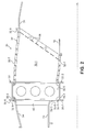
- FIG. 2 is a cross-sectional view of an embodiment of an exhaust case assembly of the gas turbine engine according to the present invention.
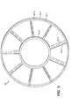
- FIG. 3 is a perspective view of a cold frame of the exhaust case assembly of FIG. 2 .
- FIG. 4 is a front view of a portion of the exhaust case assembly of FIG. 2 .
- FIG. 5 is an aft perspective view of a portion of the exhaust case assembly of FIG. 2 .
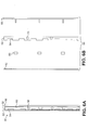
- FIG. 6A is a side view of a cartridge housing assembly of the exhaust case assembly of FIG. 2 .
- FIG. 6B is an exploded side view of the cartridge housing assembly of FIG. 6A .
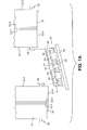
- FIG. 7A is an exploded top view of a portion of the exhaust case assembly of FIG. 2 , shown prior to assembly.
- FIG. 7B is a top view of the portion of the exhaust case assembly of FIG. 7A , shown after completed assembly.
- the present invention provides a flowpath assembly suitable for use in a gas turbine engine, such as in a gas turbine engine exhaust case assembly.
- a plurality of flowpath insert ducts are provided in a cascade configuration, with side walls of adjacent insert ducts located next to one another such that vane structures can be formed where side walls of adjacent flowpath insert ducts meet.
- a leading edge piece and/or a trailing edge piece can be provided at each interface between adjacent insert ducts.
- a cold frame can be provided to provide radial support such that the flowpath insert ducts can "float" relative to the cold frame with the cold frame providing radial support to the engine.
- Each flowpath insert duct can be provided in multiple parts, such as in two halves that are attached together at respective flanges with suitable fasteners.
- cartridge housings can be used to secure adjacent flowpath insert ducts together, using retention hooks and a translating retention plate. Additional features and benefits of the present invention will be appreciated in view of the description that follows and the accompanying figures.
- FIG. 1 is a cross-sectional view of an embodiment of a gas turbine engine 10 that includes a fan section 12, a low pressure compressor (LPC) section 14, a high pressure compressor (HPC) section 16, a combustor section 18, a high pressure turbine (HPT) section 20, a low pressure turbine (LPT) section 22, and a turbine exhaust case (TEC) assembly 24 (sometimes simply referred to as a exhaust case assembly).
- the engine 10 has a two-spool configuration, with spools arranged to rotate about a centerline C L . Because the basic construction and operation of gas turbine engines is well-known to those of ordinary skill in the art, further explanation is unnecessary.
- the present invention is suitable for use with gas turbine engines of nearly any configuration, and the illustrated embodiment is shown merely by way of example and not limitation.
- the illustrated embodiment shows a high bypass ratio engine, while the present invention is equally applicable to low bypass ratio engines as well.
- FIG. 2 is a cross-sectional view of an embodiment of the exhaust case assembly 24, which includes a cold frame 30 and a plurality of flowpath insert ducts 32. As shown in FIG. 2 , the exhaust case assembly 24 is positioned between a first duct 34 and a second duct 36.
- the flowpath insert ducts 32 define interior flowpath volumes for the passage of fluids, which are typically hot exhaust gases.
- the cold frame 30 is positioned outside of the flowpath volumes and therefore typically in a relative cold area of the engine 10.
- FIG. 3 is a perspective view of the cold frame 30, which includes a front frame member (or plate) 30-1, a rear frame member (or plate) 30-2, an outer diameter (OD) ring 30-3, an inner diameter (ID) ring 30-4, and reinforcement members (or gussets) 30-5.
- the front and rear frame members 30-1 and 30-2 each include an OD annular portion 30-6 and an ID annular portion 30-7 with a plurality of circumferentially spaced spokes 30-8 extending radially between the OD and ID annular portions 30-6 and 30-7.
- the OD ring 30-3 and the ID ring 30-4 each extend generally axially between the front and rear frame members 30-1 and 30-2 at the OD annular portions 30-6 and the ID annular portions 30-7, respectively.
- the reinforcement members 30-5 extend between the front and rear frame members 30-1 and 30-2, and the OD and ID rings 30-6 and 30-7.
- the cold frame 30 can be made from suitable metallic materials, or alternatively composites or other desired materials.
- the front and rear frame members 30-1 and 30-2, the reinforcement members 30-5, and the OD and ID rings 30-6 and 30-7, can be cut to shape from sheet using water jet cutting, or other suitable processes. Once cut, the OD and ID rings 30-6 and 30-7 can be rolled to an annular shape and welded.
- the reinforcement members 30-5 can be welded to the front and rear frame members 30-1 and 30-2 and the OD and ID rings 30-6 and 30-7. Openings for weight reduction and clearance can be formed as desired in portions of the cold frame 30, such as in the reinforcement members 30-5.
- FIG. 4 is a front view of a portion of the exhaust case assembly 24 (shown looking aft), and FIG. 5 is an aft perspective view of a portion of the exhaust case assembly 24.
- the flowpath insert ducts 32 are arranged in a cascade configuration, and each insert duct 32 defines an interior flowpath volume through which fluids can pass (shown schematically by arrows in FIG. 5 ). Gaps between adjacent inserts 32 can allow space for the cold frame and/or radially-extending tubes 40 or other components (see FIG. 4 ). These gaps can be arranged outside of an exhaust flowpath of the engine 10 and outside of the interior flowpath volumes of the insert ducts 32.
- Each flowpath insert duct 32 can be made of multiple sub-parts attached together, though in alternative embodiments the inserts 32 can be of a one-piece construction. In the illustrated embodiment, the flowpath insert ducts 32 are of a two-piece construction, with a first part 32A and a second part 32B that are attached together. A multi-part construction has numerous advantages, including increased ease of repair or replacement of damaged components without requiring repair or replacement of an entire insert duct 32.
- the flowpath insert ducts 32 can be made from suitable metallic or composite materials. For metallic materials, stamping, hydro- and bulge-forming and casting can be used to create the parts.
- Each flowpath insert duct 32 includes side walls 32-1 and 32-2, first and second inward wall portions 32-3 and 32-4, first and second outer wall portions 32-5 and 32-6.
- the inner and outer wall portions could be integrally formed along with one or both side walls 32-1 and 32-2 and a single piece, depending on the geometry desired.
- the side wall 32-1, the first inward wall portion 32-3 and the first outward wall portion 32-5 are part of the first part 32A, and generally have a U-shaped configuration.
- the side wall 32-2, the second inward wall portion 32-4 and the second outward wall portion 32-6 are part of the second part 32B, and generally have a U-shaped configuration.
- the first and second parts 32A and 32B can further include substantially axially-extending flanges 32-7 and 32-8, respectively, located at the inward and outward wall portions 32-3, 32-4, 32-5 and 32-6.
- the flanges 32-7 and 32-8 can adjoin each other in a close-fitting relationship and accept suitable fasteners (e.g., rivets, bolts, etc.) to secure the parts 32A and 32B together with the first and second inward wall portions 32-3 and 32-4 adjoining each other to collectively define an inward wall and the first and second outward wall portions 32-5 and 32-6 adjoining each other to collectively define an outward wall.
- Suitable fluidic seals can be formed by abutment of the wall portions 32-3, 32-4, 32-5 and 32-6 at the resultant joints.
- a flowpath volume is defined by each insert duct 32, bounded by the side walls 32-1 and 32-2 and the inward and outward walls (including portions 32-3, 32-4, 32-5 and 32-6).
- the shapes of portions of the insert ducts 32 are illustrated merely by way of example and not limitation. A variety of shapes are possible in further embodiments, as desired for particular applications, such as to provide desired fluidic flow through the flowpath volumes of the insert ducts 32.
- each insert duct 32 can further include flanges 32-9 at the inward and outward walls at both forward and aft ends, to facilitate attachment of the flowpath insert duct 32 to the ducts 34 and 36 with suitable fasteners (see FIG. 2 ).
- Retention hooks 38 can be positioned to extend outward (i.e., circumferentially or tangentially relative to the centerline C L ) along exterior portions of each of the side walls 32-1 and 32-2. As shown in FIG. 2 , the retention hooks 38 on the side wall 32-1 are positioned in a row proximate an aft edge. The retention hooks 38 allow for engagement with corresponding structures to help secure the insert ducts 32, as explained further below.
- a leading edge piece 42 can be positioned at a leading edge of an interface between adjacent flowpath insert ducts 32.
- the leading edge piece 42 can have an aerodynamic contour, such that adjacent side walls of adjacent flowpath insert ducts 32 can act as vanes to straighten or otherwise influence fluid flow through the exhaust case assembly 24.
- FIG. 6A is a side view of a cartridge housing assembly 50 of the exhaust case assembly 24, and FIG. 6B is an exploded side view of the cartridge housing assembly 50.
- the cartridge housing assembly 50 of the illustrated embodiment includes a housing body 52 having a plurality of cutout notches 54 (a total of seven in the illustrated embodiment), threaded members 56, a trailing edge piece 58, retention members 60 (e.g., nuts), and a pair of retention plates 62 (only one visible in FIGS. 6A and 6B , but see FIGS. 7A and 7B ).
- the cartridge housing assembly 50 can further include pin nuts (not shown in FIGS. 6A and 6B ), which are explained further with respect to FIGS. 7A and 7B .
- the cartridge housing assembly 50 helps secure adjacent flowpath insert ducts 32 together.
- the cartridge housing assembly 50 is configured to be positioned at an aft end of the flowpath insert ducts 32, and thus includes the trailing edge piece 58.
- the trailing edge piece 58 can be configured in an aerodynamic configuration, as desired for particular applications.
- the cartridge housing assembly 50 can also be utilized at a leading edge location, with the trailing edge piece 58 replaced by the leading edge piece 42.
- either or both of the leading edge piece 42 and the trailing edge piece 58 can be secured to adjacent flowpath insert ducts 32 in any other suitable manner (e.g., using rivets, bolts, etc.) without the use of the cartridge housing assembly 50.
- FIG. 7A is an exploded top view of a portion of the exhaust case assembly 24, shown prior to assembly
- FIG. 7B is a top view of the portion of the exhaust case assembly 24, shown after completed assembly.
- the cartridge housing assembly 50 is configured such that the trailing edge piece 58 can be fixedly attached to the housing body 52 with the retention members 60, such as with threaded extensions from the trailing edge piece 58.
- the housing body 52 has a plurality of cutout notches 54 defined along both sides of a leading edge. The cutout notches 54 provide openings into which at least a portion of a corresponding retention hook 38 of a given flowpath insert duct 32 can be inserted and engaged.
- the threaded members 56 are rotatably secured to the housing body 52, and can include reverse-threaded portions at either end and an engagement portion for engagement with a rotation tool in a center portion.
- a pair of pin nuts 64 can be threadably engaged with the end portions of each threaded member 56, such that rotation of the threaded member 56 in a first direction can cause the pin nuts 64 to move (i.e., translate) apart and rotation in an opposite, second direction can cause the pin nuts 64 to move (i.e., translate) together.
- One of the retention plates 62 is engaged with each pin nut 64, such that the retention plates 62 each move (i.e., translate) together with the associated pin nuts 64.
- the retention plates are arranged proximate to the cutout notches 54 in the housing body 52. As shown in FIG. 7A , the retention plates 62 can be positioned to allow access to the cutout notches 54 to facilitate insertion of corresponding retention hooks 38 of the flowpath insert ducts 32. After the retention hooks 38 are engaged with the cutout notches 54, the retention plates can be translated by way of rotational adjustment of the threaded members 56 to extend over or into the cutout notches 54 and thereby block an exit path of the retention hooks 38 from the cutout notches 54 and lock the retention hooks 38 relative to the housing body 52. Disengagement of the flowpath insert duct 32 can be achieved simply by reversing the process, by rotating the threaded members 56 and then removing the retention hooks 38 from the cutout notches 54.
- any relative terms or terms of degree used herein such as “substantially”, “approximately”, “essentially”, “generally” and the like, should be interpreted in accordance with and subject to any applicable definitions or limits expressly stated herein. In all instances, any relative terms or terms of degree used herein should be interpreted to broadly encompass any relevant disclosed embodiments as well as such ranges or variations as would be understood by a person of ordinary skill in the art in view of the entirety of the present disclosure, such as to encompass ordinary manufacturing tolerance variations and the like.
Landscapes
- Engineering & Computer Science (AREA)
- Mechanical Engineering (AREA)
- General Engineering & Computer Science (AREA)
- Exhaust Silencers (AREA)
- Supercharger (AREA)
- Turbine Rotor Nozzle Sealing (AREA)
Abstract
Description
- The present invention relates generally to gas turbine engines, and more particularly to flowpath structures for use in gas turbine engines.
- Gas turbine engines typically include an exhaust case located at an aft (or rear) portion of the engine, through which hot fluid is exhausted from the engine. When a temperature delta results in a thermal fight, and/or a complex aero configuration is required, prior art exhaust cases could be undesirably complicated in design and heavy, and could produce too much fluid leakage.
- Therefore, it is desired to provide an improved flowpath structure for a gas turbine engine suitable for use in an exhaust case assembly.
- A flowpath assembly for a gas turbine engine according to the present invention includes a plurality of flowpath insert ducts arranged in a cascade configuration. Each flowpath duct includes a radially inward wall, a radially outward wall, a first side wall, and a second side wall. A flowpath volume is defined between the inward, outward, first side and second side walls. The first side wall of a given one of the plurality of flowpath insert ducts is positioned adjacent to the second sidewall of an adjacent one of the plurality of flowpath insert ducts in the cascade configuration.
Preferred embodiments of the invention will now be described by way of example only and with reference to the accompanying drawings. -
FIG. 1 is a cross-sectional view of an embodiment of a gas turbine engine. -
FIG. 2 is a cross-sectional view of an embodiment of an exhaust case assembly of the gas turbine engine according to the present invention. -
FIG. 3 is a perspective view of a cold frame of the exhaust case assembly ofFIG. 2 . -
FIG. 4 is a front view of a portion of the exhaust case assembly ofFIG. 2 . -
FIG. 5 is an aft perspective view of a portion of the exhaust case assembly ofFIG. 2 . -
FIG. 6A is a side view of a cartridge housing assembly of the exhaust case assembly ofFIG. 2 . -
FIG. 6B is an exploded side view of the cartridge housing assembly ofFIG. 6A . -
FIG. 7A is an exploded top view of a portion of the exhaust case assembly ofFIG. 2 , shown prior to assembly. -
FIG. 7B is a top view of the portion of the exhaust case assembly ofFIG. 7A , shown after completed assembly. - While the above-identified drawing figures set forth an embodiment of the invention, other embodiments are also contemplated, as noted in the discussion. In all cases, this disclosure presents the invention by way of representation and not limitation. It should be understood that numerous other modifications and embodiments can be devised by those skilled in the art, which fall within the scope of the invention as defined by the claims. The figures may not be drawn to scale.
- In general, the present invention provides a flowpath assembly suitable for use in a gas turbine engine, such as in a gas turbine engine exhaust case assembly. A plurality of flowpath insert ducts are provided in a cascade configuration, with side walls of adjacent insert ducts located next to one another such that vane structures can be formed where side walls of adjacent flowpath insert ducts meet. A leading edge piece and/or a trailing edge piece can be provided at each interface between adjacent insert ducts. A cold frame can be provided to provide radial support such that the flowpath insert ducts can "float" relative to the cold frame with the cold frame providing radial support to the engine. Each flowpath insert duct can be provided in multiple parts, such as in two halves that are attached together at respective flanges with suitable fasteners. In some embodiments, cartridge housings can be used to secure adjacent flowpath insert ducts together, using retention hooks and a translating retention plate. Additional features and benefits of the present invention will be appreciated in view of the description that follows and the accompanying figures.
-
FIG. 1 is a cross-sectional view of an embodiment of agas turbine engine 10 that includes afan section 12, a low pressure compressor (LPC)section 14, a high pressure compressor (HPC)section 16, acombustor section 18, a high pressure turbine (HPT)section 20, a low pressure turbine (LPT)section 22, and a turbine exhaust case (TEC) assembly 24 (sometimes simply referred to as a exhaust case assembly). In the illustrated embodiment, theengine 10 has a two-spool configuration, with spools arranged to rotate about a centerline CL. Because the basic construction and operation of gas turbine engines is well-known to those of ordinary skill in the art, further explanation is unnecessary. However, it should be noted that the present invention is suitable for use with gas turbine engines of nearly any configuration, and the illustrated embodiment is shown merely by way of example and not limitation. For example, the illustrated embodiment shows a high bypass ratio engine, while the present invention is equally applicable to low bypass ratio engines as well. -
FIG. 2 is a cross-sectional view of an embodiment of theexhaust case assembly 24, which includes acold frame 30 and a plurality offlowpath insert ducts 32. As shown inFIG. 2 , theexhaust case assembly 24 is positioned between afirst duct 34 and asecond duct 36. Theflowpath insert ducts 32 define interior flowpath volumes for the passage of fluids, which are typically hot exhaust gases. Thecold frame 30 is positioned outside of the flowpath volumes and therefore typically in a relative cold area of theengine 10. -
FIG. 3 is a perspective view of thecold frame 30, which includes a front frame member (or plate) 30-1, a rear frame member (or plate) 30-2, an outer diameter (OD) ring 30-3, an inner diameter (ID) ring 30-4, and reinforcement members (or gussets) 30-5. In the illustrated embodiment, the front and rear frame members 30-1 and 30-2 each include an OD annular portion 30-6 and an ID annular portion 30-7 with a plurality of circumferentially spaced spokes 30-8 extending radially between the OD and ID annular portions 30-6 and 30-7. The OD ring 30-3 and the ID ring 30-4 each extend generally axially between the front and rear frame members 30-1 and 30-2 at the OD annular portions 30-6 and the ID annular portions 30-7, respectively. The reinforcement members 30-5 extend between the front and rear frame members 30-1 and 30-2, and the OD and ID rings 30-6 and 30-7. Thecold frame 30 can be made from suitable metallic materials, or alternatively composites or other desired materials. The front and rear frame members 30-1 and 30-2, the reinforcement members 30-5, and the OD and ID rings 30-6 and 30-7, can be cut to shape from sheet using water jet cutting, or other suitable processes. Once cut, the OD and ID rings 30-6 and 30-7 can be rolled to an annular shape and welded. The reinforcement members 30-5 can be welded to the front and rear frame members 30-1 and 30-2 and the OD and ID rings 30-6 and 30-7. Openings for weight reduction and clearance can be formed as desired in portions of thecold frame 30, such as in the reinforcement members 30-5. -
FIG. 4 is a front view of a portion of the exhaust case assembly 24 (shown looking aft), andFIG. 5 is an aft perspective view of a portion of theexhaust case assembly 24. Theflowpath insert ducts 32 are arranged in a cascade configuration, and eachinsert duct 32 defines an interior flowpath volume through which fluids can pass (shown schematically by arrows inFIG. 5 ). Gaps betweenadjacent inserts 32 can allow space for the cold frame and/or radially-extendingtubes 40 or other components (seeFIG. 4 ). These gaps can be arranged outside of an exhaust flowpath of theengine 10 and outside of the interior flowpath volumes of theinsert ducts 32. - Each
flowpath insert duct 32 can be made of multiple sub-parts attached together, though in alternative embodiments theinserts 32 can be of a one-piece construction. In the illustrated embodiment, theflowpath insert ducts 32 are of a two-piece construction, with afirst part 32A and asecond part 32B that are attached together. A multi-part construction has numerous advantages, including increased ease of repair or replacement of damaged components without requiring repair or replacement of anentire insert duct 32. Theflowpath insert ducts 32 can be made from suitable metallic or composite materials. For metallic materials, stamping, hydro- and bulge-forming and casting can be used to create the parts. - Each flowpath insert
duct 32 includes side walls 32-1 and 32-2, first and second inward wall portions 32-3 and 32-4, first and second outer wall portions 32-5 and 32-6. The inner and outer wall portions could be integrally formed along with one or both side walls 32-1 and 32-2 and a single piece, depending on the geometry desired. The side wall 32-1, the first inward wall portion 32-3 and the first outward wall portion 32-5 are part of thefirst part 32A, and generally have a U-shaped configuration. Likewise, the side wall 32-2, the second inward wall portion 32-4 and the second outward wall portion 32-6 are part of thesecond part 32B, and generally have a U-shaped configuration. The first andsecond parts parts insert duct 32, bounded by the side walls 32-1 and 32-2 and the inward and outward walls (including portions 32-3, 32-4, 32-5 and 32-6). It should be noted that the shapes of portions of theinsert ducts 32 are illustrated merely by way of example and not limitation. A variety of shapes are possible in further embodiments, as desired for particular applications, such as to provide desired fluidic flow through the flowpath volumes of theinsert ducts 32. Theparts insert duct 32 can further include flanges 32-9 at the inward and outward walls at both forward and aft ends, to facilitate attachment of theflowpath insert duct 32 to theducts FIG. 2 ). - Retention hooks 38 can be positioned to extend outward (i.e., circumferentially or tangentially relative to the centerline CL) along exterior portions of each of the side walls 32-1 and 32-2. As shown in
FIG. 2 , the retention hooks 38 on the side wall 32-1 are positioned in a row proximate an aft edge. The retention hooks 38 allow for engagement with corresponding structures to help secure theinsert ducts 32, as explained further below. - A
leading edge piece 42 can be positioned at a leading edge of an interface between adjacentflowpath insert ducts 32. Theleading edge piece 42 can have an aerodynamic contour, such that adjacent side walls of adjacentflowpath insert ducts 32 can act as vanes to straighten or otherwise influence fluid flow through theexhaust case assembly 24. -
FIG. 6A is a side view of acartridge housing assembly 50 of theexhaust case assembly 24, andFIG. 6B is an exploded side view of thecartridge housing assembly 50. Thecartridge housing assembly 50 of the illustrated embodiment includes ahousing body 52 having a plurality of cutout notches 54 (a total of seven in the illustrated embodiment), threadedmembers 56, a trailingedge piece 58, retention members 60 (e.g., nuts), and a pair of retention plates 62 (only one visible inFIGS. 6A and 6B , but seeFIGS. 7A and7B ). Thecartridge housing assembly 50 can further include pin nuts (not shown inFIGS. 6A and 6B ), which are explained further with respect toFIGS. 7A and7B . Thecartridge housing assembly 50 helps secure adjacentflowpath insert ducts 32 together. In the illustrated embodiment, thecartridge housing assembly 50 is configured to be positioned at an aft end of theflowpath insert ducts 32, and thus includes the trailingedge piece 58. The trailingedge piece 58 can be configured in an aerodynamic configuration, as desired for particular applications. However, thecartridge housing assembly 50 can also be utilized at a leading edge location, with the trailingedge piece 58 replaced by the leadingedge piece 42. In alternative embodiments, either or both of theleading edge piece 42 and the trailingedge piece 58 can be secured to adjacentflowpath insert ducts 32 in any other suitable manner (e.g., using rivets, bolts, etc.) without the use of thecartridge housing assembly 50. -
FIG. 7A is an exploded top view of a portion of theexhaust case assembly 24, shown prior to assembly, andFIG. 7B is a top view of the portion of theexhaust case assembly 24, shown after completed assembly. As shown inFIGS. 6A-7B , thecartridge housing assembly 50 is configured such that the trailingedge piece 58 can be fixedly attached to thehousing body 52 with theretention members 60, such as with threaded extensions from the trailingedge piece 58. Thehousing body 52 has a plurality ofcutout notches 54 defined along both sides of a leading edge. Thecutout notches 54 provide openings into which at least a portion of acorresponding retention hook 38 of a givenflowpath insert duct 32 can be inserted and engaged. The threaded members 56 (two a provided in the illustrated embodiment, though greater or fewer can be provided in alternative embodiments) are rotatably secured to thehousing body 52, and can include reverse-threaded portions at either end and an engagement portion for engagement with a rotation tool in a center portion. A pair ofpin nuts 64 can be threadably engaged with the end portions of each threadedmember 56, such that rotation of the threadedmember 56 in a first direction can cause thepin nuts 64 to move (i.e., translate) apart and rotation in an opposite, second direction can cause thepin nuts 64 to move (i.e., translate) together. One of theretention plates 62 is engaged with eachpin nut 64, such that theretention plates 62 each move (i.e., translate) together with the associated pin nuts 64. The retention plates are arranged proximate to thecutout notches 54 in thehousing body 52. As shown inFIG. 7A , theretention plates 62 can be positioned to allow access to thecutout notches 54 to facilitate insertion of corresponding retention hooks 38 of theflowpath insert ducts 32. After the retention hooks 38 are engaged with thecutout notches 54, the retention plates can be translated by way of rotational adjustment of the threadedmembers 56 to extend over or into thecutout notches 54 and thereby block an exit path of the retention hooks 38 from thecutout notches 54 and lock the retention hooks 38 relative to thehousing body 52. Disengagement of theflowpath insert duct 32 can be achieved simply by reversing the process, by rotating the threadedmembers 56 and then removing the retention hooks 38 from thecutout notches 54. - Any relative terms or terms of degree used herein, such as "substantially", "approximately", "essentially", "generally" and the like, should be interpreted in accordance with and subject to any applicable definitions or limits expressly stated herein. In all instances, any relative terms or terms of degree used herein should be interpreted to broadly encompass any relevant disclosed embodiments as well as such ranges or variations as would be understood by a person of ordinary skill in the art in view of the entirety of the present disclosure, such as to encompass ordinary manufacturing tolerance variations and the like.
- While the invention has been described with reference to an exemplary embodiment(s), it will be understood by those skilled in the art that various changes may be made and equivalents may be substituted for elements thereof without departing from the scope of the invention as defined by the claims. In addition, many modifications may be made to adapt a particular situation or material to the teachings of the invention without departing from the scope thereof. For example, although the present invention has been described with respect to an embodiment as an exhaust case assembly, the flowpath structures of the present invention could be readily used for other applications in other portions of a gas turbine engine, such as in a mid-turbine assembly. Therefore, it is intended that the invention not be limited to the particular embodiment(s) disclosed, but that the invention will include all embodiments falling within the scope of the appended claims.
Claims (15)
- A flowpath assembly (24) for a gas turbine engine (10), the assembly comprising:a plurality of flowpath insert ducts (32) arranged in a cascade configuration, each flowpath duct including:a radially inward wall (32-3, 32-4);a radially outward wall (32-5, 32-6);a first side wall (32-1); anda second side wall (32-2), wherein a flowpath volume is defined between the inward, outward, first side and second side walls,wherein the first side wall of a given one of the plurality of flowpath insert ducts is positioned adjacent to the second sidewall of an adjacent one of the plurality of flowpath insert ducts in the cascade configuration.
- The assembly of claim 1, further comprising:a plurality of leading edge pieces (42) positioned at leading edge locations of interfaces between adjacent flowpath ducts; and/ora cold frame (30), wherein the plurality of flowpath ducts extend through the cold frame, and therein the cold frame extends through at least one gap between a pair of the plurality of flowpath insert ducts, the gap defined outside of the flowpath volumes.
- The assembly of claim 1 or 2, wherein each flowpath duct comprises a first part and a second part attached together, the first part including the first side wall, a first portion of the inward wall and a first portion of the outward wall, the second part including the second side wall, a second portion of the inward wall and a second portion of the outward wall.
- The assembly of claim 3, further comprising:flanges (32-7, 32-8) on opposed portions of the first and second parts of each flowpath duct for securing the first part and the second part together with fasteners.
- The assembly of any of claims 1 to 4, further comprising:a plurality of outward-facing retention hooks (38) located on each of the first and second side walls of each of the flowpath ducts; anda plurality of housing cartridges (50) configured to engage the opposed retention hooks of adjacent flowpath ducts to provide engagement therebetween.
- The assembly of claim 5, wherein each housing cartridge comprises:a body (52);a plurality of cutout notches (54) defined in the body configured to accept the retention hooks of flowpath ducts;a threaded member (56);a movable member (64) threadably engaged with the threaded member;a retention plate (62) engaged with the movable member and positioned proximate a row of the plurality of cutout notches, wherein rotation of the threaded member produces translational movement of the movable member and the retention plate such that retention hooks of at least one of the flowpath ducts can be removably retained in the cutout notches by the retention plate.
- The assembly of claim 5 or 6, further comprising:a trailing edge piece (58) attached to each housing cartridge and configured to extend between adjacent flowpath ducts.
- The assembly of any of claims 1 to 7, further comprising:forward and aft flanges (32-9) on each of the flowpath ducts from attachment to adjacent gas turbine engine components.
- A method of making a flowpath assembly for a gas turbine engine (10), the method comprising:providing a plurality of flowpath inserts (32) that each define a perimeter boundary of a flowpath volume;positioning the flowpath inserts in a cascade arrangement at a cold frame (30);positioning a leading edge member (42) at each leading edge interface between adjacent flowpath inserts;engaging a cartridge housing (50) between each adjacent pair of the flowpath inserts.
- The method of claim 9, wherein the step of engaging the cartridge housing comprises:inserting retention hooks (38) of the flowpath inserts into cutout notches (54) of an associated one of the cartridge housings; andmoving a retention plate (62) into a position to retain the retention hooks in the cutout notches.
- The method of claim 9 or 10, further comprising:water-jet cutting a pair of cold frame members each defining a plurality of support spokes (30-8);making a plurality of reinforcement members (30-5);rolling an inner ring (30-4) and an outer ring (30-3);welding the pair of cold frame members to the inner and outer rings; andwelding the reinforcement members between support spokes of the pair of cold frame members.
- The method of claim 9, 10 or 11, further comprising:assembling each flowpath duct by securing a first part (32A) and a second part (32B) together with fasteners.
- A flowpath insert member (32) for a gas turbine engine (10), the member comprising:a first part (32A) that includes a first side wall (32-1), a first portion of an inward wall (32-3), a first portion of an outward wall (32-5), and at least one substantially axially-extending first connection flange (32-7); anda second part (32B) including a second side wall (32-2), a second portion of the inward wall (32-4), a second portion of the outward wall (32-6), and at least one substantially axially-extending second connection flange (32-8),wherein the first part and the second part at attached together with fasteners secured to the first and second connection flanges such that the first and second portions of the inward wall adjoin each other and the first and second portions of the outward wall adjoin each other, and wherein a flowpath volume is defined between the inward, outward, first side and second side walls.
- The flowpath insert member of claim 13, further comprising:a plurality of outward-facing retention hooks (32) located on each of the first and second side walls.
- A member (32A, 32B) for a flowpath insert (32) of a gas turbine engine (10), the member comprising:a side wall (32-1,32-2);an inward wall segment (32-3, 32-4) extending from the side wall;an outward wall segment (32-5, 32-6) extending from the side wall, wherein the side wall, the inward wall segment and the outward wall segment define a substantially U-shaped configuration;a substantially axially-extending connection flange (32-7, 32-8) having openings for fastener attachment, the connection flange located on one of the inward wall segment and the outward wall segment; anda plurality of outward-facing retention hooks (38) located on the side wall.
Applications Claiming Priority (1)
| Application Number | Priority Date | Filing Date | Title |
|---|---|---|---|
| US13/172,128 US8894365B2 (en) | 2011-06-29 | 2011-06-29 | Flowpath insert and assembly |
Publications (3)
| Publication Number | Publication Date |
|---|---|
| EP2540982A2 true EP2540982A2 (en) | 2013-01-02 |
| EP2540982A3 EP2540982A3 (en) | 2018-01-03 |
| EP2540982B1 EP2540982B1 (en) | 2020-01-08 |
Family
ID=46084836
Family Applications (1)
| Application Number | Title | Priority Date | Filing Date |
|---|---|---|---|
| EP12166087.2A Active EP2540982B1 (en) | 2011-06-29 | 2012-04-27 | Flowpath insert and assembly |
Country Status (2)
| Country | Link |
|---|---|
| US (1) | US8894365B2 (en) |
| EP (1) | EP2540982B1 (en) |
Families Citing this family (1)
| Publication number | Priority date | Publication date | Assignee | Title |
|---|---|---|---|---|
| US10443415B2 (en) | 2016-03-30 | 2019-10-15 | General Electric Company | Flowpath assembly for a gas turbine engine |
Family Cites Families (19)
| Publication number | Priority date | Publication date | Assignee | Title |
|---|---|---|---|---|
| US3369366A (en) | 1964-05-28 | 1968-02-20 | Gen Electric | Jet engine support structure |
| US4827588A (en) * | 1988-01-04 | 1989-05-09 | Williams International Corporation | Method of making a turbine nozzle |
| US4993918A (en) * | 1989-05-19 | 1991-02-19 | United Technologies Corporation | Replaceable fairing for a turbine exhaust case |
| US5080555A (en) | 1990-11-16 | 1992-01-14 | General Motors Corporation | Turbine support for gas turbine engine |
| US5483792A (en) * | 1993-05-05 | 1996-01-16 | General Electric Company | Turbine frame stiffening rails |
| US5609467A (en) | 1995-09-28 | 1997-03-11 | Cooper Cameron Corporation | Floating interturbine duct assembly for high temperature power turbine |
| DE69824925T2 (en) * | 1997-09-17 | 2005-08-25 | Mitsubishi Heavy Industries, Ltd. | Leitschaufelpaar |
| US6123506A (en) * | 1999-01-20 | 2000-09-26 | Pratt & Whitney Canada Corp. | Diffuser pipe assembly |
| ES2243358T3 (en) * | 2001-04-04 | 2005-12-01 | Siemens Aktiengesellschaft | TURBINE AND TABBINE ALABE. |
| US6543996B2 (en) | 2001-06-28 | 2003-04-08 | General Electric Company | Hybrid turbine nozzle |
| US7200933B2 (en) * | 2002-08-14 | 2007-04-10 | Volvo Aero Corporation | Method for manufacturing a stator component |
| US7195456B2 (en) * | 2004-12-21 | 2007-03-27 | United Technologies Corporation | Turbine engine guide vane and arrays thereof |
| EP1975373A1 (en) | 2007-03-06 | 2008-10-01 | Siemens Aktiengesellschaft | Guide vane duct element for a guide vane assembly of a gas turbine engine |
| US8371812B2 (en) | 2008-11-29 | 2013-02-12 | General Electric Company | Turbine frame assembly and method for a gas turbine engine |
| US8177488B2 (en) | 2008-11-29 | 2012-05-15 | General Electric Company | Integrated service tube and impingement baffle for a gas turbine engine |
| US8152451B2 (en) | 2008-11-29 | 2012-04-10 | General Electric Company | Split fairing for a gas turbine engine |
| US8371810B2 (en) * | 2009-03-26 | 2013-02-12 | General Electric Company | Duct member based nozzle for turbine |
| WO2011047693A1 (en) | 2009-10-19 | 2011-04-28 | Siemens Aktiengesellschaft | Nozzle guide vane arrangement and turbine engine |
| JP5946543B2 (en) * | 2011-12-23 | 2016-07-06 | ゲーコーエヌ エアロスペース スウェーデン アーベー | Gas turbine engine support structure |
-
2011
- 2011-06-29 US US13/172,128 patent/US8894365B2/en not_active Expired - Fee Related
-
2012
- 2012-04-27 EP EP12166087.2A patent/EP2540982B1/en active Active
Non-Patent Citations (1)
| Title |
|---|
| None |
Also Published As
| Publication number | Publication date |
|---|---|
| EP2540982A3 (en) | 2018-01-03 |
| EP2540982B1 (en) | 2020-01-08 |
| US20130000769A1 (en) | 2013-01-03 |
| US8894365B2 (en) | 2014-11-25 |
Similar Documents
| Publication | Publication Date | Title |
|---|---|---|
| JP4513000B2 (en) | Method and apparatus for assembling a gas turbine engine | |
| US10180084B2 (en) | Structural case for aircraft gas turbine engine | |
| EP2093383B1 (en) | Vane and vane assembly | |
| EP2971579B1 (en) | Aft fairing sub-assembly for turbine exhaust case fairing | |
| US8602726B2 (en) | Sectored distributor for turbomachine | |
| EP3170981B1 (en) | An airfoil comprising a baffle, a gas turbine engine, and a method of repairing an airfoil | |
| DE112009003550T5 (en) | Integrated supply pipe and baffle for a gas turbine engine | |
| EP3034804B1 (en) | Pre-diffuser strut for gas turbine engine | |
| CA2513079A1 (en) | Lightweight annular interturbine duct | |
| JP6730031B2 (en) | Fixing jig and method for mounting turbine blades | |
| US10196933B2 (en) | Tripod buckle for split fairing of a gas turbine engine | |
| CN110454234A (en) | The interlocking grade of airfoil | |
| EP3557002B1 (en) | Platform for an airfoil of a gas turbine engine | |
| EP3232009B1 (en) | Blade outer air seal having retention snap ring | |
| EP2540982B1 (en) | Flowpath insert and assembly | |
| EP3263841A2 (en) | Turbine case boss | |
| EP2404037B1 (en) | Integrally bladed rotor for a turbomachine | |
| EP3040523B1 (en) | Integrated seal supports | |
| JP6002325B2 (en) | Buckle joint for split fairing of gas turbine engine | |
| EP3222821B1 (en) | Anti-rotation shim seal | |
| EP4650568A2 (en) | Additively manufactured turbine vane cluster | |
| EP2722485B1 (en) | Inner ring for a stator assembly with adjustable vanes |
Legal Events
| Date | Code | Title | Description |
|---|---|---|---|
| PUAI | Public reference made under article 153(3) epc to a published international application that has entered the european phase |
Free format text: ORIGINAL CODE: 0009012 |
|
| AK | Designated contracting states |
Kind code of ref document: A2 Designated state(s): AL AT BE BG CH CY CZ DE DK EE ES FI FR GB GR HR HU IE IS IT LI LT LU LV MC MK MT NL NO PL PT RO RS SE SI SK SM TR |
|
| AX | Request for extension of the european patent |
Extension state: BA ME |
|
| RAP1 | Party data changed (applicant data changed or rights of an application transferred) |
Owner name: UNITED TECHNOLOGIES CORPORATION |
|
| PUAL | Search report despatched |
Free format text: ORIGINAL CODE: 0009013 |
|
| AK | Designated contracting states |
Kind code of ref document: A3 Designated state(s): AL AT BE BG CH CY CZ DE DK EE ES FI FR GB GR HR HU IE IS IT LI LT LU LV MC MK MT NL NO PL PT RO RS SE SI SK SM TR |
|
| AX | Request for extension of the european patent |
Extension state: BA ME |
|
| RIC1 | Information provided on ipc code assigned before grant |
Ipc: B23P 15/04 20060101ALI20171129BHEP Ipc: F01D 5/14 20060101ALN20171129BHEP Ipc: F01D 25/16 20060101ALI20171129BHEP Ipc: F01D 9/04 20060101AFI20171129BHEP Ipc: F01D 9/06 20060101ALN20171129BHEP |
|
| STAA | Information on the status of an ep patent application or granted ep patent |
Free format text: STATUS: REQUEST FOR EXAMINATION WAS MADE |
|
| 17P | Request for examination filed |
Effective date: 20180703 |
|
| RBV | Designated contracting states (corrected) |
Designated state(s): AL AT BE BG CH CY CZ DE DK EE ES FI FR GB GR HR HU IE IS IT LI LT LU LV MC MK MT NL NO PL PT RO RS SE SI SK SM TR |
|
| STAA | Information on the status of an ep patent application or granted ep patent |
Free format text: STATUS: EXAMINATION IS IN PROGRESS |
|
| 17Q | First examination report despatched |
Effective date: 20190314 |
|
| GRAP | Despatch of communication of intention to grant a patent |
Free format text: ORIGINAL CODE: EPIDOSNIGR1 |
|
| STAA | Information on the status of an ep patent application or granted ep patent |
Free format text: STATUS: GRANT OF PATENT IS INTENDED |
|
| RIC1 | Information provided on ipc code assigned before grant |
Ipc: F01D 9/06 20060101ALN20190709BHEP Ipc: F01D 9/04 20060101AFI20190709BHEP Ipc: F01D 5/14 20060101ALN20190709BHEP Ipc: F01D 25/16 20060101ALI20190709BHEP Ipc: B23P 15/04 20060101ALI20190709BHEP |
|
| INTG | Intention to grant announced |
Effective date: 20190801 |
|
| RIN1 | Information on inventor provided before grant (corrected) |
Inventor name: SMITH, DARREN M. |
|
| GRAS | Grant fee paid |
Free format text: ORIGINAL CODE: EPIDOSNIGR3 |
|
| GRAA | (expected) grant |
Free format text: ORIGINAL CODE: 0009210 |
|
| STAA | Information on the status of an ep patent application or granted ep patent |
Free format text: STATUS: THE PATENT HAS BEEN GRANTED |
|
| AK | Designated contracting states |
Kind code of ref document: B1 Designated state(s): AL AT BE BG CH CY CZ DE DK EE ES FI FR GB GR HR HU IE IS IT LI LT LU LV MC MK MT NL NO PL PT RO RS SE SI SK SM TR |
|
| REG | Reference to a national code |
Ref country code: GB Ref legal event code: FG4D |
|
| REG | Reference to a national code |
Ref country code: CH Ref legal event code: EP |
|
| REG | Reference to a national code |
Ref country code: IE Ref legal event code: FG4D |
|
| REG | Reference to a national code |
Ref country code: DE Ref legal event code: R096 Ref document number: 602012067042 Country of ref document: DE |
|
| REG | Reference to a national code |
Ref country code: AT Ref legal event code: REF Ref document number: 1222969 Country of ref document: AT Kind code of ref document: T Effective date: 20200215 |
|
| REG | Reference to a national code |
Ref country code: NL Ref legal event code: MP Effective date: 20200108 |
|
| REG | Reference to a national code |
Ref country code: LT Ref legal event code: MG4D |
|
| PG25 | Lapsed in a contracting state [announced via postgrant information from national office to epo] |
Ref country code: PT Free format text: LAPSE BECAUSE OF FAILURE TO SUBMIT A TRANSLATION OF THE DESCRIPTION OR TO PAY THE FEE WITHIN THE PRESCRIBED TIME-LIMIT Effective date: 20200531 Ref country code: RS Free format text: LAPSE BECAUSE OF FAILURE TO SUBMIT A TRANSLATION OF THE DESCRIPTION OR TO PAY THE FEE WITHIN THE PRESCRIBED TIME-LIMIT Effective date: 20200108 Ref country code: NO Free format text: LAPSE BECAUSE OF FAILURE TO SUBMIT A TRANSLATION OF THE DESCRIPTION OR TO PAY THE FEE WITHIN THE PRESCRIBED TIME-LIMIT Effective date: 20200408 Ref country code: FI Free format text: LAPSE BECAUSE OF FAILURE TO SUBMIT A TRANSLATION OF THE DESCRIPTION OR TO PAY THE FEE WITHIN THE PRESCRIBED TIME-LIMIT Effective date: 20200108 Ref country code: NL Free format text: LAPSE BECAUSE OF FAILURE TO SUBMIT A TRANSLATION OF THE DESCRIPTION OR TO PAY THE FEE WITHIN THE PRESCRIBED TIME-LIMIT Effective date: 20200108 Ref country code: LT Free format text: LAPSE BECAUSE OF FAILURE TO SUBMIT A TRANSLATION OF THE DESCRIPTION OR TO PAY THE FEE WITHIN THE PRESCRIBED TIME-LIMIT Effective date: 20200108 |
|
| PG25 | Lapsed in a contracting state [announced via postgrant information from national office to epo] |
Ref country code: SE Free format text: LAPSE BECAUSE OF FAILURE TO SUBMIT A TRANSLATION OF THE DESCRIPTION OR TO PAY THE FEE WITHIN THE PRESCRIBED TIME-LIMIT Effective date: 20200108 Ref country code: LV Free format text: LAPSE BECAUSE OF FAILURE TO SUBMIT A TRANSLATION OF THE DESCRIPTION OR TO PAY THE FEE WITHIN THE PRESCRIBED TIME-LIMIT Effective date: 20200108 Ref country code: IS Free format text: LAPSE BECAUSE OF FAILURE TO SUBMIT A TRANSLATION OF THE DESCRIPTION OR TO PAY THE FEE WITHIN THE PRESCRIBED TIME-LIMIT Effective date: 20200508 Ref country code: BG Free format text: LAPSE BECAUSE OF FAILURE TO SUBMIT A TRANSLATION OF THE DESCRIPTION OR TO PAY THE FEE WITHIN THE PRESCRIBED TIME-LIMIT Effective date: 20200408 Ref country code: HR Free format text: LAPSE BECAUSE OF FAILURE TO SUBMIT A TRANSLATION OF THE DESCRIPTION OR TO PAY THE FEE WITHIN THE PRESCRIBED TIME-LIMIT Effective date: 20200108 Ref country code: GR Free format text: LAPSE BECAUSE OF FAILURE TO SUBMIT A TRANSLATION OF THE DESCRIPTION OR TO PAY THE FEE WITHIN THE PRESCRIBED TIME-LIMIT Effective date: 20200409 |
|
| REG | Reference to a national code |
Ref country code: DE Ref legal event code: R097 Ref document number: 602012067042 Country of ref document: DE |
|
| PG25 | Lapsed in a contracting state [announced via postgrant information from national office to epo] |
Ref country code: EE Free format text: LAPSE BECAUSE OF FAILURE TO SUBMIT A TRANSLATION OF THE DESCRIPTION OR TO PAY THE FEE WITHIN THE PRESCRIBED TIME-LIMIT Effective date: 20200108 Ref country code: SM Free format text: LAPSE BECAUSE OF FAILURE TO SUBMIT A TRANSLATION OF THE DESCRIPTION OR TO PAY THE FEE WITHIN THE PRESCRIBED TIME-LIMIT Effective date: 20200108 Ref country code: DK Free format text: LAPSE BECAUSE OF FAILURE TO SUBMIT A TRANSLATION OF THE DESCRIPTION OR TO PAY THE FEE WITHIN THE PRESCRIBED TIME-LIMIT Effective date: 20200108 Ref country code: SK Free format text: LAPSE BECAUSE OF FAILURE TO SUBMIT A TRANSLATION OF THE DESCRIPTION OR TO PAY THE FEE WITHIN THE PRESCRIBED TIME-LIMIT Effective date: 20200108 Ref country code: ES Free format text: LAPSE BECAUSE OF FAILURE TO SUBMIT A TRANSLATION OF THE DESCRIPTION OR TO PAY THE FEE WITHIN THE PRESCRIBED TIME-LIMIT Effective date: 20200108 Ref country code: CZ Free format text: LAPSE BECAUSE OF FAILURE TO SUBMIT A TRANSLATION OF THE DESCRIPTION OR TO PAY THE FEE WITHIN THE PRESCRIBED TIME-LIMIT Effective date: 20200108 Ref country code: RO Free format text: LAPSE BECAUSE OF FAILURE TO SUBMIT A TRANSLATION OF THE DESCRIPTION OR TO PAY THE FEE WITHIN THE PRESCRIBED TIME-LIMIT Effective date: 20200108 |
|
| PLBE | No opposition filed within time limit |
Free format text: ORIGINAL CODE: 0009261 |
|
| STAA | Information on the status of an ep patent application or granted ep patent |
Free format text: STATUS: NO OPPOSITION FILED WITHIN TIME LIMIT |
|
| REG | Reference to a national code |
Ref country code: AT Ref legal event code: MK05 Ref document number: 1222969 Country of ref document: AT Kind code of ref document: T Effective date: 20200108 |
|
| PG25 | Lapsed in a contracting state [announced via postgrant information from national office to epo] |
Ref country code: MC Free format text: LAPSE BECAUSE OF FAILURE TO SUBMIT A TRANSLATION OF THE DESCRIPTION OR TO PAY THE FEE WITHIN THE PRESCRIBED TIME-LIMIT Effective date: 20200108 |
|
| REG | Reference to a national code |
Ref country code: CH Ref legal event code: PL |
|
| 26N | No opposition filed |
Effective date: 20201009 |
|
| PG25 | Lapsed in a contracting state [announced via postgrant information from national office to epo] |
Ref country code: LU Free format text: LAPSE BECAUSE OF NON-PAYMENT OF DUE FEES Effective date: 20200427 Ref country code: IT Free format text: LAPSE BECAUSE OF FAILURE TO SUBMIT A TRANSLATION OF THE DESCRIPTION OR TO PAY THE FEE WITHIN THE PRESCRIBED TIME-LIMIT Effective date: 20200108 Ref country code: LI Free format text: LAPSE BECAUSE OF NON-PAYMENT OF DUE FEES Effective date: 20200430 Ref country code: CH Free format text: LAPSE BECAUSE OF NON-PAYMENT OF DUE FEES Effective date: 20200430 Ref country code: AT Free format text: LAPSE BECAUSE OF FAILURE TO SUBMIT A TRANSLATION OF THE DESCRIPTION OR TO PAY THE FEE WITHIN THE PRESCRIBED TIME-LIMIT Effective date: 20200108 |
|
| REG | Reference to a national code |
Ref country code: BE Ref legal event code: MM Effective date: 20200430 |
|
| PG25 | Lapsed in a contracting state [announced via postgrant information from national office to epo] |
Ref country code: SI Free format text: LAPSE BECAUSE OF FAILURE TO SUBMIT A TRANSLATION OF THE DESCRIPTION OR TO PAY THE FEE WITHIN THE PRESCRIBED TIME-LIMIT Effective date: 20200108 Ref country code: PL Free format text: LAPSE BECAUSE OF FAILURE TO SUBMIT A TRANSLATION OF THE DESCRIPTION OR TO PAY THE FEE WITHIN THE PRESCRIBED TIME-LIMIT Effective date: 20200108 Ref country code: BE Free format text: LAPSE BECAUSE OF NON-PAYMENT OF DUE FEES Effective date: 20200430 |
|
| PG25 | Lapsed in a contracting state [announced via postgrant information from national office to epo] |
Ref country code: IE Free format text: LAPSE BECAUSE OF NON-PAYMENT OF DUE FEES Effective date: 20200427 |
|
| PG25 | Lapsed in a contracting state [announced via postgrant information from national office to epo] |
Ref country code: TR Free format text: LAPSE BECAUSE OF FAILURE TO SUBMIT A TRANSLATION OF THE DESCRIPTION OR TO PAY THE FEE WITHIN THE PRESCRIBED TIME-LIMIT Effective date: 20200108 Ref country code: MT Free format text: LAPSE BECAUSE OF FAILURE TO SUBMIT A TRANSLATION OF THE DESCRIPTION OR TO PAY THE FEE WITHIN THE PRESCRIBED TIME-LIMIT Effective date: 20200108 Ref country code: CY Free format text: LAPSE BECAUSE OF FAILURE TO SUBMIT A TRANSLATION OF THE DESCRIPTION OR TO PAY THE FEE WITHIN THE PRESCRIBED TIME-LIMIT Effective date: 20200108 |
|
| PG25 | Lapsed in a contracting state [announced via postgrant information from national office to epo] |
Ref country code: MK Free format text: LAPSE BECAUSE OF FAILURE TO SUBMIT A TRANSLATION OF THE DESCRIPTION OR TO PAY THE FEE WITHIN THE PRESCRIBED TIME-LIMIT Effective date: 20200108 Ref country code: AL Free format text: LAPSE BECAUSE OF FAILURE TO SUBMIT A TRANSLATION OF THE DESCRIPTION OR TO PAY THE FEE WITHIN THE PRESCRIBED TIME-LIMIT Effective date: 20200108 |
|
| REG | Reference to a national code |
Ref country code: DE Ref legal event code: R081 Ref document number: 602012067042 Country of ref document: DE Owner name: RAYTHEON TECHNOLOGIES CORPORATION (N.D.GES.D.S, US Free format text: FORMER OWNER: UNITED TECHNOLOGIES CORPORATION, FARMINGTON, CONN., US Ref country code: DE Ref legal event code: R081 Ref document number: 602012067042 Country of ref document: DE Owner name: RTX CORPORATION (N.D.GES.D. STAATES DELAWARE),, US Free format text: FORMER OWNER: UNITED TECHNOLOGIES CORPORATION, FARMINGTON, CONN., US |
|
| P01 | Opt-out of the competence of the unified patent court (upc) registered |
Effective date: 20230520 |
|
| PGFP | Annual fee paid to national office [announced via postgrant information from national office to epo] |
Ref country code: DE Payment date: 20250319 Year of fee payment: 14 |
|
| REG | Reference to a national code |
Ref country code: DE Ref legal event code: R081 Ref document number: 602012067042 Country of ref document: DE Owner name: RTX CORPORATION (N.D.GES.D. STAATES DELAWARE),, US Free format text: FORMER OWNER: RAYTHEON TECHNOLOGIES CORPORATION (N.D.GES.D.STAATES DELAWARE), ARLINGTON, VA, US |
|
| PGFP | Annual fee paid to national office [announced via postgrant information from national office to epo] |
Ref country code: GB Payment date: 20260319 Year of fee payment: 15 |
|
| PGFP | Annual fee paid to national office [announced via postgrant information from national office to epo] |
Ref country code: FR Payment date: 20260319 Year of fee payment: 15 |