EP2540972A1 - Blade for a gas turbine and method for producing such a blade - Google Patents
Blade for a gas turbine and method for producing such a blade Download PDFInfo
- Publication number
- EP2540972A1 EP2540972A1 EP12173501A EP12173501A EP2540972A1 EP 2540972 A1 EP2540972 A1 EP 2540972A1 EP 12173501 A EP12173501 A EP 12173501A EP 12173501 A EP12173501 A EP 12173501A EP 2540972 A1 EP2540972 A1 EP 2540972A1
- Authority
- EP
- European Patent Office
- Prior art keywords
- blade
- cooling
- radial passage
- film
- wall
- Prior art date
- Legal status (The legal status is an assumption and is not a legal conclusion. Google has not performed a legal analysis and makes no representation as to the accuracy of the status listed.)
- Granted
Links
Images


Classifications
-
- F—MECHANICAL ENGINEERING; LIGHTING; HEATING; WEAPONS; BLASTING
- F01—MACHINES OR ENGINES IN GENERAL; ENGINE PLANTS IN GENERAL; STEAM ENGINES
- F01D—NON-POSITIVE DISPLACEMENT MACHINES OR ENGINES, e.g. STEAM TURBINES
- F01D5/00—Blades; Blade-carrying members; Heating, heat-insulating, cooling or antivibration means on the blades or the members
- F01D5/12—Blades
- F01D5/14—Form or construction
- F01D5/18—Hollow blades, i.e. blades with cooling or heating channels or cavities; Heating, heat-insulating or cooling means on blades
- F01D5/186—Film cooling
-
- F—MECHANICAL ENGINEERING; LIGHTING; HEATING; WEAPONS; BLASTING
- F01—MACHINES OR ENGINES IN GENERAL; ENGINE PLANTS IN GENERAL; STEAM ENGINES
- F01D—NON-POSITIVE DISPLACEMENT MACHINES OR ENGINES, e.g. STEAM TURBINES
- F01D5/00—Blades; Blade-carrying members; Heating, heat-insulating, cooling or antivibration means on the blades or the members
- F01D5/12—Blades
- F01D5/14—Form or construction
- F01D5/18—Hollow blades, i.e. blades with cooling or heating channels or cavities; Heating, heat-insulating or cooling means on blades
- F01D5/187—Convection cooling
-
- F—MECHANICAL ENGINEERING; LIGHTING; HEATING; WEAPONS; BLASTING
- F05—INDEXING SCHEMES RELATING TO ENGINES OR PUMPS IN VARIOUS SUBCLASSES OF CLASSES F01-F04
- F05D—INDEXING SCHEME FOR ASPECTS RELATING TO NON-POSITIVE-DISPLACEMENT MACHINES OR ENGINES, GAS-TURBINES OR JET-PROPULSION PLANTS
- F05D2260/00—Function
- F05D2260/20—Heat transfer, e.g. cooling
- F05D2260/202—Heat transfer, e.g. cooling by film cooling
-
- F—MECHANICAL ENGINEERING; LIGHTING; HEATING; WEAPONS; BLASTING
- F05—INDEXING SCHEMES RELATING TO ENGINES OR PUMPS IN VARIOUS SUBCLASSES OF CLASSES F01-F04
- F05D—INDEXING SCHEME FOR ASPECTS RELATING TO NON-POSITIVE-DISPLACEMENT MACHINES OR ENGINES, GAS-TURBINES OR JET-PROPULSION PLANTS
- F05D2260/00—Function
- F05D2260/20—Heat transfer, e.g. cooling
- F05D2260/221—Improvement of heat transfer
- F05D2260/2214—Improvement of heat transfer by increasing the heat transfer surface
- F05D2260/22141—Improvement of heat transfer by increasing the heat transfer surface using fins or ribs
-
- Y—GENERAL TAGGING OF NEW TECHNOLOGICAL DEVELOPMENTS; GENERAL TAGGING OF CROSS-SECTIONAL TECHNOLOGIES SPANNING OVER SEVERAL SECTIONS OF THE IPC; TECHNICAL SUBJECTS COVERED BY FORMER USPC CROSS-REFERENCE ART COLLECTIONS [XRACs] AND DIGESTS
- Y10—TECHNICAL SUBJECTS COVERED BY FORMER USPC
- Y10T—TECHNICAL SUBJECTS COVERED BY FORMER US CLASSIFICATION
- Y10T29/00—Metal working
- Y10T29/49—Method of mechanical manufacture
- Y10T29/49316—Impeller making
- Y10T29/49336—Blade making
- Y10T29/49339—Hollow blade
- Y10T29/49341—Hollow blade with cooling passage
Definitions
- the present invention relates to the field of gas turbine technology. It refers to a blade for a gas turbine according to the preamble of claim 1. It also refers to a method for producing such a blade.
- the hot gas temperatures which are becoming ever higher, in gas turbines make it necessary to not only produce the rotor blades and/or stator blades in use from special materials but also to cool said blades in an efficient manner using a cooling medium.
- the cooling medium is introduced into the interior of the blades, flows through cooling passages which are arranged in the walls, and discharges to the outside through film-cooling holes in order to form a cooling film on the outer side of the blade at the places which are thermally particularly loaded.
- Cooling passages in the walls are used there in combination with impingement cooling, turbulence-generating elements, backflow and film cooling in order to keep the wall temperatures down so that a satisfactory service life of the components is achieved.
- the invention is based on a blade for a gas turbine, which comprises a blade airfoil, the blade wall of which encloses an interior space, wherein, for cooling the blade wall, provision is made in said blade wall for a cooling arrangement which has a radial passage extending in the longitudinal direction of the blade and from which a multiplicity of cooling passages, extending in the blade wall, branch in the transverse direction, and from which a multiplicity of film-cooling holes are led to the outside in the transverse direction.
- the blade is distinguished by the fact that the distribution of the film-cooling holes along the radial passage is selected independently of the distribution of the cooling passages along the radial passage.
- One development of the invention is characterized in that the radial passage is arranged in an offset manner towards the inside from the middle of the blade wall in order to enable a fan-like arrangement of the film-cooling holes.
- the wall region between the radial passage and the outer side is considerably thicker so that there is adequate wall material for the fan-like arrangement.
- radial passage is accessible from the outside at one end and is sealed off there by means of a subsequently attached sealing element. This access from the outside makes it possible to insert a strip into the interior of the radial passage for protection of the inner walls when the blade is being machined.
- a further development is characterized in that the blade comprises a platform into which the blade airfoil merges at the lower end, and in that the radial passage is accessible from the outside at the transition between the blade airfoil and the platform. In this way, the sealable access lies in the inside of the blade.
- the blade comprises a platform into which the blade airfoil merges at the lower end, forming a fillet, and in that cooling passages are provided in the region of the fillet for cooling the transition region.
- turbulence elements especially in the form of ribs or pins, are provided in the cooling passages for improving the cooling.
- a further development is characterized in that provision is made for impingement cooling holes which lead from the interior space of the blade to the cooling passages.
- cooling passages extend from the radial passage only on one side.
- cooling passages extend from the radial passage on both sides.
- the method according to the invention for producing a blade with a radial passage which is accessible from the outside is characterized in that in a first step, the blade is provided with a radial passage which is open on one side, in that in a second step, a strip-like insert is inserted into the open radial passage, in that in a third step, film-cooling holes are introduced into the blade from the outside, wherein the wall of the radial passage opposite the film-cooling holes is protected by means of the insert during the machining, and in that in a fourth step, the insert is removed from the radial passage.
- One development of the method according to the invention is characterized in that the radial passage is sealed off with a sealing element after removing the insert.
- the sealing element is hard-soldered.
- Another development of the method according to the invention is distinguished by the fact that the film-cooling holes are introduced by laser drilling, and in that a PTFE strip is used as the insert.
- the present invention deals with a blade for a gas turbine, as is shown by way of example in Fig. 1 in a perspective side view.
- the blade 10 which can be a rotor blade or a stator blade of the gas turbine, comprises a blade airfoil 11 which, as is customary, has a leading edge 13, a trailing edge 14, a pressure side 15 and a suction side 16.
- the blade airfoil 11 has a blade wall 18 which encloses a hollow interior space 17.
- a cooling arrangement 19 (shown by dashed lines) is accommodated in the blade wall 18 and directs a cooling medium, e.g. cooling air, coming from the inside, through the wall and then guides the cooling medium to the outside for forming a cooling film.
- the cooling arrangement 19 in this example comprises a central radial passage 20 from which cooling passages 21, 22 project equidistantly and on both sides. Furthermore, extending outwards from the radial passage 20 are film-cooling holes 23 through which the cooling medium discharges to the outside for forming a film. With this type of cooling arrangement, it is now essential for the invention that the distribution or density or periodicity of the film-cooling holes 23 is selected independently of the distribution or density or periodicity of the cooling passages 21, 22 in order to optimize the film cooling on the outer side of the blade 10 independently of the internal wall cooling.
- FIG. 2 an exemplary embodiment of a cooling arrangement according to the invention is reproduced in cross section ( Fig. 2a ) and in side view ( Fig. 2b ).
- the cooling arrangement 19a has a radial passage 20 from which cooling passages 21 project equidistantly only towards one side.
- Turbulence elements 26, which are known per se, can be arranged in the cooling passages 21 in order to improve the heat transfer between the cooling medium and the wall by forming turbulences.
- the turbulence elements 26 can be designed in the form of ribs or pins, for example.
- provision can be made along the cooling passages 21 for impingement cooling holes 25 through which cooling medium flows from the interior space 17 of the blade 10 into the cooling passages 21 and impinges with cooling effect upon the opposite inner wall of the cooling passages 21.
- the radial passage 20 is arranged in an offset manner towards the inside (downward in Fig. 2a ) from the middle of the blade wall 18.
- the wall section is provided with a greater thickness d between the radial passage 20 and the outer side, which is necessary in order to enable a fan-like arrangement of the film-cooling holes 23 and therefore an improved forming of the cooling films on the outer side.
- the cooling arrangement 19b of Fig. 3 is distinguished by the fact that cooling passages 21 and 22 project from the central radial passage 20 on both sides and are equipped with corresponding impingement cooling holes 25.
- the arrangement of the cooling passages 21 and 22 projecting from the radial passage 20 on both sides need not necessarily be symmetrical in this case; the cooling passages 21 and 22 can therefore have a different distribution along the radial passage 20.
- the cooling arrangement 19c of Fig. 4 is distinguished by the fact that cooling passages 22 project from the radial passage 20 only on the other side, and that the film-cooling holes 23 have a particularly small spacing in the radial passage 20.
- the radial passage 20 according to Fig. 6 is accessible from one side, especially from the bottom. According to the exemplary embodiment of Fig. 6 , this is achieved by the radial passage 20 opening into the interior space of the blade in the region of the fillet 24 (in Fig. 6 , this opening is already sealed off with a sealing element 28, which, however, happens only after introducing the film-cooling holes 23). If film-cooling holes 23 are to be introduced into the blade from the outside, e.g.
- a strip-like insert 27 which preferably consists of PTFE, is first inserted through the bottom opening into the radial passage 20 in order to protect the opposite inner wall in the radial passage 20 when the holes are being drilled.
- the insert 27 is withdrawn from the radial passage 20 and the radial passage 20 is sealed off with the hard-soldered sealing element 28.
Landscapes
- Engineering & Computer Science (AREA)
- Mechanical Engineering (AREA)
- General Engineering & Computer Science (AREA)
- Turbine Rotor Nozzle Sealing (AREA)
Abstract
Description
- The present invention relates to the field of gas turbine technology. It refers to a blade for a gas turbine according to the preamble of claim 1. It also refers to a method for producing such a blade.
- The hot gas temperatures, which are becoming ever higher, in gas turbines make it necessary to not only produce the rotor blades and/or stator blades in use from special materials but also to cool said blades in an efficient manner using a cooling medium. In this case, the cooling medium is introduced into the interior of the blades, flows through cooling passages which are arranged in the walls, and discharges to the outside through film-cooling holes in order to form a cooling film on the outer side of the blade at the places which are thermally particularly loaded.
- The current status of blade cooling technology is known from printed
publication US 6,379,118 B2 , for example. Cooling passages in the walls are used there in combination with impingement cooling, turbulence-generating elements, backflow and film cooling in order to keep the wall temperatures down so that a satisfactory service life of the components is achieved. - The prior art which is described in this printed publication has various disadvantages, however:
- the spacing of the film-cooling holes cannot be freely selected in order to balance out the different cooling mechanisms (film cooling and internal cooling) because a strict sequence of cooling passages and film-cooling holes is observed;
- there is no possibility of protecting the rear wall while introducing the film-cooling holes; and
- there is no existing method for the purpose of cooling the fillets between the blade airfoil and the platform, which are particularly critical for the service life.
- It is therefore an object of the invention to create a blade for a gas turbine which is distinguished by significantly improved cooling.
- It is also an object of the invention to disclose a method for producing such a blade.
- These and other objects are achieved by means of the sum total of the features of
claims 1 and 10. - The invention is based on a blade for a gas turbine, which comprises a blade airfoil, the blade wall of which encloses an interior space, wherein, for cooling the blade wall, provision is made in said blade wall for a cooling arrangement which has a radial passage extending in the longitudinal direction of the blade and from which a multiplicity of cooling passages, extending in the blade wall, branch in the transverse direction, and from which a multiplicity of film-cooling holes are led to the outside in the transverse direction. The blade is distinguished by the fact that the distribution of the film-cooling holes along the radial passage is selected independently of the distribution of the cooling passages along the radial passage.
- One development of the invention is characterized in that the radial passage is arranged in an offset manner towards the inside from the middle of the blade wall in order to enable a fan-like arrangement of the film-cooling holes. As a result of the offset, the wall region between the radial passage and the outer side is considerably thicker so that there is adequate wall material for the fan-like arrangement.
- Another development is distinguished by the fact that the radial passage is accessible from the outside at one end and is sealed off there by means of a subsequently attached sealing element. This access from the outside makes it possible to insert a strip into the interior of the radial passage for protection of the inner walls when the blade is being machined.
- A further development is characterized in that the blade comprises a platform into which the blade airfoil merges at the lower end, and in that the radial passage is accessible from the outside at the transition between the blade airfoil and the platform. In this way, the sealable access lies in the inside of the blade.
- Yet another development of the invention is characterized in that the blade comprises a platform into which the blade airfoil merges at the lower end, forming a fillet, and in that cooling passages are provided in the region of the fillet for cooling the transition region. As a result of this, the particularly critical transition region is optimally cooled.
- According to another development of the invention, turbulence elements, especially in the form of ribs or pins, are provided in the cooling passages for improving the cooling.
- A further development is characterized in that provision is made for impingement cooling holes which lead from the interior space of the blade to the cooling passages.
- Another development is distinguished by the fact that cooling passages extend from the radial passage only on one side.
- It is also conceivable, however, that cooling passages extend from the radial passage on both sides.
- The method according to the invention for producing a blade with a radial passage which is accessible from the outside is characterized in that in a first step, the blade is provided with a radial passage which is open on one side, in that in a second step, a strip-like insert is inserted into the open radial passage, in that in a third step, film-cooling holes are introduced into the blade from the outside, wherein the wall of the radial passage opposite the film-cooling holes is protected by means of the insert during the machining, and in that in a fourth step, the insert is removed from the radial passage.
- One development of the method according to the invention is characterized in that the radial passage is sealed off with a sealing element after removing the insert.
- In particular, the sealing element is hard-soldered.
- Another development of the method according to the invention is distinguished by the fact that the film-cooling holes are introduced by laser drilling, and in that a PTFE strip is used as the insert.
- The invention shall subsequently be explained in more detail based on exemplary embodiments in conjunction with the drawing. In the drawing
- Fig. 1
- shows in a perspective side view a gas turbine blade with a platform, in the wall of which blade provision is made for a cooling arrangement with a radial passage and cooling passages which project to the side;
- Fig. 2
- shows a cross section through a blade wall with a cooling arrangement according to an exemplary embodiment of the invention (
Fig. 2a ) and the side view of the same cooling arrangement (Fig. 2b ); - Fig. 3
- shows in a view comparable to
Fig. 2b a cooling arrangement with cooling passages which project from the radial passage on both sides; - Fig. 4
- shows in a view comparable to
Fig. 2b a cooling arrangement with cooling passages which project from the radial passage on the other side and with a denser arrangement of film-cooling holes; - Fig. 5
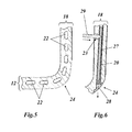
- shows the section through a blade at the transition between the blade airfoil and the platform with a cooling arrangement according to an exemplary embodiment of the invention; and
- Fig. 6
- shows the section through a blade at the transition between the blade airfoil and the platform with a radial passage which is accessible from the bottom and into which is inserted, according to an exemplary embodiment of the method according to the invention, an insert for the machining.
- The present invention deals with a blade for a gas turbine, as is shown by way of example in
Fig. 1 in a perspective side view. Theblade 10, which can be a rotor blade or a stator blade of the gas turbine, comprises ablade airfoil 11 which, as is customary, has a leadingedge 13, a trailing edge 14, apressure side 15 and asuction side 16. Theblade airfoil 11, which extends by its longitudinal axis in the radial direction, merges at the bottom into a platform, forming afillet 24. Theblade airfoil 11 has ablade wall 18 which encloses a hollowinterior space 17. A cooling arrangement 19 (shown by dashed lines) is accommodated in theblade wall 18 and directs a cooling medium, e.g. cooling air, coming from the inside, through the wall and then guides the cooling medium to the outside for forming a cooling film. - The
cooling arrangement 19 in this example comprises a centralradial passage 20 from whichcooling passages radial passage 20 are film-cooling holes 23 through which the cooling medium discharges to the outside for forming a film. With this type of cooling arrangement, it is now essential for the invention that the distribution or density or periodicity of the film-cooling holes 23 is selected independently of the distribution or density or periodicity of thecooling passages blade 10 independently of the internal wall cooling. - In
Fig. 2 , an exemplary embodiment of a cooling arrangement according to the invention is reproduced in cross section (Fig. 2a ) and in side view (Fig. 2b ). Thecooling arrangement 19a has aradial passage 20 from which coolingpassages 21 project equidistantly only towards one side.Turbulence elements 26, which are known per se, can be arranged in thecooling passages 21 in order to improve the heat transfer between the cooling medium and the wall by forming turbulences. Theturbulence elements 26 can be designed in the form of ribs or pins, for example. Furthermore, provision can be made along thecooling passages 21 for impingement cooling holes 25 through which cooling medium flows from theinterior space 17 of theblade 10 into thecooling passages 21 and impinges with cooling effect upon the opposite inner wall of thecooling passages 21. - As can be seen from
Fig. 2a , theradial passage 20 is arranged in an offset manner towards the inside (downward inFig. 2a ) from the middle of theblade wall 18. As a result, the wall section is provided with a greater thickness d between theradial passage 20 and the outer side, which is necessary in order to enable a fan-like arrangement of the film-cooling holes 23 and therefore an improved forming of the cooling films on the outer side. - Other exemplary embodiments of cooling arrangements are reproduced in
Fig. 3 and Fig. 4 . Thecooling arrangement 19b ofFig. 3 is distinguished by the fact that coolingpassages radial passage 20 on both sides and are equipped with corresponding impingement cooling holes 25. The arrangement of thecooling passages radial passage 20 on both sides need not necessarily be symmetrical in this case; thecooling passages radial passage 20. Thecooling arrangement 19c ofFig. 4 is distinguished by the fact that coolingpassages 22 project from theradial passage 20 only on the other side, and that the film-cooling holes 23 have a particularly small spacing in theradial passage 20. - As mentioned already, a special significance is given to the
fillet 24 at the transition between theblade airfoil 11 and theplatform 12 with regard to the cooling. Within the scope of the inventive concept, therefore, according toFig. 5 provision is also made in the region of thefillet 24 in theblade wall 18 for coolingpassages 22 which ensure adequate cooling in the critical region. - With regard to the production of the
blade 10, it is advantageous if theradial passage 20 according toFig. 6 is accessible from one side, especially from the bottom. According to the exemplary embodiment ofFig. 6 , this is achieved by theradial passage 20 opening into the interior space of the blade in the region of the fillet 24 (inFig. 6 , this opening is already sealed off with a sealingelement 28, which, however, happens only after introducing the film-cooling holes 23). If film-cooling holes 23 are to be introduced into the blade from the outside, e.g. by means of laser drilling with alaser beam 29, a strip-like insert 27, which preferably consists of PTFE, is first inserted through the bottom opening into theradial passage 20 in order to protect the opposite inner wall in theradial passage 20 when the holes are being drilled. After the film-cooling holes 23 have been introduced, theinsert 27 is withdrawn from theradial passage 20 and theradial passage 20 is sealed off with the hard-solderedsealing element 28. -
- 10
- Blade (stator blade or rotor blade)
- 11
- Blade airfoil
- 12
- Platform
- 13
- Leading edge
- 14
- Trailing edge
- 15
- Pressure side
- 16
- Suction side
- 17
- Interior space
- 18
- Blade wall
- 19, 19a - c
- Cooling arrangement
- 20
- Radial passage
- 21, 22
- Cooling passage
- 23
- Film-cooling hole
- 24
- Fillet
- 25
- Impingement cooling hole
- 26
- Turbulence element
- 27
- Insert (strip-like)
- 28
- Sealing element
- 29
- Laser beam
Claims (14)
- A blade (10) for a gas turbine, comprising a blade airfoil (11), the blade wall (18) of which encloses an interior space (17), wherein, for cooling the blade wall (18), provision is made in said blade wall (18) for a cooling arrangement (19, 19a - c) which has a radial passage extending (20) in the longitudinal direction of the blade and from which a multiplicity of cooling passages (21, 22), extending in the blade wall (18), branch in the transverse direction, and from which a multiplicity of film-cooling holes (23) are led to the outside in the transverse direction, characterized in that the distribution of the film-cooling holes (23) along the radial passage (20) is selected independently of the distribution of the cooling passages (21, 22) along the radial passage (20).
- The blade as claimed in claim 1, characterized in that the radial passage (20) is arranged in an offset manner towards the inside from the middle of the blade wall (18) in order to enable a fan-like arrangement of the film-cooling holes (23).
- The blade as claimed in claim 1 or 2, characterized in that the radial passage (20) is accessible from the outside at one end and is sealed off there by means of a subsequently attached sealing element (28).
- The blade as claimed in claim 3, characterized in that the blade (10) comprises a platform (12) into which the blade airfoil (11) merges at the lower end, and in that the radial passage (20) is accessible from the outside at the transition between the blade airfoil (11) and the platform (12).
- The blade as claimed in one of claims 1 - 4, characterized in that the blade (10) comprises a platform (12) into which the blade airfoil (11) merges at the lower end, forming a fillet (24), and in that cooling passages (22) are provided in the region of the fillet (24) for cooling the transition region.
- The blade as claimed in one of claims 1 - 5, characterized in that turbulence elements (26), especially in the form of ribs or pins, are provided in the cooling passages (21, 22) for improving the cooling.
- The blade as claimed in one of claims 1 - 6, characterized in that provision is made for impingement cooling holes (25) which lead from the interior space (17) of the blade (10) to the cooling passages (21, 22).
- The blade as claimed in one of claims 1 - 7, characterized in that cooling passages (21, 22) extend from the radial passage (20) only on one side.
- The blade as claimed in one of claims 1 - 7, characterized in that cooling passages (21, 22) extend from the radial passage (20) on both sides.
- The blade as claimed in claim 9, characterized in that the arrangements of the cooling passages (21, 22) projecting from the radial passage (20) on both sides are selected independently of each other.
- A method for producing a blade (10) as claimed in claim 3, characterized in that in a first step, the blade (10) is provided with a radial passage (20) which is open on one side, in that in a second step, a strip-like insert (27) is inserted into the open radial passage (20), in that in a third step, film-cooling holes (23) are introduced into the blade from the outside, wherein the wall of the radial passage (20) opposite the film-cooling holes (23) is protected by means of the insert (27) during the machining, and in that in a fourth step, the insert (27) is removed from the radial passage (20).
- The method as claimed in claim 11, characterized in that the radial passage (20) is sealed off with a sealing element (28) after removing the insert (27).
- The method as claimed in claim 12, characterized in that the sealing element (28) is hard-soldered.
- The method as claimed in one of claims 11 - 13, characterized in that the film-cooling holes (23) are introduced by laser drilling, and in that a PTFE strip is used as the insert (27).
Applications Claiming Priority (1)
| Application Number | Priority Date | Filing Date | Title |
|---|---|---|---|
| CH01093/11A CH705185A1 (en) | 2011-06-29 | 2011-06-29 | Blade for a gas turbine and processes for manufacturing such a blade. |
Publications (2)
| Publication Number | Publication Date |
|---|---|
| EP2540972A1 true EP2540972A1 (en) | 2013-01-02 |
| EP2540972B1 EP2540972B1 (en) | 2016-02-10 |
Family
ID=44534895
Family Applications (1)
| Application Number | Title | Priority Date | Filing Date |
|---|---|---|---|
| EP12173501.3A Active EP2540972B1 (en) | 2011-06-29 | 2012-06-26 | Cooled gas turbine blade |
Country Status (5)
| Country | Link |
|---|---|
| US (1) | US9062555B2 (en) |
| EP (1) | EP2540972B1 (en) |
| JP (1) | JP5730244B2 (en) |
| CN (1) | CN102852562B (en) |
| CH (1) | CH705185A1 (en) |
Cited By (2)
| Publication number | Priority date | Publication date | Assignee | Title |
|---|---|---|---|---|
| WO2014143374A1 (en) * | 2013-03-14 | 2014-09-18 | Okey Kwon | Cooling system and method with trip strips |
| EP3124745A1 (en) * | 2015-07-29 | 2017-02-01 | General Electric Technology GmbH | Turbo-engine component with film cooled wall |
Families Citing this family (8)
| Publication number | Priority date | Publication date | Assignee | Title |
|---|---|---|---|---|
| US10190422B2 (en) | 2016-04-12 | 2019-01-29 | Solar Turbines Incorporated | Rotation enhanced turbine blade cooling |
| US10480327B2 (en) * | 2017-01-03 | 2019-11-19 | General Electric Company | Components having channels for impingement cooling |
| US10641174B2 (en) | 2017-01-18 | 2020-05-05 | General Electric Company | Rotor shaft cooling |
| CN107671435A (en) * | 2017-11-08 | 2018-02-09 | 钦成科技有限公司 | Rear wall protection device and its application method for atomizer punching |
| US10563519B2 (en) * | 2018-02-19 | 2020-02-18 | General Electric Company | Engine component with cooling hole |
| FR3079262B1 (en) * | 2018-03-23 | 2022-07-22 | Safran Helicopter Engines | TURBINE FIXED BLADE COOLED BY IMPACTS OF AIR JETS |
| JP7206129B2 (en) * | 2019-02-26 | 2023-01-17 | 三菱重工業株式会社 | wings and machines equipped with them |
| CN110394610A (en) * | 2019-08-30 | 2019-11-01 | 中国航发动力股份有限公司 | A processing method of a gas turbine power turbine blade |
Citations (6)
| Publication number | Priority date | Publication date | Assignee | Title |
|---|---|---|---|---|
| US5667359A (en) * | 1988-08-24 | 1997-09-16 | United Technologies Corp. | Clearance control for the turbine of a gas turbine engine |
| US5702232A (en) * | 1994-12-13 | 1997-12-30 | United Technologies Corporation | Cooled airfoils for a gas turbine engine |
| US6379118B2 (en) | 2000-01-13 | 2002-04-30 | Alstom (Switzerland) Ltd | Cooled blade for a gas turbine |
| EP1267040A2 (en) * | 2001-06-11 | 2002-12-18 | ALSTOM (Switzerland) Ltd | Gas turbine blade |
| US20080166240A1 (en) * | 2007-01-04 | 2008-07-10 | Siemens Power Generation, Inc. | Advanced cooling method for combustion turbine airfoil fillets |
| GB2460936A (en) * | 2008-06-18 | 2009-12-23 | Gen Electric | Turbine airfoil cooling |
Family Cites Families (6)
| Publication number | Priority date | Publication date | Assignee | Title |
|---|---|---|---|---|
| GB1175816A (en) | 1968-06-24 | 1969-12-23 | Rolls Royce | Improvements relating to the Cooling of Aerofoil Shaped Blades |
| JPS5817323B2 (en) | 1974-09-05 | 1983-04-06 | 株式会社東芝 | Gaster Binyoku |
| US6254347B1 (en) * | 1999-11-03 | 2001-07-03 | General Electric Company | Striated cooling hole |
| US7217095B2 (en) * | 2004-11-09 | 2007-05-15 | United Technologies Corporation | Heat transferring cooling features for an airfoil |
| US8109725B2 (en) * | 2008-12-15 | 2012-02-07 | United Technologies Corporation | Airfoil with wrapped leading edge cooling passage |
| US8535004B2 (en) * | 2010-03-26 | 2013-09-17 | Siemens Energy, Inc. | Four-wall turbine airfoil with thermal strain control for reduced cycle fatigue |
-
2011
- 2011-06-29 CH CH01093/11A patent/CH705185A1/en not_active Application Discontinuation
-
2012
- 2012-06-20 US US13/528,013 patent/US9062555B2/en active Active
- 2012-06-26 EP EP12173501.3A patent/EP2540972B1/en active Active
- 2012-06-28 CN CN201210222050.5A patent/CN102852562B/en active Active
- 2012-06-28 JP JP2012145907A patent/JP5730244B2/en not_active Expired - Fee Related
Patent Citations (6)
| Publication number | Priority date | Publication date | Assignee | Title |
|---|---|---|---|---|
| US5667359A (en) * | 1988-08-24 | 1997-09-16 | United Technologies Corp. | Clearance control for the turbine of a gas turbine engine |
| US5702232A (en) * | 1994-12-13 | 1997-12-30 | United Technologies Corporation | Cooled airfoils for a gas turbine engine |
| US6379118B2 (en) | 2000-01-13 | 2002-04-30 | Alstom (Switzerland) Ltd | Cooled blade for a gas turbine |
| EP1267040A2 (en) * | 2001-06-11 | 2002-12-18 | ALSTOM (Switzerland) Ltd | Gas turbine blade |
| US20080166240A1 (en) * | 2007-01-04 | 2008-07-10 | Siemens Power Generation, Inc. | Advanced cooling method for combustion turbine airfoil fillets |
| GB2460936A (en) * | 2008-06-18 | 2009-12-23 | Gen Electric | Turbine airfoil cooling |
Cited By (3)
| Publication number | Priority date | Publication date | Assignee | Title |
|---|---|---|---|---|
| WO2014143374A1 (en) * | 2013-03-14 | 2014-09-18 | Okey Kwon | Cooling system and method with trip strips |
| EP3124745A1 (en) * | 2015-07-29 | 2017-02-01 | General Electric Technology GmbH | Turbo-engine component with film cooled wall |
| US10655474B2 (en) | 2015-07-29 | 2020-05-19 | General Electric Technology Gmbh | Turbo-engine component having outer wall discharge openings |
Also Published As
| Publication number | Publication date |
|---|---|
| EP2540972B1 (en) | 2016-02-10 |
| US9062555B2 (en) | 2015-06-23 |
| CN102852562B (en) | 2016-05-11 |
| CN102852562A (en) | 2013-01-02 |
| JP2013011278A (en) | 2013-01-17 |
| CH705185A1 (en) | 2012-12-31 |
| US20130004332A1 (en) | 2013-01-03 |
| JP5730244B2 (en) | 2015-06-03 |
Similar Documents
| Publication | Publication Date | Title |
|---|---|---|
| EP2540972B1 (en) | Cooled gas turbine blade | |
| US8251660B1 (en) | Turbine airfoil with near wall vortex cooling | |
| EP2860359B1 (en) | Arrangement for cooling a component in the hot gas path of a gas turbine | |
| US8608430B1 (en) | Turbine vane with near wall multiple impingement cooling | |
| EP2230383A1 (en) | Blade for a gas turbine with cooled tip cap | |
| CN101535602B (en) | Turbine blade | |
| US8096767B1 (en) | Turbine blade with serpentine cooling circuit formed within the tip shroud | |
| CN101922353B (en) | Feeding film cooling hole from seal slot | |
| JP6405102B2 (en) | Turbine airfoil assembly | |
| US7955053B1 (en) | Turbine blade with serpentine cooling circuit | |
| CN104379873B (en) | Turbine airfoil device and correlation method | |
| CN101482029B (en) | Turbine blade tip shroud | |
| EP2607624A1 (en) | Vane for a turbomachine | |
| US20060073015A1 (en) | Gas turbine airfoil film cooling hole | |
| US8613597B1 (en) | Turbine blade with trailing edge cooling | |
| US8118554B1 (en) | Turbine vane with endwall cooling | |
| JP5868609B2 (en) | Gas turbine blade and method for manufacturing the same | |
| US8366393B2 (en) | Rotor blade | |
| EP2917494B1 (en) | Blade for a turbomachine | |
| JP6514509B2 (en) | Turbine component with bimaterial adaptive cooling passage | |
| US8757961B1 (en) | Industrial turbine stator vane | |
| EP2639405B1 (en) | Turbine blade tip cooling | |
| JP5856731B2 (en) | Turbine end wall cooling configuration | |
| CN101482032A (en) | Turbine blade tip shroud | |
| JP6632219B2 (en) | Cooling structure for fixed blade |
Legal Events
| Date | Code | Title | Description |
|---|---|---|---|
| PUAI | Public reference made under article 153(3) epc to a published international application that has entered the european phase |
Free format text: ORIGINAL CODE: 0009012 |
|
| AK | Designated contracting states |
Kind code of ref document: A1 Designated state(s): AL AT BE BG CH CY CZ DE DK EE ES FI FR GB GR HR HU IE IS IT LI LT LU LV MC MK MT NL NO PL PT RO RS SE SI SK SM TR |
|
| AX | Request for extension of the european patent |
Extension state: BA ME |
|
| 17P | Request for examination filed |
Effective date: 20130624 |
|
| RBV | Designated contracting states (corrected) |
Designated state(s): AL AT BE BG CH CY CZ DE DK EE ES FI FR GB GR HR HU IE IS IT LI LT LU LV MC MK MT NL NO PL PT RO RS SE SI SK SM TR |
|
| GRAP | Despatch of communication of intention to grant a patent |
Free format text: ORIGINAL CODE: EPIDOSNIGR1 |
|
| INTG | Intention to grant announced |
Effective date: 20150804 |
|
| GRAS | Grant fee paid |
Free format text: ORIGINAL CODE: EPIDOSNIGR3 |
|
| GRAA | (expected) grant |
Free format text: ORIGINAL CODE: 0009210 |
|
| AK | Designated contracting states |
Kind code of ref document: B1 Designated state(s): AL AT BE BG CH CY CZ DE DK EE ES FI FR GB GR HR HU IE IS IT LI LT LU LV MC MK MT NL NO PL PT RO RS SE SI SK SM TR |
|
| REG | Reference to a national code |
Ref country code: GB Ref legal event code: FG4D |
|
| REG | Reference to a national code |
Ref country code: AT Ref legal event code: REF Ref document number: 774759 Country of ref document: AT Kind code of ref document: T Effective date: 20160215 Ref country code: CH Ref legal event code: EP |
|
| REG | Reference to a national code |
Ref country code: IE Ref legal event code: FG4D |
|
| REG | Reference to a national code |
Ref country code: DE Ref legal event code: R096 Ref document number: 602012014624 Country of ref document: DE |
|
| REG | Reference to a national code |
Ref country code: LT Ref legal event code: MG4D |
|
| REG | Reference to a national code |
Ref country code: NL Ref legal event code: MP Effective date: 20160210 |
|
| REG | Reference to a national code |
Ref country code: AT Ref legal event code: MK05 Ref document number: 774759 Country of ref document: AT Kind code of ref document: T Effective date: 20160210 |
|
| PG25 | Lapsed in a contracting state [announced via postgrant information from national office to epo] |
Ref country code: HR Free format text: LAPSE BECAUSE OF FAILURE TO SUBMIT A TRANSLATION OF THE DESCRIPTION OR TO PAY THE FEE WITHIN THE PRESCRIBED TIME-LIMIT Effective date: 20160210 Ref country code: GR Free format text: LAPSE BECAUSE OF FAILURE TO SUBMIT A TRANSLATION OF THE DESCRIPTION OR TO PAY THE FEE WITHIN THE PRESCRIBED TIME-LIMIT Effective date: 20160511 Ref country code: NO Free format text: LAPSE BECAUSE OF FAILURE TO SUBMIT A TRANSLATION OF THE DESCRIPTION OR TO PAY THE FEE WITHIN THE PRESCRIBED TIME-LIMIT Effective date: 20160510 Ref country code: FI Free format text: LAPSE BECAUSE OF FAILURE TO SUBMIT A TRANSLATION OF THE DESCRIPTION OR TO PAY THE FEE WITHIN THE PRESCRIBED TIME-LIMIT Effective date: 20160210 Ref country code: ES Free format text: LAPSE BECAUSE OF FAILURE TO SUBMIT A TRANSLATION OF THE DESCRIPTION OR TO PAY THE FEE WITHIN THE PRESCRIBED TIME-LIMIT Effective date: 20160210 |
|
| RAP2 | Party data changed (patent owner data changed or rights of a patent transferred) |
Owner name: GENERAL ELECTRIC TECHNOLOGY GMBH |
|
| PG25 | Lapsed in a contracting state [announced via postgrant information from national office to epo] |
Ref country code: RS Free format text: LAPSE BECAUSE OF FAILURE TO SUBMIT A TRANSLATION OF THE DESCRIPTION OR TO PAY THE FEE WITHIN THE PRESCRIBED TIME-LIMIT Effective date: 20160210 Ref country code: PT Free format text: LAPSE BECAUSE OF FAILURE TO SUBMIT A TRANSLATION OF THE DESCRIPTION OR TO PAY THE FEE WITHIN THE PRESCRIBED TIME-LIMIT Effective date: 20160613 Ref country code: SE Free format text: LAPSE BECAUSE OF FAILURE TO SUBMIT A TRANSLATION OF THE DESCRIPTION OR TO PAY THE FEE WITHIN THE PRESCRIBED TIME-LIMIT Effective date: 20160210 Ref country code: IS Free format text: LAPSE BECAUSE OF FAILURE TO SUBMIT A TRANSLATION OF THE DESCRIPTION OR TO PAY THE FEE WITHIN THE PRESCRIBED TIME-LIMIT Effective date: 20160610 Ref country code: NL Free format text: LAPSE BECAUSE OF FAILURE TO SUBMIT A TRANSLATION OF THE DESCRIPTION OR TO PAY THE FEE WITHIN THE PRESCRIBED TIME-LIMIT Effective date: 20160210 Ref country code: LV Free format text: LAPSE BECAUSE OF FAILURE TO SUBMIT A TRANSLATION OF THE DESCRIPTION OR TO PAY THE FEE WITHIN THE PRESCRIBED TIME-LIMIT Effective date: 20160210 Ref country code: AT Free format text: LAPSE BECAUSE OF FAILURE TO SUBMIT A TRANSLATION OF THE DESCRIPTION OR TO PAY THE FEE WITHIN THE PRESCRIBED TIME-LIMIT Effective date: 20160210 Ref country code: PL Free format text: LAPSE BECAUSE OF FAILURE TO SUBMIT A TRANSLATION OF THE DESCRIPTION OR TO PAY THE FEE WITHIN THE PRESCRIBED TIME-LIMIT Effective date: 20160210 Ref country code: LT Free format text: LAPSE BECAUSE OF FAILURE TO SUBMIT A TRANSLATION OF THE DESCRIPTION OR TO PAY THE FEE WITHIN THE PRESCRIBED TIME-LIMIT Effective date: 20160210 |
|
| PG25 | Lapsed in a contracting state [announced via postgrant information from national office to epo] |
Ref country code: DK Free format text: LAPSE BECAUSE OF FAILURE TO SUBMIT A TRANSLATION OF THE DESCRIPTION OR TO PAY THE FEE WITHIN THE PRESCRIBED TIME-LIMIT Effective date: 20160210 Ref country code: EE Free format text: LAPSE BECAUSE OF FAILURE TO SUBMIT A TRANSLATION OF THE DESCRIPTION OR TO PAY THE FEE WITHIN THE PRESCRIBED TIME-LIMIT Effective date: 20160210 |
|
| REG | Reference to a national code |
Ref country code: DE Ref legal event code: R097 Ref document number: 602012014624 Country of ref document: DE |
|
| PG25 | Lapsed in a contracting state [announced via postgrant information from national office to epo] |
Ref country code: SK Free format text: LAPSE BECAUSE OF FAILURE TO SUBMIT A TRANSLATION OF THE DESCRIPTION OR TO PAY THE FEE WITHIN THE PRESCRIBED TIME-LIMIT Effective date: 20160210 Ref country code: RO Free format text: LAPSE BECAUSE OF FAILURE TO SUBMIT A TRANSLATION OF THE DESCRIPTION OR TO PAY THE FEE WITHIN THE PRESCRIBED TIME-LIMIT Effective date: 20160210 Ref country code: SM Free format text: LAPSE BECAUSE OF FAILURE TO SUBMIT A TRANSLATION OF THE DESCRIPTION OR TO PAY THE FEE WITHIN THE PRESCRIBED TIME-LIMIT Effective date: 20160210 Ref country code: CZ Free format text: LAPSE BECAUSE OF FAILURE TO SUBMIT A TRANSLATION OF THE DESCRIPTION OR TO PAY THE FEE WITHIN THE PRESCRIBED TIME-LIMIT Effective date: 20160210 |
|
| PLBE | No opposition filed within time limit |
Free format text: ORIGINAL CODE: 0009261 |
|
| STAA | Information on the status of an ep patent application or granted ep patent |
Free format text: STATUS: NO OPPOSITION FILED WITHIN TIME LIMIT |
|
| PG25 | Lapsed in a contracting state [announced via postgrant information from national office to epo] |
Ref country code: BE Free format text: LAPSE BECAUSE OF FAILURE TO SUBMIT A TRANSLATION OF THE DESCRIPTION OR TO PAY THE FEE WITHIN THE PRESCRIBED TIME-LIMIT Effective date: 20160210 |
|
| 26N | No opposition filed |
Effective date: 20161111 |
|
| PG25 | Lapsed in a contracting state [announced via postgrant information from national office to epo] |
Ref country code: MC Free format text: LAPSE BECAUSE OF FAILURE TO SUBMIT A TRANSLATION OF THE DESCRIPTION OR TO PAY THE FEE WITHIN THE PRESCRIBED TIME-LIMIT Effective date: 20160210 |
|
| REG | Reference to a national code |
Ref country code: CH Ref legal event code: PL |
|
| PG25 | Lapsed in a contracting state [announced via postgrant information from national office to epo] |
Ref country code: BG Free format text: LAPSE BECAUSE OF FAILURE TO SUBMIT A TRANSLATION OF THE DESCRIPTION OR TO PAY THE FEE WITHIN THE PRESCRIBED TIME-LIMIT Effective date: 20160510 Ref country code: SI Free format text: LAPSE BECAUSE OF FAILURE TO SUBMIT A TRANSLATION OF THE DESCRIPTION OR TO PAY THE FEE WITHIN THE PRESCRIBED TIME-LIMIT Effective date: 20160210 |
|
| REG | Reference to a national code |
Ref country code: IE Ref legal event code: MM4A |
|
| REG | Reference to a national code |
Ref country code: FR Ref legal event code: ST Effective date: 20170228 |
|
| REG | Reference to a national code |
Ref country code: DE Ref legal event code: R081 Ref document number: 602012014624 Country of ref document: DE Owner name: GENERAL ELECTRIC TECHNOLOGY GMBH, CH Free format text: FORMER OWNER: ALSTOM TECHNOLOGY LTD., BADEN, CH Ref country code: DE Ref legal event code: R081 Ref document number: 602012014624 Country of ref document: DE Owner name: ANSALDO ENERGIA SWITZERLAND AG, CH Free format text: FORMER OWNER: ALSTOM TECHNOLOGY LTD., BADEN, CH Ref country code: DE Ref legal event code: R082 Ref document number: 602012014624 Country of ref document: DE Representative=s name: DREISS PATENTANWAELTE PARTG MBB, DE |
|
| PG25 | Lapsed in a contracting state [announced via postgrant information from national office to epo] |
Ref country code: FR Free format text: LAPSE BECAUSE OF NON-PAYMENT OF DUE FEES Effective date: 20160630 Ref country code: CH Free format text: LAPSE BECAUSE OF NON-PAYMENT OF DUE FEES Effective date: 20160630 Ref country code: LI Free format text: LAPSE BECAUSE OF NON-PAYMENT OF DUE FEES Effective date: 20160630 |
|
| PG25 | Lapsed in a contracting state [announced via postgrant information from national office to epo] |
Ref country code: IE Free format text: LAPSE BECAUSE OF NON-PAYMENT OF DUE FEES Effective date: 20160626 |
|
| REG | Reference to a national code |
Ref country code: DE Ref legal event code: R082 Ref document number: 602012014624 Country of ref document: DE Representative=s name: DREISS PATENTANWAELTE PARTG MBB, DE Ref country code: DE Ref legal event code: R081 Ref document number: 602012014624 Country of ref document: DE Owner name: ANSALDO ENERGIA SWITZERLAND AG, CH Free format text: FORMER OWNER: GENERAL ELECTRIC TECHNOLOGY GMBH, BADEN, CH |
|
| REG | Reference to a national code |
Ref country code: GB Ref legal event code: 732E Free format text: REGISTERED BETWEEN 20171102 AND 20171108 |
|
| PG25 | Lapsed in a contracting state [announced via postgrant information from national office to epo] |
Ref country code: CY Free format text: LAPSE BECAUSE OF FAILURE TO SUBMIT A TRANSLATION OF THE DESCRIPTION OR TO PAY THE FEE WITHIN THE PRESCRIBED TIME-LIMIT Effective date: 20160210 Ref country code: HU Free format text: LAPSE BECAUSE OF FAILURE TO SUBMIT A TRANSLATION OF THE DESCRIPTION OR TO PAY THE FEE WITHIN THE PRESCRIBED TIME-LIMIT; INVALID AB INITIO Effective date: 20120626 |
|
| PG25 | Lapsed in a contracting state [announced via postgrant information from national office to epo] |
Ref country code: LU Free format text: LAPSE BECAUSE OF NON-PAYMENT OF DUE FEES Effective date: 20160626 Ref country code: MK Free format text: LAPSE BECAUSE OF FAILURE TO SUBMIT A TRANSLATION OF THE DESCRIPTION OR TO PAY THE FEE WITHIN THE PRESCRIBED TIME-LIMIT Effective date: 20160210 Ref country code: MT Free format text: LAPSE BECAUSE OF NON-PAYMENT OF DUE FEES Effective date: 20160630 Ref country code: TR Free format text: LAPSE BECAUSE OF FAILURE TO SUBMIT A TRANSLATION OF THE DESCRIPTION OR TO PAY THE FEE WITHIN THE PRESCRIBED TIME-LIMIT Effective date: 20160210 |
|
| PG25 | Lapsed in a contracting state [announced via postgrant information from national office to epo] |
Ref country code: AL Free format text: LAPSE BECAUSE OF FAILURE TO SUBMIT A TRANSLATION OF THE DESCRIPTION OR TO PAY THE FEE WITHIN THE PRESCRIBED TIME-LIMIT Effective date: 20160210 |
|
| P01 | Opt-out of the competence of the unified patent court (upc) registered |
Effective date: 20240430 |
|
| PGFP | Annual fee paid to national office [announced via postgrant information from national office to epo] |
Ref country code: DE Payment date: 20250618 Year of fee payment: 14 |
|
| PGFP | Annual fee paid to national office [announced via postgrant information from national office to epo] |
Ref country code: GB Payment date: 20250620 Year of fee payment: 14 |
|
| PGFP | Annual fee paid to national office [announced via postgrant information from national office to epo] |
Ref country code: IT Payment date: 20250630 Year of fee payment: 14 |