EP2540964A2 - System and method for supporting a nozzle assembly - Google Patents
System and method for supporting a nozzle assembly Download PDFInfo
- Publication number
- EP2540964A2 EP2540964A2 EP12172567A EP12172567A EP2540964A2 EP 2540964 A2 EP2540964 A2 EP 2540964A2 EP 12172567 A EP12172567 A EP 12172567A EP 12172567 A EP12172567 A EP 12172567A EP 2540964 A2 EP2540964 A2 EP 2540964A2
- Authority
- EP
- European Patent Office
- Prior art keywords
- nozzle assembly
- stationary component
- supporting
- radially
- support
- Prior art date
- Legal status (The legal status is an assumption and is not a legal conclusion. Google has not performed a legal analysis and makes no representation as to the accuracy of the status listed.)
- Granted
Links
- 238000000034 method Methods 0.000 title claims abstract description 24
- 230000000712 assembly Effects 0.000 description 16
- 238000000429 assembly Methods 0.000 description 16
- 230000000694 effects Effects 0.000 description 14
- 239000012530 fluid Substances 0.000 description 8
- 238000001816 cooling Methods 0.000 description 3
- 239000000463 material Substances 0.000 description 3
- 230000002787 reinforcement Effects 0.000 description 3
- 230000004323 axial length Effects 0.000 description 2
- 238000004519 manufacturing process Methods 0.000 description 2
- 238000012986 modification Methods 0.000 description 2
- 230000004048 modification Effects 0.000 description 2
- 230000003014 reinforcing effect Effects 0.000 description 2
- 229910000601 superalloy Inorganic materials 0.000 description 2
- 239000002826 coolant Substances 0.000 description 1
- 230000001419 dependent effect Effects 0.000 description 1
- 230000007246 mechanism Effects 0.000 description 1
- 230000008439 repair process Effects 0.000 description 1
Images
Classifications
-
- F—MECHANICAL ENGINEERING; LIGHTING; HEATING; WEAPONS; BLASTING
- F01—MACHINES OR ENGINES IN GENERAL; ENGINE PLANTS IN GENERAL; STEAM ENGINES
- F01D—NON-POSITIVE DISPLACEMENT MACHINES OR ENGINES, e.g. STEAM TURBINES
- F01D5/00—Blades; Blade-carrying members; Heating, heat-insulating, cooling or antivibration means on the blades or the members
- F01D5/12—Blades
- F01D5/14—Form or construction
- F01D5/147—Construction, i.e. structural features, e.g. of weight-saving hollow blades
-
- F—MECHANICAL ENGINEERING; LIGHTING; HEATING; WEAPONS; BLASTING
- F01—MACHINES OR ENGINES IN GENERAL; ENGINE PLANTS IN GENERAL; STEAM ENGINES
- F01D—NON-POSITIVE DISPLACEMENT MACHINES OR ENGINES, e.g. STEAM TURBINES
- F01D25/00—Component parts, details, or accessories, not provided for in, or of interest apart from, other groups
- F01D25/24—Casings; Casing parts, e.g. diaphragms, casing fastenings
- F01D25/246—Fastening of diaphragms or stator-rings
-
- F—MECHANICAL ENGINEERING; LIGHTING; HEATING; WEAPONS; BLASTING
- F01—MACHINES OR ENGINES IN GENERAL; ENGINE PLANTS IN GENERAL; STEAM ENGINES
- F01D—NON-POSITIVE DISPLACEMENT MACHINES OR ENGINES, e.g. STEAM TURBINES
- F01D9/00—Stators
- F01D9/02—Nozzles; Nozzle boxes; Stator blades; Guide conduits, e.g. individual nozzles
- F01D9/04—Nozzles; Nozzle boxes; Stator blades; Guide conduits, e.g. individual nozzles forming ring or sector
- F01D9/041—Nozzles; Nozzle boxes; Stator blades; Guide conduits, e.g. individual nozzles forming ring or sector using blades
-
- Y—GENERAL TAGGING OF NEW TECHNOLOGICAL DEVELOPMENTS; GENERAL TAGGING OF CROSS-SECTIONAL TECHNOLOGIES SPANNING OVER SEVERAL SECTIONS OF THE IPC; TECHNICAL SUBJECTS COVERED BY FORMER USPC CROSS-REFERENCE ART COLLECTIONS [XRACs] AND DIGESTS
- Y10—TECHNICAL SUBJECTS COVERED BY FORMER USPC
- Y10T—TECHNICAL SUBJECTS COVERED BY FORMER US CLASSIFICATION
- Y10T29/00—Metal working
- Y10T29/49—Method of mechanical manufacture
- Y10T29/49826—Assembling or joining
Definitions
- the present invention generally involves a system and method for supporting a nozzle assembly.
- a support extends radially through a portion of the nozzle assembly to reduce the effects of creep in the nozzle assembly.
- Nozzle assemblies also referred to as stators or stator assemblies, are commonly included in various forms of commercial equipment.
- compressors and turbines generally include alternating stages of nozzle assemblies and rotating blades as is known in the art.
- Each nozzle assembly generally comprises one or more airfoils connected to an outer sidewall and an inner sidewall.
- the outer sidewall is typically fixedly attached to a stationary component, such as a shroud or casing, and the inner sidewall is typically proximate to one or more rotating components, such as a rotor or rotor wheel.
- the outer sidewall provides a cantilevered support for the nozzle assembly, with the airfoils extending radially inward substantially perpendicular to a fluid flow to direct the fluid flow onto a downstream stage of rotating blades or buckets.
- the fluid flow over the nozzle assemblies may plastically deform the shape and/or profile of the nozzle assemblies, a condition also known as "creep.”
- the effects of creep is one of the main failure mechanisms in a gas turbine having cantilevered nozzle assemblies.
- the fluid flow over the nozzle assemblies causes the inner sidewall to move in the direction of the fluid flow. Deflection of the inner sidewall may reduce the clearance between the inner sidewall and the rotating components, restricting cooling flow between the inner sidewall and the rotating components. The reduced cooling flow between the inner sidewall and the rotating components may lead to excessive temperatures and ultimately failure of the rotating components.
- the stationary nozzle assemblies may crack and/or deflect into the rotating components, causing substantial damage and requiring costly repairs to both the stationary nozzle assemblies and the rotating components.
- the axial length of the nozzle assemblies may be required to increase in order to reduce the amount or effect of creep that occurs in the nozzle assemblies over the expected life, resulting in a corresponding increase in the length of the compressor or turbine.
- the present invention resides in a system for supporting a nozzle assembly that includes a first member connected to a stationary component and a second member extending from the first member radially through at least a portion of the nozzle assembly. A distal end of the second member is radially displaced from the first member and configured to contact the nozzle assembly.
- the present invention also resides in a method for supporting a nozzle assembly.
- the method includes connecting a first member to a stationary component and extending a second member from the first member radially through at least a portion of the nozzle assembly.
- the method further includes contacting a distal end of the second member to the nozzle assembly, wherein the distal end is radially displaced from the first member.
- a support connected to one or more stationary components extends radially inside at least a portion of the nozzle assembly and connects to the nozzle assembly.
- the support may be thermally isolated from the high temperatures associated with fluid flow through a hot gas path.
- the shape of the support is not required to be aerodynamic and may instead comprise a shape more ideally suited for mechanically reinforcing the nozzle assembly. The additional mechanical reinforcement provided by the support may thus allow less expensive materials to be used in the manufacture of the nozzle assembly, reduced cooling flow through the nozzle assembly, and/or larger nozzle assemblies.
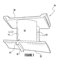
- Figure 1 shows an exemplary nozzle assembly 10 that might be included for example in a compressor or a turbine to provide context for various embodiments of the present invention.
- the exemplary nozzle assembly 10 generally includes a pair of vanes 12, with each vane 12 having a leading edge 14, a trailing edge 16, a vacuum side 18, and a pressure side (not visible).
- the leading-edge 14 is typically rounded, and the trailing edge 16 is typically pointed.
- the vacuum side 18 typically has a convex curvature, and the pressure side typically has a concave curvature.
- the leading-edge 14, trailing edge 16, vacuum side 18, and pressure side combine to form an airfoil for each vane 12.
- an inner sidewall 22 and an outer sidewall 24 may connect the pair of vanes 12 to form the nozzle assembly 10.
- the outer sidewall 24 is then typically fixedly connected to a stationary component, such a shroud or casing of a compressor or turbine, and the inner sidewall 22 is typically proximate to a rotating component, such as a rotor or rotor wheels.
- a working fluid may flow from left to right as shown in Figure 1 between the pair of vanes 12 and the inner and outer sidewalls 22, 24 to the downstream components.
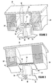
- Figures 2 and 3 provide perspective views of the system for supporting the nozzle assembly 10 shown in Figure 1 according to first and second embodiments of the present invention.
- the system generally comprises a support 30 connected to a stationary component proximate to the nozzle assembly 10.
- the stationery component may comprise, for example, a casing 32 that encloses the compressor or turbine, as shown in Figure 2 , or a shroud 34 that defines the outer perimeter of the hot gas path, as shown in Figure 3 .
- the stationary component may comprise virtually any structure that provides a suitable anchor for holding the support 30 firmly in place, and the present invention is not limited to any particular stationary component unless specifically recited in the claims.
- the support 30 may comprise a plurality of segments formed from a superalloy or other material capable of providing the desired structural reinforcement to the nozzle assembly 10.
- the support 30 may comprise a first member 36 and a second member 38, with the particular orientation or geometry of the first and second members 36, 38 dependent on the particular embodiment.
- the first and second members 36, 38 may be aligned approximately parallel to one another, with the first member 36 extending radially and fixedly connected to the casing 32 and the second member 38 extending inward from the first member 36 radially through at least a portion of the nozzle assembly 10.
- the first and second members 36, 38 may be aligned approximately perpendicular to one another, with the first member 36 extending axially and fixedly connected to the shroud 34 and the second member 38 again extending inward from the first member 36 radially through at least a portion of the nozzle assembly 10.
- the second member 38 may include a distal end 40 radially displaced from the first member 36 and configured to contact the nozzle assembly 10.
- the distal end 40 is configured to abut or contact a land 42 on the inner sidewall 22 of the nozzle assembly 10.
- the support 30 extends radially through at least a portion of the nozzle assembly 10 and contacts the nozzle assembly 10.
- the distal end 40 of the second member 38 inhibits or limits movement of the inner sidewall 22 by transferring the force through the support 30 to the stationary component.
- the support 30 is located inside at least a portion of the nozzle assembly 10 and the space between the nozzle assembly 10 and the casing 32 and is therefore not exposed to the hot gas path of the fluid flow. As a result, the support 30 is effectively thermally isolated from the hot gas path and remains relatively unaffected by the higher temperatures associated with the hot gas path compared to the nozzle assembly 10.
- the shape of the support 30 is not required to be aerodynamic and may instead comprise a shape more ideally suited for mechanically reinforcing the nozzle assembly 10.
- the first and/or second members 36, 38 may comprise a tube or cylinder that resists the effects of creep much more effectively than the airfoil of the nozzle assembly 10.
- the first and/or second members 36, 38 may comprise a square or rectangular I-beam that is similarly better suited to resist the effects of creep compared to the airfoil of the nozzle assembly 10.
- the system may further include means for connecting at least a portion of the support 30 to the stationary component proximate to the nozzle assembly 10.
- the means may comprise any suitable structure or device for connecting one component to another.
- the means may comprise a threaded engagement, and hasp, a clamp, or, as shown in Figures 2 and 3 , a recess or indent 44 in the stationary component that securely holds the first member 36 of the support 30 in place and limits or restricts movement of the first member 36 with respect to the stationary component.
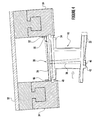
- Figure 4 provides a side view of the system for supporting the nozzle assembly 10 shown in Figure 1 according to an additional embodiment of the present invention.
- the means for connecting at least a portion of the support 30 to the stationary component may comprise one or more detents or stops attached to the shroud 34 or other stationary component.
- a first detent 46 may fixedly connect a first end 48 of the first member 36 to the shroud 34.
- a second end 50 of the first member 36 axially displaced from the first end 48 is slidingly engaged with the shroud 34 and may move with respect to the shroud 34, and a second detent 52 located proximate to the second end 50 limits movement of the second end 50 with respect to the shroud 34.
- the land 42 on the inner sidewall 22 of the nozzle assembly 10 forces the distal end 40 of the second member 38 to the right.
- the support 30 rotates counterclockwise until the second end 50 of the first member 36 abuts or contacts the second detent 52.
- the second detent 52 prevents or limits further movement of the support 30 which in turn prevents or limits further movement of the inner sidewall 22.
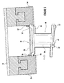
- Figure 5 provides a side view of the system for supporting the nozzle assembly 10 shown in Figure 1 according to yet another embodiment of the present invention.
- the first and second detents 46, 52 connect the first and second ends 48, 50 of the first member 36 to the shroud 34 or other stationary component.
- the land 42 on the inner sidewall 22 of the nozzle assembly 10 moves to the right until it abuts or contacts with the distal end 40 of the second member 38.
- the distal end 40 of the second member 38 transfers the force applied by the land 42 through the support 30 to the first and second detents 46, 52.
- the first and second detents 46, 52 prevent or limit movement of the support 30 which in turn prevents or limits further movement of the inner sidewall 22.
- the various embodiments shown in Figures 2-5 may also be used to provide a method for supporting the nozzle assembly 10.
- the method generally includes connecting the first member 36 to the stationary component, such as the casing 32 or shroud 34.
- the method further includes extending the second member 38 inward from the first member 36 radially through at least a portion of the nozzle assembly 10 and contacting the distal end 40 of the second member 38 to the nozzle assembly 10.
- the method may further include aligning the first member 36 approximately perpendicular to or parallel to the second member 38.
- the method may include slidingly connecting the second end 50 of said first member 38 to the stationary component and contacting the second end 50 of said first member 38 with the second detent 52 to limit movement of the second end 50.
- the various embodiments described and illustrated with respect to Figures 2-5 provide several advantages over existing techniques to limit or prevent the effects of creep.
- the reinforcement provided by the support 30 to the nozzle assembly 10 allows the nozzle assembly 10 to be exposed to higher temperatures without increasing the amount of creep produced in the nozzle assembly 10.
- the nozzle assembly 10 may be manufactured using less expensive materials that no are longer required to withstand the effects of creep.
- the support 30 may allow the axial length of the nozzle assembly 10 to be reduced, reducing the overall length of the turbine or compressor.
Landscapes
- Engineering & Computer Science (AREA)
- Mechanical Engineering (AREA)
- General Engineering & Computer Science (AREA)
- Architecture (AREA)
- Turbine Rotor Nozzle Sealing (AREA)
- Casting Support Devices, Ladles, And Melt Control Thereby (AREA)
Abstract
Description
- The present invention generally involves a system and method for supporting a nozzle assembly. In particular embodiments of the present invention, a support extends radially through a portion of the nozzle assembly to reduce the effects of creep in the nozzle assembly.
- Nozzle assemblies, also referred to as stators or stator assemblies, are commonly included in various forms of commercial equipment. For example, compressors and turbines generally include alternating stages of nozzle assemblies and rotating blades as is known in the art. Each nozzle assembly generally comprises one or more airfoils connected to an outer sidewall and an inner sidewall. The outer sidewall is typically fixedly attached to a stationary component, such as a shroud or casing, and the inner sidewall is typically proximate to one or more rotating components, such as a rotor or rotor wheel. In this manner, the outer sidewall provides a cantilevered support for the nozzle assembly, with the airfoils extending radially inward substantially perpendicular to a fluid flow to direct the fluid flow onto a downstream stage of rotating blades or buckets.
- Over time, the fluid flow over the nozzle assemblies may plastically deform the shape and/or profile of the nozzle assemblies, a condition also known as "creep." The effects of creep is one of the main failure mechanisms in a gas turbine having cantilevered nozzle assemblies. Specifically, over time the fluid flow over the nozzle assemblies causes the inner sidewall to move in the direction of the fluid flow. Deflection of the inner sidewall may reduce the clearance between the inner sidewall and the rotating components, restricting cooling flow between the inner sidewall and the rotating components. The reduced cooling flow between the inner sidewall and the rotating components may lead to excessive temperatures and ultimately failure of the rotating components. In addition, excessive creep may cause the stationary nozzle assemblies to crack and/or deflect into the rotating components, causing substantial damage and requiring costly repairs to both the stationary nozzle assemblies and the rotating components. As a result, the axial length of the nozzle assemblies may be required to increase in order to reduce the amount or effect of creep that occurs in the nozzle assemblies over the expected life, resulting in a corresponding increase in the length of the compressor or turbine.
- Various systems and methods are known in the art for reducing or preventing the effects of creep in nozzle assemblies. For example, superalloys that are more resistant to the effects of creep may be used in the manufacture of the airfoils and/or sidewalls of the nozzle assemblies. Alternately, or in addition, the shape and/or thickness of the airfoil and/or sidewalls may be increased to reduce the amount of creep that occurs over time. Lastly, a cooling medium may be supplied inside the airfoil to reduce the surface temperature of the nozzle assemblies to reduce creep. Although these systems and methods have proven effective at reducing the effects of creep, the cost to implement these systems and methods may be substantial. Therefore, an improved system and method for supporting nozzle assemblies to reduce the effects of creep would be useful.
- Aspects and advantages of the invention are set forth below in the following description, or may be obvious from the description, or may be learned through practice of the invention.
- In one aspect, the present invention resides in a system for supporting a nozzle assembly that includes a first member connected to a stationary component and a second member extending from the first member radially through at least a portion of the nozzle assembly. A distal end of the second member is radially displaced from the first member and configured to contact the nozzle assembly.
- The present invention also resides in a method for supporting a nozzle assembly. The method includes connecting a first member to a stationary component and extending a second member from the first member radially through at least a portion of the nozzle assembly. The method further includes contacting a distal end of the second member to the nozzle assembly, wherein the distal end is radially displaced from the first member.
- Those of ordinary skill in the art will better appreciate the features and aspects of such embodiments, and others, upon review of the specification.
- Embodiments of the present invention will now be described, by way of example only, with reference to the accompanying drawings in which:
-
Figure 1 is a perspective view of an exemplary nozzle; -
Figure 2 is a perspective view of a system for supporting a nozzle assembly according to a first embodiment of the present invention; -
Figure 3 is a perspective view of a system for supporting a nozzle assembly according to a second embodiment of the present invention; -
Figure 4 is a side view of a system for supporting a nozzle assembly according to a third embodiment of the present invention; and -
Figure 5 is a side view of a system for supporting a nozzle assembly according to a fourth embodiment of the present invention. - Reference will now be made in detail to present embodiments of the invention, one or more examples of which are illustrated in the accompanying drawings. The detailed description uses numerical and letter designations to refer to features in the drawings. Like or similar designations in the drawings and description have been used to refer to like or similar parts of the invention.
- Each example is provided by way of explanation of the invention, not limitation of the invention. In fact, it will be apparent to those skilled in the art that modifications and variations can be made in the present invention without departing from the scope or spirit thereof. For instance, features illustrated or described as part of one embodiment may be used on another embodiment to yield a still further embodiment. Thus, it is intended that the present invention covers such modifications and variations as come within the scope of the appended claims and their equivalents.
- Various embodiments of the present invention provide an improved system and method for supporting a nozzle assembly. In particular embodiments, a support connected to one or more stationary components extends radially inside at least a portion of the nozzle assembly and connects to the nozzle assembly. By extending the support inside the nozzle assembly, the support may be thermally isolated from the high temperatures associated with fluid flow through a hot gas path. In addition, by extending the support inside the nozzle assembly, the shape of the support is not required to be aerodynamic and may instead comprise a shape more ideally suited for mechanically reinforcing the nozzle assembly. The additional mechanical reinforcement provided by the support may thus allow less expensive materials to be used in the manufacture of the nozzle assembly, reduced cooling flow through the nozzle assembly, and/or larger nozzle assemblies.
-
Figure 1 shows anexemplary nozzle assembly 10 that might be included for example in a compressor or a turbine to provide context for various embodiments of the present invention. As shown, theexemplary nozzle assembly 10 generally includes a pair ofvanes 12, with eachvane 12 having a leadingedge 14, atrailing edge 16, avacuum side 18, and a pressure side (not visible). The leading-edge 14 is typically rounded, and thetrailing edge 16 is typically pointed. Thevacuum side 18 typically has a convex curvature, and the pressure side typically has a concave curvature. The leading-edge 14,trailing edge 16,vacuum side 18, and pressure side combine to form an airfoil for eachvane 12. As shown inFigure 1 , aninner sidewall 22 and anouter sidewall 24 may connect the pair ofvanes 12 to form thenozzle assembly 10. Theouter sidewall 24 is then typically fixedly connected to a stationary component, such a shroud or casing of a compressor or turbine, and theinner sidewall 22 is typically proximate to a rotating component, such as a rotor or rotor wheels. In this manner, a working fluid may flow from left to right as shown inFigure 1 between the pair ofvanes 12 and the inner andouter sidewalls -
Figures 2 and 3 provide perspective views of the system for supporting thenozzle assembly 10 shown inFigure 1 according to first and second embodiments of the present invention. In each embodiment, the system generally comprises asupport 30 connected to a stationary component proximate to thenozzle assembly 10. The stationery component may comprise, for example, acasing 32 that encloses the compressor or turbine, as shown inFigure 2 , or ashroud 34 that defines the outer perimeter of the hot gas path, as shown inFigure 3 . One of ordinary skill in the art can really appreciate that the stationary component may comprise virtually any structure that provides a suitable anchor for holding thesupport 30 firmly in place, and the present invention is not limited to any particular stationary component unless specifically recited in the claims. - The
support 30 may comprise a plurality of segments formed from a superalloy or other material capable of providing the desired structural reinforcement to thenozzle assembly 10. For example, thesupport 30 may comprise afirst member 36 and asecond member 38, with the particular orientation or geometry of the first andsecond members Figure 2 , the first andsecond members first member 36 extending radially and fixedly connected to thecasing 32 and thesecond member 38 extending inward from thefirst member 36 radially through at least a portion of thenozzle assembly 10. Alternately, as shown inFigure 3 , the first andsecond members first member 36 extending axially and fixedly connected to theshroud 34 and thesecond member 38 again extending inward from thefirst member 36 radially through at least a portion of thenozzle assembly 10. As shown most clearly inFigure 3 , thesecond member 38 may include adistal end 40 radially displaced from thefirst member 36 and configured to contact thenozzle assembly 10. For example, as shown inFigures 2 and 3 , thedistal end 40 is configured to abut or contact aland 42 on theinner sidewall 22 of thenozzle assembly 10. In this manner, at least a portion of thesupport 30 extends radially through at least a portion of thenozzle assembly 10 and contacts thenozzle assembly 10. As the effects of creep tend to force theinner sidewall 22 of thenozzle assembly 10 to the right, as shown inFigures 2 and 3 , thedistal end 40 of thesecond member 38 inhibits or limits movement of theinner sidewall 22 by transferring the force through thesupport 30 to the stationary component. - As shown in
Figures 2 and 3 , thesupport 30 is located inside at least a portion of thenozzle assembly 10 and the space between thenozzle assembly 10 and thecasing 32 and is therefore not exposed to the hot gas path of the fluid flow. As a result, thesupport 30 is effectively thermally isolated from the hot gas path and remains relatively unaffected by the higher temperatures associated with the hot gas path compared to thenozzle assembly 10. In addition, the shape of thesupport 30 is not required to be aerodynamic and may instead comprise a shape more ideally suited for mechanically reinforcing thenozzle assembly 10. For example, as shown inFigure 2 , the first and/orsecond members nozzle assembly 10. Alternately, as shown inFigure 3 , the first and/orsecond members nozzle assembly 10. - In each embodiment, the system may further include means for connecting at least a portion of the
support 30 to the stationary component proximate to thenozzle assembly 10. The means may comprise any suitable structure or device for connecting one component to another. For example, the means may comprise a threaded engagement, and hasp, a clamp, or, as shown inFigures 2 and 3 , a recess orindent 44 in the stationary component that securely holds thefirst member 36 of thesupport 30 in place and limits or restricts movement of thefirst member 36 with respect to the stationary component. -
Figure 4 provides a side view of the system for supporting thenozzle assembly 10 shown inFigure 1 according to an additional embodiment of the present invention. In this particular embodiment, the means for connecting at least a portion of thesupport 30 to the stationary component may comprise one or more detents or stops attached to theshroud 34 or other stationary component. For example, afirst detent 46 may fixedly connect afirst end 48 of thefirst member 36 to theshroud 34. Asecond end 50 of thefirst member 36 axially displaced from thefirst end 48 is slidingly engaged with theshroud 34 and may move with respect to theshroud 34, and asecond detent 52 located proximate to thesecond end 50 limits movement of thesecond end 50 with respect to theshroud 34. As the effects of creep tend to force theinner sidewall 22 of thenozzle assembly 10 to the right, as shown inFigure 4 , theland 42 on theinner sidewall 22 of thenozzle assembly 10 forces thedistal end 40 of thesecond member 38 to the right. As the distal end of 40 of thesecond member 38 moves to the right, thesupport 30 rotates counterclockwise until thesecond end 50 of thefirst member 36 abuts or contacts thesecond detent 52. Thesecond detent 52 prevents or limits further movement of thesupport 30 which in turn prevents or limits further movement of theinner sidewall 22. -
Figure 5 provides a side view of the system for supporting thenozzle assembly 10 shown inFigure 1 according to yet another embodiment of the present invention. In this particular embodiment, the first andsecond detents first member 36 to theshroud 34 or other stationary component. As the effects of creep tend to force theinner sidewall 22 of thenozzle assembly 10 to the right, as shown inFigure 5 , theland 42 on theinner sidewall 22 of thenozzle assembly 10 moves to the right until it abuts or contacts with thedistal end 40 of thesecond member 38. At that point, thedistal end 40 of thesecond member 38 transfers the force applied by theland 42 through thesupport 30 to the first andsecond detents second detents support 30 which in turn prevents or limits further movement of theinner sidewall 22. - The various embodiments shown in
Figures 2-5 may also be used to provide a method for supporting thenozzle assembly 10. The method generally includes connecting thefirst member 36 to the stationary component, such as thecasing 32 orshroud 34. The method further includes extending thesecond member 38 inward from thefirst member 36 radially through at least a portion of thenozzle assembly 10 and contacting thedistal end 40 of thesecond member 38 to thenozzle assembly 10. In particular embodiments, the method may further include aligning thefirst member 36 approximately perpendicular to or parallel to thesecond member 38. In addition, the method may include slidingly connecting thesecond end 50 of saidfirst member 38 to the stationary component and contacting thesecond end 50 of saidfirst member 38 with thesecond detent 52 to limit movement of thesecond end 50. - The various embodiments described and illustrated with respect to
Figures 2-5 provide several advantages over existing techniques to limit or prevent the effects of creep. For example, the reinforcement provided by thesupport 30 to thenozzle assembly 10 allows thenozzle assembly 10 to be exposed to higher temperatures without increasing the amount of creep produced in thenozzle assembly 10. Alternately, or in addition, thenozzle assembly 10 may be manufactured using less expensive materials that no are longer required to withstand the effects of creep. Moreover, thesupport 30 may allow the axial length of thenozzle assembly 10 to be reduced, reducing the overall length of the turbine or compressor. - This written description uses examples to disclose the invention, including the best mode, and also to enable any person skilled in the art to practice the invention, including making and using any devices or systems and performing any incorporated methods. The patentable scope of the invention is defined by the claims, and may include other examples that occur to those skilled in the art. Such other examples are intended to be within the scope of the claims if they include structural elements that do not differ from the literal language of the claims, or if they include equivalent structural elements with insubstantial differences from the literal languages of the claims.
Claims (12)
- A system for supporting a nozzle assembly (10), comprising:a. a first member (36) connected to a stationary component;b. a second member (38) extending from said first member (36) radially through at least a portion of the nozzle assembly (10); andc. a distal end (40) of said second member (38) radially displaced from said first member (36) and configured to contact the nozzle assembly (10).
- The system as in claim 1, wherein said first member (36) is connected to at least one of a shroud (34) or a casing (32).
- The system as in claim 1 or 2, wherein said first member (36) is aligned approximately perpendicular to said second member (38).
- The system as in claim 1 or 2, wherein said first member (36) is aligned approximately parallel to said second member (38).
- The system as in any of claims 1 to 4, wherein said first member comprises a first end (48) fixedly connected to the stationary component and a second end axially displaced from said first end, wherein said second end and may move with respect to the stationary component.
- The system as in claim 5, further comprising a detent (46, 52) proximate to said second end, wherein said detent (46, 52) is configured to contact said second end to limit movement of said second end.
- The system as in any preceding claim, wherein at least one of said first member (36) or said second member (38) comprises a cylinder.
- A method for supporting a nozzle assembly (10), comprising:a. connecting a first member (36) to a stationary component;b. extending a second member (38) from said first member (36) radially through at least a portion of the nozzle assembly (10); andc. contacting a distal end (40) of said second member (38) to the nozzle assembly (10), wherein said distal end (40) is radially displaced from said first member (36).
- The method as in claim 8, further comprising fixedly connecting said first member (36) to at least one of a shroud (34) or a casing (32).
- The method as in any of claims 8 or 9, further comprising aligning said first member (36) approximately perpendicular to said second member (38).
- The method as in any of claims 8 to 10, further comprising fixedly connecting a first end of said first member (48) to the stationary component and slidingly connecting a second end of said first member (50) to the stationary component, wherein said second end of said first member (50) is axially displaced from said first end.
- The method as in claim 11, further comprising contacting said second end of said first member (50) with a detent (46, 52) proximate to said second end, wherein said detent (46, 52) is configured to contact said second end to limit movement of said second end.
Applications Claiming Priority (1)
| Application Number | Priority Date | Filing Date | Title |
|---|---|---|---|
| US13/169,415 US8690530B2 (en) | 2011-06-27 | 2011-06-27 | System and method for supporting a nozzle assembly |
Publications (3)
| Publication Number | Publication Date |
|---|---|
| EP2540964A2 true EP2540964A2 (en) | 2013-01-02 |
| EP2540964A3 EP2540964A3 (en) | 2017-09-06 |
| EP2540964B1 EP2540964B1 (en) | 2021-09-01 |
Family
ID=46320798
Family Applications (1)
| Application Number | Title | Priority Date | Filing Date |
|---|---|---|---|
| EP12172567.5A Not-in-force EP2540964B1 (en) | 2011-06-27 | 2012-06-19 | System and method for supporting a nozzle assembly |
Country Status (3)
| Country | Link |
|---|---|
| US (1) | US8690530B2 (en) |
| EP (1) | EP2540964B1 (en) |
| CN (1) | CN102852564B (en) |
Citations (1)
| Publication number | Priority date | Publication date | Assignee | Title |
|---|---|---|---|---|
| US20060228211A1 (en) * | 2005-04-07 | 2006-10-12 | Siemens Westinghouse Power Corporation | Multi-piece turbine vane assembly |
Family Cites Families (15)
| Publication number | Priority date | Publication date | Assignee | Title |
|---|---|---|---|---|
| US3558237A (en) | 1969-06-25 | 1971-01-26 | Gen Motors Corp | Variable turbine nozzles |
| US4163629A (en) | 1977-12-23 | 1979-08-07 | The United States Of America As Represented By The Secretary Of The Air Force | Turbine vane construction |
| US4832568A (en) * | 1982-02-26 | 1989-05-23 | General Electric Company | Turbomachine airfoil mounting assembly |
| US4802823A (en) | 1988-05-09 | 1989-02-07 | Avco Corporation | Stress relief support structures and assemblies |
| US4979872A (en) * | 1989-06-22 | 1990-12-25 | United Technologies Corporation | Bearing compartment support |
| US5160251A (en) * | 1991-05-13 | 1992-11-03 | General Electric Company | Lightweight engine turbine bearing support assembly for withstanding radial and axial loads |
| US5271714A (en) * | 1992-07-09 | 1993-12-21 | General Electric Company | Turbine nozzle support arrangement |
| ITMI991208A1 (en) * | 1999-05-31 | 2000-12-01 | Nuovo Pignone Spa | DEVICE FOR THE POSITIONING OF NOZZLES OF A STATIC STAGE AND FOR THE COOLING OF ROTOR DISCS IN GAS TURBINES |
| US6453557B1 (en) * | 2000-04-11 | 2002-09-24 | General Electric Company | Method of joining a vane cavity insert to a nozzle segment of a gas turbine |
| ES2266367T3 (en) * | 2002-08-16 | 2007-03-01 | Siemens Aktiengesellschaft | FIXATION SYSTEM. |
| US6921246B2 (en) * | 2002-12-20 | 2005-07-26 | General Electric Company | Methods and apparatus for assembling gas turbine nozzles |
| GB2402717B (en) | 2003-06-10 | 2006-05-10 | Rolls Royce Plc | A vane assembly for a gas turbine engine |
| US7648336B2 (en) * | 2006-01-03 | 2010-01-19 | General Electric Company | Apparatus and method for assembling a gas turbine stator |
| US7824152B2 (en) | 2007-05-09 | 2010-11-02 | Siemens Energy, Inc. | Multivane segment mounting arrangement for a gas turbine |
| US7850425B2 (en) * | 2007-08-10 | 2010-12-14 | General Electric Company | Outer sidewall retention scheme for a singlet first stage nozzle |
-
2011
- 2011-06-27 US US13/169,415 patent/US8690530B2/en active Active
-
2012
- 2012-06-19 EP EP12172567.5A patent/EP2540964B1/en not_active Not-in-force
- 2012-06-27 CN CN201210214868.2A patent/CN102852564B/en not_active Expired - Fee Related
Patent Citations (1)
| Publication number | Priority date | Publication date | Assignee | Title |
|---|---|---|---|---|
| US20060228211A1 (en) * | 2005-04-07 | 2006-10-12 | Siemens Westinghouse Power Corporation | Multi-piece turbine vane assembly |
Also Published As
| Publication number | Publication date |
|---|---|
| CN102852564B (en) | 2015-10-28 |
| US20120328413A1 (en) | 2012-12-27 |
| CN102852564A (en) | 2013-01-02 |
| EP2540964A3 (en) | 2017-09-06 |
| EP2540964B1 (en) | 2021-09-01 |
| US8690530B2 (en) | 2014-04-08 |
Similar Documents
| Publication | Publication Date | Title |
|---|---|---|
| CN108457705B (en) | Method and system for joining ceramic matrix composite material member to metal member | |
| EP2093383B1 (en) | Vane and vane assembly | |
| US8894368B2 (en) | Device and method for aligning tip shrouds | |
| EP3044425B1 (en) | Blade outer air seal having angled retention hook | |
| EP3060830B1 (en) | Annular cartridge seal | |
| JP6034860B2 (en) | Turbomachine element | |
| EP3045685B1 (en) | Mechanical connecting joint and corresponding vane attachment assembly | |
| US20090116965A1 (en) | Arrangement for axially securing rotating blades in a rotor, sealing element for such an arangement, and use of such an arrangement | |
| EP2434107A2 (en) | Anti-fret liner assembly for a turbine engine | |
| EP3121382A1 (en) | Gas turbine engines including channel-cooled hooks for retaining a part relative to an engine casing structure | |
| EP2562355A2 (en) | Coupled blade platforms and methods of sealing | |
| US10125635B2 (en) | Fixture and method for installing turbine buckets | |
| US9920869B2 (en) | Cooling systems for gas turbine engine components | |
| US10982564B2 (en) | Apparatus and system for ceramic matrix composite attachment | |
| US10683759B2 (en) | Edge profiles for tip shrouds of turbine rotor blades | |
| EP2402561A2 (en) | Apparatus and system for sealing a turbine rotor | |
| EP2597263A1 (en) | Bucket assembly for turbine system | |
| EP2597260A1 (en) | Bucket assembly for turbine system | |
| US9771815B2 (en) | Blade-retaining plate with internal cut-outs for a turbomachine stator | |
| US9816379B2 (en) | Balancing body for a continuous blade arrangement | |
| EP2540964B1 (en) | System and method for supporting a nozzle assembly | |
| EP2634375A2 (en) | Seal for a turbine engine, turbine engine arrangement, and corresponding method of production | |
| EP3879072B1 (en) | Rotor blade of axial-flow fluid machine | |
| EP3483397B1 (en) | Support rail truss for gas turbine engines |
Legal Events
| Date | Code | Title | Description |
|---|---|---|---|
| PUAI | Public reference made under article 153(3) epc to a published international application that has entered the european phase |
Free format text: ORIGINAL CODE: 0009012 |
|
| AK | Designated contracting states |
Kind code of ref document: A2 Designated state(s): AL AT BE BG CH CY CZ DE DK EE ES FI FR GB GR HR HU IE IS IT LI LT LU LV MC MK MT NL NO PL PT RO RS SE SI SK SM TR |
|
| AX | Request for extension of the european patent |
Extension state: BA ME |
|
| PUAL | Search report despatched |
Free format text: ORIGINAL CODE: 0009013 |
|
| AK | Designated contracting states |
Kind code of ref document: A3 Designated state(s): AL AT BE BG CH CY CZ DE DK EE ES FI FR GB GR HR HU IE IS IT LI LT LU LV MC MK MT NL NO PL PT RO RS SE SI SK SM TR |
|
| AX | Request for extension of the european patent |
Extension state: BA ME |
|
| RIC1 | Information provided on ipc code assigned before grant |
Ipc: F01D 9/04 20060101ALI20170801BHEP Ipc: F01D 5/14 20060101AFI20170801BHEP Ipc: F01D 25/24 20060101ALI20170801BHEP |
|
| STAA | Information on the status of an ep patent application or granted ep patent |
Free format text: STATUS: REQUEST FOR EXAMINATION WAS MADE |
|
| 17P | Request for examination filed |
Effective date: 20180306 |
|
| RBV | Designated contracting states (corrected) |
Designated state(s): AL AT BE BG CH CY CZ DE DK EE ES FI FR GB GR HR HU IE IS IT LI LT LU LV MC MK MT NL NO PL PT RO RS SE SI SK SM TR |
|
| STAA | Information on the status of an ep patent application or granted ep patent |
Free format text: STATUS: EXAMINATION IS IN PROGRESS |
|
| 17Q | First examination report despatched |
Effective date: 20180703 |
|
| GRAP | Despatch of communication of intention to grant a patent |
Free format text: ORIGINAL CODE: EPIDOSNIGR1 |
|
| STAA | Information on the status of an ep patent application or granted ep patent |
Free format text: STATUS: GRANT OF PATENT IS INTENDED |
|
| INTG | Intention to grant announced |
Effective date: 20201026 |
|
| GRAJ | Information related to disapproval of communication of intention to grant by the applicant or resumption of examination proceedings by the epo deleted |
Free format text: ORIGINAL CODE: EPIDOSDIGR1 |
|
| STAA | Information on the status of an ep patent application or granted ep patent |
Free format text: STATUS: EXAMINATION IS IN PROGRESS |
|
| GRAP | Despatch of communication of intention to grant a patent |
Free format text: ORIGINAL CODE: EPIDOSNIGR1 |
|
| STAA | Information on the status of an ep patent application or granted ep patent |
Free format text: STATUS: GRANT OF PATENT IS INTENDED |
|
| INTC | Intention to grant announced (deleted) | ||
| INTG | Intention to grant announced |
Effective date: 20210329 |
|
| GRAS | Grant fee paid |
Free format text: ORIGINAL CODE: EPIDOSNIGR3 |
|
| GRAA | (expected) grant |
Free format text: ORIGINAL CODE: 0009210 |
|
| STAA | Information on the status of an ep patent application or granted ep patent |
Free format text: STATUS: THE PATENT HAS BEEN GRANTED |
|
| AK | Designated contracting states |
Kind code of ref document: B1 Designated state(s): AL AT BE BG CH CY CZ DE DK EE ES FI FR GB GR HR HU IE IS IT LI LT LU LV MC MK MT NL NO PL PT RO RS SE SI SK SM TR |
|
| REG | Reference to a national code |
Ref country code: GB Ref legal event code: FG4D |
|
| REG | Reference to a national code |
Ref country code: CH Ref legal event code: EP Ref country code: AT Ref legal event code: REF Ref document number: 1426448 Country of ref document: AT Kind code of ref document: T Effective date: 20210915 |
|
| REG | Reference to a national code |
Ref country code: DE Ref legal event code: R096 Ref document number: 602012076577 Country of ref document: DE |
|
| REG | Reference to a national code |
Ref country code: IE Ref legal event code: FG4D |
|
| REG | Reference to a national code |
Ref country code: LT Ref legal event code: MG9D |
|
| REG | Reference to a national code |
Ref country code: NL Ref legal event code: MP Effective date: 20210901 |
|
| PG25 | Lapsed in a contracting state [announced via postgrant information from national office to epo] |
Ref country code: BG Free format text: LAPSE BECAUSE OF FAILURE TO SUBMIT A TRANSLATION OF THE DESCRIPTION OR TO PAY THE FEE WITHIN THE PRESCRIBED TIME-LIMIT Effective date: 20211201 Ref country code: LT Free format text: LAPSE BECAUSE OF FAILURE TO SUBMIT A TRANSLATION OF THE DESCRIPTION OR TO PAY THE FEE WITHIN THE PRESCRIBED TIME-LIMIT Effective date: 20210901 Ref country code: ES Free format text: LAPSE BECAUSE OF FAILURE TO SUBMIT A TRANSLATION OF THE DESCRIPTION OR TO PAY THE FEE WITHIN THE PRESCRIBED TIME-LIMIT Effective date: 20210901 Ref country code: FI Free format text: LAPSE BECAUSE OF FAILURE TO SUBMIT A TRANSLATION OF THE DESCRIPTION OR TO PAY THE FEE WITHIN THE PRESCRIBED TIME-LIMIT Effective date: 20210901 Ref country code: NO Free format text: LAPSE BECAUSE OF FAILURE TO SUBMIT A TRANSLATION OF THE DESCRIPTION OR TO PAY THE FEE WITHIN THE PRESCRIBED TIME-LIMIT Effective date: 20211201 Ref country code: RS Free format text: LAPSE BECAUSE OF FAILURE TO SUBMIT A TRANSLATION OF THE DESCRIPTION OR TO PAY THE FEE WITHIN THE PRESCRIBED TIME-LIMIT Effective date: 20210901 Ref country code: HR Free format text: LAPSE BECAUSE OF FAILURE TO SUBMIT A TRANSLATION OF THE DESCRIPTION OR TO PAY THE FEE WITHIN THE PRESCRIBED TIME-LIMIT Effective date: 20210901 Ref country code: SE Free format text: LAPSE BECAUSE OF FAILURE TO SUBMIT A TRANSLATION OF THE DESCRIPTION OR TO PAY THE FEE WITHIN THE PRESCRIBED TIME-LIMIT Effective date: 20210901 |
|
| REG | Reference to a national code |
Ref country code: AT Ref legal event code: MK05 Ref document number: 1426448 Country of ref document: AT Kind code of ref document: T Effective date: 20210901 |
|
| PG25 | Lapsed in a contracting state [announced via postgrant information from national office to epo] |
Ref country code: PL Free format text: LAPSE BECAUSE OF FAILURE TO SUBMIT A TRANSLATION OF THE DESCRIPTION OR TO PAY THE FEE WITHIN THE PRESCRIBED TIME-LIMIT Effective date: 20210901 Ref country code: LV Free format text: LAPSE BECAUSE OF FAILURE TO SUBMIT A TRANSLATION OF THE DESCRIPTION OR TO PAY THE FEE WITHIN THE PRESCRIBED TIME-LIMIT Effective date: 20210901 Ref country code: GR Free format text: LAPSE BECAUSE OF FAILURE TO SUBMIT A TRANSLATION OF THE DESCRIPTION OR TO PAY THE FEE WITHIN THE PRESCRIBED TIME-LIMIT Effective date: 20211202 |
|
| PG25 | Lapsed in a contracting state [announced via postgrant information from national office to epo] |
Ref country code: AT Free format text: LAPSE BECAUSE OF FAILURE TO SUBMIT A TRANSLATION OF THE DESCRIPTION OR TO PAY THE FEE WITHIN THE PRESCRIBED TIME-LIMIT Effective date: 20210901 |
|
| PG25 | Lapsed in a contracting state [announced via postgrant information from national office to epo] |
Ref country code: IS Free format text: LAPSE BECAUSE OF FAILURE TO SUBMIT A TRANSLATION OF THE DESCRIPTION OR TO PAY THE FEE WITHIN THE PRESCRIBED TIME-LIMIT Effective date: 20220101 Ref country code: SM Free format text: LAPSE BECAUSE OF FAILURE TO SUBMIT A TRANSLATION OF THE DESCRIPTION OR TO PAY THE FEE WITHIN THE PRESCRIBED TIME-LIMIT Effective date: 20210901 Ref country code: SK Free format text: LAPSE BECAUSE OF FAILURE TO SUBMIT A TRANSLATION OF THE DESCRIPTION OR TO PAY THE FEE WITHIN THE PRESCRIBED TIME-LIMIT Effective date: 20210901 Ref country code: RO Free format text: LAPSE BECAUSE OF FAILURE TO SUBMIT A TRANSLATION OF THE DESCRIPTION OR TO PAY THE FEE WITHIN THE PRESCRIBED TIME-LIMIT Effective date: 20210901 Ref country code: PT Free format text: LAPSE BECAUSE OF FAILURE TO SUBMIT A TRANSLATION OF THE DESCRIPTION OR TO PAY THE FEE WITHIN THE PRESCRIBED TIME-LIMIT Effective date: 20220103 Ref country code: NL Free format text: LAPSE BECAUSE OF FAILURE TO SUBMIT A TRANSLATION OF THE DESCRIPTION OR TO PAY THE FEE WITHIN THE PRESCRIBED TIME-LIMIT Effective date: 20210901 Ref country code: EE Free format text: LAPSE BECAUSE OF FAILURE TO SUBMIT A TRANSLATION OF THE DESCRIPTION OR TO PAY THE FEE WITHIN THE PRESCRIBED TIME-LIMIT Effective date: 20210901 Ref country code: CZ Free format text: LAPSE BECAUSE OF FAILURE TO SUBMIT A TRANSLATION OF THE DESCRIPTION OR TO PAY THE FEE WITHIN THE PRESCRIBED TIME-LIMIT Effective date: 20210901 Ref country code: AL Free format text: LAPSE BECAUSE OF FAILURE TO SUBMIT A TRANSLATION OF THE DESCRIPTION OR TO PAY THE FEE WITHIN THE PRESCRIBED TIME-LIMIT Effective date: 20210901 |
|
| REG | Reference to a national code |
Ref country code: DE Ref legal event code: R097 Ref document number: 602012076577 Country of ref document: DE |
|
| PLBE | No opposition filed within time limit |
Free format text: ORIGINAL CODE: 0009261 |
|
| STAA | Information on the status of an ep patent application or granted ep patent |
Free format text: STATUS: NO OPPOSITION FILED WITHIN TIME LIMIT |
|
| PG25 | Lapsed in a contracting state [announced via postgrant information from national office to epo] |
Ref country code: IT Free format text: LAPSE BECAUSE OF FAILURE TO SUBMIT A TRANSLATION OF THE DESCRIPTION OR TO PAY THE FEE WITHIN THE PRESCRIBED TIME-LIMIT Effective date: 20210901 Ref country code: DK Free format text: LAPSE BECAUSE OF FAILURE TO SUBMIT A TRANSLATION OF THE DESCRIPTION OR TO PAY THE FEE WITHIN THE PRESCRIBED TIME-LIMIT Effective date: 20210901 |
|
| 26N | No opposition filed |
Effective date: 20220602 |
|
| PG25 | Lapsed in a contracting state [announced via postgrant information from national office to epo] |
Ref country code: SI Free format text: LAPSE BECAUSE OF FAILURE TO SUBMIT A TRANSLATION OF THE DESCRIPTION OR TO PAY THE FEE WITHIN THE PRESCRIBED TIME-LIMIT Effective date: 20210901 |
|
| REG | Reference to a national code |
Ref country code: DE Ref legal event code: R119 Ref document number: 602012076577 Country of ref document: DE |
|
| PG25 | Lapsed in a contracting state [announced via postgrant information from national office to epo] |
Ref country code: MC Free format text: LAPSE BECAUSE OF FAILURE TO SUBMIT A TRANSLATION OF THE DESCRIPTION OR TO PAY THE FEE WITHIN THE PRESCRIBED TIME-LIMIT Effective date: 20210901 |
|
| REG | Reference to a national code |
Ref country code: CH Ref legal event code: PL |
|
| REG | Reference to a national code |
Ref country code: BE Ref legal event code: MM Effective date: 20220630 |
|
| GBPC | Gb: european patent ceased through non-payment of renewal fee |
Effective date: 20220619 |
|
| PG25 | Lapsed in a contracting state [announced via postgrant information from national office to epo] |
Ref country code: LU Free format text: LAPSE BECAUSE OF NON-PAYMENT OF DUE FEES Effective date: 20220619 Ref country code: LI Free format text: LAPSE BECAUSE OF NON-PAYMENT OF DUE FEES Effective date: 20220630 Ref country code: IE Free format text: LAPSE BECAUSE OF NON-PAYMENT OF DUE FEES Effective date: 20220619 Ref country code: FR Free format text: LAPSE BECAUSE OF NON-PAYMENT OF DUE FEES Effective date: 20220630 Ref country code: CH Free format text: LAPSE BECAUSE OF NON-PAYMENT OF DUE FEES Effective date: 20220630 |
|
| PG25 | Lapsed in a contracting state [announced via postgrant information from national office to epo] |
Ref country code: GB Free format text: LAPSE BECAUSE OF NON-PAYMENT OF DUE FEES Effective date: 20220619 Ref country code: DE Free format text: LAPSE BECAUSE OF NON-PAYMENT OF DUE FEES Effective date: 20230103 Ref country code: BE Free format text: LAPSE BECAUSE OF NON-PAYMENT OF DUE FEES Effective date: 20220630 |
|
| PG25 | Lapsed in a contracting state [announced via postgrant information from national office to epo] |
Ref country code: HU Free format text: LAPSE BECAUSE OF FAILURE TO SUBMIT A TRANSLATION OF THE DESCRIPTION OR TO PAY THE FEE WITHIN THE PRESCRIBED TIME-LIMIT; INVALID AB INITIO Effective date: 20120619 |
|
| PG25 | Lapsed in a contracting state [announced via postgrant information from national office to epo] |
Ref country code: MK Free format text: LAPSE BECAUSE OF FAILURE TO SUBMIT A TRANSLATION OF THE DESCRIPTION OR TO PAY THE FEE WITHIN THE PRESCRIBED TIME-LIMIT Effective date: 20210901 Ref country code: CY Free format text: LAPSE BECAUSE OF FAILURE TO SUBMIT A TRANSLATION OF THE DESCRIPTION OR TO PAY THE FEE WITHIN THE PRESCRIBED TIME-LIMIT Effective date: 20210901 |
|
| PG25 | Lapsed in a contracting state [announced via postgrant information from national office to epo] |
Ref country code: TR Free format text: LAPSE BECAUSE OF FAILURE TO SUBMIT A TRANSLATION OF THE DESCRIPTION OR TO PAY THE FEE WITHIN THE PRESCRIBED TIME-LIMIT Effective date: 20210901 |
|
| PG25 | Lapsed in a contracting state [announced via postgrant information from national office to epo] |
Ref country code: MT Free format text: LAPSE BECAUSE OF FAILURE TO SUBMIT A TRANSLATION OF THE DESCRIPTION OR TO PAY THE FEE WITHIN THE PRESCRIBED TIME-LIMIT Effective date: 20210901 |