EP2540957A1 - Outil d'extraction pour déterminer les dérivations de conduite - Google Patents
Outil d'extraction pour déterminer les dérivations de conduite Download PDFInfo
- Publication number
- EP2540957A1 EP2540957A1 EP11172151A EP11172151A EP2540957A1 EP 2540957 A1 EP2540957 A1 EP 2540957A1 EP 11172151 A EP11172151 A EP 11172151A EP 11172151 A EP11172151 A EP 11172151A EP 2540957 A1 EP2540957 A1 EP 2540957A1
- Authority
- EP
- European Patent Office
- Prior art keywords
- sonic
- tool
- borehole
- transceiver
- lateral
- Prior art date
- Legal status (The legal status is an assumption and is not a legal conclusion. Google has not performed a legal analysis and makes no representation as to the accuracy of the status listed.)
- Withdrawn
Links
- 238000000034 method Methods 0.000 claims abstract description 9
- 238000005259 measurement Methods 0.000 claims description 34
- 238000005553 drilling Methods 0.000 claims description 6
- 238000003801 milling Methods 0.000 claims description 3
- 238000003491 array Methods 0.000 description 4
- 230000003247 decreasing effect Effects 0.000 description 2
- 230000006870 function Effects 0.000 description 2
- 238000004519 manufacturing process Methods 0.000 description 2
- 230000015556 catabolic process Effects 0.000 description 1
- 238000011161 development Methods 0.000 description 1
- 230000018109 developmental process Effects 0.000 description 1
- 230000000694 effects Effects 0.000 description 1
- 238000002474 experimental method Methods 0.000 description 1
- 239000012530 fluid Substances 0.000 description 1
- 230000002452 interceptive effect Effects 0.000 description 1
- 230000000670 limiting effect Effects 0.000 description 1
- 239000007788 liquid Substances 0.000 description 1
- 238000012986 modification Methods 0.000 description 1
- 230000004048 modification Effects 0.000 description 1
- 230000001151 other effect Effects 0.000 description 1
- 230000035515 penetration Effects 0.000 description 1
- 230000000135 prohibitive effect Effects 0.000 description 1
- 230000001902 propagating effect Effects 0.000 description 1
- 230000002829 reductive effect Effects 0.000 description 1
- 230000033772 system development Effects 0.000 description 1
- 230000000007 visual effect Effects 0.000 description 1
Images


Classifications
-
- E—FIXED CONSTRUCTIONS
- E21—EARTH OR ROCK DRILLING; MINING
- E21B—EARTH OR ROCK DRILLING; OBTAINING OIL, GAS, WATER, SOLUBLE OR MELTABLE MATERIALS OR A SLURRY OF MINERALS FROM WELLS
- E21B4/00—Drives for drilling, used in the borehole
- E21B4/18—Anchoring or feeding in the borehole
-
- E—FIXED CONSTRUCTIONS
- E21—EARTH OR ROCK DRILLING; MINING
- E21B—EARTH OR ROCK DRILLING; OBTAINING OIL, GAS, WATER, SOLUBLE OR MELTABLE MATERIALS OR A SLURRY OF MINERALS FROM WELLS
- E21B47/00—Survey of boreholes or wells
- E21B47/09—Locating or determining the position of objects in boreholes or wells, e.g. the position of an extending arm; Identifying the free or blocked portions of pipes
-
- G—PHYSICS
- G01—MEASURING; TESTING
- G01V—GEOPHYSICS; GRAVITATIONAL MEASUREMENTS; DETECTING MASSES OR OBJECTS; TAGS
- G01V1/00—Seismology; Seismic or acoustic prospecting or detecting
- G01V1/003—Seismic data acquisition in general, e.g. survey design
-
- E—FIXED CONSTRUCTIONS
- E21—EARTH OR ROCK DRILLING; MINING
- E21B—EARTH OR ROCK DRILLING; OBTAINING OIL, GAS, WATER, SOLUBLE OR MELTABLE MATERIALS OR A SLURRY OF MINERALS FROM WELLS
- E21B41/00—Equipment or details not covered by groups E21B15/00 - E21B40/00
- E21B41/0035—Apparatus or methods for multilateral well technology, e.g. for the completion of or workover on wells with one or more lateral branches
-
- E—FIXED CONSTRUCTIONS
- E21—EARTH OR ROCK DRILLING; MINING
- E21B—EARTH OR ROCK DRILLING; OBTAINING OIL, GAS, WATER, SOLUBLE OR MELTABLE MATERIALS OR A SLURRY OF MINERALS FROM WELLS
- E21B47/00—Survey of boreholes or wells
- E21B47/08—Measuring diameters or related dimensions at the borehole
- E21B47/085—Measuring diameters or related dimensions at the borehole using radiant means, e.g. acoustic, radioactive or electromagnetic
-
- E—FIXED CONSTRUCTIONS
- E21—EARTH OR ROCK DRILLING; MINING
- E21B—EARTH OR ROCK DRILLING; OBTAINING OIL, GAS, WATER, SOLUBLE OR MELTABLE MATERIALS OR A SLURRY OF MINERALS FROM WELLS
- E21B47/00—Survey of boreholes or wells
- E21B47/09—Locating or determining the position of objects in boreholes or wells, e.g. the position of an extending arm; Identifying the free or blocked portions of pipes
- E21B47/092—Locating or determining the position of objects in boreholes or wells, e.g. the position of an extending arm; Identifying the free or blocked portions of pipes by detecting magnetic anomalies
-
- E—FIXED CONSTRUCTIONS
- E21—EARTH OR ROCK DRILLING; MINING
- E21B—EARTH OR ROCK DRILLING; OBTAINING OIL, GAS, WATER, SOLUBLE OR MELTABLE MATERIALS OR A SLURRY OF MINERALS FROM WELLS
- E21B47/00—Survey of boreholes or wells
- E21B47/09—Locating or determining the position of objects in boreholes or wells, e.g. the position of an extending arm; Identifying the free or blocked portions of pipes
- E21B47/095—Locating or determining the position of objects in boreholes or wells, e.g. the position of an extending arm; Identifying the free or blocked portions of pipes by detecting an acoustic anomalies, e.g. using mud-pressure pulses
-
- G—PHYSICS
- G01—MEASURING; TESTING
- G01V—GEOPHYSICS; GRAVITATIONAL MEASUREMENTS; DETECTING MASSES OR OBJECTS; TAGS
- G01V1/00—Seismology; Seismic or acoustic prospecting or detecting
- G01V1/003—Seismic data acquisition in general, e.g. survey design
- G01V1/005—Seismic data acquisition in general, e.g. survey design with exploration systems emitting special signals, e.g. frequency swept signals, pulse sequences or slip sweep arrangements
-
- G—PHYSICS
- G01—MEASURING; TESTING
- G01V—GEOPHYSICS; GRAVITATIONAL MEASUREMENTS; DETECTING MASSES OR OBJECTS; TAGS
- G01V1/00—Seismology; Seismic or acoustic prospecting or detecting
- G01V1/40—Seismology; Seismic or acoustic prospecting or detecting specially adapted for well-logging
- G01V1/44—Seismology; Seismic or acoustic prospecting or detecting specially adapted for well-logging using generators and receivers in the same well
-
- G—PHYSICS
- G01—MEASURING; TESTING
- G01V—GEOPHYSICS; GRAVITATIONAL MEASUREMENTS; DETECTING MASSES OR OBJECTS; TAGS
- G01V1/00—Seismology; Seismic or acoustic prospecting or detecting
- G01V1/40—Seismology; Seismic or acoustic prospecting or detecting specially adapted for well-logging
- G01V1/52—Structural details
Definitions
- the present invention relates to a downhole tool for determining laterals in a borehole wall or a borehole casing, comprising a tool housing extending along a longitudinal axis and having a circumference perpendicular to the longitudinal axis and adapted to be lowered into a well, a plurality of sonic transceivers, each sonic transceiver transmitting sonic signals from the housing and receiving sonic signals reflected from the borehole wall or borehole casing in a predefined angular segment.
- Multilateral wells allow costs to be amortised over several reservoir penetrations and have in some cases eliminated the need for infill drilling.
- more pockets of oil and gas can be exploited and an increased number of fractures can be intersected by drilling multilateral wells.
- Visual representations using light, lasers, infrared light etc. have the disadvantage of being limited during drilling due to mud flow or during production due to oil-bearing liquids.
- the use of sonic measurements for positioning and measurement of fluid velocities etc. are therefore increasingly being developed for these purposes.
- determination of laterals is problematic since sonic measurements typically take advantage of repeating pattern measurements with knowledge of Doppler effects, which cannot be applied to the determination of laterals.
- a downhole tool for determining laterals in a borehole wall or a borehole casing comprising:
- the sonic transceivers may be arranged equidistantly along the circumference of the tool housing having a fixed mutual distance.
- more than one transceiver may be receiving during the echo time.
- more than one transceiver may be transmitting during the pulse time.
- the downhole tool may comprise at least four sonic transceivers, each transceiver covering at least one forth of the entire central angle such as at least eight sonic transceivers, each transceiver covering at least one eighth of the entire central angle.
- the downhole tool may comprise an array of sonic transceivers covering the entire central angle.
- a plurality of sonic signals may be transmitted during the pulse time in different predefined angular segments.
- the downhole tool according to the present invention may further comprise a plurality of second sonic transceivers arranged at a longitudinal distance away from the plurality of sonic transceivers and arranged along the circumference of the tool housing having a mutual distance and being capable of transmitting sonic signals radially away from the tool housing in an entire central angle of 360 degrees towards the borehole wall or borehole.
- the present invention also relates to a downhole system comprising:
- the operational tool may be a logging tool, a key tool, a milling tool or a drilling tool.
- Said downhole system may further comprise a positioning tool, such as a casing collar locator.
- a positioning tool such as a casing collar locator.
- the present invention relates to a method of determining a position of a lateral, comprising the steps of:
- the method described above may further comprise the step of inserting an operational tool into the lateral.
- the method as described above may further comprise a step of forcing the downhole tool into the lateral with a lateral locator tool.
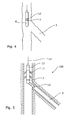
- Fig. 1 shows a downhole tool 1 for determining laterals 2 in a borehole wall 3 in an openhole well or a borehole casing 4 in a cased well.
- the downhole tool comprises a tool housing 5 extending along a longitudinal axis 6 and a plurality of sonic transceivers 7, each sonic transceiver transmitting sonic signals 8 from the housing 5 towards the borehole wall 3 or the borehole casing 4 and receiving sonic signals 8 reflected from the borehole wall 3 or borehole casing 4.
- Fig. 2 shows how the plurality of sonic transceivers 7 are arranged along the circumference of the tool housing 5 having a mutual distance and are capable of transmitting sonic signals 8 radially away from the tool housing 5 in a predefined angular segment 9 in an entire central angle of 360 degrees towards the borehole wall 3 or borehole casing 4.
- one transceiver 7 transmits a sonic signal 8 during a pulse time in the predefined angular segment 9 of that sonic transmitter 7, and during a subsequent echo time, one sonic transceiver 7 receives a reflected sonic signal 8 from the borehole wall 3 or borehole casing 4, and an absence of the received reflected sonic signal 8 during the subsequent echo time indicates the lateral 2. This is due to the fact that when there is no casing wall, the signal cannot be reflected and the signal fades.
- the sonic transceivers 7 may be arranged equidistantly along the circumference of the tool housing 5 to provide for symmetric measurements of the surrounding borehole 3 or borehole casing 4 and divide the annular space between the tool housing and the casing into predefined angular segments 9 of equal size.
- the transceivers may be receiving during the echo time to ensure that reflected sonic signals will always be received by at least one of the transceivers.
- the reflected signals may be received by a transceiver located far away from the transmitting transceiver, e.g. on the other side of the housing.
- Receiving with several transceivers may be done by simultaneous "listening" with several transceivers or by doing a series of measurements in which one transceiver is used to transmit signals and several transceivers are used to receive signals one at a time.
- transceivers may be used simultaneously to transmit signals.
- Physical conditions which may be appropriate for these types of measurements may be a situation in which the downhole tool 1 fills up nearly the entire annular space in the borehole. Under these conditions, it may be possible to do isolated measurements on several sides of the tool housing without interfering with the other measurements. In this way, measurement time may be drastically decreased, e.g. reduced by half by running two simultaneous series of measurements with transceivers placed diagonally on two sides of the tool housing 5.
- arrays of transceivers covering the entire central angle and even being resolved along the longitudinal axis of the tool may prospectively be advantageous and thereby also provide increased resolution in the determination of laterals.
- Fig. 3a shows a graphical cylindrical representation of the data coming from a corresponding downhole tool 1 shown in Fig. 3b for determining laterals 2 to visualise the position of the lateral 2 for the user.
- Each square on the cylindrical representation corresponds to one measurement at one given depth in the well.
- the downhole tool 1 is moved down through the well along the longitudinal axis 6.
- a series of measurements using the plurality of sonic transceivers 7 are made to investigate the surroundings of the downhole tool at that specific depth.
- Each of the series of measurements corresponds to one ring of squares on the cylindrical representation.
- Figs. 3c shows a graphical cylindrical representation of the data coming from a corresponding downhole tool 1 shown in Fig. 3d capable of determining laterals 2 with an increased resolution.
- the increased resolution may be obtained by placing a greater number of sonic transceivers along the circumference of the housing, which increases the resolution by decreasing the resolvable angular segments.
- the resolution may be increased along the longitudinal axis by moving the downhole tool in smaller steps along the longitudinal axis.
- Figs. 3e shows a graphical cylindrical representation of the data coming from a corresponding downhole tool 1 shown in Fig. 3f capable of determining laterals 2 with an even higher resolution.
- the increased resolution may be obtained by arranging arrays of transceivers such as an ultrasonic transducer array along the circumference of the tool housing.
- the resolution along the longitudinal axis may be equally increased by such arrays if two-dimensional arrays are arranged along the circumference of the tool housing providing resolution in both an angular direction and the longitudinal direction.
- Fig. 4 shows a downhole tool 1 in a borehole 3 comprising a lateral 2 without a borehole casing 4.
- the downhole tool further comprises a second plurality of sonic transceivers 10.
- Arranging a second plurality of sonic receivers 10 has the advantage of helping the redundancy of the system, such that the tool may still function in case of breakdown of the plurality of sonic transceivers.
- the second plurality of transceivers may provide a downhole tool 1 capable of determining a lateral faster, since two series of measurements may be made per one movement of the downhole tool. Adding even more pluralities of transceivers may further increase the redundancy of the tool, the resolution of a determination of a lateral and/or further increase a speed of the determination of a lateral.
- Fig. 5 shows a downhole system 100 for determination a laterals comprising a driving unit 11 for conveying the downhole tool 1 along the longitudinal axis deeper into the borehole or retracting the downhole tool 1 by a wireline 14.
- the downhole tool comprises a lateral locator tool 12 for engaging the lateral 2 after the position of the lateral 2 has been determined by the plurality of sonic transceivers 7.
- the downhole tool 1 may be forced to enter the lateral, thereby allowing any operational tools 13 comprised in the tool to enter the lateral 2 and perform the function of the operational tool 13 in the lateral 2.
- the operational tool 13 may be a logging tool, a key tool, a milling tool or a drilling tool.
- the system may further comprise a positioning tool using magnets and magnetometre, such as a casing collar locator.
- the downhole tool 1 is moved to a first position in the borehole for initialising the measurement for determining the position of a lateral 2.
- a series of pulse/echo measurements is conducted, i.e. transmitting a sonic signal referred to as a pulse and receiving the reflected sonic signal referred to as an echo.
- the pulse signal is initially transmitted by a sonic transceiver in a first angular segment 9 radially away from the downhole tool towards the borehole or borehole casing during a first pulse time.
- the sonic signal is reflected by the borehole or borehole casing back towards the downhole tool and recorded if the reflected sonic signal is received by a sonic transceiver during a first echo time. If no sonic signal is received during the first echo time, it may indicate that the downhole tool is opposite to a lateral in the borehole, since the transmitted sonic signal will be propagating into the lateral instead of being reflected by the borehole or borehole casing. The lack of reflected signal may also be due to the transceiver not being able to receive the reflected signal but if this is the case, it is confirmed in the subsequent measurement. If there continues to be no reflected signal in a certain angular segment 9, it indicates that a lateral is present as illustrated in Fig. 3c .
- the series of measurements continues in the first position by transmitting a new sonic signal by a neighbouring sonic transceiver in a second angular segment during a subsequent second pulse time, and in the same way the reflected sonic signal is recorded if a sonic transceiver receives the reflected signal during a second echo time.
- This type of pulse/echo measurements are continued at the first position until all angular segments along the entire circumference of the tool housing has been investigated.
- Different schemes may be set up for the sequence of pulsing transceivers, transmitting transceivers or receiving transceivers, duration of pulse time, duration of echo time, frequencies, amplitudes etc.
- each of the transceivers receiving the reflected signal may be used to record the reflected signal from one transmitting transceiver by either simultaneously "listening" with all transceivers or “listening” with only one transceiver during the echo time and transmitting a new pulse signal before listening with the next receiver etc.
- the downhole tool is moved to a second position in the borehole and a second series of pulse/echo measurements is conducted at the second position in the borehole.
- the position of the lateral may be determined from the absence of received reflected sonic signals in a subset of the measurements, since the absence of a reflected signal indicates that the measurement was conducted at a position opposite to the position of the lateral.
- the tool string 100 may effectively perform tasks in both the borehole 3 or main casing and a lateral 2 of the borehole 3 or the casing. Furthermore, by using a casing collar locator (CCL), the position of the lateral may be stored in a memory available for the user for future use, which will allow the user to revert to the same lateral faster on subsequent operations.
- CCL casing collar locator
Landscapes
- Engineering & Computer Science (AREA)
- Life Sciences & Earth Sciences (AREA)
- Physics & Mathematics (AREA)
- Geology (AREA)
- Mining & Mineral Resources (AREA)
- General Life Sciences & Earth Sciences (AREA)
- Environmental & Geological Engineering (AREA)
- Fluid Mechanics (AREA)
- Geochemistry & Mineralogy (AREA)
- Geophysics (AREA)
- Remote Sensing (AREA)
- Acoustics & Sound (AREA)
- General Physics & Mathematics (AREA)
- Electromagnetism (AREA)
- Mechanical Engineering (AREA)
- Geophysics And Detection Of Objects (AREA)
- Length Measuring Devices Characterised By Use Of Acoustic Means (AREA)
Priority Applications (15)
| Application Number | Priority Date | Filing Date | Title |
|---|---|---|---|
| EP11172151A EP2540957A1 (fr) | 2011-06-30 | 2011-06-30 | Outil d'extraction pour déterminer les dérivations de conduite |
| SA112330649A SA112330649B1 (ar) | 2011-06-30 | 2012-06-27 | أداة قاع بئر لتحديد التفرعات الجانبية |
| RU2014102495A RU2627778C2 (ru) | 2011-06-30 | 2012-06-27 | Скважинный инструмент для определения боковых ответвлений |
| BR112013033517-3A BR112013033517B1 (pt) | 2011-06-30 | 2012-06-27 | Ferramenta de fundo de poço para determinar laterais em uma parede de poço ou em um invólucro de poço, sistema de poço e método para determinar uma posição de uma lateral |
| EP12733030.6A EP2726702B1 (fr) | 2011-06-30 | 2012-06-27 | Outil d'extraction pour déterminer les dérivations de conduite |
| CN201280032456.5A CN103635657B (zh) | 2011-06-30 | 2012-06-27 | 用于测定支管的井下工具 |
| SA115360783A SA115360783B1 (ar) | 2011-06-30 | 2012-06-27 | أداة قاع بئر لتحديد التفرعات الجانبية |
| MX2013014576A MX365136B (es) | 2011-06-30 | 2012-06-27 | Herramienta del fondo de la perforación para determinar laterales. |
| PCT/EP2012/062419 WO2013000938A1 (fr) | 2011-06-30 | 2012-06-27 | Outil de fond de trou pour déterminer des dérivations de conduite |
| US14/130,224 US20140202242A1 (en) | 2011-06-30 | 2012-06-27 | Downhole tool for determining laterals |
| CA2840471A CA2840471C (fr) | 2011-06-30 | 2012-06-27 | Outil de fond de trou pour determiner des derivations de conduite |
| DK12733030.6T DK2726702T3 (da) | 2011-06-30 | 2012-06-27 | Brøndværktøj til bestemmelse af sideboringer |
| AU2012277926A AU2012277926B2 (en) | 2011-06-30 | 2012-06-27 | Downhole tool for determining laterals |
| MYPI2013004591A MY167174A (en) | 2011-06-30 | 2012-06-27 | Downhole tool for determining laterals |
| US16/872,737 US11542810B2 (en) | 2011-06-30 | 2020-05-12 | Downhole tool for determining laterals |
Applications Claiming Priority (1)
| Application Number | Priority Date | Filing Date | Title |
|---|---|---|---|
| EP11172151A EP2540957A1 (fr) | 2011-06-30 | 2011-06-30 | Outil d'extraction pour déterminer les dérivations de conduite |
Publications (1)
| Publication Number | Publication Date |
|---|---|
| EP2540957A1 true EP2540957A1 (fr) | 2013-01-02 |
Family
ID=46466461
Family Applications (2)
| Application Number | Title | Priority Date | Filing Date |
|---|---|---|---|
| EP11172151A Withdrawn EP2540957A1 (fr) | 2011-06-30 | 2011-06-30 | Outil d'extraction pour déterminer les dérivations de conduite |
| EP12733030.6A Active EP2726702B1 (fr) | 2011-06-30 | 2012-06-27 | Outil d'extraction pour déterminer les dérivations de conduite |
Family Applications After (1)
| Application Number | Title | Priority Date | Filing Date |
|---|---|---|---|
| EP12733030.6A Active EP2726702B1 (fr) | 2011-06-30 | 2012-06-27 | Outil d'extraction pour déterminer les dérivations de conduite |
Country Status (12)
| Country | Link |
|---|---|
| US (2) | US20140202242A1 (fr) |
| EP (2) | EP2540957A1 (fr) |
| CN (1) | CN103635657B (fr) |
| AU (1) | AU2012277926B2 (fr) |
| BR (1) | BR112013033517B1 (fr) |
| CA (1) | CA2840471C (fr) |
| DK (1) | DK2726702T3 (fr) |
| MX (1) | MX365136B (fr) |
| MY (1) | MY167174A (fr) |
| RU (1) | RU2627778C2 (fr) |
| SA (2) | SA115360783B1 (fr) |
| WO (1) | WO2013000938A1 (fr) |
Families Citing this family (9)
| Publication number | Priority date | Publication date | Assignee | Title |
|---|---|---|---|---|
| EP2990593A1 (fr) * | 2014-08-27 | 2016-03-02 | Welltec A/S | Système de transfert sans fil de fond de trou |
| CN105715254A (zh) * | 2014-12-02 | 2016-06-29 | 通用电气公司 | 用于确定钻杆位置的系统和方法 |
| WO2016209810A1 (fr) * | 2015-06-22 | 2016-12-29 | Saudi Arabian Oil Company | Systèmes, procédés et appareils de détection latérale de fond de trou mettant en œuvre des capteurs électromagnétiques |
| CN108016020B (zh) * | 2017-12-12 | 2023-10-24 | 河北天昱恒科技有限公司 | 塑料管自动检测装置 |
| AU2020370615A1 (en) * | 2019-10-25 | 2022-05-19 | Conocophillips Company | Systems and methods for analyzing casing bonding in a well using ultrasound velocity filtering |
| CN110672046A (zh) * | 2019-11-07 | 2020-01-10 | 淮南矿业(集团)有限责任公司 | 测井电缆长度校准方法 |
| US11530597B2 (en) | 2021-02-18 | 2022-12-20 | Saudi Arabian Oil Company | Downhole wireless communication |
| US11603756B2 (en) | 2021-03-03 | 2023-03-14 | Saudi Arabian Oil Company | Downhole wireless communication |
| US11619114B2 (en) | 2021-04-15 | 2023-04-04 | Saudi Arabian Oil Company | Entering a lateral branch of a wellbore with an assembly |
Citations (5)
| Publication number | Priority date | Publication date | Assignee | Title |
|---|---|---|---|---|
| US4867264A (en) * | 1986-09-17 | 1989-09-19 | Atlantic Richfield Company | Apparatus and method for investigating wellbores and the like |
| US5195588A (en) * | 1992-01-02 | 1993-03-23 | Schlumberger Technology Corporation | Apparatus and method for testing and repairing in a cased borehole |
| WO1998002638A1 (fr) * | 1996-07-17 | 1998-01-22 | Baker Hughes Incorporated | Dispositif et procede servant a effectuer des operations d'imagerie en fond de puits au niveau d'un emplacement dans des puits de sondage |
| WO1998012418A2 (fr) * | 1996-09-23 | 1998-03-26 | Intelligent Inspection Corporation Commonwealth Of Massachusetts | Outil de fond autonome pour gisement petrolifere |
| WO2008068561A1 (fr) * | 2006-12-07 | 2008-06-12 | Schlumberger Technology B.V. | Procédés et appareil pour guider un outil au fond d'un trou |
Family Cites Families (33)
| Publication number | Priority date | Publication date | Assignee | Title |
|---|---|---|---|---|
| US4022055A (en) * | 1974-12-02 | 1977-05-10 | Texaco Inc. | Pulse-echo method and system for testing wall thicknesses |
| US4587641A (en) * | 1984-02-07 | 1986-05-06 | Shell Oil Company | Downhole fracture analysis |
| US4814768A (en) * | 1987-09-28 | 1989-03-21 | The United States Of America As Represented By The United States Department Of Energy | Downhole pulse radar |
| US5164548A (en) * | 1988-02-08 | 1992-11-17 | Chevron Research And Technology Company | Method and apparatus for ultrasonic scanning of a borehole having improved sensor array and timing circuit |
| US4928269A (en) * | 1988-10-28 | 1990-05-22 | Schlumberger Technology Corporation | Determining impedance of material behind a casing in a borehole |
| US5678643A (en) | 1995-10-18 | 1997-10-21 | Halliburton Energy Services, Inc. | Acoustic logging while drilling tool to determine bed boundaries |
| US5996711A (en) * | 1997-04-14 | 1999-12-07 | Schlumberger Technology Corporation | Method and apparatus for locating indexing systems in a cased well and conducting multilateral branch operations |
| US6527067B1 (en) * | 1999-08-04 | 2003-03-04 | Bj Services Company | Lateral entry guidance system (LEGS) |
| CN1074501C (zh) * | 1999-09-30 | 2001-11-07 | 石油大学(华东) | 用超声脉冲反射法测量射孔孔眼深度的方法 |
| US6349768B1 (en) * | 1999-09-30 | 2002-02-26 | Schlumberger Technology Corporation | Method and apparatus for all multilateral well entry |
| US6891777B2 (en) * | 2002-06-19 | 2005-05-10 | Schlumberger Technology Corporation | Subsurface borehole evaluation and downhole tool position determination methods |
| US7258781B2 (en) | 2002-09-09 | 2007-08-21 | Clarity Filters Llc | Single-use long-life faucet-mounted water filtration devices |
| US20050039915A1 (en) * | 2003-08-19 | 2005-02-24 | Murray Douglas J. | Methods for navigating and for positioning devices in a borehole system |
| CN2685569Y (zh) * | 2004-03-09 | 2005-03-16 | 徐凌堂 | 超声波井径测量仪 |
| US20050259512A1 (en) * | 2004-05-24 | 2005-11-24 | Halliburton Energy Services, Inc. | Acoustic caliper with transducer array for improved off-center performance |
| US20060042792A1 (en) * | 2004-08-24 | 2006-03-02 | Connell Michael L | Methods and apparatus for locating a lateral wellbore |
| US7513302B2 (en) * | 2006-12-29 | 2009-04-07 | Schlumberger Technology Corporation | Apparatus for orienting a mule shoe to enter a previously-installed tubular in a lateral and method of use |
| EP2065553B1 (fr) * | 2007-11-30 | 2013-12-25 | Services Pétroliers Schlumberger | Système et procédé pour forer des trous de forage latéraux |
| US8201625B2 (en) * | 2007-12-26 | 2012-06-19 | Schlumberger Technology Corporation | Borehole imaging and orientation of downhole tools |
| US8117907B2 (en) * | 2008-12-19 | 2012-02-21 | Pathfinder Energy Services, Inc. | Caliper logging using circumferentially spaced and/or angled transducer elements |
| US8091633B2 (en) * | 2009-03-03 | 2012-01-10 | Saudi Arabian Oil Company | Tool for locating and plugging lateral wellbores |
| EP2317070A1 (fr) * | 2009-10-30 | 2011-05-04 | Welltec A/S | Système d'extraction |
| US20110080806A1 (en) * | 2009-12-08 | 2011-04-07 | Randy Allen Normann | System and method for geothermal acoustic interface |
| CN101761330B (zh) * | 2010-04-01 | 2013-11-06 | 山东科技大学 | 一种采用超声测井仪自身定向装置的超声测井系统 |
| US9766363B2 (en) * | 2010-07-30 | 2017-09-19 | Halliburton Energy Services, Inc | High resolution downhole imaging using signal conversion |
| DK2505766T3 (da) * | 2011-03-30 | 2013-11-11 | Welltec As | Brønddrivenhed der har en hydraulisk motor i et hjul |
| US9784874B2 (en) * | 2014-12-11 | 2017-10-10 | Baker Hughes Incorporated | Multi-beam phased array acoustic transducer operation for downhole applications |
| US9720121B2 (en) * | 2015-01-28 | 2017-08-01 | Baker Hughes Incorporated | Devices and methods for downhole acoustic imaging |
| GB2536420B (en) * | 2015-03-11 | 2018-02-28 | Schlumberger Holdings | Logging perforation flow in a wellbore |
| WO2016209810A1 (fr) * | 2015-06-22 | 2016-12-29 | Saudi Arabian Oil Company | Systèmes, procédés et appareils de détection latérale de fond de trou mettant en œuvre des capteurs électromagnétiques |
| US10739318B2 (en) * | 2017-04-19 | 2020-08-11 | Baker Hughes, A Ge Company, Llc | Detection system including sensors and method of operating such |
| US10876377B2 (en) * | 2018-06-29 | 2020-12-29 | Halliburton Energy Services, Inc. | Multi-lateral entry tool with independent control of functions |
| EP3862796B1 (fr) * | 2020-02-06 | 2024-08-21 | Services Pétroliers Schlumberger | Reconfiguration en temps réel d'opération de réseau à commande de phase |
-
2011
- 2011-06-30 EP EP11172151A patent/EP2540957A1/fr not_active Withdrawn
-
2012
- 2012-06-27 SA SA115360783A patent/SA115360783B1/ar unknown
- 2012-06-27 SA SA112330649A patent/SA112330649B1/ar unknown
- 2012-06-27 US US14/130,224 patent/US20140202242A1/en not_active Abandoned
- 2012-06-27 AU AU2012277926A patent/AU2012277926B2/en active Active
- 2012-06-27 DK DK12733030.6T patent/DK2726702T3/da active
- 2012-06-27 MY MYPI2013004591A patent/MY167174A/en unknown
- 2012-06-27 WO PCT/EP2012/062419 patent/WO2013000938A1/fr active Application Filing
- 2012-06-27 BR BR112013033517-3A patent/BR112013033517B1/pt active IP Right Grant
- 2012-06-27 EP EP12733030.6A patent/EP2726702B1/fr active Active
- 2012-06-27 CA CA2840471A patent/CA2840471C/fr not_active Expired - Fee Related
- 2012-06-27 RU RU2014102495A patent/RU2627778C2/ru active
- 2012-06-27 CN CN201280032456.5A patent/CN103635657B/zh not_active Expired - Fee Related
- 2012-06-27 MX MX2013014576A patent/MX365136B/es active IP Right Grant
-
2020
- 2020-05-12 US US16/872,737 patent/US11542810B2/en active Active
Patent Citations (5)
| Publication number | Priority date | Publication date | Assignee | Title |
|---|---|---|---|---|
| US4867264A (en) * | 1986-09-17 | 1989-09-19 | Atlantic Richfield Company | Apparatus and method for investigating wellbores and the like |
| US5195588A (en) * | 1992-01-02 | 1993-03-23 | Schlumberger Technology Corporation | Apparatus and method for testing and repairing in a cased borehole |
| WO1998002638A1 (fr) * | 1996-07-17 | 1998-01-22 | Baker Hughes Incorporated | Dispositif et procede servant a effectuer des operations d'imagerie en fond de puits au niveau d'un emplacement dans des puits de sondage |
| WO1998012418A2 (fr) * | 1996-09-23 | 1998-03-26 | Intelligent Inspection Corporation Commonwealth Of Massachusetts | Outil de fond autonome pour gisement petrolifere |
| WO2008068561A1 (fr) * | 2006-12-07 | 2008-06-12 | Schlumberger Technology B.V. | Procédés et appareil pour guider un outil au fond d'un trou |
Also Published As
| Publication number | Publication date |
|---|---|
| SA112330649B1 (ar) | 2016-03-13 |
| EP2726702B1 (fr) | 2017-07-26 |
| AU2012277926B2 (en) | 2015-05-07 |
| MX365136B (es) | 2019-05-24 |
| SA115360783B1 (ar) | 2017-06-01 |
| US20140202242A1 (en) | 2014-07-24 |
| AU2012277926A1 (en) | 2013-05-02 |
| RU2627778C2 (ru) | 2017-08-11 |
| DK2726702T3 (da) | 2017-11-06 |
| BR112013033517A2 (pt) | 2017-02-07 |
| CA2840471A1 (fr) | 2013-01-03 |
| CA2840471C (fr) | 2019-07-02 |
| CN103635657A (zh) | 2014-03-12 |
| BR112013033517B1 (pt) | 2020-09-15 |
| CN103635657B (zh) | 2018-05-01 |
| MX2013014576A (es) | 2014-03-21 |
| US11542810B2 (en) | 2023-01-03 |
| US20200270983A1 (en) | 2020-08-27 |
| RU2014102495A (ru) | 2015-08-10 |
| EP2726702A1 (fr) | 2014-05-07 |
| WO2013000938A1 (fr) | 2013-01-03 |
| MY167174A (en) | 2018-08-13 |
Similar Documents
| Publication | Publication Date | Title |
|---|---|---|
| US11542810B2 (en) | Downhole tool for determining laterals | |
| EP2702245B1 (fr) | Système transpondeur hybride pour détection longue portée et localisation 3d | |
| CA2694225C (fr) | Appareil de depistage de trepan et son procede | |
| US20100284250A1 (en) | Acoustic steering for borehole placement | |
| EP3004537B1 (fr) | Procédé et appareil de forage | |
| US9164185B2 (en) | Near-simultaneous acquisition for borehole seismic | |
| CA2692907C (fr) | Systeme et methode permettant de determiner l'emplacement d'un puits de forage | |
| MX2014008900A (es) | Robots de fondo de perforacion y metodos para utilizar los mismos. | |
| GB2452367A (en) | Obtaining an upwardly propagating data signal in wellbore communication system | |
| US9140816B2 (en) | Apparatus and method for determining formation anisotropy | |
| US11899155B2 (en) | System, method and apparatus for reduced water usage for fracturing hydrocarbon wells with three-dimensional imaging of the formation from a single borehole | |
| WO2021257133A1 (fr) | Balayage azimutal d'un puits de forage pour déterminer un état d'adhésivité du ciment et détecter/localiser une source de fuite | |
| CN108138564A (zh) | 包括低扭矩阀的泥浆脉冲遥测工具 | |
| US10890682B2 (en) | Method and system for imaging dipping structures | |
| NO20150858A1 (en) | Acoustic Data Compression Technique | |
| US11513247B2 (en) | Data acquisition systems | |
| CN107780849B (zh) | 隔水管单元系统、钻井系统和用于钻井系统的方法 | |
| WO2016094771A1 (fr) | Étude sismique de la terre | |
| US20240200429A1 (en) | Topological wellbore design | |
| Macpherson | Drilling trajectory optimization | |
| CA2806516A1 (fr) | Appareil de depistage de trepan et son procede | |
| US20160290125A1 (en) | Method for Determining Drilling Fluid Induced Fractures | |
| Muhleman Jr et al. | High technology marks another year of drilling progress |
Legal Events
| Date | Code | Title | Description |
|---|---|---|---|
| PUAI | Public reference made under article 153(3) epc to a published international application that has entered the european phase |
Free format text: ORIGINAL CODE: 0009012 |
|
| AK | Designated contracting states |
Kind code of ref document: A1 Designated state(s): AL AT BE BG CH CY CZ DE DK EE ES FI FR GB GR HR HU IE IS IT LI LT LU LV MC MK MT NL NO PL PT RO RS SE SI SK SM TR |
|
| AX | Request for extension of the european patent |
Extension state: BA ME |
|
| STAA | Information on the status of an ep patent application or granted ep patent |
Free format text: STATUS: THE APPLICATION IS DEEMED TO BE WITHDRAWN |
|
| 18D | Application deemed to be withdrawn |
Effective date: 20130703 |