EP2540953A1 - Board device to operate safely on ladders - Google Patents
Board device to operate safely on ladders Download PDFInfo
- Publication number
- EP2540953A1 EP2540953A1 EP12004825A EP12004825A EP2540953A1 EP 2540953 A1 EP2540953 A1 EP 2540953A1 EP 12004825 A EP12004825 A EP 12004825A EP 12004825 A EP12004825 A EP 12004825A EP 2540953 A1 EP2540953 A1 EP 2540953A1
- Authority
- EP
- European Patent Office
- Prior art keywords
- board device
- footboards
- hooks
- supporting frame
- order
- Prior art date
- Legal status (The legal status is an assumption and is not a legal conclusion. Google has not performed a legal analysis and makes no representation as to the accuracy of the status listed.)
- Granted
Links
- 230000009194 climbing Effects 0.000 claims description 4
- 239000002184 metal Substances 0.000 claims description 4
- 239000011888 foil Substances 0.000 claims description 3
- 230000006835 compression Effects 0.000 claims description 2
- 238000007906 compression Methods 0.000 claims description 2
- 238000003780 insertion Methods 0.000 claims description 2
- 230000037431 insertion Effects 0.000 claims description 2
- 238000009434 installation Methods 0.000 claims description 2
- 239000000463 material Substances 0.000 description 2
- 238000012986 modification Methods 0.000 description 2
- 230000004048 modification Effects 0.000 description 2
- 230000002860 competitive effect Effects 0.000 description 1
- 210000003127 knee Anatomy 0.000 description 1
- 210000002414 leg Anatomy 0.000 description 1
- 230000000670 limiting effect Effects 0.000 description 1
- 210000003141 lower extremity Anatomy 0.000 description 1
- 238000012423 maintenance Methods 0.000 description 1
- 238000004321 preservation Methods 0.000 description 1
- 230000000284 resting effect Effects 0.000 description 1
- 230000007306 turnover Effects 0.000 description 1
- 210000001364 upper extremity Anatomy 0.000 description 1
Images


Classifications
-
- E—FIXED CONSTRUCTIONS
- E06—DOORS, WINDOWS, SHUTTERS, OR ROLLER BLINDS IN GENERAL; LADDERS
- E06C—LADDERS
- E06C7/00—Component parts, supporting parts, or accessories
- E06C7/16—Platforms on, or for use on, ladders, e.g. liftable or lowerable platforms
Definitions
- the present invention relates to board device to operate safely on stairs, fixed and portable stairs, particularly for ladders.
- the present invention relates to a platform applicable to different types and sizes of ladders, for example leaning ladders used for building maintenance (power lines, facades preservation, or other).
- the object of the present invention is to eliminate the drawbacks noted above in known types of devices to operate on stairs, fixed and portable stairs, in particular on ladders, which can permit to secure an operator which is climbing on a ladder, stair or similar, and maneuver at a certain height which is dangerous forfalling.
- a board device to operate safely on stairs, particularly for ladders comprising:
- a board device to operate safely on stairs, particularly for ladders, according to the invention is generally designated by the reference numeral 1.
- One of the features of the device 1 is that it comprises a supporting frame 3 provided with hooks 4 for clamping to at least one step 5 of a stair 2, and a pair of footboards 6 placed side by side and arranged to be turned over with respect to developing direction of the supporting frame 3, in order that each one of the footboards is able to pass from a closed configuration to an open operating configuration, one independently from the other.
- the device pair of footboards 6 are connected to the frame 3 by means of rotational fulcrums distribution: pivots 7 and rotation hinges 8.
- the frame 3 comprises uprights 10 made for example of metal foils and provided, at the upper and lower extremities, of series of hooks 4.
- the hooks are arranged to be connected with two corresponding steps 5 of the stair 2 and to be linked with respective crosspieces 11 and 12.
- the crosspieces 11 and 12 are adjustable in length and the distance between the two series of hooks 4 is also adjustable in order to mount precisely the device 1 on stairs with different widths and which comprise steps placed at different distances.
- hooks 4 may be provided for anti-unthreading pins 18, for example metal split pins, inserted in a stable manner through holes 19 in order to close the step 5 inside of the hook 4.
- a threaded pressure screw 24 which passes through one of the holes 19 and intended to be mounted in compression against the step 5 for increasing the stability of the support of the device 1.
- the depth of the hooks 4, or the length of the transverse crosspiece 21, may also be adjustable to adapt the hook 4 in steps of different sizes.
- the two footboards 6 comprise, at one end, first rigid rods 15 which are arranged to be rotated about pivots 7 mounted on the supporting frame 3.
- the footboards 6 comprise also, at the opposite end, second slotted rods 9 which are hinged at rotation hinges 8 of said supporting frame 3 and which are arranged to slide, into a slot 13 of the second slotted rod 9, with respect to a pin 14.
- the pin 14 is integrally connected to the footboards 6.
- the footboards 6 comprise a first rigid part 16 and a movable driving part 17.
- This part 17 is articulated, with respect to the first part 16, about an axis 25, in order to oscillate toward the inner side of the stair (see the direction of arrow in Fig. 1 ).
- the part 17 allows the insertion of a foot of the operator during the climb and to gain spontaneously the position of alignment with the fixed section 16 when the device is in action.
- the risk that an operator may fall is further reduced, while the useable surface for foot placement remains the same, as it will be better specified below.
- the frame 3 In use, once the frame 3 is adjusted according to the size of the scale 2, it is attached to the steps 5 by means of the hooks 4, which are then closed by means of the anti-unthreading pins 18.
- the device 1 In the initial configuration, the device 1 is contained within the overall dimensions defined by the legs 23 of the ladder 2 ( Fig. 2 ).
- the footboards 6 have cross dimensions such as to be completely inside the space defined by the uprights 10 of the frame 3, possibly provided with notches 22 to allow the complete closure of the footboards 6 and to compensate for the excess in width due to the pins 14 of the footboards.
- this maneuver is particularly facilitated by the conformation of the movable section 17 of the footboards 6.
- the invention achieves the proposed aim and objectives and, in particular, the fact is stressed that the board device to operate safely on stairs, particularly for ladders, practically eliminates the risk of falls due to tripping on the footboard, because climbing the stair with the footboard in the closed configuration the operator can overpass the footboard itself in a normal manner, resting his feet on the steps of the ladder. At this point the operator can turn over the footboard using just one foot positioning the device in the operating configuration.
- the operator is able to rest his feet on both the footboards and to operate, in safety and comfort, at the desired level of the stair.
- the device is made of bent and welded metal foil, but it is understood that all the details may further be replaced by other technically equivalent elements.
- the materials used, as well as the dimensions, may any, according to requirements.
Landscapes
- Engineering & Computer Science (AREA)
- Mechanical Engineering (AREA)
- Ladders (AREA)
- Mechanical Control Devices (AREA)
- Forklifts And Lifting Vehicles (AREA)
- Rear-View Mirror Devices That Are Mounted On The Exterior Of The Vehicle (AREA)
Abstract
- a supporting frame (3) provided with hooks (4) for clamping to at least one step (5) of a stair (2), and
- a pair of footboards (6) placed side by side and arranged to be turned over with respect to said supporting frame
Description
- The present invention relates to board device to operate safely on stairs, fixed and portable stairs, particularly for ladders.
- Principally, the present invention relates to a platform applicable to different types and sizes of ladders, for example leaning ladders used for building maintenance (power lines, facades preservation, or other).
- At the state of the art, there are known stairs provided with footboards or platforms, with a fixed structure. These kinds of devices oblige the operator, who is climbing on the ladder, to pass over the footboard of the ladder.
- This is due to the fact that these platforms protrude from the natural ascent line of the stairs because of their fixed form, and they therefore represent a major obstacle for workers.
- In fact, it is required for the operator to bend his body back, to avoid bumping into the platform with his knees, increasing the risk of falling during a phase which is already difficult itself.
- The object of the present invention is to eliminate the drawbacks noted above in known types of devices to operate on stairs, fixed and portable stairs, in particular on ladders, which can permit to secure an operator which is climbing on a ladder, stair or similar, and maneuver at a certain height which is dangerous forfalling.
- This aim and these and other objectives which will become better apparent hereinafter, are achieved by a board device to operate safely on stairs, particularly for ladders, comprising:
- a supporting frame provided with hooks for clamping to at least one step of a stair, and
- a pair of footboards placed side by side and arranged to be turned over with respect to said supporting frame in order that each one of the footboards passes independently from a closed configuration to an open operating configuration.
- Further characteristics and advantages of the invention will become better apparent from the following detailed description of a preferred but not exclusive embodiment of the board device to operate safely on stairs, particularly for ladders, illustrated only by way of non-limitative example with the aid of the accompanying drawings wherein:
-
Figure 1 represents a portion of the board device in operating configuration, in perspective view; -
Figure 2 represents, in a perspective view, a portion of the device of the preceding Figure, applied to a ladder, in the initial closed configuration; -
Figure 3 shows a portion of the device in semi-open position; -
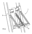
Figure 4 shows a portion of the device, completely opened, in the final configuration. - With reference to the figures, a board device to operate safely on stairs, particularly for ladders, according to the invention, is generally designated by the
reference numeral 1. - One of the features of the
device 1 is that it comprises a supporting frame 3 provided withhooks 4 for clamping to at least onestep 5 of astair 2, and a pair offootboards 6 placed side by side and arranged to be turned over with respect to developing direction of the supporting frame 3, in order that each one of the footboards is able to pass from a closed configuration to an open operating configuration, one independently from the other. - The device pair of
footboards 6 are connected to the frame 3 by means of rotational fulcrums distribution: pivots 7 and rotation hinges 8. - In particular, the frame 3 comprises
uprights 10 made for example of metal foils and provided, at the upper and lower extremities, of series ofhooks 4. The hooks are arranged to be connected with twocorresponding steps 5 of thestair 2 and to be linked withrespective crosspieces - Preferably, the
crosspieces hooks 4 is also adjustable in order to mount precisely thedevice 1 on stairs with different widths and which comprise steps placed at different distances. - Moreover, in correspondence of the
hooks 4 may be provided foranti-unthreading pins 18, for example metal split pins, inserted in a stable manner throughholes 19 in order to close thestep 5 inside of thehook 4. - Preferably, there are provided
additional holes 19 in order to adjust the distance between thepins 18 and thehooks 4, by means of atransverse crosspiece 21, depending on the size of thestep 5, and thus it may be avoided the option of an excessive possibility of movement of the step inside of thehooks 4. - In addition, it may be provided a threaded
pressure screw 24 which passes through one of theholes 19 and intended to be mounted in compression against thestep 5 for increasing the stability of the support of thedevice 1. - In a preferred embodiment, the depth of the
hooks 4, or the length of thetransverse crosspiece 21, may also be adjustable to adapt thehook 4 in steps of different sizes. - According to the present invention, the two
footboards 6 comprise, at one end, firstrigid rods 15 which are arranged to be rotated about pivots 7 mounted on the supporting frame 3. Thefootboards 6 comprise also, at the opposite end, second slotted rods 9 which are hinged at rotation hinges 8 of said supporting frame 3 and which are arranged to slide, into aslot 13 of the second slotted rod 9, with respect to apin 14. Thepin 14 is integrally connected to thefootboards 6. - Preferably, the
footboards 6 comprise a firstrigid part 16 and amovable driving part 17. Thispart 17 is articulated, with respect to thefirst part 16, about anaxis 25, in order to oscillate toward the inner side of the stair (see the direction of arrow inFig. 1 ). - Advantageously, according to this solution, the
part 17 allows the insertion of a foot of the operator during the climb and to gain spontaneously the position of alignment with thefixed section 16 when the device is in action. Thus, the risk that an operator may fall is further reduced, while the useable surface for foot placement remains the same, as it will be better specified below. - In use, once the frame 3 is adjusted according to the size of the
scale 2, it is attached to thesteps 5 by means of thehooks 4, which are then closed by means of theanti-unthreading pins 18. In the initial configuration, thedevice 1 is contained within the overall dimensions defined by thelegs 23 of the ladder 2 (Fig. 2 ). - Advantageously, the
footboards 6 have cross dimensions such as to be completely inside the space defined by theuprights 10 of the frame 3, possibly provided withnotches 22 to allow the complete closure of thefootboards 6 and to compensate for the excess in width due to thepins 14 of the footboards. - With the device in the configuration of
Figure 1 , the operator can climb the ladder and pass without any difficulty the point of installation of the device, with the possibility to rest feet onstep 5 of the lower connection. - As mentioned above, this maneuver is particularly facilitated by the conformation of the
movable section 17 of thefootboards 6. - To break down the footboards, the operator must only raise one of two feet up, firmly remaining into abutment with the other foot and then pull down one of the two footboards as shown in
Figure 3 . - At this point, it will be sufficient to place only one foot on the lower footboard and safely perform the same maneuver pulling down the second footboard to obtain the open configuration of
Figure 4 . - From what has been described above it is therefore evident that the invention achieves the proposed aim and objectives and, in particular, the fact is stressed that the board device to operate safely on stairs, particularly for ladders, practically eliminates the risk of falls due to tripping on the footboard, because climbing the stair with the footboard in the closed configuration the operator can overpass the footboard itself in a normal manner, resting his feet on the steps of the ladder. At this point the operator can turn over the footboard using just one foot positioning the device in the operating configuration.
- In this configuration, the operator is able to rest his feet on both the footboards and to operate, in safety and comfort, at the desired level of the stair.
- In a preferred embodiment, the device is made of bent and welded metal foil, but it is understood that all the details may further be replaced by other technically equivalent elements.
- In practice, the materials used, as well as the dimensions, may any, according to requirements.
- Moreover, the employment of means easily available commercially and the usage of common materials make the device economically competitive.
- Although the disclosed embodiments have been fully described with reference to the accompanying drawings, it is to be noted that various changes and modifications will become apparent to those skilled in the art. Such changes and modifications are to be understood as being included within the scope of the disclosed embodiments as defined by the appended claims
- The disclosure in Italian Patent Applications No.
RM2011U000114 - Where technical features mentioned in any claim are followed by reference numbers, those reference numbers have been included for the sole purpose of increasing the intelligibility of the claims and accordingly, such reference numbers do not have any limiting effect on the interpretation of each element identified by way of example by such reference numbers.
Claims (12)
- A board device to operate safely on stairs, particularly for ladders, comprising:- a supporting frame (3) provided with hooks (4) for clamping to at least one step (5) of a stair (2), and- a pair of footboards (6) placed side by side and arranged to be turned over with respect to said supporting frame (3) in order that each one of said footboards (6) passes independently from a closed configuration to an open operating configuration.
- The board device according to claim 1, wherein said supporting frame (3) is provided with two series of said hooks (4) arranged to be connected to two corresponding steps (5) of the stair (2) and connected by respective crosspieces (11, 12) .
- The board device according to claim 1 or 2, wherein the distance between said two series of hooks (4) and/or the length of said crosspieces (11, 12) are adjustable in order to permit the installation of the board device (1) itself in stairs of different sizes.
- The board device according to one of the preceding claims, wherein said footboards (6) are articulated with respect to the uprights (10) of said supporting frame (3), in the closed configuration said footboards (6) being contained within the overall dimensions defined by said uprights (10).
- The board device according to one of the preceding claims, wherein said hooks (4) are provided with anti-unthreading pins (18).
- The board device according to claim 5, wherein said anti-unthreading pins (18) are arranged to be mounted at an adjustable distance from said hooks (4) by means of a transverse crosspiece (21), in order to close any steps (5) of different sizes inside said hook (4).
- The board device according to one of the preceding claims, wherein said hooks (4) are provided with at least one pressure screw (24) intended to be screwed, by means of compression, against said step (5) to increase the stability of support of the board device (1) towards said stair (2).
- The board device according to one of the preceding claims, wherein the depth of said hooks (4), or the length of said transverse crosspiece (21), is adjustable to fit the hook (4) with steps of different sizes.
- The board device according to one of the preceding claims, wherein said footboards (6) comprise, at one end, first rigid rods (15) which are arranged to be rotated about pivots (7) mounted on said supporting frame (3) and, at the opposite end, comprise second slotted rods (9) which are hinged at rotation hinges (8) of said supporting frame (3) and which re arranged to slide, into a slot (13) of said second slotted rod (9), with respect to a pin (14), said pin (14) being integrally connected with said footboards (6).
- The board device according to one of the preceding claims, wherein said footboards (6) are provided with a movable driving part (17) in order to facilitate the insertion of a foot of the operator during the climbing and the support of the foot on said step (5), in said closed configuration.
- The board device according to one of the preceding claims, wherein said uprights (10) are provided with notches (22) in order to lodge the excess width of said pins (14) of said footboards (6).
- The board device according to one of the preceding claims, characterized by the fact that it is made of bent and welded metal foil.
Applications Claiming Priority (1)
| Application Number | Priority Date | Filing Date | Title |
|---|---|---|---|
| IT000114U ITRM20110114U1 (en) | 2011-06-28 | 2011-06-28 | FOOTREST DEVICE FOR SAFE OPERATION ON SCALES. |
Publications (2)
| Publication Number | Publication Date |
|---|---|
| EP2540953A1 true EP2540953A1 (en) | 2013-01-02 |
| EP2540953B1 EP2540953B1 (en) | 2021-01-27 |
Family
ID=44900016
Family Applications (1)
| Application Number | Title | Priority Date | Filing Date |
|---|---|---|---|
| EP12004825.1A Active EP2540953B1 (en) | 2011-06-28 | 2012-06-27 | Board device to operate safely on ladders |
Country Status (2)
| Country | Link |
|---|---|
| EP (1) | EP2540953B1 (en) |
| IT (1) | ITRM20110114U1 (en) |
Citations (4)
| Publication number | Priority date | Publication date | Assignee | Title |
|---|---|---|---|---|
| FR2367182A1 (en) * | 1976-10-11 | 1978-05-05 | Soell Ind Schmiede | SERVICE PLATFORM TO BE FIXED ON A LADDER |
| DE9202142U1 (en) * | 1992-02-19 | 1992-04-16 | Fahrleitungsbau Gmbh, 4300 Essen | Foot platform on a ladder with rungs, especially a fixed building ladder |
| US6109392A (en) * | 1999-09-09 | 2000-08-29 | Merrick; Harry G. | Split platform ladder stand |
| US7845469B1 (en) * | 2006-07-20 | 2010-12-07 | Butler David C | Ladder caddy |
Family Cites Families (1)
| Publication number | Priority date | Publication date | Assignee | Title |
|---|---|---|---|---|
| JP4476044B2 (en) * | 2004-06-29 | 2010-06-09 | 旭化成ホームズ株式会社 | Ladder scaffolding |
-
2011
- 2011-06-28 IT IT000114U patent/ITRM20110114U1/en unknown
-
2012
- 2012-06-27 EP EP12004825.1A patent/EP2540953B1/en active Active
Patent Citations (4)
| Publication number | Priority date | Publication date | Assignee | Title |
|---|---|---|---|---|
| FR2367182A1 (en) * | 1976-10-11 | 1978-05-05 | Soell Ind Schmiede | SERVICE PLATFORM TO BE FIXED ON A LADDER |
| DE9202142U1 (en) * | 1992-02-19 | 1992-04-16 | Fahrleitungsbau Gmbh, 4300 Essen | Foot platform on a ladder with rungs, especially a fixed building ladder |
| US6109392A (en) * | 1999-09-09 | 2000-08-29 | Merrick; Harry G. | Split platform ladder stand |
| US7845469B1 (en) * | 2006-07-20 | 2010-12-07 | Butler David C | Ladder caddy |
Also Published As
| Publication number | Publication date |
|---|---|
| EP2540953B1 (en) | 2021-01-27 |
| ITRM20110114U1 (en) | 2012-12-29 |
Similar Documents
| Publication | Publication Date | Title |
|---|---|---|
| AU2018202466B2 (en) | Grating | |
| ES2625338T3 (en) | Climbing equipment with folding platform and railing | |
| US11299933B2 (en) | Steps forming a spiral staircase for a treestand | |
| US10064403B2 (en) | Safety rail | |
| PT1861564E (en) | Working platform | |
| EP2540953A1 (en) | Board device to operate safely on ladders | |
| US20130001014A1 (en) | Method of stabilizing a portable ladder | |
| EP3596297A1 (en) | Ladder system for trench shoring | |
| KR102236223B1 (en) | Anti-slip device for ladders | |
| EP2078819A1 (en) | Stepladder with folding platform and separating support legs | |
| EP3109395A1 (en) | Ladder, in particular a step ladder with prevention against sinking | |
| KR20210022205A (en) | Ladder with elevating foot plate | |
| EP3607164B1 (en) | Ladder with telescopic stabilizer | |
| KR20110002720U (en) | Uma ladder for aerial work | |
| KR102180074B1 (en) | Foot protection device for folding ladder | |
| KR101608803B1 (en) | Width adjustment for ladder | |
| DE202014002891U1 (en) | Fold-out traverse for stand widening of ladders for stepless leveling with the additional functions of a spar extension and a wall spacer | |
| KR20180000801U (en) | Safety foothold for ladder | |
| US12264541B1 (en) | Ladder support apparatus, system, and method | |
| KR101215062B1 (en) | Supporting device for ladder | |
| KR20110047913A (en) | Frame reinforcement structure of ladder | |
| KR20190131681A (en) | Safety smart ladder for the maximize to the ease of movement and storage | |
| KR200461587Y1 (en) | safety bar assembly of work table | |
| US1033389A (en) | Scaffold. | |
| WO2017139722A1 (en) | Apparatus and method for securing a ladder |
Legal Events
| Date | Code | Title | Description |
|---|---|---|---|
| PUAI | Public reference made under article 153(3) epc to a published international application that has entered the european phase |
Free format text: ORIGINAL CODE: 0009012 |
|
| AK | Designated contracting states |
Kind code of ref document: A1 Designated state(s): AL AT BE BG CH CY CZ DE DK EE ES FI FR GB GR HR HU IE IS IT LI LT LU LV MC MK MT NL NO PL PT RO RS SE SI SK SM TR |
|
| AX | Request for extension of the european patent |
Extension state: BA ME |
|
| RBV | Designated contracting states (corrected) |
Designated state(s): AL AT BE BG CH CY CZ DE DK EE ES FI FR GB GR HR HU IE IS IT LI LT LU LV MC MK MT NL NO PL PT RO RS SE SI SK SM TR |
|
| 17P | Request for examination filed |
Effective date: 20130620 |
|
| 17Q | First examination report despatched |
Effective date: 20160411 |
|
| STAA | Information on the status of an ep patent application or granted ep patent |
Free format text: STATUS: EXAMINATION IS IN PROGRESS |
|
| GRAP | Despatch of communication of intention to grant a patent |
Free format text: ORIGINAL CODE: EPIDOSNIGR1 |
|
| STAA | Information on the status of an ep patent application or granted ep patent |
Free format text: STATUS: GRANT OF PATENT IS INTENDED |
|
| INTG | Intention to grant announced |
Effective date: 20200717 |
|
| GRAS | Grant fee paid |
Free format text: ORIGINAL CODE: EPIDOSNIGR3 |
|
| GRAA | (expected) grant |
Free format text: ORIGINAL CODE: 0009210 |
|
| STAA | Information on the status of an ep patent application or granted ep patent |
Free format text: STATUS: THE PATENT HAS BEEN GRANTED |
|
| AK | Designated contracting states |
Kind code of ref document: B1 Designated state(s): AL AT BE BG CH CY CZ DE DK EE ES FI FR GB GR HR HU IE IS IT LI LT LU LV MC MK MT NL NO PL PT RO RS SE SI SK SM TR |
|
| REG | Reference to a national code |
Ref country code: GB Ref legal event code: FG4D |
|
| REG | Reference to a national code |
Ref country code: CH Ref legal event code: EP |
|
| REG | Reference to a national code |
Ref country code: AT Ref legal event code: REF Ref document number: 1358499 Country of ref document: AT Kind code of ref document: T Effective date: 20210215 |
|
| REG | Reference to a national code |
Ref country code: IE Ref legal event code: FG4D |
|
| REG | Reference to a national code |
Ref country code: DE Ref legal event code: R096 Ref document number: 602012074260 Country of ref document: DE |
|
| REG | Reference to a national code |
Ref country code: CH Ref legal event code: NV Representative=s name: LUMI IP GMBH, CH |
|
| REG | Reference to a national code |
Ref country code: NL Ref legal event code: MP Effective date: 20210127 |
|
| REG | Reference to a national code |
Ref country code: LT Ref legal event code: MG9D |
|
| REG | Reference to a national code |
Ref country code: AT Ref legal event code: MK05 Ref document number: 1358499 Country of ref document: AT Kind code of ref document: T Effective date: 20210127 |
|
| PG25 | Lapsed in a contracting state [announced via postgrant information from national office to epo] |
Ref country code: FI Free format text: LAPSE BECAUSE OF FAILURE TO SUBMIT A TRANSLATION OF THE DESCRIPTION OR TO PAY THE FEE WITHIN THE PRESCRIBED TIME-LIMIT Effective date: 20210127 Ref country code: GR Free format text: LAPSE BECAUSE OF FAILURE TO SUBMIT A TRANSLATION OF THE DESCRIPTION OR TO PAY THE FEE WITHIN THE PRESCRIBED TIME-LIMIT Effective date: 20210428 Ref country code: HR Free format text: LAPSE BECAUSE OF FAILURE TO SUBMIT A TRANSLATION OF THE DESCRIPTION OR TO PAY THE FEE WITHIN THE PRESCRIBED TIME-LIMIT Effective date: 20210127 Ref country code: PT Free format text: LAPSE BECAUSE OF FAILURE TO SUBMIT A TRANSLATION OF THE DESCRIPTION OR TO PAY THE FEE WITHIN THE PRESCRIBED TIME-LIMIT Effective date: 20210527 Ref country code: LT Free format text: LAPSE BECAUSE OF FAILURE TO SUBMIT A TRANSLATION OF THE DESCRIPTION OR TO PAY THE FEE WITHIN THE PRESCRIBED TIME-LIMIT Effective date: 20210127 Ref country code: NO Free format text: LAPSE BECAUSE OF FAILURE TO SUBMIT A TRANSLATION OF THE DESCRIPTION OR TO PAY THE FEE WITHIN THE PRESCRIBED TIME-LIMIT Effective date: 20210427 Ref country code: NL Free format text: LAPSE BECAUSE OF FAILURE TO SUBMIT A TRANSLATION OF THE DESCRIPTION OR TO PAY THE FEE WITHIN THE PRESCRIBED TIME-LIMIT Effective date: 20210127 Ref country code: BG Free format text: LAPSE BECAUSE OF FAILURE TO SUBMIT A TRANSLATION OF THE DESCRIPTION OR TO PAY THE FEE WITHIN THE PRESCRIBED TIME-LIMIT Effective date: 20210427 |
|
| PG25 | Lapsed in a contracting state [announced via postgrant information from national office to epo] |
Ref country code: RS Free format text: LAPSE BECAUSE OF FAILURE TO SUBMIT A TRANSLATION OF THE DESCRIPTION OR TO PAY THE FEE WITHIN THE PRESCRIBED TIME-LIMIT Effective date: 20210127 Ref country code: PL Free format text: LAPSE BECAUSE OF FAILURE TO SUBMIT A TRANSLATION OF THE DESCRIPTION OR TO PAY THE FEE WITHIN THE PRESCRIBED TIME-LIMIT Effective date: 20210127 Ref country code: LV Free format text: LAPSE BECAUSE OF FAILURE TO SUBMIT A TRANSLATION OF THE DESCRIPTION OR TO PAY THE FEE WITHIN THE PRESCRIBED TIME-LIMIT Effective date: 20210127 Ref country code: AT Free format text: LAPSE BECAUSE OF FAILURE TO SUBMIT A TRANSLATION OF THE DESCRIPTION OR TO PAY THE FEE WITHIN THE PRESCRIBED TIME-LIMIT Effective date: 20210127 Ref country code: SE Free format text: LAPSE BECAUSE OF FAILURE TO SUBMIT A TRANSLATION OF THE DESCRIPTION OR TO PAY THE FEE WITHIN THE PRESCRIBED TIME-LIMIT Effective date: 20210127 |
|
| PG25 | Lapsed in a contracting state [announced via postgrant information from national office to epo] |
Ref country code: IS Free format text: LAPSE BECAUSE OF FAILURE TO SUBMIT A TRANSLATION OF THE DESCRIPTION OR TO PAY THE FEE WITHIN THE PRESCRIBED TIME-LIMIT Effective date: 20210527 |
|
| REG | Reference to a national code |
Ref country code: DE Ref legal event code: R097 Ref document number: 602012074260 Country of ref document: DE |
|
| PG25 | Lapsed in a contracting state [announced via postgrant information from national office to epo] |
Ref country code: EE Free format text: LAPSE BECAUSE OF FAILURE TO SUBMIT A TRANSLATION OF THE DESCRIPTION OR TO PAY THE FEE WITHIN THE PRESCRIBED TIME-LIMIT Effective date: 20210127 Ref country code: CZ Free format text: LAPSE BECAUSE OF FAILURE TO SUBMIT A TRANSLATION OF THE DESCRIPTION OR TO PAY THE FEE WITHIN THE PRESCRIBED TIME-LIMIT Effective date: 20210127 Ref country code: SM Free format text: LAPSE BECAUSE OF FAILURE TO SUBMIT A TRANSLATION OF THE DESCRIPTION OR TO PAY THE FEE WITHIN THE PRESCRIBED TIME-LIMIT Effective date: 20210127 |
|
| PG25 | Lapsed in a contracting state [announced via postgrant information from national office to epo] |
Ref country code: RO Free format text: LAPSE BECAUSE OF FAILURE TO SUBMIT A TRANSLATION OF THE DESCRIPTION OR TO PAY THE FEE WITHIN THE PRESCRIBED TIME-LIMIT Effective date: 20210127 Ref country code: ES Free format text: LAPSE BECAUSE OF FAILURE TO SUBMIT A TRANSLATION OF THE DESCRIPTION OR TO PAY THE FEE WITHIN THE PRESCRIBED TIME-LIMIT Effective date: 20210127 Ref country code: DK Free format text: LAPSE BECAUSE OF FAILURE TO SUBMIT A TRANSLATION OF THE DESCRIPTION OR TO PAY THE FEE WITHIN THE PRESCRIBED TIME-LIMIT Effective date: 20210127 Ref country code: SK Free format text: LAPSE BECAUSE OF FAILURE TO SUBMIT A TRANSLATION OF THE DESCRIPTION OR TO PAY THE FEE WITHIN THE PRESCRIBED TIME-LIMIT Effective date: 20210127 |
|
| PLBE | No opposition filed within time limit |
Free format text: ORIGINAL CODE: 0009261 |
|
| STAA | Information on the status of an ep patent application or granted ep patent |
Free format text: STATUS: NO OPPOSITION FILED WITHIN TIME LIMIT |
|
| 26N | No opposition filed |
Effective date: 20211028 |
|
| PG25 | Lapsed in a contracting state [announced via postgrant information from national office to epo] |
Ref country code: AL Free format text: LAPSE BECAUSE OF FAILURE TO SUBMIT A TRANSLATION OF THE DESCRIPTION OR TO PAY THE FEE WITHIN THE PRESCRIBED TIME-LIMIT Effective date: 20210127 Ref country code: MC Free format text: LAPSE BECAUSE OF FAILURE TO SUBMIT A TRANSLATION OF THE DESCRIPTION OR TO PAY THE FEE WITHIN THE PRESCRIBED TIME-LIMIT Effective date: 20210127 |
|
| GBPC | Gb: european patent ceased through non-payment of renewal fee |
Effective date: 20210627 |
|
| PG25 | Lapsed in a contracting state [announced via postgrant information from national office to epo] |
Ref country code: SI Free format text: LAPSE BECAUSE OF FAILURE TO SUBMIT A TRANSLATION OF THE DESCRIPTION OR TO PAY THE FEE WITHIN THE PRESCRIBED TIME-LIMIT Effective date: 20210127 |
|
| PG25 | Lapsed in a contracting state [announced via postgrant information from national office to epo] |
Ref country code: LU Free format text: LAPSE BECAUSE OF NON-PAYMENT OF DUE FEES Effective date: 20210627 |
|
| PG25 | Lapsed in a contracting state [announced via postgrant information from national office to epo] |
Ref country code: IE Free format text: LAPSE BECAUSE OF NON-PAYMENT OF DUE FEES Effective date: 20210627 Ref country code: GB Free format text: LAPSE BECAUSE OF NON-PAYMENT OF DUE FEES Effective date: 20210627 |
|
| PG25 | Lapsed in a contracting state [announced via postgrant information from national office to epo] |
Ref country code: IS Free format text: LAPSE BECAUSE OF FAILURE TO SUBMIT A TRANSLATION OF THE DESCRIPTION OR TO PAY THE FEE WITHIN THE PRESCRIBED TIME-LIMIT Effective date: 20210527 |
|
| PG25 | Lapsed in a contracting state [announced via postgrant information from national office to epo] |
Ref country code: IT Free format text: LAPSE BECAUSE OF NON-PAYMENT OF DUE FEES Effective date: 20210627 |
|
| PGFP | Annual fee paid to national office [announced via postgrant information from national office to epo] |
Ref country code: DE Payment date: 20220630 Year of fee payment: 11 |
|
| PGFP | Annual fee paid to national office [announced via postgrant information from national office to epo] |
Ref country code: FR Payment date: 20220706 Year of fee payment: 11 Ref country code: BE Payment date: 20220707 Year of fee payment: 11 |
|
| PGFP | Annual fee paid to national office [announced via postgrant information from national office to epo] |
Ref country code: CH Payment date: 20221201 Year of fee payment: 11 |
|
| PG25 | Lapsed in a contracting state [announced via postgrant information from national office to epo] |
Ref country code: HU Free format text: LAPSE BECAUSE OF FAILURE TO SUBMIT A TRANSLATION OF THE DESCRIPTION OR TO PAY THE FEE WITHIN THE PRESCRIBED TIME-LIMIT; INVALID AB INITIO Effective date: 20120627 Ref country code: CY Free format text: LAPSE BECAUSE OF FAILURE TO SUBMIT A TRANSLATION OF THE DESCRIPTION OR TO PAY THE FEE WITHIN THE PRESCRIBED TIME-LIMIT Effective date: 20210127 |
|
| REG | Reference to a national code |
Ref country code: DE Ref legal event code: R119 Ref document number: 602012074260 Country of ref document: DE |
|
| REG | Reference to a national code |
Ref country code: CH Ref legal event code: PL |
|
| REG | Reference to a national code |
Ref country code: BE Ref legal event code: MM Effective date: 20230630 |
|
| PG25 | Lapsed in a contracting state [announced via postgrant information from national office to epo] |
Ref country code: MK Free format text: LAPSE BECAUSE OF FAILURE TO SUBMIT A TRANSLATION OF THE DESCRIPTION OR TO PAY THE FEE WITHIN THE PRESCRIBED TIME-LIMIT Effective date: 20210127 Ref country code: DE Free format text: LAPSE BECAUSE OF NON-PAYMENT OF DUE FEES Effective date: 20240103 Ref country code: CH Free format text: LAPSE BECAUSE OF NON-PAYMENT OF DUE FEES Effective date: 20230630 |
|
| PG25 | Lapsed in a contracting state [announced via postgrant information from national office to epo] |
Ref country code: FR Free format text: LAPSE BECAUSE OF NON-PAYMENT OF DUE FEES Effective date: 20230630 Ref country code: BE Free format text: LAPSE BECAUSE OF NON-PAYMENT OF DUE FEES Effective date: 20230630 |
|
| PG25 | Lapsed in a contracting state [announced via postgrant information from national office to epo] |
Ref country code: TR Free format text: LAPSE BECAUSE OF FAILURE TO SUBMIT A TRANSLATION OF THE DESCRIPTION OR TO PAY THE FEE WITHIN THE PRESCRIBED TIME-LIMIT Effective date: 20210127 |
|
| PG25 | Lapsed in a contracting state [announced via postgrant information from national office to epo] |
Ref country code: MT Free format text: LAPSE BECAUSE OF FAILURE TO SUBMIT A TRANSLATION OF THE DESCRIPTION OR TO PAY THE FEE WITHIN THE PRESCRIBED TIME-LIMIT Effective date: 20210127 |