EP2540918A1 - Hygiene device with improved consumption for sanitary appliances - Google Patents
Hygiene device with improved consumption for sanitary appliances Download PDFInfo
- Publication number
- EP2540918A1 EP2540918A1 EP12174344A EP12174344A EP2540918A1 EP 2540918 A1 EP2540918 A1 EP 2540918A1 EP 12174344 A EP12174344 A EP 12174344A EP 12174344 A EP12174344 A EP 12174344A EP 2540918 A1 EP2540918 A1 EP 2540918A1
- Authority
- EP
- European Patent Office
- Prior art keywords
- flat
- solid block
- perforated plate
- pegs
- plate
- Prior art date
- Legal status (The legal status is an assumption and is not a legal conclusion. Google has not performed a legal analysis and makes no representation as to the accuracy of the status listed.)
- Granted
Links
Images


Classifications
-
- E—FIXED CONSTRUCTIONS
- E03—WATER SUPPLY; SEWERAGE
- E03D—WATER-CLOSETS OR URINALS WITH FLUSHING DEVICES; FLUSHING VALVES THEREFOR
- E03D9/00—Sanitary or other accessories for lavatories ; Devices for cleaning or disinfecting the toilet room or the toilet bowl; Devices for eliminating smells
- E03D9/02—Devices adding a disinfecting, deodorising, or cleaning agent to the water while flushing
- E03D9/022—Devices adding a disinfecting, deodorising, or cleaning agent to the water while flushing consisting of solid substances introduced in the bowl or the supply line
-
- E—FIXED CONSTRUCTIONS
- E03—WATER SUPPLY; SEWERAGE
- E03D—WATER-CLOSETS OR URINALS WITH FLUSHING DEVICES; FLUSHING VALVES THEREFOR
- E03D9/00—Sanitary or other accessories for lavatories ; Devices for cleaning or disinfecting the toilet room or the toilet bowl; Devices for eliminating smells
- E03D9/02—Devices adding a disinfecting, deodorising, or cleaning agent to the water while flushing
- E03D9/03—Devices adding a disinfecting, deodorising, or cleaning agent to the water while flushing consisting of a separate container with an outlet through which the agent is introduced into the flushing water, e.g. by suction ; Devices for agents in direct contact with flushing water
- E03D9/032—Devices connected to or dispensing into the bowl
-
- E—FIXED CONSTRUCTIONS
- E03—WATER SUPPLY; SEWERAGE
- E03D—WATER-CLOSETS OR URINALS WITH FLUSHING DEVICES; FLUSHING VALVES THEREFOR
- E03D9/00—Sanitary or other accessories for lavatories ; Devices for cleaning or disinfecting the toilet room or the toilet bowl; Devices for eliminating smells
- E03D9/02—Devices adding a disinfecting, deodorising, or cleaning agent to the water while flushing
- E03D2009/024—Devices adding a disinfecting, deodorising, or cleaning agent to the water while flushing using a solid substance
Definitions
- the present invention relates to a hygiene device with improved consumption for sanitary appliances.
- Solid bars comprising a detergent and/or deodorant means in the solid state
- liquid blocks comprising a detergent and/or deodorant means for WC in the liquid state supplied through a bottle.
- the first type of hygiene device for WC generally comprises a perforated distributor element, called “cage”, equipped with a hook for engagement with the edge of the WC, and containing in its interior the detergent and/or deodorant means in the form of a solid block, also called “soap bar”.
- the detergent and/or deodorant means in the solid state is generally currently produced by means of an extrusion process.
- cage devices when applied inside WC, are cumbersome and are not aesthetically attractive.
- Patent application WO 2007/107750 A1 discloses a solid detergent means in which the end of the hook is directly immersed for hanging to the perimetric rim of the WC.
- the solid detergent means substantially has its entire outer surface exposed to the discharge water.
- the main drawback of this device consists in the extremely irregular consumption of the detergent and/or perfuming means, which is aesthetically unattractive already after a relatively low number of flushings of discharge water, equal, for example, to 200 flushings.
- the dimension of the structure is smaller than cage devices, but not to the advantage of the aesthetical appearance of the solid block which contains the pass-through hole.
- the supporting structure is always visible and the defects of the traditional cage are at least partially maintained.
- the consumption of the solid block is greatly influenced by the type of sanitary appliance in which they are installed, and in particular the type of water flushing.
- An objective of the present invention is to provide a hygiene device with improved consumption for sanitary appliances which solves the drawbacks of the known art indicated above.
- a further objective of the present invention is to provide a hygiene device with improved consumption for sanitary appliances which gives good duration results with a sufficient foaminess level, possibly not particularly influenced by the type of WC, which can have a turbulent or shower flow adhering to the surface.
- Another objective of the present invention is to provide a hygiene device with improved consumption for sanitary appliances which is particularly simple and functional, with reduced costs.
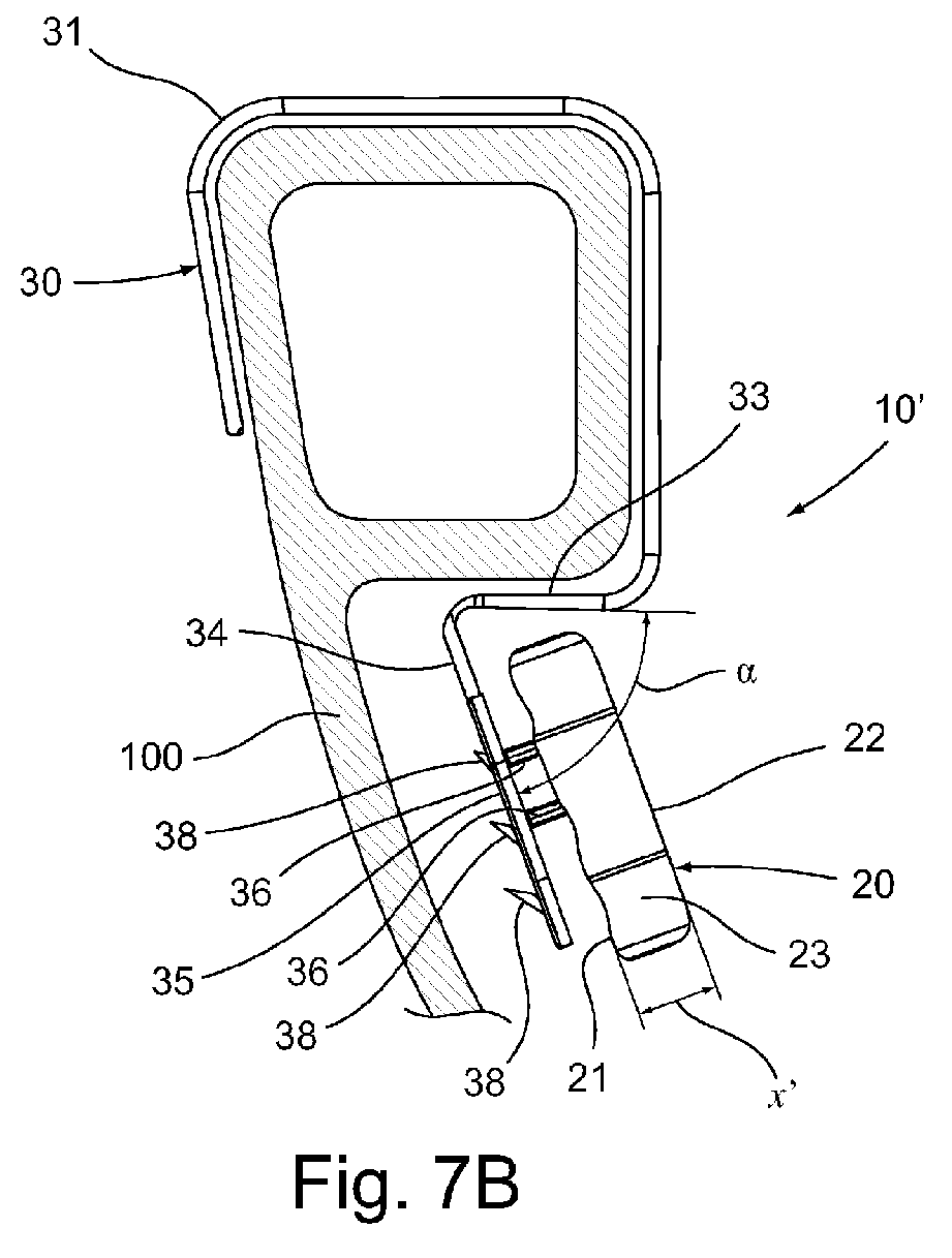
- these show a hygiene device with improved consumption for sanitary appliances, indicated as a whole with 10 and 10', comprising a detergent and/or deodorant means in the form of a solid block 20 and engagement means 30 to a perimetric rim of a WC 100.
- the solid block 20 can be produced in a single piece, or in more pieces by co-extrusion.
- the solid block 20 must have at least one flat rear surface 21 for engagement with the engagement means 30. According to a preferred embodiment, it also has a second flat surface 22, parallel to the first flat rear surface 21.
- the thickness X of the solid block 20 is defined by the distance between the flat surfaces 21 and 22.
- the solid block 20 can also have an outer surface or curved surface 23 perpendicular to the flat surfaces 21, 22, i.e. it can have a tubular form.
- the outer shape i.e. the development of the curved surface, can be of any type but is preferably rounded. In the non-limiting examples shown in the figures, it is in the form of a flower with six rounded petals.
- the engagement means 30 comprise an engagement portion to the WC and an engagement portion with the solid block 20.
- the engagement portion to the WC comprises a flexible hook 31 with three sections, substantially orthogonal to each other, suitable for engagement with the outer, upper and inner edge of the WC 100.
- This element can have variable forms and dimensions.
- the flexible hook can have a variable length, for example by means of a rack-like mechanism. This allows a better positioning of the device with respect to the water flushing in relation to the geometry of the WC and in particular the dimensions of its perimetric rim.
- the engagement portion with the solid block comprises a first supporting arm 33, for spacing the solid block 20 from the side wall of the WC 100, which substantially extends orthogonally with respect to the engagement portion to the WC, so as to be oriented towards the inner wall of the WC 100. It also comprises a second supporting arm 34, for spacing the solid block 20 from the perimetric rim of the WC 100, wherein the supporting arms 33 and 34 are at an angle ⁇ with respect to each other ranging from 1° to 45°.
- a preferred non-limiting embodiment which has provided good results envisages, for example, an angle ⁇ equal to about 20°.
- Both supporting arms 33 and 34 can have a length, for example, ranging from 5 mm to 50 mm to obtain an optimum conveyance of discharge water towards the solid block 20.
- a flat perforated plate 35 carrying at least three pegs 36 perpendicular to it and facing the opposite side with respect to the wall of the WC for the pressure positioning of the solid block 20, extends from the free end of the second supporting arm 34 and is aligned with it.
- the solid block 20 is in fact sufficiently malleable as to be able to be pierced by the pegs 36 and remain anchored to them.
- the pegs 36 have a length ranging from 33% to 99% of the thickness X of the solid block 20 when new and preferably substantially equal to 90%. It has been observed that 90% represents the optimum compromise between the requirement of selecting a minimum length for the pegs which should not be visible during use and the requirement of maintaining the solid block pierced also during the consumption of the same.
- the pegs 36 are preferably positioned in the upper part of the flat plate 35 not aligned with each other, i.e. in an angulated position, a triangle in the example. As shown in the figures for illustrative purposes, a first peg 36 is positioned in the centre of the surface of the flat plate 35, a second and third peg are situated in the upper half of the flat plate 35, between the first peg and second supporting arm 34, in a symmetrical position with respect to a centre plane passing through the first central peg 36.
- the flat plate 35 has dimensions substantially comparable to the flat rear surface 21 of the solid block 20. Substantially comparable dimensions means that the flat perforated plate 35 has a dimension smaller than or at the most equal to the flat rear surface 21 of the solid block 20.
- the perimeter of the flat plate preferably has the same form as the flat rear surface 21 of the solid block 20.
- the hygiene device 10' on the side of the flat plate 35 opposite to the pegs 36, i.e. the rear side which, when the device is in use, is facing the wall of the WC, there is at least one baffle 38 comprising a protruding surface tilted with respect to the flat plate 35, so as to define an angle ⁇ of less than 90° and preferably about 60°.
- the rear side of the flat plate 35 is provided with at least two or, as shown in the figures, preferably three baffles 38.
- the baffles have progressively increasing dimensions from above downwards.
- the maximum protrusion of the baffle increases, i.e. the distance y of the free edge of the baffle measured perpendicularly with respect to the flat plate 35, but also the width z measured in a plane parallel to the flat plate 35.
- the flat perforated plate 35 contains a plurality of openings having variable forms, dimensions and positions.
- the holes 37 of the plate 35 can in fact have various forms and dimensions, for example also like slits (not shown).
- the perforated surface should range from 66% to 2% of the total surface of the flat plate 35 and preferably from 20% to 5%.
- the holes 37 are all situated in the portion of the flat plate 35 between the lower baffle 38, i.e. that furthest away from the supporting arm 34 and the supporting arm 34 itself. According to the invention, it is also sufficient for the greatest density of holes 37 to be upstream the lower baffle 38 in the direction of the flow of discharge water, i.e. in the portion between the supporting arm 34 and lower baffle 38.
- This arrangement of the flat perforated plate 35 with respect to the water flow causes a substantially uniform erosion of the flat surface 21 and progressively a reduction in the thickness of the solid block 20, which, in figures 2B and 7B , is schematized with a reduced thickness X'.
- the base of the pegs 36 becomes progressively visible, but the solid block 20 remains pierced by their tip for its useful life, indicatively ranging from 300 to 500 flushings depending on the dimensions, weight and type of formula.
- a flat perforated plate 35 substantially having the same dimensions as the solid block, or slightly smaller dimensions, has surprisingly allowed the best compromise between duration of the solid block 20 and foaminess to be obtained, preserving, moreover, an aesthetically pleasant surface appearance, regardless of the presence of a turbulent or shower flow in the WC.
- baffles 38 Another important aspect for the quality of the consumption of the solid block 20 also when used in WC with a laminar flow and therefore slightly turbulent, is provided by the presence of baffles 38 in the improved hygiene device 10'.
- the baffles in fact distribute a greater quantity of water through the holes of the flat plate 35 even if the flow washed against the device 10' is slightly turbulent.
- each baffle 38 mainly distributes water through the overlying holes.
- Each baffle 38 also creates a hindrance for the passage of water along the flat perforated plate 35. Consequently, the arrangement of more baffles having a protrusion and width which increase downwardly, with respect to the flow direction of the water, allows a better compromise between the function of distributing the water and hindrance for the passage of water towards the holes downstream.
- the upper baffles convey a part of the water towards the overlying holes but at the same time allow a sufficient passage of water downstream.
- the lower baffles are increasingly wider and more protruding to collect the water not hindered by the upper baffles and send it through the overlying holes.
- the lower portion of the solid block 20 is that whose consumption is less influenced by the presence of holes 37 in the flat plate 35.
- a plurality of holes 37 have been introduced into the flat plate 35, which have dimensions comparable with the solid block 20. These holes unexpectedly allow the passage of water also in the case of extremely difficult and commonly used WC with reduced turbulence and at the same time allow a more regular and gradual consumption.
- the consumption of the solid block 20 occurs starting from the flat rear surface 21.
- This expedient allows the original form of the block to be preserved as much as possible on the front side of the solid block 20 or at least to reduce aesthetic defects due to the not completely uniform erosion.
- the hygiene device with improved consumption for sanitary appliances, object of the present invention, produced in the flat plate, has the advantage of combining good duration and foaminess performances regardless of the type of flushing present in the WC.
- the consumption advantageously occurs gradually starting from the rear side and, in the front, the form of the solid block is preserved for as long as possible in the useful life of the product.
- baffle 38 allows a good production of foam to be maintained even after a certain period of use when consumption has already started, i.e. when the solid block has reduced its thickness x and is no longer immediately close to the flat perforated plate 35.
- the hygiene device with improved consumption for sanitary appliances thus conceived can undergo numerous modifications and variants, all included in the invention; furthermore, all the details can be substituted by technically equivalent elements.
- the materials used, as also the dimensions, can vary according to technical requirements.
Landscapes
- Health & Medical Sciences (AREA)
- Public Health (AREA)
- Epidemiology (AREA)
- Life Sciences & Earth Sciences (AREA)
- Engineering & Computer Science (AREA)
- Hydrology & Water Resources (AREA)
- Water Supply & Treatment (AREA)
- Bidet-Like Cleaning Device And Other Flush Toilet Accessories (AREA)
- Sanitary Device For Flush Toilet (AREA)
- Toilet Supplies (AREA)
Abstract
Description
- The present invention relates to a hygiene device with improved consumption for sanitary appliances.
- The use is known of hygiene devices for sanitary appliances, such as for example WC, to be attached inside the sanitary appliance by means of an appropriate hook that is engaged in the perimetric edge of the same.
- Known hygiene devices can be divided into so-called "solid bars", comprising a detergent and/or deodorant means in the solid state, and so-called "liquid blocks", comprising a detergent and/or deodorant means for WC in the liquid state supplied through a bottle.
- In particular, the first type of hygiene device for WC generally comprises a perforated distributor element, called "cage", equipped with a hook for engagement with the edge of the WC, and containing in its interior the detergent and/or deodorant means in the form of a solid block, also called "soap bar".
- The detergent and/or deodorant means in the solid state is generally currently produced by means of an extrusion process.
- With each flushing of discharge water, the water which flows directly over the distribution cage dissolves and washes away a small quantity of detergent and/or deodorant product from the solid block contained inside the cage.
- One of the drawbacks of these cage devices consists in the high environmental impact of the same. At the end of its use, in fact, when the detergent and/or perfuming means has been used up, the whole distributor element, comprising the hook and cage, is thrown away.
- Furthermore, cage devices, when applied inside WC, are cumbersome and are not aesthetically attractive.
- Other hygiene devices for WC have also been developed, in which the detergent and/or perfuming solid is hung from the perimetric edge through a structure less cumbersome than a cage. Patent application
WO 2007/107750 A1 for example discloses a solid detergent means in which the end of the hook is directly immersed for hanging to the perimetric rim of the WC. The solid detergent means substantially has its entire outer surface exposed to the discharge water. - The main drawback of this device consists in the extremely irregular consumption of the detergent and/or perfuming means, which is aesthetically unattractive already after a relatively low number of flushings of discharge water, equal, for example, to 200 flushings.
- Another example of a hygiene device for WC comprising a detergent and/or perfuming solid means is supplied by patent application
EP 2270286 A1 , which discloses providing the solid block with a central pass-through hole in which a cross-bar is inserted having the suspension hook to the perimetric rim of the WC at one end. - Also in this type of devices, the dimension of the structure is smaller than cage devices, but not to the advantage of the aesthetical appearance of the solid block which contains the pass-through hole. In this case, in fact, the supporting structure is always visible and the defects of the traditional cage are at least partially maintained.
- Furthermore, with the devices described above, the consumption of the solid block is greatly influenced by the type of sanitary appliance in which they are installed, and in particular the type of water flushing.
- An objective of the present invention is to provide a hygiene device with improved consumption for sanitary appliances which solves the drawbacks of the known art indicated above.
- A further objective of the present invention is to provide a hygiene device with improved consumption for sanitary appliances which gives good duration results with a sufficient foaminess level, possibly not particularly influenced by the type of WC, which can have a turbulent or shower flow adhering to the surface.
- Another objective of the present invention is to provide a hygiene device with improved consumption for sanitary appliances which is particularly simple and functional, with reduced costs.
- These objectives according to the present invention are achieved by providing a hygiene device with improved consumption for sanitary appliances as specified in claim 1.
- Further characteristics are indicated in the dependent claims.
- The characteristics and advantages of a hygiene device with improved consumption for sanitary appliances according to the present invention will appear more evident from the following illustrative and non-limiting description, referring to the enclosed schematic drawings, in which:
-
figure 1 is a perspective view of an improved hygiene device with improved consumption for sanitary appliances according to the present invention; -
figure 2A shows a first embodiment of the device offigure 1 applied to a perimetric rim of a WC under conditions of use when new; -
figure 2B schematically shows the device offigure 2A applied to a perimetric rim of a WC under conditions of use after about 200 water flushings; -
figure 3 is a side elevation view of the engagement means of the hygiene device with improved consumption for sanitary appliances offigure 2 according to the invention; -
figure 4 is a perspective view of the engagement means with perforations according to a first illustrative and non-limiting embodiment of the invention; -
figure 5 is an elevation view of the engagement means offigure 4 ; -
figure 6 is an elevation view of the engagement means with perforations according to a further embodiment of the invention; -
figure 7A shows a second improved embodiment of the device offigure 1 applied to a perimetric rim of a WC under conditions of use when new; -
figure 7B schematically shows the device offigure 7A applied to a perimetric rim of a WC under conditions of use after about 200 water flushings; -
figure 8 is an elevation view of the rear side of the engagement means of the improved hygiene device according to the invention, further equipped with a hook having a variable length; -
figure 9 shows an enlarged detail of the baffles of the perfected hygiene device with improved consumption for sanitary appliances according to the present invention. - With reference to the figures, these show a hygiene device with improved consumption for sanitary appliances, indicated as a whole with 10 and 10', comprising a detergent and/or deodorant means in the form of a
solid block 20 and engagement means 30 to a perimetric rim of aWC 100. - The
solid block 20 can be produced in a single piece, or in more pieces by co-extrusion. - The
solid block 20 must have at least one flatrear surface 21 for engagement with the engagement means 30. According to a preferred embodiment, it also has a secondflat surface 22, parallel to the first flatrear surface 21. The thickness X of thesolid block 20 is defined by the distance between theflat surfaces - The
solid block 20 can also have an outer surface orcurved surface 23 perpendicular to theflat surfaces - The engagement means 30 comprise an engagement portion to the WC and an engagement portion with the
solid block 20. - The engagement portion to the WC comprises a
flexible hook 31 with three sections, substantially orthogonal to each other, suitable for engagement with the outer, upper and inner edge of theWC 100. This element can have variable forms and dimensions. According to what is shown for illustrative purposes infigure 8 , the flexible hook can have a variable length, for example by means of a rack-like mechanism. This allows a better positioning of the device with respect to the water flushing in relation to the geometry of the WC and in particular the dimensions of its perimetric rim. - The engagement portion with the solid block comprises a first supporting
arm 33, for spacing thesolid block 20 from the side wall of theWC 100, which substantially extends orthogonally with respect to the engagement portion to the WC, so as to be oriented towards the inner wall of theWC 100. It also comprises a second supportingarm 34, for spacing thesolid block 20 from the perimetric rim of theWC 100, wherein the supportingarms - Both supporting
arms solid block 20. - A flat perforated
plate 35, carrying at least threepegs 36 perpendicular to it and facing the opposite side with respect to the wall of the WC for the pressure positioning of thesolid block 20, extends from the free end of the second supportingarm 34 and is aligned with it. - The
solid block 20 is in fact sufficiently malleable as to be able to be pierced by thepegs 36 and remain anchored to them. - The
pegs 36 have a length ranging from 33% to 99% of the thickness X of thesolid block 20 when new and preferably substantially equal to 90%. It has been observed that 90% represents the optimum compromise between the requirement of selecting a minimum length for the pegs which should not be visible during use and the requirement of maintaining the solid block pierced also during the consumption of the same. - The
pegs 36 are preferably positioned in the upper part of theflat plate 35 not aligned with each other, i.e. in an angulated position, a triangle in the example. As shown in the figures for illustrative purposes, afirst peg 36 is positioned in the centre of the surface of theflat plate 35, a second and third peg are situated in the upper half of theflat plate 35, between the first peg and second supportingarm 34, in a symmetrical position with respect to a centre plane passing through the firstcentral peg 36. - The
flat plate 35 has dimensions substantially comparable to the flatrear surface 21 of thesolid block 20. Substantially comparable dimensions means that the flatperforated plate 35 has a dimension smaller than or at the most equal to the flatrear surface 21 of thesolid block 20. - In particular, it has been observed that an embodiment solution in which the distance of the perimeter of the
flat plate 35 from the perimeter of thesolid block 20 does not exceed 10 mm and preferably does not exceed 5 mm, gives the best results in terms of uniform consumption. - Also when the
flat plate 35 has dimensions smaller than thesolid block 20, the perimeter of the flat plate preferably has the same form as the flatrear surface 21 of thesolid block 20. - According to an improved embodiment of the hygiene device 10' according to the invention, on the side of the
flat plate 35 opposite to thepegs 36, i.e. the rear side which, when the device is in use, is facing the wall of the WC, there is at least onebaffle 38 comprising a protruding surface tilted with respect to theflat plate 35, so as to define an angle β of less than 90° and preferably about 60°. - According to a preferred embodiment, the rear side of the
flat plate 35 is provided with at least two or, as shown in the figures, preferably threebaffles 38. - According to a further preferred embodiment, the baffles have progressively increasing dimensions from above downwards. In particular, starting from the
baffle 38 closest to the supportingarm 34, not only the maximum protrusion of the baffle increases, i.e. the distance y of the free edge of the baffle measured perpendicularly with respect to theflat plate 35, but also the width z measured in a plane parallel to theflat plate 35. - The flat
perforated plate 35 contains a plurality of openings having variable forms, dimensions and positions. Theholes 37 of theplate 35, of which some examples are shown for illustrative purposes in the figures, can in fact have various forms and dimensions, for example also like slits (not shown). - According to the invention, the perforated surface should range from 66% to 2% of the total surface of the
flat plate 35 and preferably from 20% to 5%. - According to the preferred example shown for illustrative purposes in
figure 8 , theholes 37 are all situated in the portion of theflat plate 35 between thelower baffle 38, i.e. that furthest away from the supportingarm 34 and the supportingarm 34 itself. According to the invention, it is also sufficient for the greatest density ofholes 37 to be upstream thelower baffle 38 in the direction of the flow of discharge water, i.e. in the portion between the supportingarm 34 andlower baffle 38. - When functioning, on the perimetric edge of a WC, with each flow of discharge water, the water immerses the hygiene device with improved consumption for
sanitary appliances 10 and 10' differently depending on the type of WC. At the two opposite functioning extremes, there is a turbulent movement or a shower descent adhering to the surface of the WC. In both extremes, the flow of water strikes the flatperforated plate 35 and, through theholes 37, strikes theflat surface 21 of thesolid block 20 washing away a certain quantity of detergent and/or perfuming substance. This arrangement of the flatperforated plate 35 with respect to the water flow causes a substantially uniform erosion of theflat surface 21 and progressively a reduction in the thickness of thesolid block 20, which, infigures 2B and7B , is schematized with a reduced thickness X'. - The base of the
pegs 36 becomes progressively visible, but thesolid block 20 remains pierced by their tip for its useful life, indicatively ranging from 300 to 500 flushings depending on the dimensions, weight and type of formula. - The embodiment of a flat
perforated plate 35 substantially having the same dimensions as the solid block, or slightly smaller dimensions, has surprisingly allowed the best compromise between duration of thesolid block 20 and foaminess to be obtained, preserving, moreover, an aesthetically pleasant surface appearance, regardless of the presence of a turbulent or shower flow in the WC. - Another important aspect for the quality of the consumption of the
solid block 20 also when used in WC with a laminar flow and therefore slightly turbulent, is provided by the presence ofbaffles 38 in the improved hygiene device 10'. The baffles in fact distribute a greater quantity of water through the holes of theflat plate 35 even if the flow washed against the device 10' is slightly turbulent. - In particular, it has been seen that each baffle 38 mainly distributes water through the overlying holes. Each
baffle 38 also creates a hindrance for the passage of water along the flatperforated plate 35. Consequently, the arrangement of more baffles having a protrusion and width which increase downwardly, with respect to the flow direction of the water, allows a better compromise between the function of distributing the water and hindrance for the passage of water towards the holes downstream. In particular, the upper baffles convey a part of the water towards the overlying holes but at the same time allow a sufficient passage of water downstream. The lower baffles are increasingly wider and more protruding to collect the water not hindered by the upper baffles and send it through the overlying holes. Furthermore, it has been observed that the lower portion of thesolid block 20 is that whose consumption is less influenced by the presence ofholes 37 in theflat plate 35. - It has been observed that a flat plate without holes gives good results with respect to duration but in certain types of WC, in which the water descends vertically adhering considerably to the surface, it gives extremely disappointing results with respect to foam. The water in fact is only able to rinse the solid block initially, but after some time the part of the block lying in the back is consumed and the contact between the water and surfactants is extremely limited. This causes the formation of an insufficient quantity of foam.
- It has also been seen that using for the perforated plate a flat surface having a very restricted area with respect to the solid block, produces a large amount of foam, also in WC with a water flow adhering to the surface, but it is rapidly and very irregularly used up, above all in the lower portion.
- In the hygiene device with improved consumption for
sanitary appliances 10 and 10' according to the invention, a plurality ofholes 37 have been introduced into theflat plate 35, which have dimensions comparable with thesolid block 20. These holes unexpectedly allow the passage of water also in the case of extremely difficult and commonly used WC with reduced turbulence and at the same time allow a more regular and gradual consumption. - It has been seen that by allowing the
solid block 20 to have access to the discharge water through theholes 37 rather than reducing the area of theflat plate 35 with respect to the flatrear surface 21 of thesolid block 20, the best results are obtained in terms of uniform consumption of thesolid block 20. - Furthermore, in the hygiene device with improved consumption for
sanitary appliances 10 and 10', according to the invention, the consumption of thesolid block 20 occurs starting from the flatrear surface 21. This expedient allows the original form of the block to be preserved as much as possible on the front side of thesolid block 20 or at least to reduce aesthetic defects due to the not completely uniform erosion. - The hygiene device with improved consumption for sanitary appliances, object of the present invention, produced in the flat plate, has the advantage of combining good duration and foaminess performances regardless of the type of flushing present in the WC.
- The consumption advantageously occurs gradually starting from the rear side and, in the front, the form of the solid block is preserved for as long as possible in the useful life of the product.
- It has also been observed that the presence of at least one
baffle 38 allows a good production of foam to be maintained even after a certain period of use when consumption has already started, i.e. when the solid block has reduced its thickness x and is no longer immediately close to the flatperforated plate 35. - The hygiene device with improved consumption for sanitary appliances thus conceived can undergo numerous modifications and variants, all included in the invention; furthermore, all the details can be substituted by technically equivalent elements. In practice, the materials used, as also the dimensions, can vary according to technical requirements.
Claims (15)
- A hygiene device with improved consumption for sanitary appliances (10,10') comprising a detergent and/or deodorant means in the form of a solid block (20) and engagement means (30) to a perimetric rim of a WC (100), wherein said engagement means (30) comprise an engagement portion to the WC (31) and an engagement portion (33, 34, 35) to said solid block (20), and wherein said solid block (20) comprises at least one flat rear surface (21) for engagement with said engagement means (30), characterized in that said engagement portion with the solid block (20) comprises a flat perforated plate (35), having at least three pegs (36) perpendicular to it and facing the opposite side with respect to the wall of the WC for the pressure positioning of the solid block (20), wherein said flat perforated plate (35) has a dimension smaller than or at the most equal to the flat rear surface (21) of the solid block (20).
- The device according to claim 1, characterized in that said flat perforated plate (35) carries, on the opposite side with respect to said pegs (36), at least one baffle (38) comprising a protruding surface, tilted with respect to the flat plate (35) by an angle β of less than 90°.
- The device according to claim 2, characterized in that said flat perforated plate (35) comprises at least two baffles (38).
- The device according to claim 3, characterized in that the maximum protrusion and/or width of said at least two baffles (38) progressively increases from the top to the bottom of said flat plate (35) in the flow direction of the flushing water.
- The device according to any of the previous claims from 2 to 4, characterized in that said flat perforated plate (35) has the greatest density of holes upstream of the lower baffle (38) in the flow direction of the flushing water.
- The device according to claim 5, characterized in that all of the holes (37) are situated upstream of the lower baffle (38).
- The device according to any of the previous claims, characterized in that said flat perforated plate (35) has a perforated surface ranging from 66% to 2% of the overall surface of the flat plate (35).
- The device according to claim 7, characterized in that said flat perforated plate (35) has a perforated surface ranging from 20% to 5% of the overall surface of the flat plate (35).
- The device according to any of the previous claims, characterized in that said pegs (36) are positioned in the upper part of the flat perforated plate (35) in an angled position with respect to each other.
- The device according to claim 9, characterized in that a first of said pegs (36) is situated in the centre of the surface of said flat plate (35) and a second and third of said pegs (36) are situated in the upper half of the flat plate (35), in a symmetrical position with respect to a central plane passing through said first central peg (36).
- The device according to any of the previous claims, characterized in that said solid block (20) comprises a second flat surface (22), parallel to the first flat rear surface (21), a thickness (X) of the solid block (20) being defined by the distance between said flat surfaces (21, 22).
- The device according to claim 9, characterized in that said pegs (36) have a length ranging from 33% to 99% of the thickness (X) of the solid block (20) when new and preferably substantially equal to 90%.
- The device according to any of the previous claims, characterized in that the distance of the perimeter of said flat perforated plate (35) from the perimeter of said solid block (20) does not exceed 10 mm, and preferably does not exceed 5 mm.
- The device according to any of the previous claims, characterized in that said flat perforated plate (35) has a perimeter having the same form as the flat rear surface (21) of the solid block (20).
- The device according to any of the previous claims, characterized in that said engagement portion with the solid block comprises a first supporting arm (33), for spacing said solid block (20) from the side wall of the WC (100), said first supporting arm (33) extending from the engagement portion with the WC so as to be oriented towards the internal wall of the WC, and a second supporting arm (34) for spacing the solid block (20) from the perimetric rim of the WC (100), wherein said supporting arms (33, 34) are mutually angled with an angle (α) of approximately 45°.
Priority Applications (5)
| Application Number | Priority Date | Filing Date | Title |
|---|---|---|---|
| SM20180349T SMT201800349T1 (en) | 2011-07-01 | 2012-06-29 | Hygiene device with improved consumption for sanitary appliances |
| RS20180520A RS57212B1 (en) | 2011-07-01 | 2012-06-29 | Hygiene device with improved consumption for sanitary appliances |
| PL12174344T PL2540918T3 (en) | 2011-07-01 | 2012-06-29 | Hygiene device with improved consumption for sanitary appliances |
| SI201231294T SI2540918T1 (en) | 2011-07-01 | 2012-06-29 | Hygienic device with improved consumption for sanitary appliances |
| HRP20180766TT HRP20180766T1 (en) | 2011-07-01 | 2018-05-16 | HYGIENE DEVICE WITH IMPROVED CONSUMPTION FOR SANITARY APPLIANCES |
Applications Claiming Priority (2)
| Application Number | Priority Date | Filing Date | Title |
|---|---|---|---|
| IT001232A ITMI20111232A1 (en) | 2011-07-01 | 2011-07-01 | HYGIENIC DEVICE WITH IMPROVED CONSUMPTION FOR SANITARY APPLIANCES |
| IT001720A ITMI20111720A1 (en) | 2011-09-23 | 2011-09-23 | HYGIENIC DEVICE PERFECTED WITH IMPROVED CONSUMPTION FOR SANITARY APPLIANCES |
Publications (2)
| Publication Number | Publication Date |
|---|---|
| EP2540918A1 true EP2540918A1 (en) | 2013-01-02 |
| EP2540918B1 EP2540918B1 (en) | 2018-02-21 |
Family
ID=46320838
Family Applications (1)
| Application Number | Title | Priority Date | Filing Date |
|---|---|---|---|
| EP12174344.7A Active EP2540918B1 (en) | 2011-07-01 | 2012-06-29 | Hygiene device with improved consumption for sanitary appliances |
Country Status (10)
| Country | Link |
|---|---|
| EP (1) | EP2540918B1 (en) |
| CY (1) | CY1120563T1 (en) |
| ES (1) | ES2668918T3 (en) |
| HR (1) | HRP20180766T1 (en) |
| LT (1) | LT2540918T (en) |
| PL (1) | PL2540918T3 (en) |
| PT (1) | PT2540918T (en) |
| RS (1) | RS57212B1 (en) |
| SI (1) | SI2540918T1 (en) |
| SM (1) | SMT201800349T1 (en) |
Cited By (2)
| Publication number | Priority date | Publication date | Assignee | Title |
|---|---|---|---|---|
| CN110820881A (en) * | 2019-04-25 | 2020-02-21 | 广州蓝月亮实业有限公司 | A delayed release device for toilet cleaning supplies |
| EP4450722A1 (en) | 2023-04-19 | 2024-10-23 | Wayne Desmond Burgis | Toilet hygiene apparatus |
Citations (8)
| Publication number | Priority date | Publication date | Assignee | Title |
|---|---|---|---|---|
| AT293965B (en) * | 1968-07-19 | 1971-11-10 | Gade Chem Fab Kurt | Device for using means for cleaning, disinfecting and improving the odor in water closet basins or the like. |
| US3766576A (en) * | 1971-07-14 | 1973-10-23 | Chemtrust Ind Corp | Lavatory sanitation bodies |
| US4096593A (en) * | 1976-07-15 | 1978-06-27 | Eftichios Van Vlahakis | Toilet bowl dispenser |
| GB2416785A (en) * | 2004-08-04 | 2006-02-08 | Reckitt Benckiser Inc | Device for dispensing a treatment composition and a fragrancing effect to an item of sanitaryware. |
| WO2007107750A1 (en) | 2006-03-22 | 2007-09-27 | Reckitt Benckiser Inc | Improvements in dispensing devices |
| WO2009034304A1 (en) * | 2007-09-14 | 2009-03-19 | Reckitt Benckiser Inc. | Improvements in lavatory treatment devices |
| EP2270286A1 (en) | 2009-06-30 | 2011-01-05 | RE.LE.VI. S.p.a. | Dispenser of active substances for WC bowls |
| US20110138526A1 (en) * | 2009-12-10 | 2011-06-16 | Jin-Yang Hsu | Toilet chemical dispenser |
-
2012
- 2012-06-29 EP EP12174344.7A patent/EP2540918B1/en active Active
- 2012-06-29 SI SI201231294T patent/SI2540918T1/en unknown
- 2012-06-29 ES ES12174344.7T patent/ES2668918T3/en active Active
- 2012-06-29 PT PT121743447T patent/PT2540918T/en unknown
- 2012-06-29 LT LTEP12174344.7T patent/LT2540918T/en unknown
- 2012-06-29 PL PL12174344T patent/PL2540918T3/en unknown
- 2012-06-29 RS RS20180520A patent/RS57212B1/en unknown
- 2012-06-29 SM SM20180349T patent/SMT201800349T1/en unknown
-
2018
- 2018-05-15 CY CY20181100496T patent/CY1120563T1/en unknown
- 2018-05-16 HR HRP20180766TT patent/HRP20180766T1/en unknown
Patent Citations (8)
| Publication number | Priority date | Publication date | Assignee | Title |
|---|---|---|---|---|
| AT293965B (en) * | 1968-07-19 | 1971-11-10 | Gade Chem Fab Kurt | Device for using means for cleaning, disinfecting and improving the odor in water closet basins or the like. |
| US3766576A (en) * | 1971-07-14 | 1973-10-23 | Chemtrust Ind Corp | Lavatory sanitation bodies |
| US4096593A (en) * | 1976-07-15 | 1978-06-27 | Eftichios Van Vlahakis | Toilet bowl dispenser |
| GB2416785A (en) * | 2004-08-04 | 2006-02-08 | Reckitt Benckiser Inc | Device for dispensing a treatment composition and a fragrancing effect to an item of sanitaryware. |
| WO2007107750A1 (en) | 2006-03-22 | 2007-09-27 | Reckitt Benckiser Inc | Improvements in dispensing devices |
| WO2009034304A1 (en) * | 2007-09-14 | 2009-03-19 | Reckitt Benckiser Inc. | Improvements in lavatory treatment devices |
| EP2270286A1 (en) | 2009-06-30 | 2011-01-05 | RE.LE.VI. S.p.a. | Dispenser of active substances for WC bowls |
| US20110138526A1 (en) * | 2009-12-10 | 2011-06-16 | Jin-Yang Hsu | Toilet chemical dispenser |
Cited By (3)
| Publication number | Priority date | Publication date | Assignee | Title |
|---|---|---|---|---|
| CN110820881A (en) * | 2019-04-25 | 2020-02-21 | 广州蓝月亮实业有限公司 | A delayed release device for toilet cleaning supplies |
| CN110820881B (en) * | 2019-04-25 | 2022-01-18 | 广州蓝月亮实业有限公司 | Delay release device for toilet cleaning articles |
| EP4450722A1 (en) | 2023-04-19 | 2024-10-23 | Wayne Desmond Burgis | Toilet hygiene apparatus |
Also Published As
| Publication number | Publication date |
|---|---|
| PT2540918T (en) | 2018-05-21 |
| ES2668918T3 (en) | 2018-05-23 |
| LT2540918T (en) | 2018-06-11 |
| RS57212B1 (en) | 2018-07-31 |
| EP2540918B1 (en) | 2018-02-21 |
| PL2540918T3 (en) | 2018-08-31 |
| CY1120563T1 (en) | 2019-07-10 |
| SI2540918T1 (en) | 2018-07-31 |
| HRP20180766T1 (en) | 2018-06-29 |
| SMT201800349T1 (en) | 2018-09-13 |
Similar Documents
| Publication | Publication Date | Title |
|---|---|---|
| US10669704B2 (en) | Toilet balls with flushing water distributor | |
| JP4705631B2 (en) | Dispenser that releases treatment agent into the toilet | |
| EP1674625A1 (en) | Device for dispensing active components packaged in a tablet or bar in toilet bowls or water-using sanitary fixtures in general | |
| JP7009478B2 (en) | Toilet shatterproof device | |
| EP2540918B1 (en) | Hygiene device with improved consumption for sanitary appliances | |
| JP2015165084A (en) | Holder and chemical supplier with holder | |
| CN110820881B (en) | Delay release device for toilet cleaning articles | |
| JP5445980B2 (en) | Drug case | |
| KR200486306Y1 (en) | Fixing structure of soap holder | |
| JP4457719B2 (en) | Chemical discharge container | |
| JP2009112756A (en) | Soap storage case with aqueous solution receiver | |
| ITMI20111720A1 (en) | HYGIENIC DEVICE PERFECTED WITH IMPROVED CONSUMPTION FOR SANITARY APPLIANCES | |
| JP4341339B2 (en) | Chemical discharge container | |
| ITMI20111232A1 (en) | HYGIENIC DEVICE WITH IMPROVED CONSUMPTION FOR SANITARY APPLIANCES | |
| JP2011055866A (en) | Wash basin stand | |
| CN118309146A (en) | A hanging release box for toilet cleaning ball and a hanging toilet cleaning device | |
| RS64816B1 (en) | Device for sanitary fittings bowls with vortical flow inside the device and related tablet of chemical product | |
| JP2010070966A (en) | Chemical liquid feeder for urinal | |
| CN201211134Y (en) | Cleaning avoidance fruit pad | |
| JP2001115533A (en) | Urinal | |
| JP4475123B2 (en) | Bathroom with water intrusion prevention function | |
| CN109208729A (en) | The water curtain flushing structure of deodorization trough urinal and trough urinal with the structure | |
| PL16598S2 (en) | K o m p l e t l a z i e n k o w y | |
| KR20140005029U (en) | Washstand with a Soap Holder | |
| TWM327883U (en) | Double-trough-type triple-effect pipetting device with cleaning mechanism |
Legal Events
| Date | Code | Title | Description |
|---|---|---|---|
| PUAI | Public reference made under article 153(3) epc to a published international application that has entered the european phase |
Free format text: ORIGINAL CODE: 0009012 |
|
| AK | Designated contracting states |
Kind code of ref document: A1 Designated state(s): AL AT BE BG CH CY CZ DE DK EE ES FI FR GB GR HR HU IE IS IT LI LT LU LV MC MK MT NL NO PL PT RO RS SE SI SK SM TR |
|
| AX | Request for extension of the european patent |
Extension state: BA ME |
|
| 17P | Request for examination filed |
Effective date: 20130626 |
|
| RBV | Designated contracting states (corrected) |
Designated state(s): AL AT BE BG CH CY CZ DE DK EE ES FI FR GB GR HR HU IE IS IT LI LT LU LV MC MK MT NL NO PL PT RO RS SE SI SK SM TR |
|
| STAA | Information on the status of an ep patent application or granted ep patent |
Free format text: STATUS: EXAMINATION IS IN PROGRESS |
|
| 17Q | First examination report despatched |
Effective date: 20170310 |
|
| GRAP | Despatch of communication of intention to grant a patent |
Free format text: ORIGINAL CODE: EPIDOSNIGR1 |
|
| STAA | Information on the status of an ep patent application or granted ep patent |
Free format text: STATUS: GRANT OF PATENT IS INTENDED |
|
| INTG | Intention to grant announced |
Effective date: 20170912 |
|
| GRAS | Grant fee paid |
Free format text: ORIGINAL CODE: EPIDOSNIGR3 |
|
| GRAA | (expected) grant |
Free format text: ORIGINAL CODE: 0009210 |
|
| STAA | Information on the status of an ep patent application or granted ep patent |
Free format text: STATUS: THE PATENT HAS BEEN GRANTED |
|
| AK | Designated contracting states |
Kind code of ref document: B1 Designated state(s): AL AT BE BG CH CY CZ DE DK EE ES FI FR GB GR HR HU IE IS IT LI LT LU LV MC MK MT NL NO PL PT RO RS SE SI SK SM TR |
|
| REG | Reference to a national code |
Ref country code: GB Ref legal event code: FG4D |
|
| REG | Reference to a national code |
Ref country code: CH Ref legal event code: EP |
|
| REG | Reference to a national code |
Ref country code: AT Ref legal event code: REF Ref document number: 971871 Country of ref document: AT Kind code of ref document: T Effective date: 20180315 |
|
| REG | Reference to a national code |
Ref country code: IE Ref legal event code: FG4D |
|
| REG | Reference to a national code |
Ref country code: DE Ref legal event code: R096 Ref document number: 602012042954 Country of ref document: DE |
|
| REG | Reference to a national code |
Ref country code: HR Ref legal event code: TUEP Ref document number: P20180766 Country of ref document: HR |
|
| REG | Reference to a national code |
Ref country code: PT Ref legal event code: SC4A Ref document number: 2540918 Country of ref document: PT Date of ref document: 20180521 Kind code of ref document: T Free format text: AVAILABILITY OF NATIONAL TRANSLATION Effective date: 20180514 |
|
| REG | Reference to a national code |
Ref country code: HR Ref legal event code: ODRP Ref document number: P20180766 Country of ref document: HR Payment date: 20180523 Year of fee payment: 7 Ref country code: ES Ref legal event code: FG2A Ref document number: 2668918 Country of ref document: ES Kind code of ref document: T3 Effective date: 20180523 |
|
| REG | Reference to a national code |
Ref country code: NL Ref legal event code: FP |
|
| REG | Reference to a national code |
Ref country code: FR Ref legal event code: PLFP Year of fee payment: 7 |
|
| REG | Reference to a national code |
Ref country code: HR Ref legal event code: T1PR Ref document number: P20180766 Country of ref document: HR |
|
| PG25 | Lapsed in a contracting state [announced via postgrant information from national office to epo] |
Ref country code: NO Free format text: LAPSE BECAUSE OF FAILURE TO SUBMIT A TRANSLATION OF THE DESCRIPTION OR TO PAY THE FEE WITHIN THE PRESCRIBED TIME-LIMIT Effective date: 20180521 Ref country code: FI Free format text: LAPSE BECAUSE OF FAILURE TO SUBMIT A TRANSLATION OF THE DESCRIPTION OR TO PAY THE FEE WITHIN THE PRESCRIBED TIME-LIMIT Effective date: 20180221 |
|
| PGFP | Annual fee paid to national office [announced via postgrant information from national office to epo] |
Ref country code: MC Payment date: 20180626 Year of fee payment: 7 Ref country code: DE Payment date: 20180613 Year of fee payment: 7 Ref country code: CZ Payment date: 20180502 Year of fee payment: 7 Ref country code: CH Payment date: 20180626 Year of fee payment: 7 Ref country code: HR Payment date: 20180523 Year of fee payment: 7 Ref country code: IE Payment date: 20180621 Year of fee payment: 7 Ref country code: LT Payment date: 20180521 Year of fee payment: 7 Ref country code: NL Payment date: 20180627 Year of fee payment: 7 Ref country code: PT Payment date: 20180521 Year of fee payment: 7 |
|
| PG25 | Lapsed in a contracting state [announced via postgrant information from national office to epo] |
Ref country code: SE Free format text: LAPSE BECAUSE OF FAILURE TO SUBMIT A TRANSLATION OF THE DESCRIPTION OR TO PAY THE FEE WITHIN THE PRESCRIBED TIME-LIMIT Effective date: 20180221 Ref country code: BG Free format text: LAPSE BECAUSE OF FAILURE TO SUBMIT A TRANSLATION OF THE DESCRIPTION OR TO PAY THE FEE WITHIN THE PRESCRIBED TIME-LIMIT Effective date: 20180521 |
|
| PGFP | Annual fee paid to national office [announced via postgrant information from national office to epo] |
Ref country code: GB Payment date: 20180626 Year of fee payment: 12 Ref country code: GR Payment date: 20180529 Year of fee payment: 7 Ref country code: PL Payment date: 20180607 Year of fee payment: 7 Ref country code: SI Payment date: 20180503 Year of fee payment: 7 Ref country code: BE Payment date: 20180627 Year of fee payment: 7 Ref country code: FR Payment date: 20180626 Year of fee payment: 7 Ref country code: LV Payment date: 20180518 Year of fee payment: 7 Ref country code: AT Payment date: 20180621 Year of fee payment: 7 Ref country code: LU Payment date: 20180629 Year of fee payment: 7 |
|
| PG25 | Lapsed in a contracting state [announced via postgrant information from national office to epo] |
Ref country code: AL Free format text: LAPSE BECAUSE OF FAILURE TO SUBMIT A TRANSLATION OF THE DESCRIPTION OR TO PAY THE FEE WITHIN THE PRESCRIBED TIME-LIMIT Effective date: 20180221 Ref country code: RO Free format text: LAPSE BECAUSE OF FAILURE TO SUBMIT A TRANSLATION OF THE DESCRIPTION OR TO PAY THE FEE WITHIN THE PRESCRIBED TIME-LIMIT Effective date: 20180221 Ref country code: EE Free format text: LAPSE BECAUSE OF FAILURE TO SUBMIT A TRANSLATION OF THE DESCRIPTION OR TO PAY THE FEE WITHIN THE PRESCRIBED TIME-LIMIT Effective date: 20180221 |
|
| PGFP | Annual fee paid to national office [announced via postgrant information from national office to epo] |
Ref country code: ES Payment date: 20180711 Year of fee payment: 7 |
|
| REG | Reference to a national code |
Ref country code: GR Ref legal event code: EP Ref document number: 20180401324 Country of ref document: GR Effective date: 20181012 |
|
| REG | Reference to a national code |
Ref country code: DE Ref legal event code: R097 Ref document number: 602012042954 Country of ref document: DE |
|
| PG25 | Lapsed in a contracting state [announced via postgrant information from national office to epo] |
Ref country code: DK Free format text: LAPSE BECAUSE OF FAILURE TO SUBMIT A TRANSLATION OF THE DESCRIPTION OR TO PAY THE FEE WITHIN THE PRESCRIBED TIME-LIMIT Effective date: 20180221 |
|
| PGFP | Annual fee paid to national office [announced via postgrant information from national office to epo] |
Ref country code: SK Payment date: 20180502 Year of fee payment: 7 Ref country code: SM Payment date: 20180710 Year of fee payment: 7 |
|
| PLBE | No opposition filed within time limit |
Free format text: ORIGINAL CODE: 0009261 |
|
| STAA | Information on the status of an ep patent application or granted ep patent |
Free format text: STATUS: NO OPPOSITION FILED WITHIN TIME LIMIT |
|
| 26N | No opposition filed |
Effective date: 20181122 |
|
| PGFP | Annual fee paid to national office [announced via postgrant information from national office to epo] |
Ref country code: CY Payment date: 20180620 Year of fee payment: 7 |
|
| PGFP | Annual fee paid to national office [announced via postgrant information from national office to epo] |
Ref country code: MK Payment date: 20180516 Year of fee payment: 7 |
|
| REG | Reference to a national code |
Ref country code: DE Ref legal event code: R119 Ref document number: 602012042954 Country of ref document: DE |
|
| REG | Reference to a national code |
Ref country code: HR Ref legal event code: PBON Ref document number: P20180766 Country of ref document: HR Effective date: 20190629 |
|
| REG | Reference to a national code |
Ref country code: LT Ref legal event code: MM4D Effective date: 20190629 |
|
| PG25 | Lapsed in a contracting state [announced via postgrant information from national office to epo] |
Ref country code: CY Free format text: LAPSE BECAUSE OF NON-PAYMENT OF DUE FEES Effective date: 20190629 Ref country code: PT Free format text: LAPSE BECAUSE OF NON-PAYMENT OF DUE FEES Effective date: 20191230 Ref country code: MC Free format text: LAPSE BECAUSE OF NON-PAYMENT OF DUE FEES Effective date: 20190701 Ref country code: CZ Free format text: LAPSE BECAUSE OF NON-PAYMENT OF DUE FEES Effective date: 20190629 |
|
| REG | Reference to a national code |
Ref country code: CH Ref legal event code: PL |
|
| REG | Reference to a national code |
Ref country code: NL Ref legal event code: MM Effective date: 20190701 |
|
| REG | Reference to a national code |
Ref country code: AT Ref legal event code: MM01 Ref document number: 971871 Country of ref document: AT Kind code of ref document: T Effective date: 20190629 |
|
| GBPC | Gb: european patent ceased through non-payment of renewal fee |
Effective date: 20190629 |
|
| PG25 | Lapsed in a contracting state [announced via postgrant information from national office to epo] |
Ref country code: LV Free format text: LAPSE BECAUSE OF NON-PAYMENT OF DUE FEES Effective date: 20190629 Ref country code: RS Free format text: LAPSE BECAUSE OF NON-PAYMENT OF DUE FEES Effective date: 20191231 |
|
| REG | Reference to a national code |
Ref country code: SK Ref legal event code: MM4A Ref document number: E 27325 Country of ref document: SK Effective date: 20190629 |
|
| REG | Reference to a national code |
Ref country code: BE Ref legal event code: MM Effective date: 20190630 |
|
| PG25 | Lapsed in a contracting state [announced via postgrant information from national office to epo] |
Ref country code: TR Free format text: LAPSE BECAUSE OF FAILURE TO SUBMIT A TRANSLATION OF THE DESCRIPTION OR TO PAY THE FEE WITHIN THE PRESCRIBED TIME-LIMIT Effective date: 20180221 |
|
| PGFP | Annual fee paid to national office [announced via postgrant information from national office to epo] |
Ref country code: MT Payment date: 20180629 Year of fee payment: 7 |
|
| REG | Reference to a national code |
Ref country code: SI Ref legal event code: KO00 Effective date: 20200210 |
|
| REG | Reference to a national code |
Ref country code: AT Ref legal event code: UEP Ref document number: 971871 Country of ref document: AT Kind code of ref document: T Effective date: 20180221 |
|
| PG25 | Lapsed in a contracting state [announced via postgrant information from national office to epo] |
Ref country code: DE Free format text: LAPSE BECAUSE OF NON-PAYMENT OF DUE FEES Effective date: 20200101 Ref country code: GB Free format text: LAPSE BECAUSE OF NON-PAYMENT OF DUE FEES Effective date: 20190629 Ref country code: NL Free format text: LAPSE BECAUSE OF NON-PAYMENT OF DUE FEES Effective date: 20190701 Ref country code: LT Free format text: LAPSE BECAUSE OF NON-PAYMENT OF DUE FEES Effective date: 20190629 Ref country code: GR Free format text: LAPSE BECAUSE OF NON-PAYMENT OF DUE FEES Effective date: 20200107 Ref country code: AT Free format text: LAPSE BECAUSE OF NON-PAYMENT OF DUE FEES Effective date: 20190629 Ref country code: IE Free format text: LAPSE BECAUSE OF NON-PAYMENT OF DUE FEES Effective date: 20190629 |
|
| PG25 | Lapsed in a contracting state [announced via postgrant information from national office to epo] |
Ref country code: BE Free format text: LAPSE BECAUSE OF NON-PAYMENT OF DUE FEES Effective date: 20190630 Ref country code: HU Free format text: LAPSE BECAUSE OF FAILURE TO SUBMIT A TRANSLATION OF THE DESCRIPTION OR TO PAY THE FEE WITHIN THE PRESCRIBED TIME-LIMIT; INVALID AB INITIO Effective date: 20120629 Ref country code: LU Free format text: LAPSE BECAUSE OF NON-PAYMENT OF DUE FEES Effective date: 20190629 Ref country code: HR Free format text: LAPSE BECAUSE OF NON-PAYMENT OF DUE FEES Effective date: 20190629 Ref country code: SM Free format text: LAPSE BECAUSE OF NON-PAYMENT OF DUE FEES Effective date: 20200113 Ref country code: SK Free format text: LAPSE BECAUSE OF NON-PAYMENT OF DUE FEES Effective date: 20190629 Ref country code: LI Free format text: LAPSE BECAUSE OF NON-PAYMENT OF DUE FEES Effective date: 20190630 Ref country code: SI Free format text: LAPSE BECAUSE OF NON-PAYMENT OF DUE FEES Effective date: 20190630 Ref country code: CH Free format text: LAPSE BECAUSE OF NON-PAYMENT OF DUE FEES Effective date: 20190630 |
|
| PG25 | Lapsed in a contracting state [announced via postgrant information from national office to epo] |
Ref country code: FR Free format text: LAPSE BECAUSE OF NON-PAYMENT OF DUE FEES Effective date: 20190630 |
|
| PG25 | Lapsed in a contracting state [announced via postgrant information from national office to epo] |
Ref country code: IS Free format text: LAPSE BECAUSE OF FAILURE TO SUBMIT A TRANSLATION OF THE DESCRIPTION OR TO PAY THE FEE WITHIN THE PRESCRIBED TIME-LIMIT Effective date: 20180621 |
|
| PGFP | Annual fee paid to national office [announced via postgrant information from national office to epo] |
Ref country code: IT Payment date: 20200612 Year of fee payment: 9 |
|
| REG | Reference to a national code |
Ref country code: ES Ref legal event code: FD2A Effective date: 20201030 |
|
| PG25 | Lapsed in a contracting state [announced via postgrant information from national office to epo] |
Ref country code: ES Free format text: LAPSE BECAUSE OF NON-PAYMENT OF DUE FEES Effective date: 20190630 |
|
| PG25 | Lapsed in a contracting state [announced via postgrant information from national office to epo] |
Ref country code: MT Free format text: LAPSE BECAUSE OF FAILURE TO SUBMIT A TRANSLATION OF THE DESCRIPTION OR TO PAY THE FEE WITHIN THE PRESCRIBED TIME-LIMIT Effective date: 20190629 |
|
| PG25 | Lapsed in a contracting state [announced via postgrant information from national office to epo] |
Ref country code: PL Free format text: LAPSE BECAUSE OF NON-PAYMENT OF DUE FEES Effective date: 20190629 |
|
| PG25 | Lapsed in a contracting state [announced via postgrant information from national office to epo] |
Ref country code: IT Free format text: LAPSE BECAUSE OF NON-PAYMENT OF DUE FEES Effective date: 20210629 |