EP2540888A2 - Method and apparatus for knit design - Google Patents
Method and apparatus for knit design Download PDFInfo
- Publication number
- EP2540888A2 EP2540888A2 EP12004364A EP12004364A EP2540888A2 EP 2540888 A2 EP2540888 A2 EP 2540888A2 EP 12004364 A EP12004364 A EP 12004364A EP 12004364 A EP12004364 A EP 12004364A EP 2540888 A2 EP2540888 A2 EP 2540888A2
- Authority
- EP
- European Patent Office
- Prior art keywords
- knitting
- area
- pattern
- specified
- specified area
- Prior art date
- Legal status (The legal status is an assumption and is not a legal conclusion. Google has not performed a legal analysis and makes no representation as to the accuracy of the status listed.)
- Granted
Links
Images




Classifications
-
- D—TEXTILES; PAPER
- D04—BRAIDING; LACE-MAKING; KNITTING; TRIMMINGS; NON-WOVEN FABRICS
- D04B—KNITTING
- D04B7/00—Flat-bed knitting machines with independently-movable needles
- D04B7/24—Flat-bed knitting machines with independently-movable needles for producing patterned fabrics
-
- D—TEXTILES; PAPER
- D04—BRAIDING; LACE-MAKING; KNITTING; TRIMMINGS; NON-WOVEN FABRICS
- D04B—KNITTING
- D04B7/00—Flat-bed knitting machines with independently-movable needles
- D04B7/24—Flat-bed knitting machines with independently-movable needles for producing patterned fabrics
- D04B7/26—Flat-bed knitting machines with independently-movable needles for producing patterned fabrics with colour patterns
-
- D—TEXTILES; PAPER
- D04—BRAIDING; LACE-MAKING; KNITTING; TRIMMINGS; NON-WOVEN FABRICS
- D04B—KNITTING
- D04B1/00—Weft knitting processes for the production of fabrics or articles not dependent on the use of particular machines; Fabrics or articles defined by such processes
- D04B1/10—Patterned fabrics or articles
- D04B1/12—Patterned fabrics or articles characterised by thread material
- D04B1/126—Patterned fabrics or articles characterised by thread material with colour pattern, e.g. intarsia fabrics
-
- D—TEXTILES; PAPER
- D04—BRAIDING; LACE-MAKING; KNITTING; TRIMMINGS; NON-WOVEN FABRICS
- D04B—KNITTING
- D04B15/00—Details of, or auxiliary devices incorporated in, weft knitting machines, restricted to machines of this kind
- D04B15/66—Devices for determining or controlling patterns ; Program-control arrangements
-
- D—TEXTILES; PAPER
- D04—BRAIDING; LACE-MAKING; KNITTING; TRIMMINGS; NON-WOVEN FABRICS
- D04B—KNITTING
- D04B15/00—Details of, or auxiliary devices incorporated in, weft knitting machines, restricted to machines of this kind
- D04B15/66—Devices for determining or controlling patterns ; Program-control arrangements
- D04B15/68—Devices for determining or controlling patterns ; Program-control arrangements characterised by the knitting instruments used
- D04B15/70—Devices for determining or controlling patterns ; Program-control arrangements characterised by the knitting instruments used in flat-bed knitting machines
-
- D—TEXTILES; PAPER
- D04—BRAIDING; LACE-MAKING; KNITTING; TRIMMINGS; NON-WOVEN FABRICS
- D04B—KNITTING
- D04B35/00—Details of, or auxiliary devices incorporated in, knitting machines, not otherwise provided for
-
- D—TEXTILES; PAPER
- D04—BRAIDING; LACE-MAKING; KNITTING; TRIMMINGS; NON-WOVEN FABRICS
- D04B—KNITTING
- D04B37/00—Auxiliary apparatus or devices for use with knitting machines
- D04B37/02—Auxiliary apparatus or devices for use with knitting machines with weft knitting machines
Definitions
- the present invention relates to a knit design method and a knit design apparatus, in order to knit fabrics by a flatbed knitting machine of computer control.
- a flatbed knitting machine which is used to produce knit products is controlled by a computer such that selection of knitting needles, run of a carriage, switch of knitting yarns, or the like are performed in accordance with knitting data which is preliminarily prepared.
- a knit design apparatus is used to prepare the knitting data (for example, see Patent Literature 1).
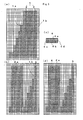
- Figs. 5 show a basic way of thinking about a knit design method and an apparatus for knit design, disclosed in the Patent Literature 1, and an outline of a method for designing a pattern to apply the basic way of thinking.
- Fig. 5(a) shows a knitting stitch image 1 as a base of design for a knitted fabric product.
- the knitting stitch image is generated, while being displayed on a display device of the apparatus for knit design as an image, in accordance with data for each knitting stitch input by a user.
- Cells displayed in a screen represent knitting stitches, types of knitting stitches are expressed with specific colors instead of letter symbols for knitting stitch used in hand knitting or hand knitting machine, and color codes corresponding to the colors are input to knitting stitch data.
- knitting stitches are sequentially formed in a course direction which is transversal, and the courses, which are sequentially formed, are joined to one another in a wale direction which is longitudinal so that a knitted fabric is formed.
- a stripe-like placket provided at the outer edge 1a side is set as a specified area 2, at first.
- the specified area 2 is connected to a base area 3 as a residual of the knitting stitch image 1 through a connecting boundary 1b.
- Fig. 5(b) shows a state where the specified area 2 is slid to be deformed into a target area 2a having a simple shape such as a rectangular shape, so as to make design easy. If design is made on the target area 2a, the design is reflected to the placket of the specified area 2 by returning the slide deformation.
- a pattern 4 in which, for example, every two courses of front stitches 4a and back stitches 4b, and side edges 4c, 4b provided at both sides thereof are repeatedly formed as a unit so as to make design for a purl pattern of 2 x 2.
- the pattern 4 is easily designed on the target area 2a.
- the specified area 2 has a length along the outer edge 1a and there is a difference between the length of the specified area 2 and the length of the base area 3 in the wale direction, so that, if the specified area 2 and the base area 3 are knitted to have the same number of courses, distortion is generated. Further, when structures of knitted fabrics are different between the specified area 2 and the base area 3, distortion is also generated because shrinkage manners in the wale direction are different.
- Fig. 6 shows a pattern-appending stitch image 6, in which the extra knitting 5 added to the specified area 2, which is the placket on design data formed by returning slide deformation of the target area 2a in Fig. 5(d) .
- a pattern 4e by adding the extra knitting 5, a portion on which the number of courses of the front stitches or the back stitches is increased, is generated so that regularity of the purl pattern of 2 x 2 is damaged. In this manner, if the extra knitting 5 is added to the target area 2a on which the pattern 4 has been designed, the pattern design might collapse.
- the present invention is a knit design method, which makes it possible to generate knitting data to be used in a flatbed knitting machine, in accordance with a display of a knitting stitch image, in which design of a knitted fabric to be knitted is displayed for each knitting stitch, and an input from a user, and to target a specified area on design, the specified area is specified by the user in the knitting stitch image, and deformed into a target area having a simple shape based on a predetermined corresponding relationship, characterized in that the method comprises:
- the present invention is a knit design apparatus, provided with a data generate means for generating knitting data, to be used in a flatbed knitting machine, in accordance with a display of a knitting stitch image in which design of a knitted fabric to be knitted is displayed for each knitting stitch and an input from a user, and able to target a specified area on design, the specified area is specified by the user in the knitting stitch image, and deformed into a target area having a simple shape based on a predetermined corresponding relationship, characterized in that the apparatus comprises:
- said extra knitting append means sets a difference between a length of an outer edge of the specified area and a length of a portion within said base area to which the specified area is to be connected in a wale direction as said difference in knitting stitch structure.
- said extra knitting append means sets a difference between a shrinkage manner of the knitting stitch on said specified area in the wale direction and a shrinkage manner of the knitting stitch on the a portion within said base area to which the specified area is to be connected in the wale direction as said difference in knitting stitch structure.
- said extra knitting append means accumulates said differences from one end side of said specified area to the other end side in the wale direction, and when the accumulated value of the differences becomes larger than a predetermined reference value, adds a course as said extra knitting.
- extra knitting to decrease distortion generated due to a difference in knitting stitch structures between the specified area and the base area is appended to the target area which is obtained by slide-deforming the specified area in the course direction and has a simple shape, so that the extra knitting can be appended easily.
- the pattern is designed on the target area having a simple shape to which the extra knitting has been added, so that the pattern can be prevented from collapsing even if the extra knitting is appended.
- the extra knitting append means extra knitting to decrease distortion due to a difference in knitting stitch structures between the specified area and the base area is appended to the target area which is obtained by slide-deforming the specified area in the course direction and has a simple shape.
- the pattern design means the pattern can be designed on the target area having a simple shape to which the extra knitting has been appended.
- the extra knitting can be appended to eliminate a difference between lengths in such a case where the outer edge of the specified area is inclined with respect to the wale direction.
- the extra knitting can be appended to eliminate a distortion generated by difference between the specified area and the base area in such a case where stitch structure such as a size of knitting stitch is different.
- the differences in the knitting stitch structure are accumulated from one end side of the specified area to the other end side in the wale direction, and if an accumulated value of the differences becomes larger than a reference value, a course as the extra knitting is appended, so that a position to which the extra knitting is appended can be determined easily.
- a knit design method as example 1 of an embodiment of the present invention is described.
- a knit design apparatus 10 as another embodiment of the present invention is described.
- description of each drawing there might be cases in which description is made by using reference signs not shown in a drawing itself but shown in a previously described drawing, or same reference signs denote parts corresponding to parts as shown in a previously described drawing so as to omit an overlapping description.
- Fig. 1(a) shows a knitting stitch image 1, in which a specified area 2 of purl knitting is set to have a constant knitting width of ten stitches from an end, for example.
- the knitting stitch image 1 is partitioned into the specified area 2 and a base area 3, in this relation the base area 3 is a portion excluding the specified area 2 from the knitted knitting stitch image 1 and being connected to the specified area 2.
- Fig. 1(b) shows a state in which the specified area 2 is slid in a course direction so as to be deformed into a target area 2a having a simple shape, for example, a rectangular shape.
- Such partition and deformation are performed in the same manner as those shown in Fig. 5(a) and Fig. 5(b) , respectively.
- a length 1c of an outer edge 1a of the specified area 2 and a length 1d of the specified area 2 in a wale direction are taken into consideration.
- a start position 4f is set as shown in Fig. 1(b) , then. the pattern 4 is developed from the start position 4f on the target area 2b in which an extra knitting 5 has been appended based on the difference between the length 1c of the outer edge 1a and the length 1d in the wale direction as shown in Fig. 1(c) .
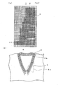
- Figs. 2 show results of the design performed as shown in Fig. 1(c) , thereby Fig. 2(a) shows a pattern appending stitch image 7 and Fig. 2(b) shows a knit product 8, respectively.
- the pattern appending stitch image 7 shown in Fig. 2(a) is obtained by reversal slide deformation, in which the target area 2b shown in Fig. 1(c) is returned in a reversal manner from the specified area 2 shown in Fig. 1(a) into the target area 2a shown in Fig. 1(b) .
- the slide deformation from the specified area 2 into the target area 2a is performed in a manner such that a movement amount is made larger in a stepwise manner in accordance with steps formed on the outer edge 1a from lower courses to upper courses.
- the slide deformation in which the target area 2b shown in Fig. 1(c) is returned so as to be connected to the base area 3 is performed in a manner that the target area 2b shown in Fig. 1(c) is returned by moving each step with the extra knitting 5. This makes it possible to prevent the design of the pattern 4 such as a purl pattern from collapsing.
- a design for a placket 9 of a knit product 8 as shown in Fig. 2(b) can be performed in accordance with the above description by setting the specified area 2 on a design part 9a. If pieces of such partial design are combined, the entire placket 9 can be easily designed and a pattern can be prevented from collapsing even if the extra knitting 5 are appended.
- a case, in which the placket 9 of a neck is designed is described, however in the same manner as Patent Literature 1, a surround of an armhole, or an inner side of a body portion without an outer edge of a knit fabric can be also designed by setting a specified area 2 and including an extra knitting.
- the knit design method is started from step s1, and at step s2, a user inputs fabric knitting information to the knit design apparatus 10 or the like.
- the fabric knitting information information for each knitting stitch, such as a type of knitting stitch is included.
- the knitting stitch image 1 as shown in Fig. 1(a) is displayed.
- the specified area 2 is set in accordance with a specification from a user.
- narrowing positions are collected for each stair changing position on the stair-like outer edge 1a.
- the start position 4f is specified to the target area 2a by the user. Addition of the extra knitting 5 thereafter is performed while accumulating error due to differences in knitting stitch structures such as a type of knitting stitches from one end side closer to the start position 4f to the other end side farther from the start position 4f in the wale direction of the specified area 2, herein error based on the difference between the lengths 1c, 1d is accumulated for each course.
- a difference between the length 1c of the outer edge 1a of the specified area 2 and the length 1d of the specified area 2 in the wale direction is calculated.
- one knitting stitch is assumed to have a size of N mm in the longitudinal direction and M mm in the transversal direction, then the length of the outer edge 1a of the specified area 2a for every two courses is expressed as the following first equation (1).
- Length ⁇ 2 course ⁇ N ⁇ 2 course ⁇ N + 2 stitch ⁇ M ⁇ 2 stitch ⁇ M
- This length 1c beings error based on the difference to the length 1d in the wale direction, and the error is expressed by the following second equation (2).
- Error Length - 2 course ⁇ N / N
- the placket 9 is knitted not only with a purl pattern but also knitted with an interlock knitting, a tubular knitting of half gauge, or the like, and the base area 3 is knitted with plain knitting basically in many cases.
- a size of the knitting stitch in the knitting stitch structure of the placket 9 is reflected to M and N used in the equation (1) and the equation (2), so that appropriate evaluation can be made while including the difference in the knitting stitch structure.
- the difference between the lengths 1c, 1d is obtained as an error on a course basis and is accumulated.
- the reference value corresponds to two courses. If the difference accumulated value becomes larger than the reference value, the extra knitting 5 is appended to the target area 2a at step s10. The extra knitting 5 is appended on a two-course basis as the reference value. The number of courses of the extra knitting 5 is required to be an even number because the knitting position needs to be returned to an original position in reciprocating knitting. If the extra knitting 5 is appended, the difference accumulated value is corrected at step s11. The correction is made in accordance with the number of courses to which the extra knitting 5 is appended.
- step s12 it is judged whether the knitting reaches to the other end of the course of the specified area 2a and the specified area 2a is ended to be knitted. If it is judged that the specified area 2a is not ended to be knitted, the process returns to step s8 and a difference is obtained for a subsequent course.
- step s9 if it is judged that the specified area 2a is ended to be knitted, at step s13, the pattern 4 is designed on the target area 2b to which the extra knitting 5 is added as shown in Fig. 1(c) .
- the slide deformation is returned so as to generate image data corresponding to the pattern appending stitch image 7 as shown in Fig. 2(a) , then knitting data is generated, lastly at step s15, the process is finished.
- the pattern appending stitch image 7 is displayed as an image if the user requests. Portions of the base area 3 corresponding to portions in which the extra knitting 5 have been appended to the target area 2a are displayed as blank lines, however, the blank line can be displayed in a compressed manner by display switching.
- the error due to the difference in the knitting stitch structure is obtained by calculating the difference between the length 1c of the outer edge 1a of the specified area 2 and the length 1d of the specified area 2 in the wale direction.
- the difference is generated as long as the knitted stitches on the specified area 2 are inclined with respect to the knitted stitches on the base area 3 even if the knitting structure and the loop lengths of the knitting stitches are the same between the specified area 2 and the base area 3.
- the difference is accumulated and if the accumulated value becomes larger than the reference value, the extra knitting 5 is appended, so that more extra knitting 5 is appended to a portion on which shape of the specified area 2 is largely changed, such as the outer edge 1a.
- the error due to the difference in the knitting stitch structure is also generated even in a case where the knitting constructions are different between the specified area 2 and the base area 3. For example, shrinkage manners of the knitting stitches after knitted in the wale direction are made different between the knitted fabric of the purl pattern and the knitted fabric of the plain knitting due to the difference in the knitting structure as a structure pattern.
- the error due to the difference in the knitting structure is also accumulated even if the shape of the specified area 2 such as the outer edge 1a is not largely changed, then, if the accumulated value becomes larger than the reference value, the extra knitting 5 is appended, so that distortion generated between the specified area 2 and the base area 3 can be relaxed. Accordingly it is preferable that the extra knitting 5 is appended in consideration of not only the difference of the lengths but also the difference of the knitting structure, even when taking only one of them into consideration, the distortion can be decreased by appending the extra knitting 5.
- Fig. 4 shows a schematic structure of the knit design apparatus 10 as example 2 of another embodiment of the present invention.
- the knit design apparatus 10 is realized by installing programs for executing the knit design method as shown in Figs. 1 to Fig. 3 on a general-purpose computer including a processing device 11, an input device 12, a display device 13, and a storage device 14.
- the processing device 11 includes a data generate means 21, an area partition means 22, an extra knitting append means 23, a pattern design means 24, and an area connect means 25.
- the data generate means 21, the area partition means 22, the extra knitting append means 23, and the pattern design means 24 correspond to step s14, step s4, step s10, and step s13 shown in Fig. 3 , respectively.
- the storage device 14 includes specified area information 26 including various pieces of information relating to the specified area 2, target area information 27 including various pieces of information relating to the target areas 2a, 2b, and a difference accumulated value 28 obtained by accumulating errors expressed by the second equation (2) as the differences.
- the input device 12 also includes a keyboard, a pen tablet, and a connection to communication lines.
- the display device 13 includes an image display device and a print device.
- the storage device 14 includes a mass storage device such as a hard disk and a removable storage medium.
Landscapes
- Engineering & Computer Science (AREA)
- Textile Engineering (AREA)
- Knitting Of Fabric (AREA)
- Knitting Machines (AREA)
Abstract
Description
- The present invention relates to a knit design method and a knit design apparatus, in order to knit fabrics by a flatbed knitting machine of computer control.
- Conventionally, a flatbed knitting machine which is used to produce knit products is controlled by a computer such that selection of knitting needles, run of a carriage, switch of knitting yarns, or the like are performed in accordance with knitting data which is preliminarily prepared. A knit design apparatus is used to prepare the knitting data (for example, see Patent Literature 1).
-
Figs. 5 show a basic way of thinking about a knit design method and an apparatus for knit design, disclosed in thePatent Literature 1, and an outline of a method for designing a pattern to apply the basic way of thinking.Fig. 5(a) shows a knittingstitch image 1 as a base of design for a knitted fabric product. The knitting stitch image is generated, while being displayed on a display device of the apparatus for knit design as an image, in accordance with data for each knitting stitch input by a user. Cells displayed in a screen represent knitting stitches, types of knitting stitches are expressed with specific colors instead of letter symbols for knitting stitch used in hand knitting or hand knitting machine, and color codes corresponding to the colors are input to knitting stitch data. In the flatbed knitting machine, knitting stitches are sequentially formed in a course direction which is transversal, and the courses, which are sequentially formed, are joined to one another in a wale direction which is longitudinal so that a knitted fabric is formed. - It is an object of the method as disclosed in the
Patent Literature 1 to make design easy when the number of knitting stitches in the course direction changes along the wale direction and an outer edge 1a becomes a polygonal line or a curved line that inclines with respect to the wale direction on an end portion of a knitted fabric. In the method, a stripe-like placket provided at the outer edge 1a side is set as a specifiedarea 2, at first. Thespecified area 2 is connected to abase area 3 as a residual of theknitting stitch image 1 through a connecting boundary 1b.Fig. 5(b) shows a state where thespecified area 2 is slid to be deformed into a target area 2a having a simple shape such as a rectangular shape, so as to make design easy. If design is made on the target area 2a, the design is reflected to the placket of thespecified area 2 by returning the slide deformation. - As shown in
Fig. 5(c) , it is considered that as apattern 4 in which, for example, every two courses of front stitches 4a and back stitches 4b, and side edges 4c, 4b provided at both sides thereof are repeatedly formed as a unit so as to make design for a purl pattern of 2 x 2. As shown inFig. 5(d) , thepattern 4 is easily designed on the target area 2a. -
- [Patent Literature 1]
WO2004/088022 A1 - If there is a difference in a knitting stitch structure such as a loop length or a structure of a knitting stitch between the
specified area 2 and thebase area 3 in theknitting stitch image 1, distortion is generated on the connecting boundary 1b due to the difference. Thespecified area 2 has a length along the outer edge 1a and there is a difference between the length of thespecified area 2 and the length of thebase area 3 in the wale direction, so that, if thespecified area 2 and thebase area 3 are knitted to have the same number of courses, distortion is generated. Further, when structures of knitted fabrics are different between thespecified area 2 and thebase area 3, distortion is also generated because shrinkage manners in the wale direction are different. In order to decrease the distortion, extra knitting is performed to add courses corresponding to shortage of the length to the area having a shorter length to be connected. The extra knitting, while trying to knit a knitted fabric and reflecting a result thereof, is performed such that insertion positions and the number thereof are adjusted. Courses to be added may have the same structure such as front stitches or back stitches, in case of a plain knitted fabric, however in case of structure pattern knitted fabric, it is difficult to determine the courses to be added. -
Fig. 6 shows a pattern-appendingstitch image 6, in which theextra knitting 5 added to thespecified area 2, which is the placket on design data formed by returning slide deformation of the target area 2a inFig. 5(d) . In a pattern 4e, by adding the extra knitting 5, a portion on which the number of courses of the front stitches or the back stitches is increased, is generated so that regularity of the purl pattern of 2 x 2 is damaged. In this manner, if theextra knitting 5 is added to the target area 2a on which thepattern 4 has been designed, the pattern design might collapse. - It is an object of the present invention to provide a method and an apparatus for knit design, capable of easily appending an extra knitting and of preventing the pattern design from collapse in a state where the extra knitting is appended.
- The present invention is a knit design method,
which makes it possible to generate knitting data to be used in a flatbed knitting machine, in accordance with a display of a knitting stitch image, in which design of a knitted fabric to be knitted is displayed for each knitting stitch, and an input from a user,
and to target a specified area on design, the specified area is specified by the user in the knitting stitch image, and deformed into a target area having a simple shape based on a predetermined corresponding relationship,
characterized in that the method comprises: - setting an area including a range on which a pattern is displayed as the specified area in the knitting stitch images upon reception of specification from the user, and partitioning the specified area from a base area as an area to which the specified area is to be connected in the knitting stitch image excluding the specified area;
- appending extra knitting to the target area for decreasing distortion generated due to a difference in knitting stitch structure between the specified area and the base area;
- designing a pattern on the target area to which the extra knitting has been appended;
- connecting the target area on which the pattern has been designed to the base area by returning the deformation based on said corresponding relationship; and
- generating said knitting data on the knitted fabric in a state of being connected to the base area by returning deformation of the target area on which the pattern has been designed.
- Further, the present invention is a knit design apparatus, provided with a data generate means for generating knitting data, to be used in a flatbed knitting machine, in accordance with a display of a knitting stitch image in which design of a knitted fabric to be knitted is displayed for each knitting stitch and an input from a user, and able to target a specified area on design, the specified area is specified by the user in the knitting stitch image, and deformed into a target area having a simple shape based on a predetermined corresponding relationship, characterized in that the apparatus comprises:
- an area partition means for partitioning the specified area from a base area as an area to which the specified area is to be connected in the knitting stitch image excluding the specified area, after setting an area including a range on which a pattern is displayed as the specified area in the knitting stitch image upon reception of specification from the user;
- an extra knitting append means for appending extra knitting to the target area to decrease distortion generated due to a difference in knitting stitch structure between the specified area and the base area;
- a pattern design means for designing a pattern on the target area to which the extra knitting has been appended by the extra knitting append means; and
- an area connect means for connecting the target area on which the pattern has been designed by the pattern design means to the base area, by returning the deformation based on said corresponding relationship, wherein
- said data generate means generates said knitting data on the knitted fabric in a state of being connected to the base area by returning deformation of the target area on which the pattern has been designed by the area connect means.
- In the apparatus for knit design according to the present invention, said extra knitting append means sets a difference between a length of an outer edge of the specified area and a length of a portion within said base area to which the specified area is to be connected in a wale direction as said difference in knitting stitch structure.
- In the apparatus for knit design according to the present invention,
said extra knitting append means sets a difference between a shrinkage manner of the knitting stitch on said specified area in the wale direction and a shrinkage manner of the knitting stitch on the a portion within said base area to which the specified area is to be connected in the wale direction as said difference in knitting stitch structure. - In the apparatus for knit design according to the present invention,
said extra knitting append means accumulates said differences from one end side of said specified area to the other end side in the wale direction, and
when the accumulated value of the differences becomes larger than a predetermined reference value, adds a course as said extra knitting. - According to the present invention, extra knitting to decrease distortion generated due to a difference in knitting stitch structures between the specified area and the base area is appended to the target area which is obtained by slide-deforming the specified area in the course direction and has a simple shape, so that the extra knitting can be appended easily. The pattern is designed on the target area having a simple shape to which the extra knitting has been added, so that the pattern can be prevented from collapsing even if the extra knitting is appended.
- Further, according to the present invention, by the extra knitting append means, extra knitting to decrease distortion due to a difference in knitting stitch structures between the specified area and the base area is appended to the target area which is obtained by slide-deforming the specified area in the course direction and has a simple shape. By the pattern design means, the pattern can be designed on the target area having a simple shape to which the extra knitting has been appended.
- In addition, according to the present invention, the extra knitting can be appended to eliminate a difference between lengths in such a case where the outer edge of the specified area is inclined with respect to the wale direction.
- In addition, according to the present invention, the extra knitting can be appended to eliminate a distortion generated by difference between the specified area and the base area in such a case where stitch structure such as a size of knitting stitch is different.
- In addition, according to the present invention, the differences in the knitting stitch structure are accumulated from one end side of the specified area to the other end side in the wale direction, and if an accumulated value of the differences becomes larger than a reference value, a course as the extra knitting is appended, so that a position to which the extra knitting is appended can be determined easily.
-
- [
Fig. 1] Figs. 1 are views showing a basic way of thinking for a knit design method as an example according to the present invention. - [
Fig. 2] Figs. 2 are views showing a pattern appendingstitch image 7 formed according to the way of the thinking shown inFigs. 1 , and a partial front view of aknit product 8 to which the design is applied. - [
Fig. 3] Fig. 3 is a flowchart showing an outline of the method shown inFigs. 1 andFigs. 2 . - [
Fig. 4] Fig. 4 is a block diagram showing a schematic structure of aknit design apparatus 10 as another example of the present invention. - [
Fig. 5] Figs. 5 are views showing a conventional basic way of thinking for a knit design method. - [
Fig. 6] Fig. 6 is a view showing a pattern appendingstitch image 6 when a pattern is designed based on the way of thinking shown inFigs. 5 . - Hereinafter, with reference to
Figs. 1 to Fig. 3 , a knit design method as example 1 of an embodiment of the present invention is described. With reference toFig.4 , aknit design apparatus 10 as another embodiment of the present invention is described. In description of each drawing, there might be cases in which description is made by using reference signs not shown in a drawing itself but shown in a previously described drawing, or same reference signs denote parts corresponding to parts as shown in a previously described drawing so as to omit an overlapping description. -
Fig. 1(a) shows aknitting stitch image 1, in which a specifiedarea 2 of purl knitting is set to have a constant knitting width of ten stitches from an end, for example. With this specification, theknitting stitch image 1 is partitioned into the specifiedarea 2 and abase area 3, in this relation thebase area 3 is a portion excluding the specifiedarea 2 from the knittedknitting stitch image 1 and being connected to the specifiedarea 2.Fig. 1(b) shows a state in which the specifiedarea 2 is slid in a course direction so as to be deformed into a target area 2a having a simple shape, for example, a rectangular shape. Such partition and deformation are performed in the same manner as those shown inFig. 5(a) and Fig. 5(b) , respectively. However, inFig. 1(a) , a length 1c of an outer edge 1a of the specifiedarea 2 and a length 1d of the specifiedarea 2 in a wale direction are taken into consideration. In case when thepattern 4 as shown inFig. 5(c) is designed, a start position 4f is set as shown inFig. 1(b) , then. thepattern 4 is developed from the start position 4f on the target area 2b in which anextra knitting 5 has been appended based on the difference between the length 1c of the outer edge 1a and the length 1d in the wale direction as shown inFig. 1(c) . -
Figs. 2 show results of the design performed as shown inFig. 1(c) , therebyFig. 2(a) shows a pattern appendingstitch image 7 andFig. 2(b) shows aknit product 8, respectively. The pattern appendingstitch image 7 shown inFig. 2(a) is obtained by reversal slide deformation, in which the target area 2b shown inFig. 1(c) is returned in a reversal manner from the specifiedarea 2 shown inFig. 1(a) into the target area 2a shown inFig. 1(b) . The slide deformation from the specifiedarea 2 into the target area 2a is performed in a manner such that a movement amount is made larger in a stepwise manner in accordance with steps formed on the outer edge 1a from lower courses to upper courses. The slide deformation in which the target area 2b shown inFig. 1(c) is returned so as to be connected to thebase area 3 is performed in a manner that the target area 2b shown inFig. 1(c) is returned by moving each step with theextra knitting 5. This makes it possible to prevent the design of thepattern 4 such as a purl pattern from collapsing. - A design for a
placket 9 of aknit product 8 as shown inFig. 2(b) can be performed in accordance with the above description by setting the specifiedarea 2 on a design part 9a. If pieces of such partial design are combined, theentire placket 9 can be easily designed and a pattern can be prevented from collapsing even if theextra knitting 5 are appended. In the present example, a case, in which theplacket 9 of a neck is designed, is described, however in the same manner asPatent Literature 1, a surround of an armhole, or an inner side of a body portion without an outer edge of a knit fabric can be also designed by setting a specifiedarea 2 and including an extra knitting. - As shown in
Fig. 3 , the knit design method is started from step s1, and at step s2, a user inputs fabric knitting information to theknit design apparatus 10 or the like. In the fabric knitting information, information for each knitting stitch, such as a type of knitting stitch is included. At step s3, theknitting stitch image 1 as shown inFig. 1(a) is displayed. At step s4, the specifiedarea 2 is set in accordance with a specification from a user. At step s5, narrowing positions are collected for each stair changing position on the stair-like outer edge 1a. At step s6, the target area 2a having a simple shape, which is obtained by slide-deforming the specifiedarea 2, is displayed. At step s7, the start position 4f is specified to the target area 2a by the user. Addition of theextra knitting 5 thereafter is performed while accumulating error due to differences in knitting stitch structures such as a type of knitting stitches from one end side closer to the start position 4f to the other end side farther from the start position 4f in the wale direction of the specifiedarea 2, herein error based on the difference between the lengths 1c, 1d is accumulated for each course. - At step s8, a difference between the length 1c of the outer edge 1a of the specified
area 2 and the length 1d of the specifiedarea 2 in the wale direction is calculated. In case inserting a narrowing of two stitches for every two courses, concerning the outer edge 1a of the specified area 2a, one knitting stitch is assumed to have a size of N mm in the longitudinal direction and M mm in the transversal direction, then the length of the outer edge 1a of the specified area 2a for every two courses is expressed as the following first equation (1).
This length 1c beings error based on the difference to the length 1d in the wale direction, and the error is expressed by the following second equation (2).
- The
placket 9 is knitted not only with a purl pattern but also knitted with an interlock knitting, a tubular knitting of half gauge, or the like, and thebase area 3 is knitted with plain knitting basically in many cases. A size of the knitting stitch in the knitting stitch structure of theplacket 9 is reflected to M and N used in the equation (1) and the equation (2), so that appropriate evaluation can be made while including the difference in the knitting stitch structure. - At step s8, for example, the difference between the lengths 1c, 1d is obtained as an error on a course basis and is accumulated. At step s9, it is judged whether the accumulated value of the differences becomes larger than the reference value. When the difference is calculated as error on the course basis, the reference value corresponds to two courses. If the difference accumulated value becomes larger than the reference value, the
extra knitting 5 is appended to the target area 2a at step s10. Theextra knitting 5 is appended on a two-course basis as the reference value. The number of courses of theextra knitting 5 is required to be an even number because the knitting position needs to be returned to an original position in reciprocating knitting. If theextra knitting 5 is appended, the difference accumulated value is corrected at step s11. The correction is made in accordance with the number of courses to which theextra knitting 5 is appended. - If it is judged that the difference accumulated value does not become larger than the reference value at step s9, or step s11 is finished, at step s12, it is judged whether the knitting reaches to the other end of the course of the specified area 2a and the specified area 2a is ended to be knitted. If it is judged that the specified area 2a is not ended to be knitted, the process returns to step s8 and a difference is obtained for a subsequent course. At step s9, if it is judged that the specified area 2a is ended to be knitted, at step s13, the
pattern 4 is designed on the target area 2b to which theextra knitting 5 is added as shown inFig. 1(c) . At subsequent step s14, the slide deformation is returned so as to generate image data corresponding to the pattern appendingstitch image 7 as shown inFig. 2(a) , then knitting data is generated, lastly at step s15, the process is finished. The pattern appendingstitch image 7 is displayed as an image if the user requests. Portions of thebase area 3 corresponding to portions in which theextra knitting 5 have been appended to the target area 2a are displayed as blank lines, however, the blank line can be displayed in a compressed manner by display switching. - In the above description, the error due to the difference in the knitting stitch structure is obtained by calculating the difference between the length 1c of the outer edge 1a of the specified
area 2 and the length 1d of the specifiedarea 2 in the wale direction. The difference is generated as long as the knitted stitches on the specifiedarea 2 are inclined with respect to the knitted stitches on thebase area 3 even if the knitting structure and the loop lengths of the knitting stitches are the same between the specifiedarea 2 and thebase area 3. The difference is accumulated and if the accumulated value becomes larger than the reference value, theextra knitting 5 is appended, so that moreextra knitting 5 is appended to a portion on which shape of the specifiedarea 2 is largely changed, such as the outer edge 1a. - The error due to the difference in the knitting stitch structure is also generated even in a case where the knitting constructions are different between the specified
area 2 and thebase area 3. For example, shrinkage manners of the knitting stitches after knitted in the wale direction are made different between the knitted fabric of the purl pattern and the knitted fabric of the plain knitting due to the difference in the knitting structure as a structure pattern. The error due to the difference in the knitting structure is also accumulated even if the shape of the specifiedarea 2 such as the outer edge 1a is not largely changed, then, if the accumulated value becomes larger than the reference value, theextra knitting 5 is appended, so that distortion generated between the specifiedarea 2 and thebase area 3 can be relaxed. Accordingly it is preferable that theextra knitting 5 is appended in consideration of not only the difference of the lengths but also the difference of the knitting structure, even when taking only one of them into consideration, the distortion can be decreased by appending theextra knitting 5. -
Fig. 4 shows a schematic structure of theknit design apparatus 10 as example 2 of another embodiment of the present invention. Theknit design apparatus 10 is realized by installing programs for executing the knit design method as shown inFigs. 1 to Fig. 3 on a general-purpose computer including aprocessing device 11, aninput device 12, adisplay device 13, and astorage device 14. Theprocessing device 11 includes a data generate means 21, an area partition means 22, an extra knitting append means 23, a pattern design means 24, and an area connect means 25. The data generate means 21, the area partition means 22, the extra knitting append means 23, and the pattern design means 24 correspond to step s14, step s4, step s10, and step s13 shown inFig. 3 , respectively. Further, operations corresponding to the area connect means 25 are also included in step s14. Thestorage device 14 includes specified area information 26 including various pieces of information relating to the specifiedarea 2,target area information 27 including various pieces of information relating to the target areas 2a, 2b, and a difference accumulatedvalue 28 obtained by accumulating errors expressed by the second equation (2) as the differences. - The
input device 12 also includes a keyboard, a pen tablet, and a connection to communication lines. Thedisplay device 13 includes an image display device and a print device. Thestorage device 14 includes a mass storage device such as a hard disk and a removable storage medium. -
- 1
- Knitting stitch image
- 1a
- Outer edge
- 1c, 1d
- Length
- 2
- Specified area
- 2a, 2b
- Target area
- 3
- Base area
- 4
- Pattern
- 4f
- Start position
- 5
- Extra knitting
- 8
- Knit product
- 9
- Placket
- 10
- Knit design apparatus
- 21
- Data generate means
- 22
- Area partition means
- 23
- Extra knitting append means
- 24
- Pattern design means
- 25
- Area connect means
Claims (5)
- A knit design method,
which makes it possible to generate knitting data to be used in a flatbed knitting machine, in accordance with a display of a knitting stitch image (1), in which design of a knitted fabric to be knitted is displayed for each knitting stitch, and an input from a user,
and to target a specified area (2) on design, the specified area (2) is specified by the user in the knitting stitch image (1), and deformed into a target area (2a) having a simple shape based on a predetermined corresponding relationship,
characterized in that the method comprises:setting an area including a range on which a pattern is displayed as the specified area (2) in the knitting stitch images (1) upon reception of specification from the user, and partitioning the specified area (2) from a base area (3) as an area to which the specified area (2) is to be connected in the knitting stitch image (1) excluding the specified area (2);appending extra knitting (5) to the target area (2a) for decreasing distortion generated due to a difference in knitting stitch structure between the specified area (2) and the base area (3);designing a pattern (4) on the target area (2b) to which the extra knitting (5) has been appended;connecting the target area (2b) on which the pattern (4) has been designed to the base area (3) by returning the deformation based on said corresponding relationship; andgenerating said knitting data on the knitted fabric in a state of being connected to the base area (3) by returning deformation of the target area (2b) on which the pattern (4) has been designed. - A knit design apparatus (10), provided with a data generate means (21) for generating knitting data, to be used in a flatbed knitting machine, in accordance with a display of a knitting stitch image (1) in which design of a knitted fabric to be knitted is displayed for each knitting stitch and an input from a user, and able to target a specified area (2) on design, the specified area (2) is specified by the user in the knitting stitch image (1), and deformed into a target area (2a) having a simple shape based on a predetermined corresponding relationship,
characterized in that the apparatus comprises:an area partition means (22) for partitioning the specified area (2) from a base area (3) as an areato which the specified area (2) is to be connected in the knitting stitch image (1) excluding the specified area (2), after setting an area including a range on which a pattern is displayed as the specified area (2) in the knitting stitch image (1) upon reception of specification from the user;an extra knitting append means (23) for appending extra knitting (5) to the target area (2a) to decrease distortion generated due to a difference in knitting stitch structure between the specified area (2) and the base area (3);a pattern design means (24) for designing a pattern (4) on the target area (2b) to which the extra knitting (5) has been appended by the extra knitting append means (23); andan area connect means (25) for connecting the target area (2b) on which the pattern (4) has been designed by the pattern design means (24) to the base area (3), by returning the deformation based on said corresponding relationship, whereinsaid data generate means (21) generates said knitting data on the knitted fabric in a state of being connected to the base area (3) by returning deformation of the target area (2b) on which the pattern (4) has been designed by the area connect means (25). - The knit design apparatus (10) according to claim 2, wherein
said extra knitting append means (23) sets a difference between a length of an outer edge (1a) of the specified area (2) and a length of a portion within said base area (3) to which the specified area (2) is to be connected in a wale direction as said difference in knitting stitch structure. - The knit design apparatus (10) according to claim 2, wherein
said extra knitting append means (23) sets a difference between a shrinkage manner of the knitting stitch on said specified area (2) in the wale direction and a shrinkage manner of the knitting stitch on the a portion within said base area (3) to which the specified area (2) is to be connected in the wale direction as said difference in knitting stitch structure. - The knit design apparatus (10) according to claims 3 or 4, wherein said extra knitting append means (23) accumulates said differences from one end side of said specified area (2) to the other end side in the wale direction, and
when the accumulated value of the differences becomes larger than a predetermined reference value, adds a course as said extra knitting (5).
Applications Claiming Priority (1)
| Application Number | Priority Date | Filing Date | Title |
|---|---|---|---|
| JP2011128590A JP5732321B2 (en) | 2011-06-08 | 2011-06-08 | Knit design method and apparatus |
Publications (3)
| Publication Number | Publication Date |
|---|---|
| EP2540888A2 true EP2540888A2 (en) | 2013-01-02 |
| EP2540888A3 EP2540888A3 (en) | 2015-03-04 |
| EP2540888B1 EP2540888B1 (en) | 2016-10-19 |
Family
ID=46319538
Family Applications (1)
| Application Number | Title | Priority Date | Filing Date |
|---|---|---|---|
| EP12004364.1A Active EP2540888B1 (en) | 2011-06-08 | 2012-06-08 | Method and apparatus for knit design |
Country Status (4)
| Country | Link |
|---|---|
| EP (1) | EP2540888B1 (en) |
| JP (1) | JP5732321B2 (en) |
| KR (1) | KR101324525B1 (en) |
| CN (1) | CN102817174B (en) |
Families Citing this family (5)
| Publication number | Priority date | Publication date | Assignee | Title |
|---|---|---|---|---|
| JP6120792B2 (en) * | 2014-03-18 | 2017-04-26 | 株式会社島精機製作所 | Knit design system and knit design method |
| EP3358059B1 (en) * | 2017-02-01 | 2021-11-03 | KARL MAYER STOLL R&D GmbH | Method for producing control data of a warp knitting machine |
| JP2020109223A (en) * | 2018-12-28 | 2020-07-16 | 株式会社島精機製作所 | Production management method and production management system for knit product |
| JP7204583B2 (en) * | 2019-06-12 | 2023-01-16 | 株式会社島精機製作所 | knit design system |
| CN110273220B (en) * | 2019-06-13 | 2021-01-12 | 东华大学 | Construction method of flat-knitted suit pocket parts technology library based on deconstruction method |
Citations (1)
| Publication number | Priority date | Publication date | Assignee | Title |
|---|---|---|---|---|
| WO2004088022A1 (en) | 2003-03-31 | 2004-10-14 | Shima Seiki Manufacturing Ltd. | Method and device for knit design |
Family Cites Families (9)
| Publication number | Priority date | Publication date | Assignee | Title |
|---|---|---|---|---|
| JP2001032153A (en) * | 1999-07-19 | 2001-02-06 | Tsudakoma Corp | Display method of display image in knitted fabric design system and its device |
| DE60238634D1 (en) * | 2001-10-05 | 2011-01-27 | Shima Seiki Mfg | KNITTING DESIGN PROCESS AND UNIT |
| ATE500365T1 (en) * | 2003-04-15 | 2011-03-15 | Shima Seiki Mfg | METHOD AND DEVICE FOR DESIGNING Knitwear |
| JP4366321B2 (en) * | 2005-02-18 | 2009-11-18 | 株式会社島精機製作所 | Knitting product design apparatus and design method, and program thereof |
| EP1956129B1 (en) * | 2005-11-17 | 2016-08-17 | Shima Seiki Manufacturing., Ltd. | Knit design device and knit design method and its program |
| EP2154280B1 (en) * | 2007-04-26 | 2015-06-10 | Shima Seiki Mfg., Ltd | Fabric having yarn-finished portion, treating method therefor, and design device |
| EP2211283B1 (en) * | 2007-09-10 | 2019-07-10 | Shima Seiki Manufacturing., Ltd. | Knitting design device, kintting design method and kintting design program |
| JP2009120987A (en) * | 2007-11-14 | 2009-06-04 | Shima Seiki Mfg Ltd | Method for adjusting number of knitting courses and designing device |
| CN102105627B (en) * | 2008-07-25 | 2012-07-18 | 株式会社岛精机制作所 | Knit design method, knit design device |
-
2011
- 2011-06-08 JP JP2011128590A patent/JP5732321B2/en active Active
-
2012
- 2012-05-25 KR KR1020120055828A patent/KR101324525B1/en active Active
- 2012-05-31 CN CN201210176055.9A patent/CN102817174B/en active Active
- 2012-06-08 EP EP12004364.1A patent/EP2540888B1/en active Active
Patent Citations (1)
| Publication number | Priority date | Publication date | Assignee | Title |
|---|---|---|---|---|
| WO2004088022A1 (en) | 2003-03-31 | 2004-10-14 | Shima Seiki Manufacturing Ltd. | Method and device for knit design |
Also Published As
| Publication number | Publication date |
|---|---|
| JP2012255228A (en) | 2012-12-27 |
| KR101324525B1 (en) | 2013-11-08 |
| JP5732321B2 (en) | 2015-06-10 |
| CN102817174A (en) | 2012-12-12 |
| EP2540888A3 (en) | 2015-03-04 |
| CN102817174B (en) | 2014-08-13 |
| KR20120136287A (en) | 2012-12-18 |
| EP2540888B1 (en) | 2016-10-19 |
Similar Documents
| Publication | Publication Date | Title |
|---|---|---|
| EP2540888B1 (en) | Method and apparatus for knit design | |
| EP0568700B1 (en) | Knit design system and method of making knitting data therefor | |
| KR100625603B1 (en) | Knit design method and device | |
| EP2857566A1 (en) | Knitted fabric with reduced cracks, knitting method therefor, and design system using the knitting method | |
| EP2273002B1 (en) | Knitted fabric designing system | |
| EP1652983A1 (en) | Method and device for knit design and program | |
| EP2921581B1 (en) | Knit design system and knit design method | |
| EP2189560B1 (en) | Device and method for debugging knit design and debug program | |
| KR102319183B1 (en) | Knit design system | |
| EP1849902A1 (en) | Designing device, method and program of knit product | |
| EP2492384B1 (en) | Knit design apparatus and knit design method | |
| EP1614787B1 (en) | Method and device for knit design | |
| CN102619018B (en) | Method and device for designing a shaped knitted article produced on a flat knitting machine | |
| JP2003296027A (en) | Method of optimizing button recognition area on touch panel | |
| EP2211283A1 (en) | Knitting design device, kintting design method and kintting design program | |
| CN111501186B (en) | Design system for knitted fabric | |
| CN102619016A (en) | Method for designing a shaped knitted article produced on a flat knitting machine by means of a design device | |
| CN102575392B (en) | Knit designing device and designing method | |
| EP2955258A1 (en) | Design system for knitted fabric | |
| CN120088211A (en) | A modular definition method and system for knitting movements | |
| KR20190050839A (en) | Shim deployment method, seam placement device and seam placement program | |
| JP2003099473A (en) | Parts registration data development system | |
| JP2018063687A (en) | Design support apparatus for temporary structure and program thereof | |
| JP2018063636A (en) | Design support apparatus for temporary structure and program thereof | |
| JP2017210697A (en) | Method for knitting tubular knitted fabric |
Legal Events
| Date | Code | Title | Description |
|---|---|---|---|
| PUAI | Public reference made under article 153(3) epc to a published international application that has entered the european phase |
Free format text: ORIGINAL CODE: 0009012 |
|
| AK | Designated contracting states |
Kind code of ref document: A2 Designated state(s): AL AT BE BG CH CY CZ DE DK EE ES FI FR GB GR HR HU IE IS IT LI LT LU LV MC MK MT NL NO PL PT RO RS SE SI SK SM TR |
|
| AX | Request for extension of the european patent |
Extension state: BA ME |
|
| PUAL | Search report despatched |
Free format text: ORIGINAL CODE: 0009013 |
|
| AK | Designated contracting states |
Kind code of ref document: A3 Designated state(s): AL AT BE BG CH CY CZ DE DK EE ES FI FR GB GR HR HU IE IS IT LI LT LU LV MC MK MT NL NO PL PT RO RS SE SI SK SM TR |
|
| AX | Request for extension of the european patent |
Extension state: BA ME |
|
| RIC1 | Information provided on ipc code assigned before grant |
Ipc: D04B 37/02 20060101ALI20150129BHEP Ipc: D04B 7/26 20060101AFI20150129BHEP Ipc: D04B 1/12 20060101ALI20150129BHEP Ipc: D04B 15/70 20060101ALI20150129BHEP |
|
| 17P | Request for examination filed |
Effective date: 20150818 |
|
| RBV | Designated contracting states (corrected) |
Designated state(s): AL AT BE BG CH CY CZ DE DK EE ES FI FR GB GR HR HU IE IS IT LI LT LU LV MC MK MT NL NO PL PT RO RS SE SI SK SM TR |
|
| GRAP | Despatch of communication of intention to grant a patent |
Free format text: ORIGINAL CODE: EPIDOSNIGR1 |
|
| INTG | Intention to grant announced |
Effective date: 20160429 |
|
| GRAS | Grant fee paid |
Free format text: ORIGINAL CODE: EPIDOSNIGR3 |
|
| GRAA | (expected) grant |
Free format text: ORIGINAL CODE: 0009210 |
|
| AK | Designated contracting states |
Kind code of ref document: B1 Designated state(s): AL AT BE BG CH CY CZ DE DK EE ES FI FR GB GR HR HU IE IS IT LI LT LU LV MC MK MT NL NO PL PT RO RS SE SI SK SM TR |
|
| REG | Reference to a national code |
Ref country code: GB Ref legal event code: FG4D |
|
| REG | Reference to a national code |
Ref country code: CH Ref legal event code: EP |
|
| REG | Reference to a national code |
Ref country code: AT Ref legal event code: REF Ref document number: 838430 Country of ref document: AT Kind code of ref document: T Effective date: 20161115 |
|
| REG | Reference to a national code |
Ref country code: IE Ref legal event code: FG4D |
|
| REG | Reference to a national code |
Ref country code: DE Ref legal event code: R096 Ref document number: 602012024225 Country of ref document: DE |
|
| REG | Reference to a national code |
Ref country code: NL Ref legal event code: MP Effective date: 20161019 |
|
| REG | Reference to a national code |
Ref country code: LT Ref legal event code: MG4D |
|
| PG25 | Lapsed in a contracting state [announced via postgrant information from national office to epo] |
Ref country code: LV Free format text: LAPSE BECAUSE OF FAILURE TO SUBMIT A TRANSLATION OF THE DESCRIPTION OR TO PAY THE FEE WITHIN THE PRESCRIBED TIME-LIMIT Effective date: 20161019 |
|
| REG | Reference to a national code |
Ref country code: AT Ref legal event code: MK05 Ref document number: 838430 Country of ref document: AT Kind code of ref document: T Effective date: 20161019 |
|
| PG25 | Lapsed in a contracting state [announced via postgrant information from national office to epo] |
Ref country code: GR Free format text: LAPSE BECAUSE OF FAILURE TO SUBMIT A TRANSLATION OF THE DESCRIPTION OR TO PAY THE FEE WITHIN THE PRESCRIBED TIME-LIMIT Effective date: 20170120 Ref country code: LT Free format text: LAPSE BECAUSE OF FAILURE TO SUBMIT A TRANSLATION OF THE DESCRIPTION OR TO PAY THE FEE WITHIN THE PRESCRIBED TIME-LIMIT Effective date: 20161019 Ref country code: NO Free format text: LAPSE BECAUSE OF FAILURE TO SUBMIT A TRANSLATION OF THE DESCRIPTION OR TO PAY THE FEE WITHIN THE PRESCRIBED TIME-LIMIT Effective date: 20170119 Ref country code: SE Free format text: LAPSE BECAUSE OF FAILURE TO SUBMIT A TRANSLATION OF THE DESCRIPTION OR TO PAY THE FEE WITHIN THE PRESCRIBED TIME-LIMIT Effective date: 20161019 |
|
| PG25 | Lapsed in a contracting state [announced via postgrant information from national office to epo] |
Ref country code: NL Free format text: LAPSE BECAUSE OF FAILURE TO SUBMIT A TRANSLATION OF THE DESCRIPTION OR TO PAY THE FEE WITHIN THE PRESCRIBED TIME-LIMIT Effective date: 20161019 Ref country code: PT Free format text: LAPSE BECAUSE OF FAILURE TO SUBMIT A TRANSLATION OF THE DESCRIPTION OR TO PAY THE FEE WITHIN THE PRESCRIBED TIME-LIMIT Effective date: 20170220 Ref country code: HR Free format text: LAPSE BECAUSE OF FAILURE TO SUBMIT A TRANSLATION OF THE DESCRIPTION OR TO PAY THE FEE WITHIN THE PRESCRIBED TIME-LIMIT Effective date: 20161019 Ref country code: RS Free format text: LAPSE BECAUSE OF FAILURE TO SUBMIT A TRANSLATION OF THE DESCRIPTION OR TO PAY THE FEE WITHIN THE PRESCRIBED TIME-LIMIT Effective date: 20161019 Ref country code: FI Free format text: LAPSE BECAUSE OF FAILURE TO SUBMIT A TRANSLATION OF THE DESCRIPTION OR TO PAY THE FEE WITHIN THE PRESCRIBED TIME-LIMIT Effective date: 20161019 Ref country code: ES Free format text: LAPSE BECAUSE OF FAILURE TO SUBMIT A TRANSLATION OF THE DESCRIPTION OR TO PAY THE FEE WITHIN THE PRESCRIBED TIME-LIMIT Effective date: 20161019 Ref country code: IS Free format text: LAPSE BECAUSE OF FAILURE TO SUBMIT A TRANSLATION OF THE DESCRIPTION OR TO PAY THE FEE WITHIN THE PRESCRIBED TIME-LIMIT Effective date: 20170219 Ref country code: AT Free format text: LAPSE BECAUSE OF FAILURE TO SUBMIT A TRANSLATION OF THE DESCRIPTION OR TO PAY THE FEE WITHIN THE PRESCRIBED TIME-LIMIT Effective date: 20161019 Ref country code: PL Free format text: LAPSE BECAUSE OF FAILURE TO SUBMIT A TRANSLATION OF THE DESCRIPTION OR TO PAY THE FEE WITHIN THE PRESCRIBED TIME-LIMIT Effective date: 20161019 Ref country code: BE Free format text: LAPSE BECAUSE OF FAILURE TO SUBMIT A TRANSLATION OF THE DESCRIPTION OR TO PAY THE FEE WITHIN THE PRESCRIBED TIME-LIMIT Effective date: 20161019 |
|
| REG | Reference to a national code |
Ref country code: DE Ref legal event code: R097 Ref document number: 602012024225 Country of ref document: DE |
|
| PG25 | Lapsed in a contracting state [announced via postgrant information from national office to epo] |
Ref country code: RO Free format text: LAPSE BECAUSE OF FAILURE TO SUBMIT A TRANSLATION OF THE DESCRIPTION OR TO PAY THE FEE WITHIN THE PRESCRIBED TIME-LIMIT Effective date: 20161019 Ref country code: SK Free format text: LAPSE BECAUSE OF FAILURE TO SUBMIT A TRANSLATION OF THE DESCRIPTION OR TO PAY THE FEE WITHIN THE PRESCRIBED TIME-LIMIT Effective date: 20161019 Ref country code: CZ Free format text: LAPSE BECAUSE OF FAILURE TO SUBMIT A TRANSLATION OF THE DESCRIPTION OR TO PAY THE FEE WITHIN THE PRESCRIBED TIME-LIMIT Effective date: 20161019 Ref country code: DK Free format text: LAPSE BECAUSE OF FAILURE TO SUBMIT A TRANSLATION OF THE DESCRIPTION OR TO PAY THE FEE WITHIN THE PRESCRIBED TIME-LIMIT Effective date: 20161019 Ref country code: EE Free format text: LAPSE BECAUSE OF FAILURE TO SUBMIT A TRANSLATION OF THE DESCRIPTION OR TO PAY THE FEE WITHIN THE PRESCRIBED TIME-LIMIT Effective date: 20161019 |
|
| PLBE | No opposition filed within time limit |
Free format text: ORIGINAL CODE: 0009261 |
|
| STAA | Information on the status of an ep patent application or granted ep patent |
Free format text: STATUS: NO OPPOSITION FILED WITHIN TIME LIMIT |
|
| PG25 | Lapsed in a contracting state [announced via postgrant information from national office to epo] |
Ref country code: BG Free format text: LAPSE BECAUSE OF FAILURE TO SUBMIT A TRANSLATION OF THE DESCRIPTION OR TO PAY THE FEE WITHIN THE PRESCRIBED TIME-LIMIT Effective date: 20170119 Ref country code: SM Free format text: LAPSE BECAUSE OF FAILURE TO SUBMIT A TRANSLATION OF THE DESCRIPTION OR TO PAY THE FEE WITHIN THE PRESCRIBED TIME-LIMIT Effective date: 20161019 |
|
| 26N | No opposition filed |
Effective date: 20170720 |
|
| PG25 | Lapsed in a contracting state [announced via postgrant information from national office to epo] |
Ref country code: SI Free format text: LAPSE BECAUSE OF FAILURE TO SUBMIT A TRANSLATION OF THE DESCRIPTION OR TO PAY THE FEE WITHIN THE PRESCRIBED TIME-LIMIT Effective date: 20161019 |
|
| PG25 | Lapsed in a contracting state [announced via postgrant information from national office to epo] |
Ref country code: MC Free format text: LAPSE BECAUSE OF FAILURE TO SUBMIT A TRANSLATION OF THE DESCRIPTION OR TO PAY THE FEE WITHIN THE PRESCRIBED TIME-LIMIT Effective date: 20161019 |
|
| REG | Reference to a national code |
Ref country code: CH Ref legal event code: PL |
|
| GBPC | Gb: european patent ceased through non-payment of renewal fee |
Effective date: 20170608 |
|
| REG | Reference to a national code |
Ref country code: IE Ref legal event code: MM4A |
|
| REG | Reference to a national code |
Ref country code: FR Ref legal event code: ST Effective date: 20180228 |
|
| PG25 | Lapsed in a contracting state [announced via postgrant information from national office to epo] |
Ref country code: LI Free format text: LAPSE BECAUSE OF NON-PAYMENT OF DUE FEES Effective date: 20170630 Ref country code: LU Free format text: LAPSE BECAUSE OF NON-PAYMENT OF DUE FEES Effective date: 20170608 Ref country code: IE Free format text: LAPSE BECAUSE OF NON-PAYMENT OF DUE FEES Effective date: 20170608 Ref country code: GB Free format text: LAPSE BECAUSE OF NON-PAYMENT OF DUE FEES Effective date: 20170608 Ref country code: CH Free format text: LAPSE BECAUSE OF NON-PAYMENT OF DUE FEES Effective date: 20170630 |
|
| PG25 | Lapsed in a contracting state [announced via postgrant information from national office to epo] |
Ref country code: FR Free format text: LAPSE BECAUSE OF NON-PAYMENT OF DUE FEES Effective date: 20170630 |
|
| PG25 | Lapsed in a contracting state [announced via postgrant information from national office to epo] |
Ref country code: MT Free format text: LAPSE BECAUSE OF NON-PAYMENT OF DUE FEES Effective date: 20170608 |
|
| PG25 | Lapsed in a contracting state [announced via postgrant information from national office to epo] |
Ref country code: HU Free format text: LAPSE BECAUSE OF FAILURE TO SUBMIT A TRANSLATION OF THE DESCRIPTION OR TO PAY THE FEE WITHIN THE PRESCRIBED TIME-LIMIT; INVALID AB INITIO Effective date: 20120608 |
|
| PG25 | Lapsed in a contracting state [announced via postgrant information from national office to epo] |
Ref country code: CY Free format text: LAPSE BECAUSE OF NON-PAYMENT OF DUE FEES Effective date: 20161019 |
|
| PG25 | Lapsed in a contracting state [announced via postgrant information from national office to epo] |
Ref country code: MK Free format text: LAPSE BECAUSE OF FAILURE TO SUBMIT A TRANSLATION OF THE DESCRIPTION OR TO PAY THE FEE WITHIN THE PRESCRIBED TIME-LIMIT Effective date: 20161019 |
|
| PG25 | Lapsed in a contracting state [announced via postgrant information from national office to epo] |
Ref country code: TR Free format text: LAPSE BECAUSE OF FAILURE TO SUBMIT A TRANSLATION OF THE DESCRIPTION OR TO PAY THE FEE WITHIN THE PRESCRIBED TIME-LIMIT Effective date: 20161019 |
|
| PG25 | Lapsed in a contracting state [announced via postgrant information from national office to epo] |
Ref country code: AL Free format text: LAPSE BECAUSE OF FAILURE TO SUBMIT A TRANSLATION OF THE DESCRIPTION OR TO PAY THE FEE WITHIN THE PRESCRIBED TIME-LIMIT Effective date: 20161019 |
|
| PGFP | Annual fee paid to national office [announced via postgrant information from national office to epo] |
Ref country code: DE Payment date: 20250402 Year of fee payment: 14 |
|
| PGFP | Annual fee paid to national office [announced via postgrant information from national office to epo] |
Ref country code: IT Payment date: 20250522 Year of fee payment: 14 |