EP2540860A2 - Planetary manipulator for PVD coating system - Google Patents
Planetary manipulator for PVD coating system Download PDFInfo
- Publication number
- EP2540860A2 EP2540860A2 EP12173821A EP12173821A EP2540860A2 EP 2540860 A2 EP2540860 A2 EP 2540860A2 EP 12173821 A EP12173821 A EP 12173821A EP 12173821 A EP12173821 A EP 12173821A EP 2540860 A2 EP2540860 A2 EP 2540860A2
- Authority
- EP
- European Patent Office
- Prior art keywords
- driveshaft
- gear
- coating
- sun gear
- planetary
- Prior art date
- Legal status (The legal status is an assumption and is not a legal conclusion. Google has not performed a legal analysis and makes no representation as to the accuracy of the status listed.)
- Granted
Links
Images

Classifications
-
- C—CHEMISTRY; METALLURGY
- C23—COATING METALLIC MATERIAL; COATING MATERIAL WITH METALLIC MATERIAL; CHEMICAL SURFACE TREATMENT; DIFFUSION TREATMENT OF METALLIC MATERIAL; COATING BY VACUUM EVAPORATION, BY SPUTTERING, BY ION IMPLANTATION OR BY CHEMICAL VAPOUR DEPOSITION, IN GENERAL; INHIBITING CORROSION OF METALLIC MATERIAL OR INCRUSTATION IN GENERAL
- C23C—COATING METALLIC MATERIAL; COATING MATERIAL WITH METALLIC MATERIAL; SURFACE TREATMENT OF METALLIC MATERIAL BY DIFFUSION INTO THE SURFACE, BY CHEMICAL CONVERSION OR SUBSTITUTION; COATING BY VACUUM EVAPORATION, BY SPUTTERING, BY ION IMPLANTATION OR BY CHEMICAL VAPOUR DEPOSITION, IN GENERAL
- C23C14/00—Coating by vacuum evaporation, by sputtering or by ion implantation of the coating forming material
- C23C14/22—Coating by vacuum evaporation, by sputtering or by ion implantation of the coating forming material characterised by the process of coating
- C23C14/50—Substrate holders
- C23C14/505—Substrate holders for rotation of the substrates
-
- B—PERFORMING OPERATIONS; TRANSPORTING
- B25—HAND TOOLS; PORTABLE POWER-DRIVEN TOOLS; MANIPULATORS
- B25J—MANIPULATORS; CHAMBERS PROVIDED WITH MANIPULATION DEVICES
- B25J1/00—Manipulators positioned in space by hand
-
- B—PERFORMING OPERATIONS; TRANSPORTING
- B25—HAND TOOLS; PORTABLE POWER-DRIVEN TOOLS; MANIPULATORS
- B25J—MANIPULATORS; CHAMBERS PROVIDED WITH MANIPULATION DEVICES
- B25J11/00—Manipulators not otherwise provided for
- B25J11/0075—Manipulators for painting or coating
-
- B—PERFORMING OPERATIONS; TRANSPORTING
- B25—HAND TOOLS; PORTABLE POWER-DRIVEN TOOLS; MANIPULATORS
- B25J—MANIPULATORS; CHAMBERS PROVIDED WITH MANIPULATION DEVICES
- B25J9/00—Program-controlled manipulators
- B25J9/10—Program-controlled manipulators characterised by positioning means for manipulator elements
- B25J9/102—Gears specially adapted therefor, e.g. reduction gears
-
- F—MECHANICAL ENGINEERING; LIGHTING; HEATING; WEAPONS; BLASTING
- F16—ENGINEERING ELEMENTS AND UNITS; GENERAL MEASURES FOR PRODUCING AND MAINTAINING EFFECTIVE FUNCTIONING OF MACHINES OR INSTALLATIONS; THERMAL INSULATION IN GENERAL
- F16H—GEARING
- F16H57/00—General details of gearing
- F16H57/02—Gearboxes; Mounting gearing therein
- F16H57/033—Series gearboxes, e.g. gearboxes based on the same design being available in different sizes or gearboxes using a combination of several standardised units
-
- F—MECHANICAL ENGINEERING; LIGHTING; HEATING; WEAPONS; BLASTING
- F16—ENGINEERING ELEMENTS AND UNITS; GENERAL MEASURES FOR PRODUCING AND MAINTAINING EFFECTIVE FUNCTIONING OF MACHINES OR INSTALLATIONS; THERMAL INSULATION IN GENERAL
- F16L—PIPES; JOINTS OR FITTINGS FOR PIPES; SUPPORTS FOR PIPES, CABLES OR PROTECTIVE TUBING; MEANS FOR THERMAL INSULATION IN GENERAL
- F16L35/00—Special arrangements used in connection with end fittings of hoses, e.g. safety or protecting devices
-
- F—MECHANICAL ENGINEERING; LIGHTING; HEATING; WEAPONS; BLASTING
- F01—MACHINES OR ENGINES IN GENERAL; ENGINE PLANTS IN GENERAL; STEAM ENGINES
- F01D—NON-POSITIVE DISPLACEMENT MACHINES OR ENGINES, e.g. STEAM TURBINES
- F01D25/00—Component parts, details, or accessories, not provided for in, or of interest apart from, other groups
- F01D25/28—Supporting or mounting arrangements, e.g. for turbine casing
- F01D25/285—Temporary support structures, e.g. for testing, assembling, installing, repairing; Assembly methods using such structures
-
- F—MECHANICAL ENGINEERING; LIGHTING; HEATING; WEAPONS; BLASTING
- F01—MACHINES OR ENGINES IN GENERAL; ENGINE PLANTS IN GENERAL; STEAM ENGINES
- F01D—NON-POSITIVE DISPLACEMENT MACHINES OR ENGINES, e.g. STEAM TURBINES
- F01D5/00—Blades; Blade-carrying members; Heating, heat-insulating, cooling or antivibration means on the blades or the members
- F01D5/12—Blades
- F01D5/28—Selecting particular materials; Particular measures relating thereto; Measures against erosion or corrosion
- F01D5/288—Protective coatings for blades
-
- F—MECHANICAL ENGINEERING; LIGHTING; HEATING; WEAPONS; BLASTING
- F05—INDEXING SCHEMES RELATING TO ENGINES OR PUMPS IN VARIOUS SUBCLASSES OF CLASSES F01-F04
- F05D—INDEXING SCHEME FOR ASPECTS RELATING TO NON-POSITIVE-DISPLACEMENT MACHINES OR ENGINES, GAS-TURBINES OR JET-PROPULSION PLANTS
- F05D2230/00—Manufacture
- F05D2230/30—Manufacture with deposition of material
- F05D2230/31—Layer deposition
-
- F—MECHANICAL ENGINEERING; LIGHTING; HEATING; WEAPONS; BLASTING
- F16—ENGINEERING ELEMENTS AND UNITS; GENERAL MEASURES FOR PRODUCING AND MAINTAINING EFFECTIVE FUNCTIONING OF MACHINES OR INSTALLATIONS; THERMAL INSULATION IN GENERAL
- F16H—GEARING
- F16H1/00—Toothed gearings for conveying rotary motion
- F16H1/28—Toothed gearings for conveying rotary motion with gears having orbital motion
-
- F—MECHANICAL ENGINEERING; LIGHTING; HEATING; WEAPONS; BLASTING
- F16—ENGINEERING ELEMENTS AND UNITS; GENERAL MEASURES FOR PRODUCING AND MAINTAINING EFFECTIVE FUNCTIONING OF MACHINES OR INSTALLATIONS; THERMAL INSULATION IN GENERAL
- F16H—GEARING
- F16H35/00—Gearings or mechanisms with other special functional features
Definitions
- the present invention relates to coating systems for applying coatings to workpieces, and more particularly to coating systems that include a manipulator having planetary gearing.
- manipulators can be used to move the workpiece within a stream, plume or cloud of coating material.
- Such manipulators allow more even coating thickness distribution on various surfaces of workpieces, especially workpieces with relatively complex geometries and hard-to-reach (e.g., non-line-of-sight) areas.
- Gear-driven manipulators exist, including those with gear-driven arms that rotate and move upward and downward at up to +/- 45° in a "butterfly" movement to provide one complete axis of rotation and one partial axis of rotation.
- Gas turbine engines include numerous components with a variety of coatings.
- gas turbine engines often include vane segments, such as "doublets" with a pair of airfoils extending between inner and outer platforms.
- doublets can include thermal barrier coatings (TBCs) made of ceramics or other materials, as well as environmental or other coatings.
- TBCs thermal barrier coatings
- the configuration of typical vane doublets with highly contoured end walls can make coating uniform coating distribution difficult, including in the throat area between the airfoils.
- a coating system includes a coating source and a planetary manipulator assembly that includes a first driveshaft capable of receiving rotational input, a sun gear rotationally fixed to the first driveshaft, a planetary gear engaged with the sun gear, a second driveshaft rotationally fixed to the planetary gear such that torque is transmitted from the sun gear to the planetary gear, a support shaft operatively engaged with the second driveshaft, a carrier body supporting the planetary gear relative to the sun gear, a third driveshaft capable of receiving rotational input, and a drive gear rotationally fixed to the third driveshaft.
- the support shaft is arranged substantially perpendicular to the second driveshaft.
- the carrier body is rotatable by the drive gear about a common axis with the sun gear, and rotation of the carrier body rotates the planetary gear and the second driveshaft about the sun gear.
- a coating system comprising: a planetary manipulator assembly comprising: a first driveshaft capable of receiving rotational input; a sun gear rotationally fixed to the first driveshaft for rotation therewith; a planetary gear engaged with the sun gear; a second driveshaft rotationally fixed to the planetary gear for rotation therewith, such that such that torque is transmitted from the sun gear to the planetary gear to rotate the second driveshaft, wherein the first driveshaft and the second driveshaft are arranged parallel to each other; a support shaft operatively engaged with the second driveshaft, wherein the support shaft is arranged substantially perpendicular to the second driveshaft; bevel gears that provide a rotational engagement between the second driveshaft and the support shaft; a carrier body supporting the planetary gear relative to the sun gear, wherein the carrier body is rotatable about a common axis with the sun gear, and wherein rotation of the carrier body rotates the planetary gear and the second driveshaft about the sun gear; a third driveshaft capable of receiving rotational input
- a method of manipulating a workpiece for coating application comprising: rotating a sun gear about a first axis; rotating a planetary gear and associated shaft using the sun gear; rotating a support shaft using the planetary gear and the associated shaft, wherein the support shaft rotates about a second axis that is perpendicular to the first axis; rotating a carrier body to move the planetary gear and the associated shaft about a circumference of the sun gear; carrying a workpiece at a distal end of the support shaft; and delivering a coating material to the workpiece.
- FIG. 1 is a schematic illustration of an embodiment of a coating application system according to the present invention.
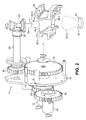
- FIG. 2 is a perspective view of a portion of the coating application system of FIG. 1 .
- a workpiece manipulator assembly that utilizes planetary movement to provide pseudo- or near-random part movement to provide desirable coating distribution.
- the system of the present invention can be utilized to provide electron beam physical vapor deposition (EB-PVD) application of thermal barrier coatings (TBCs) to gas turbine engine components, as well as to provide a variety of other types of coating materials with a variety of different coating application methods to desired workpieces.
- EB-PVD electron beam physical vapor deposition
- TBCs thermal barrier coatings
- FIG. 1 is a schematic illustration of an embodiment of a coating application system 10
- FIG. 2 is a perspective view of a portion of the coating application system 10.
- the system 10 includes a manipulator assembly 11 that includes a driveshaft 12, a sun gear 14, a planetary gear 16, a driveshaft 18, bevel gears 20 and 22, a support shaft (or spindle) 24, a fixture 26, a driveshaft 28, a drive gear 30, a carrier gear 32, a carrier body 34, and a housing 36.
- the manipulator assembly 11 can be used to hold and manipulate a workpiece 38 (e.g., a gas turbine engine vane doublet) for application of a coating delivered by a coating source 40.
- a workpiece 38 e.g., a gas turbine engine vane doublet
- Portions or all of the manipulator assembly 11, workpiece 38 and the coating source 40 can be positioned within an enclosure 42.
- a geartrain defined by the manipulator assembly 11 can be configured as follows.
- the driveshaft 12 is rotationally fixed to the sun gear 14 for common rotation about an axis A.
- the sun gear 14 is engaged with the planetary gear 16, such that rotation of the sun gear 14 rotates the planetary gear 16.
- a gear ratio of approximately 2.5:1 can be used between the planetary gear 16 and the sun gear 14, though any desired gear ratio can be used in alternative embodiments.
- the driveshaft 18 is rotationally fixed to the planetary gear 16 and rotates with the planetary gear 16.
- the driveshaft 18 is arranged parallel to the driveshaft 12.
- the bevel gear 20 is fixed to the driveshaft 18, and the bevel gear 22 is fixed to the support shaft 24.
- the bevel gears 20 and 22 engage each other to transmit torque between the driveshaft 18 and the support shaft 24.
- the fixture 26 is supported at a distal end of the support shaft 24, opposite the bevel gear 22.
- the shaft 28 is arranged parallel and adjacent to the shaft 12.
- the drive gear 30 is rotationally fixed to the shaft 28 for common rotation.
- the carrier gear 32 can be rotatably supported on the shaft 12 about the axis A, with the carrier gear 32 configured to allow rotation independent of the shaft 12.
- the drive gear 30 and the carrier gear 32 engage each other to transmit torque.
- the carrier gear 32 is rotationally fixed to the carrier body 34.
- the driveshaft 12 can pass through the carrier body 34, but the carrier body 34 is rotationally independent from the driveshaft 12.
- the planetary gear 16 is supported and carried by the carrier body 34, though the planetary gear 16 can rotate relative to the carrier body 34. Rotation of the carrier body 34 about the axis A causes the planetary gear 16 to travel about a circumference of the sun gear 14 (about the axis A).
- the housing 36 can enclose components of the manipulator assembly 11 to shield them from coating materials and help prevent coating material accumulation on sensitive gears, etc. of the assembly 11.
- the fixture 26 can engage and retain at least one workpiece 38, and can have any suitable configuration to secure one or more desired workpieces.
- the workpiece 38 is shown exploded relative to the support shaft 24, and the fixture 26 is omitted for simplicity.
- the workpiece 38 is a gas turbine engine vane segment "doublet" having a pair of airfoils 38-1 and 38-2 extending between an inner platform 38-3 and an outer platform 38-4.
- the fixture 26 supports the vane segment workpiece 38 with the support shaft 24 positioned at a midpoint located in between the airfoils 38-1 and 38-2 and in between the inner and outer platforms 38-3 and 38-4.
- the workpiece 38 can be positioned relative to the support shaft 24 to provide optimal line-of-sight positioning relative to one or more axes of movement and a coating source 40.
- the coating source 40 can be an EB-PVD assembly with a material pool 40-1 that can produce a coating vapor plume 40-2 directed toward the workpiece 38. Any conventional EB-PVD assembly can be used.
- the coating plume 40-2 can extend toward the workpiece 38 in a direction generally perpendicular to the axis A and aligned with a plane in which the support arm 24 moves, in order to deliver vaporized coating material to the workpiece 38.
- the EB-PVD system described herein is but one example of a configuration of the coating source 40, and in alternative embodiment other types of coating delivery techniques and systems can be utilized.
- the enclosure 42 can be provided to surround at least portions of the manipulator assembly 11, the workpiece 38 and the coating source 40. It should be recognized that portions of those components, particularly portions of the manipulator assembly 11 and the coating source 40 can extend outside the enclosure 42.
- torque can be selectively provided to the driveshafts 12 and 28 to provide rotational input to the manipulation assembly 11.
- One or more conventional motors or other mechanisms can be used to provide torque input to the driveshafts 12 and 28, which can be rotated independently at the same speed or different speeds.
- the driveshaft 12 rotates the sun gear 14 about the axis A.
- the sun gear 14 transmits torque to the planetary gear 16, which causes the associated driveshaft 18 to rotate.
- the bevel gears 20 and 22 transmit torque from the shaft 18 to the support shaft 24, which rotates about an axis B perpendicular to the axis A.
- the driveshaft 28 rotates the drive gear 30, which engages the carrier gear 32 thereby rotating the carrier body 34.
- the planetary gear 16 and the driveshaft 18, as well as the support shaft 24 and the workpiece 38 carried at the end of the support shaft 24, are moved around the circumference of the sun gear 14 by rotation of the carrier body 34 about the axis A.
- Coating material can be delivered from the coating source 40 while the workpiece 38 is manipulated by the manipulation assembly 11. Manipulation of the assembly 11 tends to cause end-to-end rotational movement of the inner and outer platforms 38-3 and 38-4 of the workpiece 38 about the axis B, with additional rotation (including orbital movement) in relation to the axis A.
- the movement of the workpiece 38 allows the coating plume 40-2 to tend to focus on the airfoils 38-1 and 38-2 and adjacent surfaces of the platforms 38-3 and 38-4 while reducing the amount of coating directed to non-flowpath-boundary surfaces of the platforms 38-3 and 38-4.
- the particular orientation of the workpiece 38 relative to the coating plume 40-2 shown in FIG. 2 would only occur momentarily during operation.
- the movement of the workpiece 38 while the manipulator assembly 11 operates approaches or approximates random movement.
- manipulation movement can be adjusted to include dwell times, during which movement of the workpiece 38 is slowed or stopped to increase expose to the coating plume 40-2 at a particular orientation.
- workpiece orientation on a given support shaft can be adjusted as desired for particular applications to optimize coating thicknesses and coating microstructure (e.g., vertical columns) in difficult to coat areas.
- Workpiece orientation is driven in large part by workpiece configuration, and the manipulation angles and dwell positions can be prioritized by the amount of coating need in each area on a particular part (e.g., where more thermal protection is needed, more TBC is applied). For instance, in some embodiments, more coating may be applied to an inner platform than an outer platform of a gas turbine engine vane segment because the inner platform runs hotter than the outer platform during engine operation.
- any relative terms or terms of degree used herein such as “substantially”, “approximately”, “essentially”, “generally” and the like, should be interpreted in accordance with and subject to any applicable definitions or limits expressly stated herein. In all instances, any relative terms or terms of degree used herein should be interpreted to broadly encompass any relevant disclosed embodiments as well as such ranges or variations as would be understood by a person of ordinary skill in the art in view of the entirety of the present disclosure, such as to encompass ordinary manufacturing tolerance variations and the like.
Landscapes
- Engineering & Computer Science (AREA)
- Mechanical Engineering (AREA)
- Chemical & Material Sciences (AREA)
- Robotics (AREA)
- General Engineering & Computer Science (AREA)
- Materials Engineering (AREA)
- Chemical Kinetics & Catalysis (AREA)
- Metallurgy (AREA)
- Organic Chemistry (AREA)
- Spray Control Apparatus (AREA)
- Physical Vapour Deposition (AREA)
- Manipulator (AREA)
- Retarders (AREA)
Abstract
Description
- The present invention relates to coating systems for applying coatings to workpieces, and more particularly to coating systems that include a manipulator having planetary gearing.
- In order to apply coatings to workpieces with desirable coating distribution, manipulators can be used to move the workpiece within a stream, plume or cloud of coating material. Such manipulators allow more even coating thickness distribution on various surfaces of workpieces, especially workpieces with relatively complex geometries and hard-to-reach (e.g., non-line-of-sight) areas. Gear-driven manipulators exist, including those with gear-driven arms that rotate and move upward and downward at up to +/- 45° in a "butterfly" movement to provide one complete axis of rotation and one partial axis of rotation.
- Gas turbine engines include numerous components with a variety of coatings. For example, gas turbine engines often include vane segments, such as "doublets" with a pair of airfoils extending between inner and outer platforms. Such doublets can include thermal barrier coatings (TBCs) made of ceramics or other materials, as well as environmental or other coatings. The configuration of typical vane doublets with highly contoured end walls can make coating uniform coating distribution difficult, including in the throat area between the airfoils.
- Therefore, it is desired to provide an alternative coating system having an alternative workpiece manipulator.
- A coating system according to the present invention includes a coating source and a planetary manipulator assembly that includes a first driveshaft capable of receiving rotational input, a sun gear rotationally fixed to the first driveshaft, a planetary gear engaged with the sun gear, a second driveshaft rotationally fixed to the planetary gear such that torque is transmitted from the sun gear to the planetary gear, a support shaft operatively engaged with the second driveshaft, a carrier body supporting the planetary gear relative to the sun gear, a third driveshaft capable of receiving rotational input, and a drive gear rotationally fixed to the third driveshaft. The support shaft is arranged substantially perpendicular to the second driveshaft. The carrier body is rotatable by the drive gear about a common axis with the sun gear, and rotation of the carrier body rotates the planetary gear and the second driveshaft about the sun gear.
- According to another aspect of the present invention, there is provided a coating system comprising: a planetary manipulator assembly comprising: a first driveshaft capable of receiving rotational input; a sun gear rotationally fixed to the first driveshaft for rotation therewith; a planetary gear engaged with the sun gear; a second driveshaft rotationally fixed to the planetary gear for rotation therewith, such that such that torque is transmitted from the sun gear to the planetary gear to rotate the second driveshaft, wherein the first driveshaft and the second driveshaft are arranged parallel to each other; a support shaft operatively engaged with the second driveshaft, wherein the support shaft is arranged substantially perpendicular to the second driveshaft; bevel gears that provide a rotational engagement between the second driveshaft and the support shaft; a carrier body supporting the planetary gear relative to the sun gear, wherein the carrier body is rotatable about a common axis with the sun gear, and wherein rotation of the carrier body rotates the planetary gear and the second driveshaft about the sun gear; a third driveshaft capable of receiving rotational input, wherein the first driveshaft and the third driveshaft are arranged parallel to each other; a drive gear rotationally fixed to the third driveshaft for rotation therewith, wherein rotation of the drive gear rotates the carrier body; and a carrier gear rotationally fixed to the carrier body and engaged with the drive gear; and a coating source positioned in operative proximity to the coating manipulator.
- According to a further aspect of the present invention, there is provided a method of manipulating a workpiece for coating application, the method comprising: rotating a sun gear about a first axis; rotating a planetary gear and associated shaft using the sun gear; rotating a support shaft using the planetary gear and the associated shaft, wherein the support shaft rotates about a second axis that is perpendicular to the first axis; rotating a carrier body to move the planetary gear and the associated shaft about a circumference of the sun gear; carrying a workpiece at a distal end of the support shaft; and delivering a coating material to the workpiece.
-
FIG. 1 is a schematic illustration of an embodiment of a coating application system according to the present invention. -
FIG. 2 is a perspective view of a portion of the coating application system ofFIG. 1 . - While the above-identified figures set forth an embodiment of the invention, other embodiments are also contemplated, as noted in the discussion. In all cases, this disclosure presents the invention by way of representation and not limitation. It should be understood that numerous other modifications and embodiments can be devised by those skilled in the art, which fall within the scope of the invention. The figures may not be drawn to scale.
- It is desired to provide a workpiece manipulator for a coating application system that allows for workpiece movement that approaches random movement. More random workpiece movement facilitates more even coating application and resultant thickness distribution. According to the present invention, a workpiece manipulator assembly is provided that utilizes planetary movement to provide pseudo- or near-random part movement to provide desirable coating distribution. The system of the present invention can be utilized to provide electron beam physical vapor deposition (EB-PVD) application of thermal barrier coatings (TBCs) to gas turbine engine components, as well as to provide a variety of other types of coating materials with a variety of different coating application methods to desired workpieces.
- It has been discovered that movement of coating delivery mechanisms (e.g., coating sprayers for use with large workpieces) can produce undesirable flow effects in material supply conduits. Therefore, improved part manipulation according to the present invention without reliance on coating delivery mechanism manipulation allows for consistent coating application without dependence upon particular coating delivery mechanisms. Various features and benefits of the present invention will be appreciated by those of ordinary skill in the art in view of the figures and the description that follows.
-
FIG. 1 is a schematic illustration of an embodiment of acoating application system 10, andFIG. 2 is a perspective view of a portion of thecoating application system 10. In the illustrated embodiment, thesystem 10 includes amanipulator assembly 11 that includes adriveshaft 12, asun gear 14, aplanetary gear 16, adriveshaft 18,bevel gears fixture 26, adriveshaft 28, adrive gear 30, acarrier gear 32, acarrier body 34, and ahousing 36. Themanipulator assembly 11 can be used to hold and manipulate a workpiece 38 (e.g., a gas turbine engine vane doublet) for application of a coating delivered by acoating source 40. Portions or all of themanipulator assembly 11,workpiece 38 and thecoating source 40 can be positioned within anenclosure 42. - In one embodiment, a geartrain defined by the
manipulator assembly 11 can be configured as follows. Thedriveshaft 12 is rotationally fixed to thesun gear 14 for common rotation about an axis A. Thesun gear 14 is engaged with theplanetary gear 16, such that rotation of thesun gear 14 rotates theplanetary gear 16. In one embodiment a gear ratio of approximately 2.5:1 can be used between theplanetary gear 16 and thesun gear 14, though any desired gear ratio can be used in alternative embodiments. Thedriveshaft 18 is rotationally fixed to theplanetary gear 16 and rotates with theplanetary gear 16. Thedriveshaft 18 is arranged parallel to thedriveshaft 12. Thebevel gear 20 is fixed to thedriveshaft 18, and thebevel gear 22 is fixed to thesupport shaft 24. The bevel gears 20 and 22 engage each other to transmit torque between thedriveshaft 18 and thesupport shaft 24. Thefixture 26 is supported at a distal end of thesupport shaft 24, opposite thebevel gear 22. Theshaft 28 is arranged parallel and adjacent to theshaft 12. Thedrive gear 30 is rotationally fixed to theshaft 28 for common rotation. Thecarrier gear 32 can be rotatably supported on theshaft 12 about the axis A, with thecarrier gear 32 configured to allow rotation independent of theshaft 12. Thedrive gear 30 and thecarrier gear 32 engage each other to transmit torque. Thecarrier gear 32 is rotationally fixed to thecarrier body 34. Thedriveshaft 12 can pass through thecarrier body 34, but thecarrier body 34 is rotationally independent from thedriveshaft 12. Theplanetary gear 16 is supported and carried by thecarrier body 34, though theplanetary gear 16 can rotate relative to thecarrier body 34. Rotation of thecarrier body 34 about the axis A causes theplanetary gear 16 to travel about a circumference of the sun gear 14 (about the axis A). Thehousing 36 can enclose components of themanipulator assembly 11 to shield them from coating materials and help prevent coating material accumulation on sensitive gears, etc. of theassembly 11. - The
fixture 26 can engage and retain at least oneworkpiece 38, and can have any suitable configuration to secure one or more desired workpieces. InFIG. 2 , theworkpiece 38 is shown exploded relative to thesupport shaft 24, and thefixture 26 is omitted for simplicity. As shown in the embodiment ofFIG. 2 , theworkpiece 38 is a gas turbine engine vane segment "doublet" having a pair of airfoils 38-1 and 38-2 extending between an inner platform 38-3 and an outer platform 38-4. Thefixture 26 supports thevane segment workpiece 38 with thesupport shaft 24 positioned at a midpoint located in between the airfoils 38-1 and 38-2 and in between the inner and outer platforms 38-3 and 38-4. In general, theworkpiece 38 can be positioned relative to thesupport shaft 24 to provide optimal line-of-sight positioning relative to one or more axes of movement and acoating source 40. - The
coating source 40 can be an EB-PVD assembly with a material pool 40-1 that can produce a coating vapor plume 40-2 directed toward theworkpiece 38. Any conventional EB-PVD assembly can be used. In the illustrated embodiment, the coating plume 40-2 can extend toward theworkpiece 38 in a direction generally perpendicular to the axis A and aligned with a plane in which thesupport arm 24 moves, in order to deliver vaporized coating material to theworkpiece 38. Those of ordinary skill in the art should recognize that the EB-PVD system described herein is but one example of a configuration of thecoating source 40, and in alternative embodiment other types of coating delivery techniques and systems can be utilized. - The
enclosure 42 can be provided to surround at least portions of themanipulator assembly 11, theworkpiece 38 and thecoating source 40. It should be recognized that portions of those components, particularly portions of themanipulator assembly 11 and thecoating source 40 can extend outside theenclosure 42. - During operation, torque can be selectively provided to the
driveshafts manipulation assembly 11. One or more conventional motors or other mechanisms (not shown) can be used to provide torque input to thedriveshafts driveshaft 12 rotates thesun gear 14 about the axis A. Thesun gear 14 transmits torque to theplanetary gear 16, which causes the associateddriveshaft 18 to rotate. The bevel gears 20 and 22 transmit torque from theshaft 18 to thesupport shaft 24, which rotates about an axis B perpendicular to the axis A. In addition, thedriveshaft 28 rotates thedrive gear 30, which engages thecarrier gear 32 thereby rotating thecarrier body 34. Theplanetary gear 16 and thedriveshaft 18, as well as thesupport shaft 24 and theworkpiece 38 carried at the end of thesupport shaft 24, are moved around the circumference of thesun gear 14 by rotation of thecarrier body 34 about the axis A. Coating material can be delivered from thecoating source 40 while theworkpiece 38 is manipulated by themanipulation assembly 11. Manipulation of theassembly 11 tends to cause end-to-end rotational movement of the inner and outer platforms 38-3 and 38-4 of theworkpiece 38 about the axis B, with additional rotation (including orbital movement) in relation to the axis A. The movement of theworkpiece 38 allows the coating plume 40-2 to tend to focus on the airfoils 38-1 and 38-2 and adjacent surfaces of the platforms 38-3 and 38-4 while reducing the amount of coating directed to non-flowpath-boundary surfaces of the platforms 38-3 and 38-4. It should be noted that the particular orientation of theworkpiece 38 relative to the coating plume 40-2 shown inFIG. 2 would only occur momentarily during operation. In general, the movement of theworkpiece 38 while themanipulator assembly 11 operates approaches or approximates random movement. It should also be noted that manipulation movement can be adjusted to include dwell times, during which movement of theworkpiece 38 is slowed or stopped to increase expose to the coating plume 40-2 at a particular orientation. - It should be appreciated that exact workpiece orientation on a given support shaft, as well as manipulation angles and dwell times can be adjusted as desired for particular applications to optimize coating thicknesses and coating microstructure (e.g., vertical columns) in difficult to coat areas. Workpiece orientation is driven in large part by workpiece configuration, and the manipulation angles and dwell positions can be prioritized by the amount of coating need in each area on a particular part (e.g., where more thermal protection is needed, more TBC is applied). For instance, in some embodiments, more coating may be applied to an inner platform than an outer platform of a gas turbine engine vane segment because the inner platform runs hotter than the outer platform during engine operation.
- Any relative terms or terms of degree used herein, such as "substantially", "approximately", "essentially", "generally" and the like, should be interpreted in accordance with and subject to any applicable definitions or limits expressly stated herein. In all instances, any relative terms or terms of degree used herein should be interpreted to broadly encompass any relevant disclosed embodiments as well as such ranges or variations as would be understood by a person of ordinary skill in the art in view of the entirety of the present disclosure, such as to encompass ordinary manufacturing tolerance variations and the like.
- While the invention has been described with reference to an exemplary embodiment, it will be understood by those skilled in the art that various changes may be made and equivalents may be substituted for elements thereof without departing from the scope of the invention. In addition, many modifications may be made to adapt a particular situation or material to the teachings of the invention without departing from the essential scope thereof. For example, a workpiece manipulator according to the present invention can be used in conjunction with coating supply manipulation, and can be utilized with a variety of different types of coatings and coating delivery mechanisms. Moreover, in further embodiments, one or more additional support arms, with additional associated planetary gears, shaft and bevel gears can be engaged with the sun gear to support and manipulate additional workpieces simultaneously. Therefore, it is intended that the invention not be limited to the particular embodiment disclosed, but that the invention will include all embodiments falling within the scope of the appended claims.
Claims (12)
- A coating system (10) comprising:a planetary manipulator assembly (11) comprising:a first driveshaft (12) capable of receiving rotational input;a sun gear (14) rotationally fixed to the first driveshaft for rotation therewith;a planetary gear (16) engaged with the sun gear;a second driveshaft (18) rotationally fixed to the planetary gear for rotation therewith, such that torque is transmitted from the sun gear to the planetary gear to rotate the second driveshaft;a support shaft (24) operatively engaged with the second driveshaft, wherein the support shaft is arranged substantially perpendicular to the second driveshaft;a carrier body (34) supporting the planetary gear relative to the sun gear, wherein the carrier body is rotatable about a common axis (A) with the sun gear, and wherein rotation of the carrier body rotates the planetary gear and the second driveshaft about the sun gear;a third driveshaft (28) capable of receiving rotational input; anda drive gear (30) rotationally fixed to the third driveshaft for rotation therewith, wherein rotation of the drive gear rotates the carrier body; anda coating source (40) positioned in operative proximity to the coating manipulator.
- The system of claim 1, wherein the first driveshaft (12) and the second driveshaft (18) are arranged parallel to each other.
- The system of claim 1 or 2, wherein the first driveshaft (12) and the third driveshaft (28) are arranged parallel to each other.
- The system of claim 1, 2 or 3, and further comprising:a carrier gear (32) rotationally fixed to the carrier body (34) and engaged with the drive gear (30).
- The system of claim 4, wherein the carrier gear (32) is rotationally supported on the first driveshaft (12) and capable of rotation independent of the first driveshaft.
- The system of any preceding claim and further comprising:bevel gears (20,22) that provide a rotational engagement between the second driveshaft (18) and the support shaft (24).
- The system of any preceding claim and further comprising:a workpiece support fixture (26) secured to the support shaft (24).
- The system of claim 7 and further comprising:a gas turbine engine vane segment workpiece (38) having a pair of airfoils (38-1,38-2) extending between an inner platform (38-3) and an outer platform (38-4), wherein the fixture supports the vane segment workpiece with the support shaft (24) of the planetary manipulator assembly (11) positioned at a midpoint located in between the airfoils and in between the inner and outer platforms.
- The system of any preceding claim and further comprising:a manipulator housing (36) for shielding components of the planetary manipulator assembly (11) from coating material from the coating source (40).
- The system of any preceding claim, wherein the coating source (40) comprises an electron beam physical vapor deposition assembly.
- A method of manipulating a workpiece (38) for coating application, the method comprising:rotating a sun gear (14) about a first axis (A);rotating a planetary gear (16) and associated shaft (18) using the sun gear;rotating a support shaft (24) using the planetary gear and the associated shaft, wherein the support shaft rotates about a second axis that is perpendicular to the first axis;rotating a carrier body (34) to move the planetary gear and the associated shaft about a circumference of the sun gear;carrying a workpiece (38) at a distal end of the support shaft; anddelivering a coating material to the workpiece.
- The method of claim 11, wherein the coating material is delivered in a direction substantially perpendicular to the first axis.
Applications Claiming Priority (1)
| Application Number | Priority Date | Filing Date | Title |
|---|---|---|---|
| US13/169,647 US9109289B2 (en) | 2011-06-27 | 2011-06-27 | Manipulator for coating application |
Publications (3)
| Publication Number | Publication Date |
|---|---|
| EP2540860A2 true EP2540860A2 (en) | 2013-01-02 |
| EP2540860A3 EP2540860A3 (en) | 2015-03-04 |
| EP2540860B1 EP2540860B1 (en) | 2016-04-13 |
Family
ID=46466146
Family Applications (1)
| Application Number | Title | Priority Date | Filing Date |
|---|---|---|---|
| EP12173821.5A Not-in-force EP2540860B1 (en) | 2011-06-27 | 2012-06-27 | Planetary manipulator for PVD coating system |
Country Status (4)
| Country | Link |
|---|---|
| US (1) | US9109289B2 (en) |
| EP (1) | EP2540860B1 (en) |
| SG (1) | SG186537A1 (en) |
| UA (1) | UA113384C2 (en) |
Cited By (2)
| Publication number | Priority date | Publication date | Assignee | Title |
|---|---|---|---|---|
| CZ305421B6 (en) * | 2014-02-26 | 2015-09-09 | Hvm Plasma, Spol.S R.O. | Method of entraining substrates when depositing thin layer onto substrate surfaces and rotary table for entraining substrates according the method |
| US9845524B2 (en) | 2014-01-22 | 2017-12-19 | United Technologies Corporation | Fixture for application of coatings and method of using same |
Families Citing this family (4)
| Publication number | Priority date | Publication date | Assignee | Title |
|---|---|---|---|---|
| RU2606363C2 (en) * | 2015-05-27 | 2017-01-10 | Федеральное государственное бюджетное образовательное учреждение высшего профессионального образования "Московский государственный технический университет имени Н.Э. Баумана" (МГТУ им. Н.Э. Баумана) | Carousel-type unit for multi-layered coatings magnetron sputtering and method of equal thickness nano-coating magnetron sputtering |
| RU2634833C1 (en) * | 2016-12-06 | 2017-11-03 | Российская Федерация, от имени которой выступает Государственная корпорация по атомной энергии "Росатом" | Device for applying coatings on substrates in vacuum |
| CN116765859B (en) * | 2023-08-26 | 2023-11-10 | 山西宝航重工有限公司 | Automatic displacement device for processing hinge beam of hexahedral press |
| CN117385326A (en) * | 2023-12-11 | 2024-01-12 | 成都晨发泰达航空科技股份有限公司 | Rotating device for EB-PVD thermal barrier coating and blade coating method |
Family Cites Families (19)
| Publication number | Priority date | Publication date | Assignee | Title |
|---|---|---|---|---|
| IL64739A (en) * | 1982-01-10 | 1986-03-31 | Int Services Ind Dev Corp | Vehicle drive system |
| US4485759A (en) | 1983-01-19 | 1984-12-04 | Multi-Arc Vacuum Systems Inc. | Planetary substrate support apparatus for vapor vacuum deposition coating |
| JPS63153518U (en) | 1987-03-27 | 1988-10-07 | ||
| US5124013A (en) | 1988-02-08 | 1992-06-23 | Optical Coating Laboratory, Inc. | High ratio planetary drive system and method for vacuum chamber |
| DE4025659A1 (en) | 1990-08-14 | 1992-02-20 | Leybold Ag | CYCLING GEARBOXES WITH ONE WHEEL SET, ESPECIALLY FOR DEVICES FOR COATING SUBSTRATES |
| DE19730993B4 (en) | 1997-07-18 | 2008-04-03 | Ald Vacuum Technologies Ag | Vacuum coating device for coating substrates on all sides by rotation of the substrates in the particle stream |
| US5997947A (en) | 1998-04-29 | 1999-12-07 | United Technologies Corporation | Rotisserie fixture for coating airfoils |
| EP1153155B1 (en) | 1998-12-15 | 2005-01-19 | Balzers Aktiengesellschaft | Planetary system workpiece support and method for surface treatment of workpieces |
| US7081166B2 (en) | 1999-12-15 | 2006-07-25 | Unaxis Balzers Aktiengesellschaft | Planetary system workpiece support and method for surface treatment of workpieces |
| US6649208B2 (en) * | 2001-04-17 | 2003-11-18 | Wayne E. Rodgers | Apparatus and method for thin film deposition onto substrates |
| US6852202B2 (en) | 2002-05-21 | 2005-02-08 | Applied Materials, Inc. | Small epicyclic magnetron with controlled radial sputtering profile |
| US7754016B2 (en) | 2002-10-07 | 2010-07-13 | United Technologies Corporation | Multiple axis tumbler coating apparatus |
| DK1630260T3 (en) | 2004-08-20 | 2011-10-31 | Jds Uniphase Inc | Magnetic holding mechanism for a vapor deposition system |
| US8347814B2 (en) | 2008-01-22 | 2013-01-08 | Raytheon Canada Limited | Method and apparatus for coating a curved surface |
| US20090258151A1 (en) | 2008-04-10 | 2009-10-15 | Raytheon Company | Method and Apparatus for Coating Curved Surfaces |
| US8293017B2 (en) | 2008-04-10 | 2012-10-23 | Raytheon Canada Limited | Method and apparatus for coating surfaces |
| US8398776B2 (en) | 2008-05-12 | 2013-03-19 | Raytheon Canada Limited | Method and apparatus for supporting workpieces in a coating apparatus |
| US20110171390A1 (en) | 2010-01-08 | 2011-07-14 | United Technologies Corporation One Financial Plaza | Fixture for coating application |
| US8328945B2 (en) | 2010-03-12 | 2012-12-11 | United Technologies Corporation | Coating apparatus and method with indirect thermal stabilization |
-
2011
- 2011-06-27 US US13/169,647 patent/US9109289B2/en active Active
-
2012
- 2012-04-10 SG SG2012025698A patent/SG186537A1/en unknown
- 2012-06-26 UA UAA201207923A patent/UA113384C2/en unknown
- 2012-06-27 EP EP12173821.5A patent/EP2540860B1/en not_active Not-in-force
Non-Patent Citations (1)
| Title |
|---|
| None |
Cited By (2)
| Publication number | Priority date | Publication date | Assignee | Title |
|---|---|---|---|---|
| US9845524B2 (en) | 2014-01-22 | 2017-12-19 | United Technologies Corporation | Fixture for application of coatings and method of using same |
| CZ305421B6 (en) * | 2014-02-26 | 2015-09-09 | Hvm Plasma, Spol.S R.O. | Method of entraining substrates when depositing thin layer onto substrate surfaces and rotary table for entraining substrates according the method |
Also Published As
| Publication number | Publication date |
|---|---|
| UA113384C2 (en) | 2017-01-25 |
| EP2540860A3 (en) | 2015-03-04 |
| US9109289B2 (en) | 2015-08-18 |
| EP2540860B1 (en) | 2016-04-13 |
| US20120329595A1 (en) | 2012-12-27 |
| SG186537A1 (en) | 2013-01-30 |
Similar Documents
| Publication | Publication Date | Title |
|---|---|---|
| EP2540860B1 (en) | Planetary manipulator for PVD coating system | |
| KR101518105B1 (en) | Carrier device and robot system | |
| KR101587311B1 (en) | Carrier device and robot system | |
| JP6203475B2 (en) | Component manipulator, coating method, and use of component manipulator for dynamically positioning a substrate | |
| CN103764527B (en) | Handling device and robot system | |
| EP3225365B1 (en) | Robot, flexible gear, gear device, and manufacturing method of flexible gear | |
| CN105051247A (en) | PVD processing device and PVD processing method | |
| CN105722649A (en) | Link actuating device | |
| GB1565558A (en) | Method for coating parts of irregular shapes or small parts of regular shape | |
| JP2018135558A (en) | Workpiece rotation device and film deposition apparatus with the same | |
| CN108531847B (en) | Multi-station rotary tool device for plasma physical vapor deposition | |
| US5985036A (en) | Vacuum coating apparatus for overall coating of a substrate by rotation of the substrate in a stream of material | |
| US6056826A (en) | Vacuum coating device for coating substrates on all sides | |
| EP2236643A2 (en) | Electron beam vapor deposition apparatus and method of coating | |
| US10099288B2 (en) | Method for producing a shell-shaped component and production system suitable for the use of said method | |
| CN110646775A (en) | Control method for quickly switching photoelectric radar from rotary scanning to staring mode | |
| US20140263204A1 (en) | Universal plasma extension gun | |
| JP2017527736A (en) | Mechanism for driving a member for adjusting the orientation of the blade | |
| EP3918105A1 (en) | Method to manufacture a component for a machine for the production and/or packaging of pharmaceutical products | |
| US10415671B2 (en) | Gearbox comprising an improved reduction gear | |
| US11543014B2 (en) | Matched equilibrium gear mechanism | |
| JP7271855B2 (en) | Steel pipe inner surface preparation equipment | |
| KR20210009998A (en) | Carrier device and robot system | |
| KR102455152B1 (en) | Meterial fixing device on thermal coating | |
| CN107406962B (en) | Method for coating a motor piston |
Legal Events
| Date | Code | Title | Description |
|---|---|---|---|
| PUAI | Public reference made under article 153(3) epc to a published international application that has entered the european phase |
Free format text: ORIGINAL CODE: 0009012 |
|
| AK | Designated contracting states |
Kind code of ref document: A2 Designated state(s): AL AT BE BG CH CY CZ DE DK EE ES FI FR GB GR HR HU IE IS IT LI LT LU LV MC MK MT NL NO PL PT RO RS SE SI SK SM TR |
|
| AX | Request for extension of the european patent |
Extension state: BA ME |
|
| PUAL | Search report despatched |
Free format text: ORIGINAL CODE: 0009013 |
|
| AK | Designated contracting states |
Kind code of ref document: A3 Designated state(s): AL AT BE BG CH CY CZ DE DK EE ES FI FR GB GR HR HU IE IS IT LI LT LU LV MC MK MT NL NO PL PT RO RS SE SI SK SM TR |
|
| AX | Request for extension of the european patent |
Extension state: BA ME |
|
| RIC1 | Information provided on ipc code assigned before grant |
Ipc: B65G 29/00 20060101ALI20150129BHEP Ipc: F16L 35/00 20060101ALI20150129BHEP Ipc: C23C 14/50 20060101AFI20150129BHEP Ipc: F16H 1/28 20060101ALI20150129BHEP Ipc: F16H 57/033 20120101ALI20150129BHEP Ipc: F01D 5/28 20060101ALI20150129BHEP Ipc: B25J 1/00 20060101ALI20150129BHEP |
|
| 17P | Request for examination filed |
Effective date: 20150903 |
|
| RBV | Designated contracting states (corrected) |
Designated state(s): AL AT BE BG CH CY CZ DE DK EE ES FI FR GB GR HR HU IE IS IT LI LT LU LV MC MK MT NL NO PL PT RO RS SE SI SK SM TR |
|
| GRAP | Despatch of communication of intention to grant a patent |
Free format text: ORIGINAL CODE: EPIDOSNIGR1 |
|
| RIC1 | Information provided on ipc code assigned before grant |
Ipc: B25J 1/00 20060101ALI20151012BHEP Ipc: C23C 14/50 20060101AFI20151012BHEP Ipc: F16H 57/033 20120101ALI20151012BHEP Ipc: F01D 5/28 20060101ALI20151012BHEP Ipc: F16L 35/00 20060101ALI20151012BHEP Ipc: F16H 1/28 20060101ALI20151012BHEP Ipc: B65G 29/00 20060101ALI20151012BHEP |
|
| INTG | Intention to grant announced |
Effective date: 20151111 |
|
| GRAS | Grant fee paid |
Free format text: ORIGINAL CODE: EPIDOSNIGR3 |
|
| GRAA | (expected) grant |
Free format text: ORIGINAL CODE: 0009210 |
|
| AK | Designated contracting states |
Kind code of ref document: B1 Designated state(s): AL AT BE BG CH CY CZ DE DK EE ES FI FR GB GR HR HU IE IS IT LI LT LU LV MC MK MT NL NO PL PT RO RS SE SI SK SM TR |
|
| REG | Reference to a national code |
Ref country code: GB Ref legal event code: FG4D |
|
| REG | Reference to a national code |
Ref country code: AT Ref legal event code: REF Ref document number: 790251 Country of ref document: AT Kind code of ref document: T Effective date: 20160415 Ref country code: CH Ref legal event code: EP |
|
| REG | Reference to a national code |
Ref country code: IE Ref legal event code: FG4D |
|
| REG | Reference to a national code |
Ref country code: DE Ref legal event code: R096 Ref document number: 602012016972 Country of ref document: DE |
|
| REG | Reference to a national code |
Ref country code: FR Ref legal event code: PLFP Year of fee payment: 5 |
|
| REG | Reference to a national code |
Ref country code: LT Ref legal event code: MG4D |
|
| REG | Reference to a national code |
Ref country code: AT Ref legal event code: MK05 Ref document number: 790251 Country of ref document: AT Kind code of ref document: T Effective date: 20160413 |
|
| REG | Reference to a national code |
Ref country code: NL Ref legal event code: MP Effective date: 20160413 |
|
| REG | Reference to a national code |
Ref country code: CH Ref legal event code: PCOW Free format text: NEW ADDRESS: 10 FARM SPRINGS RD., FARMINGTON, CT 06032 (US) |
|
| RAP2 | Party data changed (patent owner data changed or rights of a patent transferred) |
Owner name: UNITED TECHNOLOGIES CORPORATION |
|
| PG25 | Lapsed in a contracting state [announced via postgrant information from national office to epo] |
Ref country code: NL Free format text: LAPSE BECAUSE OF FAILURE TO SUBMIT A TRANSLATION OF THE DESCRIPTION OR TO PAY THE FEE WITHIN THE PRESCRIBED TIME-LIMIT Effective date: 20160413 Ref country code: NO Free format text: LAPSE BECAUSE OF FAILURE TO SUBMIT A TRANSLATION OF THE DESCRIPTION OR TO PAY THE FEE WITHIN THE PRESCRIBED TIME-LIMIT Effective date: 20160713 Ref country code: LT Free format text: LAPSE BECAUSE OF FAILURE TO SUBMIT A TRANSLATION OF THE DESCRIPTION OR TO PAY THE FEE WITHIN THE PRESCRIBED TIME-LIMIT Effective date: 20160413 Ref country code: PL Free format text: LAPSE BECAUSE OF FAILURE TO SUBMIT A TRANSLATION OF THE DESCRIPTION OR TO PAY THE FEE WITHIN THE PRESCRIBED TIME-LIMIT Effective date: 20160413 Ref country code: FI Free format text: LAPSE BECAUSE OF FAILURE TO SUBMIT A TRANSLATION OF THE DESCRIPTION OR TO PAY THE FEE WITHIN THE PRESCRIBED TIME-LIMIT Effective date: 20160413 |
|
| PG25 | Lapsed in a contracting state [announced via postgrant information from national office to epo] |
Ref country code: HR Free format text: LAPSE BECAUSE OF FAILURE TO SUBMIT A TRANSLATION OF THE DESCRIPTION OR TO PAY THE FEE WITHIN THE PRESCRIBED TIME-LIMIT Effective date: 20160413 Ref country code: PT Free format text: LAPSE BECAUSE OF FAILURE TO SUBMIT A TRANSLATION OF THE DESCRIPTION OR TO PAY THE FEE WITHIN THE PRESCRIBED TIME-LIMIT Effective date: 20160816 Ref country code: AT Free format text: LAPSE BECAUSE OF FAILURE TO SUBMIT A TRANSLATION OF THE DESCRIPTION OR TO PAY THE FEE WITHIN THE PRESCRIBED TIME-LIMIT Effective date: 20160413 Ref country code: GR Free format text: LAPSE BECAUSE OF FAILURE TO SUBMIT A TRANSLATION OF THE DESCRIPTION OR TO PAY THE FEE WITHIN THE PRESCRIBED TIME-LIMIT Effective date: 20160714 Ref country code: RS Free format text: LAPSE BECAUSE OF FAILURE TO SUBMIT A TRANSLATION OF THE DESCRIPTION OR TO PAY THE FEE WITHIN THE PRESCRIBED TIME-LIMIT Effective date: 20160413 Ref country code: SE Free format text: LAPSE BECAUSE OF FAILURE TO SUBMIT A TRANSLATION OF THE DESCRIPTION OR TO PAY THE FEE WITHIN THE PRESCRIBED TIME-LIMIT Effective date: 20160413 Ref country code: LV Free format text: LAPSE BECAUSE OF FAILURE TO SUBMIT A TRANSLATION OF THE DESCRIPTION OR TO PAY THE FEE WITHIN THE PRESCRIBED TIME-LIMIT Effective date: 20160413 Ref country code: ES Free format text: LAPSE BECAUSE OF FAILURE TO SUBMIT A TRANSLATION OF THE DESCRIPTION OR TO PAY THE FEE WITHIN THE PRESCRIBED TIME-LIMIT Effective date: 20160413 |
|
| PG25 | Lapsed in a contracting state [announced via postgrant information from national office to epo] |
Ref country code: IT Free format text: LAPSE BECAUSE OF FAILURE TO SUBMIT A TRANSLATION OF THE DESCRIPTION OR TO PAY THE FEE WITHIN THE PRESCRIBED TIME-LIMIT Effective date: 20160413 Ref country code: BE Free format text: LAPSE BECAUSE OF FAILURE TO SUBMIT A TRANSLATION OF THE DESCRIPTION OR TO PAY THE FEE WITHIN THE PRESCRIBED TIME-LIMIT Effective date: 20160413 |
|
| REG | Reference to a national code |
Ref country code: DE Ref legal event code: R097 Ref document number: 602012016972 Country of ref document: DE |
|
| PG25 | Lapsed in a contracting state [announced via postgrant information from national office to epo] |
Ref country code: DK Free format text: LAPSE BECAUSE OF FAILURE TO SUBMIT A TRANSLATION OF THE DESCRIPTION OR TO PAY THE FEE WITHIN THE PRESCRIBED TIME-LIMIT Effective date: 20160413 Ref country code: MC Free format text: LAPSE BECAUSE OF FAILURE TO SUBMIT A TRANSLATION OF THE DESCRIPTION OR TO PAY THE FEE WITHIN THE PRESCRIBED TIME-LIMIT Effective date: 20160413 Ref country code: SK Free format text: LAPSE BECAUSE OF FAILURE TO SUBMIT A TRANSLATION OF THE DESCRIPTION OR TO PAY THE FEE WITHIN THE PRESCRIBED TIME-LIMIT Effective date: 20160413 Ref country code: EE Free format text: LAPSE BECAUSE OF FAILURE TO SUBMIT A TRANSLATION OF THE DESCRIPTION OR TO PAY THE FEE WITHIN THE PRESCRIBED TIME-LIMIT Effective date: 20160413 Ref country code: CZ Free format text: LAPSE BECAUSE OF FAILURE TO SUBMIT A TRANSLATION OF THE DESCRIPTION OR TO PAY THE FEE WITHIN THE PRESCRIBED TIME-LIMIT Effective date: 20160413 Ref country code: RO Free format text: LAPSE BECAUSE OF FAILURE TO SUBMIT A TRANSLATION OF THE DESCRIPTION OR TO PAY THE FEE WITHIN THE PRESCRIBED TIME-LIMIT Effective date: 20160413 |
|
| REG | Reference to a national code |
Ref country code: CH Ref legal event code: PL |
|
| PLBE | No opposition filed within time limit |
Free format text: ORIGINAL CODE: 0009261 |
|
| STAA | Information on the status of an ep patent application or granted ep patent |
Free format text: STATUS: NO OPPOSITION FILED WITHIN TIME LIMIT |
|
| PG25 | Lapsed in a contracting state [announced via postgrant information from national office to epo] |
Ref country code: SM Free format text: LAPSE BECAUSE OF FAILURE TO SUBMIT A TRANSLATION OF THE DESCRIPTION OR TO PAY THE FEE WITHIN THE PRESCRIBED TIME-LIMIT Effective date: 20160413 |
|
| 26N | No opposition filed |
Effective date: 20170116 |
|
| REG | Reference to a national code |
Ref country code: IE Ref legal event code: MM4A |
|
| PG25 | Lapsed in a contracting state [announced via postgrant information from national office to epo] |
Ref country code: LI Free format text: LAPSE BECAUSE OF NON-PAYMENT OF DUE FEES Effective date: 20160630 Ref country code: CH Free format text: LAPSE BECAUSE OF NON-PAYMENT OF DUE FEES Effective date: 20160630 |
|
| REG | Reference to a national code |
Ref country code: FR Ref legal event code: CA Effective date: 20170324 |
|
| REG | Reference to a national code |
Ref country code: FR Ref legal event code: PLFP Year of fee payment: 6 |
|
| PG25 | Lapsed in a contracting state [announced via postgrant information from national office to epo] |
Ref country code: SI Free format text: LAPSE BECAUSE OF FAILURE TO SUBMIT A TRANSLATION OF THE DESCRIPTION OR TO PAY THE FEE WITHIN THE PRESCRIBED TIME-LIMIT Effective date: 20160413 Ref country code: IE Free format text: LAPSE BECAUSE OF NON-PAYMENT OF DUE FEES Effective date: 20160627 |
|
| REG | Reference to a national code |
Ref country code: DE Ref legal event code: R082 Ref document number: 602012016972 Country of ref document: DE Representative=s name: SCHMITT-NILSON SCHRAUD WAIBEL WOHLFROM PATENTA, DE |
|
| REG | Reference to a national code |
Ref country code: DE Ref legal event code: R082 Ref document number: 602012016972 Country of ref document: DE Representative=s name: SCHMITT-NILSON SCHRAUD WAIBEL WOHLFROM PATENTA, DE Ref country code: DE Ref legal event code: R081 Ref document number: 602012016972 Country of ref document: DE Owner name: UNITED TECHNOLOGIES CORP. (N.D.GES.D. STAATES , US Free format text: FORMER OWNER: UNITED TECHNOLOGIES CORPORATION, HARTFORD, CONN., US |
|
| REG | Reference to a national code |
Ref country code: FR Ref legal event code: PLFP Year of fee payment: 7 |
|
| PG25 | Lapsed in a contracting state [announced via postgrant information from national office to epo] |
Ref country code: CY Free format text: LAPSE BECAUSE OF FAILURE TO SUBMIT A TRANSLATION OF THE DESCRIPTION OR TO PAY THE FEE WITHIN THE PRESCRIBED TIME-LIMIT Effective date: 20160413 Ref country code: HU Free format text: LAPSE BECAUSE OF FAILURE TO SUBMIT A TRANSLATION OF THE DESCRIPTION OR TO PAY THE FEE WITHIN THE PRESCRIBED TIME-LIMIT; INVALID AB INITIO Effective date: 20120627 |
|
| PG25 | Lapsed in a contracting state [announced via postgrant information from national office to epo] |
Ref country code: LU Free format text: LAPSE BECAUSE OF NON-PAYMENT OF DUE FEES Effective date: 20160627 Ref country code: TR Free format text: LAPSE BECAUSE OF FAILURE TO SUBMIT A TRANSLATION OF THE DESCRIPTION OR TO PAY THE FEE WITHIN THE PRESCRIBED TIME-LIMIT Effective date: 20160413 Ref country code: MT Free format text: LAPSE BECAUSE OF NON-PAYMENT OF DUE FEES Effective date: 20160630 Ref country code: MK Free format text: LAPSE BECAUSE OF FAILURE TO SUBMIT A TRANSLATION OF THE DESCRIPTION OR TO PAY THE FEE WITHIN THE PRESCRIBED TIME-LIMIT Effective date: 20160413 Ref country code: IS Free format text: LAPSE BECAUSE OF FAILURE TO SUBMIT A TRANSLATION OF THE DESCRIPTION OR TO PAY THE FEE WITHIN THE PRESCRIBED TIME-LIMIT Effective date: 20160413 |
|
| PG25 | Lapsed in a contracting state [announced via postgrant information from national office to epo] |
Ref country code: BG Free format text: LAPSE BECAUSE OF FAILURE TO SUBMIT A TRANSLATION OF THE DESCRIPTION OR TO PAY THE FEE WITHIN THE PRESCRIBED TIME-LIMIT Effective date: 20160413 |
|
| PG25 | Lapsed in a contracting state [announced via postgrant information from national office to epo] |
Ref country code: AL Free format text: LAPSE BECAUSE OF FAILURE TO SUBMIT A TRANSLATION OF THE DESCRIPTION OR TO PAY THE FEE WITHIN THE PRESCRIBED TIME-LIMIT Effective date: 20160413 |
|
| REG | Reference to a national code |
Ref country code: DE Ref legal event code: R081 Ref document number: 602012016972 Country of ref document: DE Owner name: RAYTHEON TECHNOLOGIES CORPORATION (N.D.GES.D.S, US Free format text: FORMER OWNER: UNITED TECHNOLOGIES CORP. (N.D.GES.D. STAATES DELAWARE), FARMINGTON, CONN., US |
|
| P01 | Opt-out of the competence of the unified patent court (upc) registered |
Effective date: 20230520 |
|
| PGFP | Annual fee paid to national office [announced via postgrant information from national office to epo] |
Ref country code: GB Payment date: 20240521 Year of fee payment: 13 |
|
| PGFP | Annual fee paid to national office [announced via postgrant information from national office to epo] |
Ref country code: DE Payment date: 20240521 Year of fee payment: 13 |
|
| PGFP | Annual fee paid to national office [announced via postgrant information from national office to epo] |
Ref country code: FR Payment date: 20240521 Year of fee payment: 13 |
|
| REG | Reference to a national code |
Ref country code: DE Ref legal event code: R119 Ref document number: 602012016972 Country of ref document: DE |
|
| GBPC | Gb: european patent ceased through non-payment of renewal fee |
Effective date: 20250627 |
|
| PG25 | Lapsed in a contracting state [announced via postgrant information from national office to epo] |
Ref country code: GB Free format text: LAPSE BECAUSE OF NON-PAYMENT OF DUE FEES Effective date: 20250627 |
|
| PG25 | Lapsed in a contracting state [announced via postgrant information from national office to epo] |
Ref country code: DE Free format text: LAPSE BECAUSE OF NON-PAYMENT OF DUE FEES Effective date: 20260101 |
|
| PG25 | Lapsed in a contracting state [announced via postgrant information from national office to epo] |
Ref country code: FR Free format text: LAPSE BECAUSE OF NON-PAYMENT OF DUE FEES Effective date: 20250630 |