EP2540536A1 - Level regulation valve unit - Google Patents
Level regulation valve unit Download PDFInfo
- Publication number
- EP2540536A1 EP2540536A1 EP12172209A EP12172209A EP2540536A1 EP 2540536 A1 EP2540536 A1 EP 2540536A1 EP 12172209 A EP12172209 A EP 12172209A EP 12172209 A EP12172209 A EP 12172209A EP 2540536 A1 EP2540536 A1 EP 2540536A1
- Authority
- EP
- European Patent Office
- Prior art keywords
- level control
- valve unit
- control valve
- bellows
- connection
- Prior art date
- Legal status (The legal status is an assumption and is not a legal conclusion. Google has not performed a legal analysis and makes no representation as to the accuracy of the status listed.)
- Withdrawn
Links
Images


Classifications
-
- B—PERFORMING OPERATIONS; TRANSPORTING
- B60—VEHICLES IN GENERAL
- B60G—VEHICLE SUSPENSION ARRANGEMENTS
- B60G17/00—Resilient suspensions having means for adjusting the spring or vibration-damper characteristics, for regulating the distance between a supporting surface and a sprung part of vehicle or for locking suspension during use to meet varying vehicular or surface conditions, e.g. due to speed or load
- B60G17/02—Spring characteristics, e.g. mechanical springs and mechanical adjusting means
- B60G17/04—Spring characteristics, e.g. mechanical springs and mechanical adjusting means fluid spring characteristics
- B60G17/052—Pneumatic spring characteristics
- B60G17/0523—Regulating distributors or valves for pneumatic springs
- B60G17/0525—Height adjusting or levelling valves
-
- B—PERFORMING OPERATIONS; TRANSPORTING
- B60—VEHICLES IN GENERAL
- B60G—VEHICLE SUSPENSION ARRANGEMENTS
- B60G17/00—Resilient suspensions having means for adjusting the spring or vibration-damper characteristics, for regulating the distance between a supporting surface and a sprung part of vehicle or for locking suspension during use to meet varying vehicular or surface conditions, e.g. due to speed or load
- B60G17/02—Spring characteristics, e.g. mechanical springs and mechanical adjusting means
- B60G17/04—Spring characteristics, e.g. mechanical springs and mechanical adjusting means fluid spring characteristics
- B60G17/056—Regulating distributors or valves for hydropneumatic systems
- B60G17/0565—Height adjusting valves
-
- B—PERFORMING OPERATIONS; TRANSPORTING
- B60—VEHICLES IN GENERAL
- B60G—VEHICLE SUSPENSION ARRANGEMENTS
- B60G2202/00—Indexing codes relating to the type of spring, damper or actuator
- B60G2202/10—Type of spring
- B60G2202/15—Fluid spring
- B60G2202/152—Pneumatic spring
-
- B—PERFORMING OPERATIONS; TRANSPORTING
- B60—VEHICLES IN GENERAL
- B60G—VEHICLE SUSPENSION ARRANGEMENTS
- B60G2500/00—Indexing codes relating to the regulated action or device
- B60G2500/20—Spring action or springs
- B60G2500/202—Height or leveling valve for air-springs
- B60G2500/2021—Arrangement of valves
-
- B—PERFORMING OPERATIONS; TRANSPORTING
- B60—VEHICLES IN GENERAL
- B60G—VEHICLE SUSPENSION ARRANGEMENTS
- B60G2500/00—Indexing codes relating to the regulated action or device
- B60G2500/20—Spring action or springs
- B60G2500/203—Distributor valve units comprising several elements, e.g. valves, pump or accumulators
-
- B—PERFORMING OPERATIONS; TRANSPORTING
- B60—VEHICLES IN GENERAL
- B60G—VEHICLE SUSPENSION ARRANGEMENTS
- B60G2500/00—Indexing codes relating to the regulated action or device
- B60G2500/30—Height or ground clearance
- B60G2500/302—Height or ground clearance using distributor valves
-
- B—PERFORMING OPERATIONS; TRANSPORTING
- B60—VEHICLES IN GENERAL
- B60G—VEHICLE SUSPENSION ARRANGEMENTS
- B60G2600/00—Indexing codes relating to particular elements, systems or processes used on suspension systems or suspension control systems
- B60G2600/20—Manual control or setting means
Definitions
- the invention relates to a level control valve unit for an air suspension system of a commercial vehicle, in particular a towing vehicle and / or a trailer, as well as an air suspension system with such a level control valve unit.
- EP 2 059 423 B1 discloses a pneumatic system of a trailer with coupling heads stock and brake, a trailer brake valve with integrated parking valve and release valve, a modulator, a brake system associated reservoir and combination spring brake cylinders. Also fed via the coupling head stock is a reservoir for an air suspension system. This reservoir is connected via an automatic, according to a level change operated level control valve and a manual for raising and lowering of the vehicle body operable by the driver lift-lowering valve with bellows.
- the bellows different sides of the trailer are each associated with a circle with a common circuit line from the lifting-lowering valve, from which then branch off stubs in the vicinity of the circuit associated with the air bellows.
- compressed air is supplied from the reservoir via a T-piece via parallel line branches on the one hand directly and on the other hand via the level control valve the lifting-lowering valve.
- the document proposes to integrate this arranged upstream of the lifting-lowering valve tee in a pneumatic module, which then as a so-called point-to-point connections components of the air suspension system, namely the level control valve, the raising-lowering valve and under certain circumstances, an additional Liftachsventil be supplied with compressed air.
- the entire piping effort be simplified in the production of the trailer, which on the one hand costs due to the no longer required tees and sources of error, eg. B. leaking connections to the tees to be avoided.
- EP 2 125 398 B1 takes place in an air suspension system, an automatic mechanical level control by a level control valve, which is arranged downstream of a manually operable lifting-lowering valve unit in the flow direction to the air spring bellows.
- the lifting-lowering valve unit has a supply connection, which is fed directly from a reservoir associated with the air suspension system, and a supply connection, which is supplied from the reservoir with the interposition of the level control valve with compressed air.
- the lifting-lowering valve unit is formed here with two valve assemblies, namely a hand control group, in which only two 2/2-way valves are arranged with manual operation buttons, and a lifting-lowering valve group.
- the lifting / lowering valve group enables two different modes of operation: When driving and for activated mechanical level control, the lifting / lowering valve group connects the air spring bellows in passage position with the mechanical level control valve via a 2/2-way valve. On the other hand, the said 2/2-way valve for manual operation of the manual control group blocks the connection between the air bellows and the mechanical level control valve. Instead, depending on the manual operation of the hand control group on the lifting-lowering valve group, a ventilation of the bellows for manually induced lifting and lowering of the bellows.
- Embodiments of the document relate to both a single-circuit and a two-circuit air suspension system, wherein in each case the lifting-lowering valve group has in these integrated manifolds with terminals, which are each connected to associated air spring bellows.
- the document also proposes to integrate the level control valve and the lift / lower valve group into a unit to reduce manufacturing and installation costs.
- the invention has for its object to propose an improved compact level control valve unit and an air suspension system with a compact level control valve unit.
- the object of the invention is achieved with a level control valve unit having the features of independent claim 1.
- a further solution of the object underlying the invention is given by an air suspension system with the features of the independent claim 15. Further embodiments of such a pneumatic suspension system are characterized by the features of the dependent claims 16 and 17.
- the level control valve unit finds application for an air suspension system of a commercial vehicle, in particular a towing vehicle and / or a trailer.
- the level control valve unit has (at least) one supply port.
- the supply connection serves to supply compressed air from a compressed air source, in particular a storage container, which can be done by direct connection of the supply connection to the compressed air source or by indirect connection, in particular via a lifting-lowering valve unit.
- the level control valve unit has at least one electrical connection, via which at least one control signal can be transmitted.
- the control signal is used in the level control valve unit for a purely electrically controlled level control (so no mechanically controlled level control), so that depending on an electrical control signal, the level control valve unit can raise or lower a level of air bellows controlled by the level control valve unit or keep this constant.
- an arbitrary connection can be used, provided that it is suitable for transmitting the said electrical control signal.
- This can be a single line, with which also different control signals are transferable, a biaxial cable, a connection to a CAN or other bus system, just to name a few examples. It is also conceivable that not only the control signal for the purely electrical level control, but also other control signals or a supply signal to the electrical power supply is transmitted via the electrical connection.
- the level control valve unit has at least one electrically controlled or pilot operated valve. This can be done via an electromagnet directly switching at least one valve (direct electrical control). It is also possible that an electromagnetic pilot valve is used, in which with possibly small valve cross sections and small electromagnetically caused Umschalt finallyn a pilot pressure is influenced, which then acts on a pneumatic control port of such a pilot-controlled valve with possibly larger valve cross-sections (electrical pilot control).
- level control valve units for single-circuit air suspension systems have only one connection for all air spring bellows or for a two-circuit air suspension system via two connections for air bellows of the two circuits
- a distributor is integrated in the level control valve unit according to the invention. With the integrated distributor pneumatic connections are connected to air bellows, so that between the level control valve unit and the bellows preferably only point-to-point lines can exist. This results in a compact level control valve unit, which eliminates in particular the requirement of the level control valve unit downstream T-distributors, which reduces the construction cost and installation effort and reduces the risk of leakage in view of the reduced number of connection or branch points.
- the air suspension system in which the level control valve unit according to the invention is used, is designed in a single-circuit.
- an integrated distributor can be used, which is connected to a plurality of pneumatic connections, which are each pneumatically connected to an air spring bellows an axle and vehicle side.
- the distributor has stubs branching from a central line in a number corresponding to the number of the bellows.
- the level control valve unit also find application for a two-circuit air suspension system.
- the level control valve unit is designed with two circuits. This then has two distributors, each one distributor is connected to the connections of Luftfederbälgen a circle. Alternatively, it is possible that with one connection of the distributor several bellows of the same circle are connected.
- the level control valve unit has two supply connections, which are each connectable to a distributor and the bellows of an associated circuit.
- said supply connections can be connected directly to the compressed air source or with the interposition of a lifting-lowering valve unit with the compressed air source.
- another supply connection is provided which is connected to the compressed air source (possibly bypassing a raising / lowering valve unit), so that alternatively a supply via the raising / lowering valve unit on the one hand and directly from the compressed air source on the other hand is possible.
- a level control valve in the level control valve unit can be used with regard to the control and the design, for example, as a seat valve or spool valve, any known per se configuration of a valve.
- a valve can be used as a level control valve or a plurality of valves, wherein the number of paths connected by the valve and the number of switching positions of the valves is arbitrary.
- a level control valve in design is used as a 4/3-way valve. This has two connections, which are each connected via a distributor with bellows of a circle. Furthermore, a connection of the level control valve is connected to a vent and a connection is connected to a supply connection. In a switching position, for example, a central switching position, the two terminals, which are each connected via a manifold with bellows of a circle, connected to each other via a throttle, so that the two circuits are coupled together via the throttle.
- a displacement sensor detect the or a level of the vehicle body or a circle and transmit the detected level in the form of an electrical signal to the said control unit, which then causes after evaluation and comparison with a desired level or a desired level span inducing said switching position ,
- a further switching position is then provided, in which the two connections, which are each connected via a distributor with air bellows of a circle, are connected to a supply connection. In this switching position, a ventilation of the air spring bellows can take place when raising the level by means of the level control valve unit is to be brought about.
- the level control valve unit is preceded by a manually operable lifting-lowering valve
- the level control valve can also be converted to the last-mentioned switching position by a suitable control by a control unit for detecting that a manual actuation of the lifting-lowering valve takes place.
- the two ports which are each connected via a manifold with bellows of a circle, connected via the lifting-lowering valve to the compressed air source, so that the level control valve only manually selected on the lifting-lowering valve manual states the air spring bellows "weiterer affection", so ventilation or venting can be done by the lifting-lowering valve.
- the level control valve can be designed as a 3/2-way valve.
- the level control valve has a connection, which is connected via at least one distributor with air bellows.
- Another connection of the level control valve is connected to a supply connection.
- the third port is connected to a vent.
- the connection connected to the air bellows is connected to the supply connection, so that immediately the level is raised and / or a connection is made to a manually operated lift / lower valve.
- the port connected to the air bellows is connected to the vent to bring about a reduction in the level.
- the level control valve should be designed with simple pneumatic components
- this may be formed with a 3/2-way valve and a pre- or downstream 2/2-way valve.
- the 3/2-way valve have a loading and a venting position, so that for downstream 2/2-way valve in passage position via the 3/2-way valve, a ventilation of the bellows is controlled. If, however, the 2/2-way valve is transferred to its blocking position, the air bellows are shut off regardless of the position of the 3/2-way valve of the vent and the supply connection.
- the level control valve unit according to the invention should be used in a two-circuit air suspension system
- a combination of a 3/2-way valve and two 2/2-way valves can be used, in which case the 2/2-way valves each have a Manifolds are connected to air bellows of a circle. Accordingly, it can be done separately for each circuit a ventilation or venting depending on the switching position of the 3/2-way valve on the one hand and the two 2/2-way valves on the other.
- a lift axle valve can also be integrated into the level control valve unit. This integration can be done in a common housing as an integral part of the same. It is also possible that the level control valve unit is modular, wherein a partial module is formed with the Liftachsventil. This can be flanged, for example, to a main module of the level control valve unit, with the flange preferably also pneumatic and / or electrical connections are created for a combination of a main module of the level control valve unit with the level control valve with the submodule for the Liftachsventil.
- the lift axle valve can be supplied with compressed air via a supply connection of the main module of the level control valve unit and / or a venting of the main module can also be used for the lift axle valve. Accordingly, an electrical signal, which in the Main module is used, also "looped" to the module for the Liftachsventil or be passed over appropriate connectors.
- a valve of any type of control, design, with any switch positions and any number of connections can be used.
- a 6/2-way valve can be used for the Liftachsventil. This then has a connection which is connected to an air spring bellows, all Luftfederbälgen or air spring bellows of a circle or an associated distributor.
- the lift axle valve has a connection which is connected to a lift bellows. Another connection of the lift axle valve is connected to a bellows. In a first shift position, in which the lift axle is not active, the lift bellows is connected to a supply connection via the lift axle valve, so that it is acted upon by compressed air and the lift axle is raised.
- a bellows (or more Tragbälge the lift axle) are connected to a vent, which is required for the raised lift axle.
- the connected to an air bag connection of the lift axle valve is locked in this switching position, so that the compressed air level of the bellows for other axes than the lift axle is not affected by the Liftachsventil.
- the Liftachsventil also has a further switching position in which the lift bellows is connected to the vent, which is required for lowering the lift axle. In this switching position, the supporting bellows of the lifting axle should be pressurized in order to carry part of the load by means of the lifting axle. In this switching position, however, the bellows is not directly connected to the compressed air source.
- At least one bellows preferably all Tragbälge the lift axle, connected to at least one air spring bellows, for example, air spring bellows of a circle or all Lucasfederbälgen on the Liftachsventil in this switch position.
- air spring bellows for example, air spring bellows of a circle or all Lucasfederbälgen on the Liftachsventil in this switch position.
- the level control valve unit is used multifunctional for the control of an excess axis.
- an excess axle is understood to mean an axle which does not bear an axle load when the vehicle is loaded below a predetermined or also flexible threshold value, but takes over part of the axle load when the load threshold value is exceeded, wherein preferably then a uniform or predetermined distribution of the axle loads on the excess axis and the other axes takes place.
- a surplus axle valve unit is then integrated into the level control valve unit.
- This can, for example, with suitable electrical control by a control unit when exceeding the threshold value of the load, which can be detected for example by means of a pressure sensor on the bellows of constantly loaded axles, create a pneumatic connection between the bellows of the excess axis on the one hand and the other air bellows, so that A pneumatic pressure compensation takes place with a distribution of the axle loads on the individual bellows. Due to the design of the pneumatic line cross-sections, throttles u. ä the time behavior for the pneumatic compensation can be influenced and, if necessary, also an axle load distribution can be specified. For the design of the excess axle valve unit with different excess axial valves there are many possibilities.
- a level control valve unit is used in an air suspension system, wherein the level control valve unit may be formed as previously explained. Between a compressed air source and at least one supply connection of the level control valve unit, a manually operable lifting-lowering valve unit can then be interposed.
- the lifting-lowering valve unit may have two connections which are each connected to a supply connection of the level control valve unit. This is particularly advantageous if the air suspension system is designed to be double-circuited and the two air spring circuits are also ventilated and vented independently of one another via the lifting-lowering valve unit.
- the lifting-lowering valve unit is pneumatically coupled to a pressure switch which generates an electrical signal in response to a manually predetermined operating position of the lifting-lowering valve unit.
- the pressure switch can be arranged in the level control valve unit, ie integrated into it.
- the pressure switch can also be flanged to the level control valve unit.
- the pressure switch outside of the level control valve unit at any point or in the Be arranged area of a control unit.
- the electrical output signal is then supplied to a control unit.
- the control unit is equipped with a control logic or a program, by means of which a control of the level control valve unit takes place.
- the control logic is in this case designed such that the control of the level control valve unit takes place as a function of the electrical signal generated by the pressure switch. For example, upon manual actuation of the raising / lowering valve unit, the pressure switch may generate the signal indicating that the control unit is being manually operated. In this case, the level control valve unit can be switched to its passage position, as has already been explained above, to allow influencing of the pneumatic conditions in the air spring bellows by the lifting-lowering valve unit.
- Fig. 1 shows an air suspension system 1, which is designed here einnikig, so that prevails in all air bellows 2a-2f the same pressure level.
- an air spring unit which is possibly also formed with a plurality of chambers or individual bellows, which is assigned to an axle and to a vehicle, is in each case regarded as an air spring bellows 2a (2b-2f).
- a storage container 3 is connected via parallel line branches 4, 5 to a supply connection 6, 7 of a level control valve unit 8.
- the line branch 4 directly connects the storage container 3 to the supply connection 6, while in the line branch 5 the connection of the storage container 3 to the supply connection 7 takes place via a lifting-lowering valve unit 9.
- the lifting / lowering valve unit 9 can be manually transferred from a stop position to a travel and / or lowering position, the line branch 5 being shut off in the stop position, a pneumatic connection between in the lifting position the reservoir 3 and the supply connection 7 is created and in the position lowering the supply connection 7 is connected to a vent 10 of the raising-lowering valve unit 9. It is possible that the Position stop is taken automatically without manual operation, in particular by using a so-called dead man's spring.
- the lifting-lowering valve unit 9 has an outlet 11 which is pneumatically connected to a pressure switch 12.
- the pressure switch 12 is actuated, in particular closed, so that the pressure switch 12 generates an electrical output signal 13, which is dependent on the manual actuation of the lifting-lowering valve unit 9.
- the pressure switch 12 may be closed in the lift and lower positions while it is in an open position when the lift / lower valve unit 9 is in the stop position.
- the lifting-lowering valve unit 9 and the pressure switch 12 are arranged in a common unit 14, which has a pneumatic connection for connection to the reservoir 3 and a pneumatic connection for connection to the supply terminal 7 and electrical connections for the electrical power supply of Pressure switch 12 and the output signal 13th
- the level control valve unit 8 has pneumatic connections 15a-15f, which are each connected pneumatically as a point-to-point connection, ie without branching, with the air spring bellows 2a to 2f.
- the level control valve unit 8 has an in Fig. 1 not shown, which may be directly integrated in the level control valve unit 8 or connected via a corresponding terminal when arranged away from the level control valve unit 8.
- the level control valve unit 8 has at least one electrical control terminal, here two electrical control terminals 17, 18, via which Level control valve unit 8 electrical control signals are supplied from a control unit, not shown in the figures.
- control unit can be exclusively responsible for the control of the level control valve unit 8 or be used in a multifunctional manner, by being used for example for controlling a brake system, be it an electromechanical brake or a pneumatic brake system with at least partially electronic control or pilot control.
- the control unit is also the electrical output signal 13 of the pressure switch 12 is supplied so that this and thus the manually selected position of the raising-lowering valve unit 9 for the control signals to the electrical control terminals 17, 18 can be considered.
- the supply port 7 is directly pneumatically coupled to the ports 15a-15f. This is done from a central line 19 via a distributor 20, which is here formed with two partial distributors 20a, 20b, which are coupled to the central line 19 and each have three stubs 21a-21f, the central line 19 with the terminals 15a-15f connect.
- a ventilation, ventilation of all air bellows 2a-2f done or the pneumatic exchange of compressed air in the stop position via the supply port 7 are shut off ,
- a level control line 22 opens into the central line 19.
- the lifting-lowering valve unit 9 For activated level control, especially when driving, the lifting-lowering valve unit 9 is in the stop position or this is automatically transferred to the stop position or a drive position, so that the Supply connection 7 is shut off.
- the level control line 22 can be ventilated, shut off and vented, thus raising, maintaining or decreasing the level of the vehicle body or the compressed air level in the bellows 2a-2f can take place.
- a displacement sensor 70 in any desired configuration, which detects the level of the vehicle body or a single bellows 2 or a group of air bellows and which generates an electrical output signal, which is then fed to the control unit for the appropriate electrical control of the terminals 17, 18 becomes.
- a displacement sensor based on a Hall sensor an infrared distance measurement or sensors, such as these in WO 01/89863 A2 are described (see also the bzgl. WO 01/89863 A2 researched state of the art).
- the air suspension system 1 is formedberichtnikig.
- Each of the two circuits 23, 24 is associated with a distributor 20a, 20b, wherein the distributor 20a connects a central line 19a with stub lines 21a-21c and connections 15a-15c, while the distributor 20b connects a central line 19b with stubs 21d-21f and Connections 15d-15f connects.
- both circuits 23, 24 can be arbitrarily vented, vented, or shut off for deactivated electrical level control, whereby raising the level, lowering the level, and keeping the level constant can be as desired by the driver. If, on the other hand, the lifting / lowering valve unit 9 is in a stop or drive position, depending on electrical control signals at the connections 17, 18 and 25, an electronic level control can be carried out separately for the two circuits 23, 24.
- two displacement sensors 70a, 70b are provided for detecting respectively the level of the two circuits, so that the level of the circuits can be controlled separately from each other via the control unit.
- Fig. 3 essentially shows Fig. 2 corresponding embodiment, in which case, however, the two circuits associated central lines 19a, 19b are coupled to each other via a built-in the level control valve unit 8 throttle 71.
- Fig. 4 shows an embodiment of an air suspension system 1 for a vehicle with two axes, via air springs 2a, 2d; 2b, 2e are supported.
- the air suspension system 1 has an optionally automated or can be used according to the driver's wish lift axle, in the region of which bellows 26a, 26b and a lift bellows 27 are used.
- a level control valve 28 which is designed here as a 4/3-way valve 29.
- the 4/3-way valve 29 has ports 30a, 30b.
- the connection 30a is connected via the level control line 22a to the distributor 20a, ie the connections 15a, 15b and air bellows 2a, 2b and the supply connection 7a, while the connection 30b is connected via the level control line 22b to the distributor 20b, ie the connections 15d, 15e and the air spring bellows 2d and 2e and the supply terminal 7b.
- a further connection 31 is pneumatically connected to the vent 16, while a connection 32 is pneumatically connected to the supply connection 6, that is to say via the line branch 4 to the supply container 3.
- the electrical connections 17, 18 of the level control valve unit 8 are assigned to electropneumatic pilot control valves 33, 34, which predetermine a pilot control pressure in control lines 35, 36.
- the 4/3-way valve 29 is in the in Fig. 4 effective central switching position as a result of at least one spring 37, while the pneumatic control of the control line 35, the 4/3-way valve is switched to a lower switching position and is switched at pneumatic actuation of the control line 36 in an upper switching position.
- Such a switching state is brought about by suitable electrical control signals at the terminals 17, 18 when it is detected via a displacement sensor by means of the control unit that a reduction of the level is required. If, by pressurizing the control line 36, a switching of the 4/3-way valve 29 in the upper switching position, the terminals 30a, 30b are connected to the terminal 32, ie via the supply terminal 6 and the line branch 4 to the reservoir 3, whereby a ventilation the bellows 2a, 2b, 2d, 2e takes place. Such a switching position is controlled by suitable control signals at the terminals 17, 18 by the control unit when it is signaled by means of a displacement sensor that a raising of the level is required.
- a lift axle valve 39 can be used.
- the Liftachsventil 39 is designed as a 6/2-way valve 40. This has a port 41 which is connected to the vent 16. Another port 42 is connected to the level control line 22a, the manifold 20a and the air bellows 2a, 2b. From the foregoing it follows that in the central switching position of the level control valve 28, the port 42 via the throttle 38 with the level control line 22b, the manifold 20b and the air spring bellows 2d, 2e is connected. Ports 43a, 43b are respectively connected to the bellows 26a, 26b. A port 44 is connected to the lift bellows 27.
- connection 45 is connected to the supply connection 6, that is, via the line branch 4 to the supply container 3.
- the switching valve is without pneumatic actuation of a control line 47 in the upper, in Fig. 4 effective switching position, while pneumatic actuation of the control line 47, a changeover of the 6/2-way valve 40 in the other Switching position takes place.
- the pneumatic actuation of the control line 47 via an electropneumatic pilot valve according to an electrical control signal from the control unit to the electrical control terminal 25th
- the 6/2-way valve 40 connects the port 45 to the port 44, so that the lift bellows 27 is connected to the reservoir 3 and thus ventilated, which correlates with the lifting of the lift axle.
- the connection 44 is connected to the connection 41, with the result that the lifting bellows 27 are vented via the vent 16.
- connection 42 is connected in this switching position to the connections 43a, 43b, with the result that the air spring bellows 2a, 2b (and with the interposition of the throttle 38 and the air spring bellows 2d, 2e) with the Tragbälgen 26a, 26b are pneumatically connected , whereby the lift axle is acted upon pneumatically according to the pressure in the air spring bellows 2a, 2b, 2d, 2e and takes over a partial load.
- Fig. 5 illustrated embodiment is with respect to the pneumatic components, the pneumatic line connections and the electropneumatic pilot control according to the embodiment according to Fig. 4 educated.
- the level control valve unit 8 modular with a level control module 51 and a Liftachsmodul 52.
- the two modules 51, 52 are attached or flanged together.
- an interface 53 is formed according to Fig. 5 in addition to the attachment a pneumatic coupling of the level control module 51 with the Liftachsmodul 52 brought about.
- Fig. 5 is one electrical coupling between the modules 51, 52 via the interface 53 possible.
- the production of the dense pneumatic line connections between the modules 51, 52 is, for example, a first line connection 54, via which the connection 42 is coupled to the level control line 22a.
- Another line connection 55 which is made through the interface 53, connects the connection 41 to the ventilation 16.
- a connection of the connection 32 to the supply connection 6 takes place via a line connection 56, which is provided by the interface 53.
- the level control valve 28 is designed as a 3/3-way valve 58, which in accordance with the 4/3-way valve 29 via ports 31, 32 Fig. 4 features.
- the ports 30a, 30b de 4/3-way valve 29 according to Fig. 4 to a single terminal 30 summarized over which the bellows 2a, 2b, 2d, 2e both sides are constantly coupled to each other and without the interposition of a throttle 38.
- the function thus corresponds to the coupling of the two sides via the throttle 38 of the function of the air suspension system 1 according to Fig. 4 ,
- Fig. 7 For the embodiment of the air suspension system 1 according to Fig. 7 are the control terminals 17, 18, the pilot valves 33, 34, the control lines 35, 36 and the level control valve 28 in training as 4/3-way valve 29 with the coupling with the bellows 2a, 2b, 2d, 2e and the couplings of the supply terminals 7a , 7b via the lifting-lowering valve unit 9 with the reservoir 3 according to the embodiment according to Fig. 4 educated.
- the level control valve unit 8 different Fig. 4 not via a Liftachsventil 39. Instead, in the level control valve unit 8, a Matterachsachsventiltician 72 is integrated.
- the Matterachsachsventiliser 72 serves the needs-based activation of Lucasfederbälgen 73 a surplus axis, which is to carry an axle load only from a certain load.
- the fürachsachsventiltician 72 has a locking position, which in Fig. 7 is effective, in which a pressurization of the air spring bellows 73 is kept constant.
- the bellows 73 are connected to the vent 16, so that in this operating position of the Matterachsachsventiliser 72, the bellows 73 are emptied and carry no axle load.
- the excess-axis valve unit 72 connects in a ventilation position Air bellows 73 of the excess axis with the at least one terminal 30 of the level control valve unit 28 or at least one level control line 22 or a manifold 20, which has the consequence that on the Studentsachsachsventiliser 72 in this switching position, the bellows 2a, 2b, 2d, 2e and 73a, 73b be pneumatically connected to each other, so that the axle load on the air springs bellows 2a, 2b, 2d, 2e associated axes and the excess axis distributed.
- the pressure at at least one of the terminals 15a, 15b, 15d, 15e, in at least one distributor 20 or in at least one he level control line 22 via a pressure sensor 74 are detected. If the pressure exceeds a predetermined threshold, which correlates with the exceeding of a predetermined load, the control unit, to which the output signal of the pressure sensor 74 is supplied, transfers the excess-axis valve unit 72 into the aeration position in order to bring the excess-axis into effect.
- a predetermined threshold which correlates with the exceeding of a predetermined load
- the Sprintingsachsventiliser 72 as a 5/3-way valve 75 is formed with two input-side terminals 76 a, 76 b, which are pneumatically connected to the terminals 30 a, 30 b of the level control valve 28.
- the level control lines 22a, 22b have branches, which are connected to the terminals 76a, 76b.
- a port 77 of the 5/3-way valve 75 is connected via the port 57 to the vent 16.
- Further connections 78a, 78b are each connected to an air spring bellows 73a, 73b on one side of the excess axis.
- the port 77 is shut off, while the port 76a is pneumatically connected to the port 78a and the port 76b is connected to the port 78b, resulting in that the bellows 2a, 2b via the 5/3-way valve 75th are coupled with the air spring bellows 73a, while the air spring bellows 2d, 2e are pneumatically coupled to the air spring bellows 73b.
- the Matterachsachsventiliser 72 is electrically controlled, here with electropneumatic pilot control. Via electrical connections 79, 80 are controlled by the control unit electro-pneumatic pilot valves 81, 82, which specify the control pressures in control lines 83, 84.
- control lines 83, 84 are due to the springs in the Matterachsachsventiliser 72 this in the in Fig. 7 effective blocking position, while pressurizing the control line 83, the excess axial valve unit 72 is switchable into the ventilation position and with pressurization of the control line 84, the excess axial valve unit 72 can be switched to the venting position.
- the control pressures in the control lines 83, 84 act on corresponding control or piston surfaces of the excess-axis valve unit 72.
- Fig. 8 essentially shows one Fig. 7 corresponding embodiment of the air suspension system 1, in which case, however, the coupling of the two circuits on the throttle of the level control valve 28 is omitted and instead in the in Fig. 8 effective switching position, the terminals 30a, 30b are shut off.
- the air suspension system 1 is a single-circuit formed with a level control valve unit 8, which corresponds to a level control valve 28 Fig. 6 Is provided.
- the Matterachsachsventiltician 72 is formed as a 3/3-way valve 85, in which the single input-side terminal 76 is connected to the terminal 30 of the level control valve 28, that is coupled to the bellows 2a, 2b, 2d, 2e both sides of the vehicle while On the output side of the 3/3-way valve 85, the connection 77 is connected to the vent 16 and the single connection 78 is coupled to the air spring bellows 73a, 73b on both sides of the excess axis.
- Fig. 10 shows an air suspension system 1 in training with two circles 23, 24 and without lift axle and Liftachsventil 39 and no excess axis and Matterachsachsventiliser 72.
- the level control valve 28 is formed with a 3/2-way valve 59 and two 2/2-way valves 60a, 60b.
- the 3/2-way valve 59 has a port 61 which is connected via a port 6 to the reservoir 3, a port 62 which is connected via the port 59 to the vent 16, and a port 63 which is connected via a branch 64th with ports 65a, 65b of the 2/2-way valves 60a, 60b is connected.
- the other ports 66a, 66b of the 2/2-way valves 60a, 60b are respectively connected via manifolds 20a, 20b to the ports 15a-15c and 15d-15e and the bellows 2a-2c and 2d-2f, respectively.
- the springs 67, 68, 69 is without pneumatic control, the 3/2-way valve 58 in a venting position in which the terminals 62, 63 are connected to each other, while the 2/2-way valves 60a, 60b are in their locked position in which the terminals 65a, 66a and 65b, 66b are separated from each other.
- the pressure in control lines 35, 36, 47, the 2/2-way valves 60 b, 60 a and the 3/2-way valve 59th to be influenced.
- the 3/2-way valve 59 can be switched to a ventilation position, in which the terminal 61 is connected to the terminal 63.
- the 2/2-way valve 60b or 60a of the in Fig. 10 effective blocking position are switched to the passage position, in which this connects the port 65a and 65b to the port 66a and 66b.
- the air suspension system 1 according to Fig. 11 is substantially the level control valve unit 8 according to the level control valve unit 8 according to Fig. 10 educated.
- this here has the supply ports 7a, 7b, via which the level control valve unit 8 is pneumatically connected to the raising-lowering valve unit 9.
- the ports 7a, 7b are each pneumatically connected to the manifolds 20a, 20b inside the level control valve unit 8 so that, depending on the position of the lift / lower valve unit 9, the air spring bellows 2a, 2b, 2c and 2d, 2e, 2f, respectively be vented and shut off.
- the embodiment of the air suspension system 1 according to Fig. 12 basically corresponds to the embodiment according to Fig. 11 , However, here has the air suspension system 1 Vietnamesefederbälge 73a, 73b, which are associated with a surplus axis.
- a Matterachsachsventiltechnik 72 is integrated in the level control valve unit 8 here .
- the two circuits are coupled together via a throttle 86.
- the Sprintingsachsventiliser 72 is formed with four Studentsachsachsventilen 87a, 87b and 88a, 88b each in training as a check valve or 2/2-way valve.
- the Studentsachsachsventile 87a, 87b each form a circle and one side of the excess axis associated ventilation valves, each having a port 89a, 89b, which is pneumatically connected to a port 66a and 66b of the 2/2-way valve 60a and 60b.
- this pneumatic connection via a branch of the connecting line of the terminals 66a, 66b with the manifolds 20a, 20b.
- the other port 90a, 90b of the Matterachsachsventile 87a, 87b is pneumatically connected to the associated Lucasfederbalg 73a, 73b.
- effective blocking position of the excess axial valves 87a, 87b are the air spring bellows 73a, 73b of the excess axis pneumatically decoupled from the bellows 2a, 2b, 2d, 2e constantly carrying an axle load axles, while with transferring the Studentsachsachsventile 87a, 87b in their passage position, the bellows 2a, 2b, 73a on the Excess axle valve 87a are pneumatically connected to each other, while the air spring bellows 2d, 2e are pneumatically connected via the excess axis valve 87b with the air bellows 73b.
- the control line actuated by the pilot control valve 94 is connected to control connections of the excessively axial valves 87a, 87b, so that with pressurization of this control line both excessively axial valves 87a, 87b can be switched from the blocking position into the passage position.
- a control line actuated by the pilot valve 95 branches to control connections of the excessively axial valves 88a, 88b, so that the two excessively axial valves 88a, 88b can be switched together from the blocking position into the passage position by pressurizing these control lines and control connections.
- the control pressure is influenced in a control line, which is connected to control terminals of all excess axial valves 87a, 87b, 88a, 88b and over which they can be switched from the passage position together into the blocking position.
- the surplus axial valves 87a, 87b, 88a, 88b are "multi-stable" valves that maintain a once-engaged operating position without applying a control pressure. This has the consequence that the pilot valves 94, 95, 96 only have to bring about short-term control pulses in the associated control lines, in order subsequently to be able to permanently bring about a changed operating position at this control pulse. It is understood that any other configurations and controls for the valves are possible.
- the Matterachsachsventiliser 72 with two Matterachsachsventilen 97, 98 is formed.
- the Studentsachsachsventile 97, 98 are each formed as 4/2-way valves.
- the responsible for a vent Kochachsachsventil 97 here has both connected to the 2/2-way valves 60a, 60b ports 89a, 89b and the terminals 90a, 90b, which are connected to the air bags bellows 73a, 73b.
- the Matterachsachsventil 98 has the two terminals 91 a, 91 b, which are connected to the air spring bellows 73 a, 73 b, and the two terminals 92 a, 92 b, which are connected to the vent 93.
- effective blocking position of the Matterachsachsventils 98 can not vent the bellows 73a, 73b carried out via the vent 93, while in the passage position the bellows 73a, 73b are vented via the Studentsachsachsventil 98 and the vent 93.
- the pilot valve 94 generates a control pressure in a control line, which is connected to terminals of both surplus axial valves 97, 98 such that when the control line is pressurized, the excess axial valves 97, 98 are switched from the passage position to the blocking position.
- the pilot valve 95 is responsible for a control pressure in a control line, which is connected exclusively to a control terminal of the excess axial valve 97. With pressurization of this control line, a switchover of the excess axial valve 97 from the blocking position to the passage position takes place.
- the pilot valve 96 influences a control pressure in a control line, which is connected exclusively to a control port of the excessively axial valve 98.
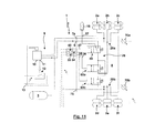
- Fig. 13 a modified embodiment of the Matterachsachsventiliser 72 compared to the embodiment according to Fig. 12 , in that instead of the four 2/2-way valves, only two 4/2-way valves are used, without necessarily having to result in a fundamentally changed functionality.
Abstract
Description
Die Erfindung betrifft eine Niveauregelventileinheit für eine Luftfederungsanlage eines Nutzfahrzeugs, insbesondere eines Zugfahrzeugs und/oder eines Anhängers, sowie eine Luftfederungsanlage mit einer derartigen Niveauregelventileinheit.The invention relates to a level control valve unit for an air suspension system of a commercial vehicle, in particular a towing vehicle and / or a trailer, as well as an air suspension system with such a level control valve unit.
Gemäß
Aus der nicht vorveröffentlichten Patentanmeldung
Der Erfindung liegt die Aufgabe zugrunde, eine verbesserte kompakte Niveauregelventileinheit sowie eine Luftfederungsanlage mit einer kompakten Niveauregelventileinheit vorzuschlagen.The invention has for its object to propose an improved compact level control valve unit and an air suspension system with a compact level control valve unit.
Die Aufgabe der Erfindung wird erfindungsgemäß mit einer Niveauregelventileinheit mit den Merkmalen des unabhängigen Patentanspruchs 1 gelöst. Weitere Ausgestaltungen einer erfindungsgemäßen Niveauregelventileinheit ergeben sich entsprechend den abhängigen Patentansprüchen 2 bis 14. Eine weitere Lösung der der Erfindung zugrunde liegenden Aufgabe ist gegeben durch eine Luftfederungsanlage mit den Merkmalen des nebengeordneten Patentanspruchs 15. Weitere Ausgestaltungen einer derartigen Luftfederungsanlage sind durch die Merkmale der abhängigen Patentansprüche 16 und 17 gekennzeichnet.The object of the invention is achieved with a level control valve unit having the features of
Die erfindungsgemäße Niveauregelventileinheit findet Einsatz für eine Luftfederungsanlage eines Nutzfahrzeugs, insbesondere eines Zugfahrzeugs und/oder eines Anhängers. Die Niveauregelventileinheit besitzt (mindestens) einen Versorgungsanschluss. Der Versorgungsanschluss dient hierbei der Zufuhr von Druckluft aus einer Druckluftquelle, insbesondere einem Vorratsbehälter, was durch unmittelbare Verbindung des Versorgungsanschlusses mit der Druckluftquelle oder durch mittelbare Verbindung, insbesondere über eine Hebe-Senk-Ventileinheit, erfolgen kann.The level control valve unit according to the invention finds application for an air suspension system of a commercial vehicle, in particular a towing vehicle and / or a trailer. The level control valve unit has (at least) one supply port. The supply connection serves to supply compressed air from a compressed air source, in particular a storage container, which can be done by direct connection of the supply connection to the compressed air source or by indirect connection, in particular via a lifting-lowering valve unit.
Die erfindungsgemäße Niveauregelventileinheit besitzt mindestens einen elektrischen Anschluss, über welchen mindestens ein Steuersignal übertragen werden kann. Das Steuersignal wird in der Niveauregelventileinheit verwendet für eine rein elektrisch gesteuerte Niveauregelung (also keine mechanisch gesteuerte Niveauregelung), so dass je nach einem elektrischen Steuersignal die Niveauregelventileinheit ein Niveau der von der Niveauregelventileinheit angesteuerten Luftfederbälge anheben oder absenken oder dieses konstant halten kann. Im Rahmen der vorliegenden Erfindung kann ein beliebiger Anschluss eingesetzt werden, sofern dieser geeignet ist, das genannte elektrische Steuersignal zu übertragen. Hierbei kann es sich um eine einzige Leitung handeln, mit welcher auch unterschiedliche Steuersignale übertragbar sind, ein biaxiales Kabel, einen Anschluss an ein CAN oder anderweitiges Bussystem, um nur einige Beispiele zu nennen. Ebenfalls denkbar ist, dass über den elektrischen Anschluss nicht nur das Steuersignal für die rein elektrische Niveauregelung, sondern auch anderweitige Steuersignale oder ein Versorgungssignal zur elektrischen Leistungsversorgung übertragen wird.The level control valve unit according to the invention has at least one electrical connection, via which at least one control signal can be transmitted. The control signal is used in the level control valve unit for a purely electrically controlled level control (so no mechanically controlled level control), so that depending on an electrical control signal, the level control valve unit can raise or lower a level of air bellows controlled by the level control valve unit or keep this constant. In the context of the present invention, an arbitrary connection can be used, provided that it is suitable for transmitting the said electrical control signal. This can be a single line, with which also different control signals are transferable, a biaxial cable, a connection to a CAN or other bus system, just to name a few examples. It is also conceivable that not only the control signal for the purely electrical level control, but also other control signals or a supply signal to the electrical power supply is transmitted via the electrical connection.
Um die rein elektrische Niveauregelung entsprechend dem zuvor erläuterten elektrischen Steuersignal zu ermöglichen, verfügt die erfindungsgemäße Niveauregelventileinheit über mindestens ein elektrisch angesteuertes oder vorgesteuertes Ventil. Hierbei kann über einen Elektromagneten unmittelbar eine Umschaltung mindestens eines Ventils erfolgen (direkte elektrische Ansteuerung). Ebenfalls möglich ist, dass ein elektromagnetisches Vorsteuerventil Einsatz findet, in welchem mit unter Umständen kleinen Ventilquerschnitten und kleinen elektromagnetisch herbeiführbaren Umschaltkräften ein Vorsteuerdruck beeinflusst wird, welcher dann auf einen pneumatischen Steueranschluss eines so vorgesteuerten Ventils mit unter Umständen größeren Ventilquerschnitten einwirkt (elektrische Vorsteuerung).In order to enable the purely electrical level control according to the above-described electrical control signal, the level control valve unit according to the invention has at least one electrically controlled or pilot operated valve. This can be done via an electromagnet directly switching at least one valve (direct electrical control). It is also possible that an electromagnetic pilot valve is used, in which with possibly small valve cross sections and small electromagnetically caused Umschaltkräften a pilot pressure is influenced, which then acts on a pneumatic control port of such a pilot-controlled valve with possibly larger valve cross-sections (electrical pilot control).
Während gemäß dem Stand der Technik Niveauregelventileinheiten für einkreisige Luftfederungsanlagen lediglich über einen Anschluss für sämtliche Luftfederbälge oder für eine zweikreisige Luftfederungsanlage über zwei Anschlüsse für Luftfederbälge der beiden Kreise verfügt haben, ist in die erfindungsgemäße Niveauregelventileinheit ein Verteiler integriert. Mit dem integrierten Verteiler sind pneumatische Anschlüsse zu Luftfederbälgen verbunden, so dass zwischen der Niveauregelventileinheit und den Luftfederbälgen vorzugsweise lediglich Punkt-Zu-Punkt-Leitungen bestehen können. Hierdurch ergibt sich eine kompakte Niveauregelventileinheit, welche insbesondere das Erfordernis von der Niveauregelventileinheit nachgeordneten T-Verteilern beseitigt, wodurch sich der Bauaufwand und der Montageaufwand verringert und eine Gefahr einer Leckage angesichts der reduzierten Zahl der Verbindungs- oder Verzweigungsstellen verringert.While according to the prior art level control valve units for single-circuit air suspension systems have only one connection for all air spring bellows or for a two-circuit air suspension system via two connections for air bellows of the two circuits, a distributor is integrated in the level control valve unit according to the invention. With the integrated distributor pneumatic connections are connected to air bellows, so that between the level control valve unit and the bellows preferably only point-to-point lines can exist. This results in a compact level control valve unit, which eliminates in particular the requirement of the level control valve unit downstream T-distributors, which reduces the construction cost and installation effort and reduces the risk of leakage in view of the reduced number of connection or branch points.
Möglich ist, dass die Luftfederungsanlage, in welcher die erfindungsgemäße Niveauregelventileinheit Einsatz findet, einkreisig ausgebildet ist. In diesem Fall kann ein integrierter Verteiler Einsatz finden, der mit mehreren pneumatischen Anschlüssen verbunden ist, die jeweils mit einem Luftfederbalg einer Achse und Fahrzeugseite pneumatisch verbunden sind. Demgemäß besitzt der Verteiler von einer Zentralleitung abzweigende Stichleitungen in einer Zahl, welche der Zahl der Luftfederbälge entspricht. In bevorzugter Ausgestaltung kann die Niveauregelventileinheit auch Einsatz finden für eine zweikreisige Luftfederungsanlage. In diesem Fall ist auch unter Umständen die Niveauregelventileinheit zweikreisig ausgebildet. Diese besitzt dann zwei Verteiler, wobei jeweils ein Verteiler mit den Anschlüssen von Luftfederbälgen eines Kreises verbunden ist. Alternativ möglich ist, dass mit einem Anschluss des Verteilers mehrere Luftfederbälge desselben Kreises verbunden sind.It is possible that the air suspension system, in which the level control valve unit according to the invention is used, is designed in a single-circuit. In this case, an integrated distributor can be used, which is connected to a plurality of pneumatic connections, which are each pneumatically connected to an air spring bellows an axle and vehicle side. Accordingly, the distributor has stubs branching from a central line in a number corresponding to the number of the bellows. In a preferred embodiment, the level control valve unit also find application for a two-circuit air suspension system. In this case, under certain circumstances, the level control valve unit is designed with two circuits. This then has two distributors, each one distributor is connected to the connections of Luftfederbälgen a circle. Alternatively, it is possible that with one connection of the distributor several bellows of the same circle are connected.
Möglich ist auch, dass die Niveauregelventileinheit über zwei Versorgungsanschlüsse verfügt, die jeweils mit einem Verteiler und den Luftfederbälgen eines zugeordneten Kreises verbindbar sind. Hierbei können die genannten Versorgungsanschlüsse unmittelbar mit der Druckluftquelle oder unter Zwischenschaltung einer Hebe-Senk-Ventileinheit mit der Druckluftquelle verbunden sein. Möglich ist natürlich auch, dass zusätzlich zu den genannten zwei Versorgungsanschlüssen noch ein weiterer Versorgungsanschluss vorgesehen ist, der (unter Umständen unter Umgehung einer Hebe-Senk-Ventileinheit) mit der Druckluftquelle verbunden ist, so dass alternativ eine Versorgung über die Hebe-Senk-Ventileinheit einerseits und unmittelbar von der Druckluftquelle andererseits möglich ist.It is also possible that the level control valve unit has two supply connections, which are each connectable to a distributor and the bellows of an associated circuit. In this case, said supply connections can be connected directly to the compressed air source or with the interposition of a lifting-lowering valve unit with the compressed air source. It is also possible, of course, that in addition to the two supply connections mentioned, another supply connection is provided which is connected to the compressed air source (possibly bypassing a raising / lowering valve unit), so that alternatively a supply via the raising / lowering valve unit on the one hand and directly from the compressed air source on the other hand is possible.
Als Niveauregelventil in der Niveauregelventileinheit kann hinsichtlich der Ansteuerung und der Bauweise, beispielsweise als Sitzventil oder Schieberventil, jede an sich bekannte Ausgestaltung eines Ventils Einsatz finden. Hierbei kann lediglich ein Ventil als Niveauregelventil Einsatz finden oder eine Mehrzahl von Ventilen, wobei auch die Zahl der von dem Ventil geschalteten Wege und die Zahl der Schaltstellungen der Ventile beliebig ist.As a level control valve in the level control valve unit can be used with regard to the control and the design, for example, as a seat valve or spool valve, any known per se configuration of a valve. Here, only a valve can be used as a level control valve or a plurality of valves, wherein the number of paths connected by the valve and the number of switching positions of the valves is arbitrary.
Für eine besondere Ausgestaltung der Erfindung ist ein Niveauregelventil in Ausgestaltung als 4/3-Wegeventil eingesetzt. Dieses besitzt zwei Anschlüsse, die jeweils über eine Verteiler mit Luftfederbälgen eines Kreises verbunden sind. Weiterhin ist ein Anschluss des Niveauregelventils mit einer Entlüftung verbunden und ein Anschluss mit einem Versorgungsanschluss verbunden. In einer Schaltstellung, beispielsweise einer mittigen Schaltstellung, sind die beiden Anschlüsse, die jeweils über einen Verteiler mit Luftfederbälgen eines Kreises verbunden sind, über eine Drossel miteinander verbunden, so dass die beiden Kreise über die Drossel miteinander gekoppelt sind. Dies hat zur Folge, dass infolge der Drosselwirkung kurzzeitig Druckunterschiede in den einzelnen Kreisen bestehen können, aber nach einer durch die Dimensionierung der Drossel vorgegebenen Zeitspanne Druckunterschiede über die Drossel ausgeglichen werden können. In einer anderen Schaltstellung des 4/3-Wegeventils sind die beiden Anschlüsse, die jeweils über einen Verteiler mit Luftfederbälgen eines Kreises verbunden sind, mit der Entlüftung verbunden. Eine derartige Schaltstellung wird automatisiert, insbesondere durch Ansteuerung durch eine Steuereinheit, angesteuert, wenn ein Konstanthalten des Niveaus des Fahrzeugsaufbaus durch die Niveauregelventileinheit erfordert, dass eine Entlüftung der Luftfederbälge erfolgt. Hierzu kann beispielsweise ein Wegsensor das oder ein Niveau des Fahrzeugaufbaus oder eines Kreises erfassen und das erfasste Niveau in Form eines elektrischen Signals an die genannte Steuereinheit übermitteln, die dann nach Auswertung und Vergleich mit einem Sollniveau oder einer Sollniveau-Spanne eine Herbeiführung der genannten Schaltstellung bewirkt. Zusätzlich ist erfindungsgemäß dann eine weitere Schaltstellung vorgesehen, in welcher die beiden Anschlüsse, die jeweils über einen Verteiler mit Luftfederbälgen eines Kreises verbunden sind, mit einem Versorgungsanschluss verbunden sind. In dieser Schaltstellung kann ein Belüften der Luftfederbälge erfolgen, wenn mittels der Niveauregelventileinheit ein Anheben des Niveaus herbeigeführt werden soll. Sofern der Niveauregelventileinheit ein manuell betätigbares Hebe-Senk-Ventil vorgeordnet ist, kann auch für ein Erkennen, dass eine manuelle Betätigung des Hebe-Senk-Ventils erfolgt, das Niveauregelventil durch geeignete Ansteuerung durch eine Steuereinheit in die letztgenannte Schaltstellung überführt werden. In diesem Fall werden die beiden Anschlüsse, die jeweils über einen Verteiler mit Luftfederbälgen eines Kreises verbunden sind, über das Hebe-Senk-Ventil mit der Druckluftquelle verbunden, so dass das Niveauregelventil lediglich die manuell an dem Hebe-Senk-Ventil angewählten manuellen Zustände an die Luftfederbälge "weitergibt", also eine Belüftung oder eine Entlüftung durch das Hebe-Senk-Ventil erfolgen kann.For a particular embodiment of the invention, a level control valve in design is used as a 4/3-way valve. This has two connections, which are each connected via a distributor with bellows of a circle. Furthermore, a connection of the level control valve is connected to a vent and a connection is connected to a supply connection. In a switching position, for example, a central switching position, the two terminals, which are each connected via a manifold with bellows of a circle, connected to each other via a throttle, so that the two circuits are coupled together via the throttle. As a result, as a result of the throttling effect, there may be brief pressure differences in the individual circuits, but pressure differences across the throttle can be compensated for after a period of time predetermined by the dimensioning of the throttle. In another switching position of the 4/3-way valve are the two terminals, which are each connected via a manifold with bellows of a circle, connected to the vent. Such a switching position is controlled automatically, in particular by activation by a control unit, when a constant maintenance of the level of the vehicle body by the level control valve unit requires that the air bellows are vented. For this purpose, for example, a displacement sensor detect the or a level of the vehicle body or a circle and transmit the detected level in the form of an electrical signal to the said control unit, which then causes after evaluation and comparison with a desired level or a desired level span inducing said switching position , In addition, according to the invention, a further switching position is then provided, in which the two connections, which are each connected via a distributor with air bellows of a circle, are connected to a supply connection. In this switching position, a ventilation of the air spring bellows can take place when raising the level by means of the level control valve unit is to be brought about. If the level control valve unit is preceded by a manually operable lifting-lowering valve, the level control valve can also be converted to the last-mentioned switching position by a suitable control by a control unit for detecting that a manual actuation of the lifting-lowering valve takes place. In this case, the two ports, which are each connected via a manifold with bellows of a circle, connected via the lifting-lowering valve to the compressed air source, so that the level control valve only manually selected on the lifting-lowering valve manual states the air spring bellows "weiterergibt", so ventilation or venting can be done by the lifting-lowering valve.
In bevorzugter Ausgestaltung besitzt die Niveauregelventileinheit eine Schaltstellung, in welcher ein Versorgungsanschluss über den Verteiler mit Anschlüssen von Luftfederbälgen verbunden ist. Eine derartige Schaltstellung kann alternativ oder kumulativ für vielfältige unterschiedliche Zwecke genutzt werden:
- Möglich ist, dass in dieser Schaltstellung Druckluft von dem Versorgungsanschluss über den Verteiler zu den Luftfederbälgen gelangt, so dass im Rahmen der elektronischen Niveauregelung diese Schaltstellung eingenommen wird, um das Niveau des Fahrzeugaufbaus zu heben. Hierzu kann der Versorgungsanschluss unmittelbar mit der Druckluftquelle oder mittelbar unter Zwischenschaltung weiterer pneumatischer Baueinheiten mit der Druckluftquelle verbunden sein.
- Ebenfalls möglich ist, dass diese Schaltstellung eingenommen wird, um die Niveauregelventileinheit in eine Art Durchlassstellung zu schalten, in welcher die pneumatische Beaufschlagung der Luftfederbälge nicht durch die Niveauregelventileinheit erfolgt, sondern über eine zusätzliche Baueinheit erfolgt, die der Niveauregelventileinheit, nämlich dem Versorgungsanschluss, vorgeordnet ist. Beispielsweise kann diese Schaltstellung eingenommen werden, wenn dem Versorgungsanschluss ein Hebe-Senk-Ventil vorgeordnet ist und ein elektrisches Signal vorliegt, welches indiziert, dass eine manuelle Betätigung des Hebe-Senk-Ventils erfolgt, aufgrund dieses Signals die Niveauregelventileinheit, beispielsweise durch eine Steuereinheit, in die genannte Schaltstellung umgeschaltet wird und dann über das Hebe-Senk-Ventil durch die Niveauregelventileinheit in ihrer "Durchlassstellung" die manuelle verursachte Be- und Entlüftung erfolgen soll. Für diese Ausführungsform ist es möglich, dass das Hebe-Senk-Ventil neben der Be- und Entlüftungsstellung auch eine zusätzliche Sperrstellung besitzt, in welcher trotz Niveauregelventileinheit in der genannten Durchlassstellung das Niveau der Luftfederbälge gehalten wird. Im Extremfall möglich wäre auch, dass die Hebe-Senk-Ventileinheit an sich nur eine Be- und eine Entlüftungsstellung besitzt, die manuell anwählbar sind zum Heben und Senken des Fahrzeugaufbaus. Wird hingegen erkannt, dass ein Niveau konstant gehalten werden soll, was durch manuelle Vorgabe eines entsprechenden Wunsches erfolgen kann und/oder durch automatisiertes Erkennen einer minimalen oder maximalen Niveauhöhe, kann bei Hebe-Senk-Ventil in Be- oder Entlüftungsstellung die Niveauregelventileinheit von der Durchlassstellung in die Sperrstellung geschaltet werden. In diesem Fall kann das Absperren der Luftfederbälge nicht durch die Hebe-Senk-Ventileinheit, sondern durch die Niveauregelventileinheit erfolgen, so dass die Hebe-Senk-Ventileinheit auch ohne Sperrstellung ausgebildet sein kann. Hinsichtlich näherer Details wird auf die am selben Tag wie die vorliegende Anmeldung eingereichte Anmeldung der Anmelderin mit dem Titel "Luftfederungsanlage" verwiesen.
- It is possible that in this switching position compressed air passes from the supply connection via the distributor to the air spring bellows, so that in the context of the electronic level control this switching position is taken to raise the level of the vehicle body. For this purpose, the supply connection can be connected directly to the compressed air source or indirectly with the interposition of further pneumatic units with the compressed air source.
- It is also possible that this switching position is taken to switch the level control valve unit in a kind of passage position in which the pneumatic loading of the bellows is not carried out by the level control valve unit, but via an additional structural unit, which is the level control valve unit, namely the supply port upstream , For example, this switching position can be taken when the supply port upstream of a lift-lower valve and an electrical signal is present, which indicates that a manual actuation of the raise-lower valve takes place, due to this signal, the level control valve unit, for example by a control unit, is switched to the above switching position and then on the lifting-lowering valve by the level control valve unit in their "passage position" the manual caused ventilation should take place. For this embodiment, it is possible that the lifting-lowering valve in addition to the ventilation position also has an additional locking position, in which despite level control valve unit in the said passage position, the level of the air spring bellows is maintained. In extreme cases, it would also be possible for the lifting / lowering valve unit to have only one loading and one venting position, which can be manually selected for raising and lowering the vehicle body. If, on the other hand, it is recognized that a level is to be kept constant, which can be done by manually specifying a corresponding request and / or by automatically recognizing a minimum or maximum level height, the level control valve unit can move from the passage position to the lowering / lowering valve in the ventilation position be switched into the blocking position. In this case, the shut-off of the bellows can not be done by the raising-lowering valve unit, but by the level control valve unit, so that the lifting-lowering valve unit can be formed without blocking position. For further details, reference is made to the applicant's application entitled "Air Suspension System" filed on the same day as the present application.
Um lediglich eine weitere Möglichkeit der vielen unterschiedlichen Möglichkeiten für die Ausgestaltung des Niveauregelventils zu nennen, kann das Niveauregelventil als 3/2-Wegeventil ausgebildet sein. In diesem Fall verfügt das Niveauregelventil über einen Anschluss, der über mindestens einen Verteiler mit Luftfederbälgen verbunden ist. Ein weiterer Anschluss des Niveauregelventils ist mit einem Versorgungsanschluss verbunden. Schließlich ist der dritte Anschluss mit einer Entlüftung verbunden. In einer Schaltstellung ist der mit den Luftfederbälgen verbundene Anschluss mit dem Versorgungsanschluss verbunden, so dass unmittelbar ein Heben des Niveaus erfolgt und/oder eine Verbindung zu einem manuell betätigbaren Hebe-Senk-Ventil geschaffen ist. In einer anderen Schaltstellung ist der mit den Luftfederbälgen verbundene Anschluss mit der Entlüftung verbunden, um eine Verringerung des Niveaus herbeizuführen.To name just another possibility of the many different possibilities for the design of the level control valve, the level control valve can be designed as a 3/2-way valve. In this case, the level control valve has a connection, which is connected via at least one distributor with air bellows. Another connection of the level control valve is connected to a supply connection. Finally, the third port is connected to a vent. In a switching position, the connection connected to the air bellows is connected to the supply connection, so that immediately the level is raised and / or a connection is made to a manually operated lift / lower valve. In another switch position, the port connected to the air bellows is connected to the vent to bring about a reduction in the level.
Insbesondere für den Fall, dass das Niveauregelventil mit einfachen pneumatischen Komponenten ausgebildet sein soll, kann dieses mit einem 3/2-Wegeventil und einem vor- oder nachgeordneten 2/2-Wegeventil ausgebildet sein. Beispielsweise kann das 3/2-Wegeventil eine Be- und eine Entlüftungsstellung besitzen, so dass für nachgeschaltetes 2/2-Wegeventil in Durchlassstellung über das 3/2-Wegeventil eine Be- und Entlüftung der Luftfederbälge ansteuerbar ist. Wird hingegen das 2/2-Wegeventil in seine Sperrstellung überführt, sind die Luftfederbälge unabhängig von der Stellung des 3/2-Wegeventils von der Entlüftung und dem Versorgungsanschluss abgesperrt.In particular, in the event that the level control valve should be designed with simple pneumatic components, this may be formed with a 3/2-way valve and a pre- or downstream 2/2-way valve. For example, the 3/2-way valve have a loading and a venting position, so that for downstream 2/2-way valve in passage position via the 3/2-way valve, a ventilation of the bellows is controlled. If, however, the 2/2-way valve is transferred to its blocking position, the air bellows are shut off regardless of the position of the 3/2-way valve of the vent and the supply connection.
Für den Fall, dass die erfindungsgemäße Niveauregelventileinheit Einsatz finden soll in einer zweikreisigen Luftfederungsanlage, kann auch eine Kombination aus einem 3/2-Wegeventil und zwei 2/2-Wegeventilen Einsatz finden, wobei in diesem Fall die 2/2-Wegeventile jeweils über einen Verteiler mit Luftfederbälgen eines Kreises verbunden sind. Demgemäß kann für jeden Kreis separat eine Be- oder Entlüftung erfolgen je nach Schaltstellung des 3/2-Wegeventils einerseits und der zwei 2/2-Wegeventile andererseits.In the event that the level control valve unit according to the invention should be used in a two-circuit air suspension system, a combination of a 3/2-way valve and two 2/2-way valves can be used, in which case the 2/2-way valves each have a Manifolds are connected to air bellows of a circle. Accordingly, it can be done separately for each circuit a ventilation or venting depending on the switching position of the 3/2-way valve on the one hand and the two 2/2-way valves on the other.
Um eine noch kompaktere Bauweise auch für den Fall zu erzielen, dass das Fahrzeug mit einer Liftachse ausgestattet werden soll, kann in die Niveauregelventileinheit auch ein Liftachsventil integriert sein. Diese Integration kann in ein gemeinsames Gehäuse als fester Bestandteil desselben erfolgen. Ebenfalls möglich ist, dass die Niveauregelventileinheit modular ausgebildet ist, wobei ein Teilmodul mit dem Liftachsventil gebildet ist. Dieses kann beispielsweise an ein Hauptmodul der Niveauregelventileinheit angeflanscht werden, wobei mit dem Anflanschen vorzugsweise auch pneumatische und/oder elektrische Verbindungen geschaffen werden für eine Kombination eines Hauptmoduls der Niveauregelventileinheit mit dem Niveauregelventil mit dem Teilmodul für das Liftachsventil. Für eine derartige Ausgestaltung kann beispielsweise das Liftachsventil über einen Versorgungsanschluss des Hauptmoduls der Niveauregelventileinheit mit Druckluft versorgt werden und/oder eine Entlüftung des Hauptmoduls auch für das Liftachsventil genutzt werden. Entsprechend kann ein elektrisches Signal, welches in dem Hauptmodul verwendet wird, auch zu dem Modul für das Liftachsventil "durchgeschleift" sein oder über entsprechende Steckverbindungen übergeben werden.In order to achieve an even more compact construction even in the event that the vehicle is to be equipped with a lift axle, a lift axle valve can also be integrated into the level control valve unit. This integration can be done in a common housing as an integral part of the same. It is also possible that the level control valve unit is modular, wherein a partial module is formed with the Liftachsventil. This can be flanged, for example, to a main module of the level control valve unit, with the flange preferably also pneumatic and / or electrical connections are created for a combination of a main module of the level control valve unit with the level control valve with the submodule for the Liftachsventil. For such a configuration, for example, the lift axle valve can be supplied with compressed air via a supply connection of the main module of the level control valve unit and / or a venting of the main module can also be used for the lift axle valve. Accordingly, an electrical signal, which in the Main module is used, also "looped" to the module for the Liftachsventil or be passed over appropriate connectors.
Auch für das Liftachsventil kann ein Ventil beliebiger Ansteuerung, Bauart, mit beliebigen Schaltstellungen und beliebiger Zahl der Anschlüsse Einsatz finden. Um diesbezüglich lediglich ein mögliches Beispiel zu nennen kann für das Liftachsventil ein 6/2-Wegeventil eingesetzt werden. Dieses besitzt dann einen Anschluss, der mit einem Luftfederbalg, sämtlichen Luftfederbälgen oder Luftfederbälgen eines Kreises oder einem zugeordneten Verteiler verbunden ist. Des Weiteren besitzt das Liftachsventil einen Anschluss, der mit einem Liftbalg verbunden ist. Ein weiterer Anschluss des Liftachsventils ist mit einem Tragbalg verbunden. In einer ersten Schaltstellung, in welcher die Liftachse nicht aktiv ist, ist über das Liftachsventil der Liftbalg mit einem Versorgungsanschluss verbunden, so dass dieser mit Druckluft beaufschlagt wird und die Liftachse angehoben wird. In dieser Schaltstellung wird im Gegenzug ein Tragbalg (oder werden mehrere Tragbälge der Liftachse) mit einer Entlüftung verbunden, was für die angehobene Liftachse erforderlich ist. Der mit einem Luftfederbalg verbundene Anschluss des Liftachsventils ist in dieser Schaltstellung gesperrt, so dass das Druckluftniveau der Luftfederbälge für andere Achsen als die Liftachse durch das Liftachsventil nicht beeinflusst wird. Das Liftachsventil besitzt darüber hinaus eine weitere Schaltstellung, in welcher der Liftbalg mit der Entlüftung verbunden ist, was für das Absenken der Liftachse erforderlich ist. In dieser Schaltstellung sollen die Tragbälge der Liftachse druckbeaufschlagt werden, um einen Teil der Last mittels der Liftachse zu tragen. In dieser Schaltstellung wird allerdings der Tragbalg nicht unmittelbar mit der Druckluftquelle verbunden. Vielmehr wird über das Liftachsventil in dieser Schaltstellung mindestens ein Tragbalg, vorzugsweise werden sämtliche Tragbälge der Liftachse, mit mindestens einem Luftfederbalg verbunden, beispielsweise Luftfederbälgen eines Kreises oder sämtlichen Luftfederbälgen. Dies hat zur Folge, dass in sämtlichen miteinander verbundenen Luftfederbälgen und Tragbälgen derselbe Druck über das Liftachsventil herbeigeführt wird, so dass sich die Last gleichmäßig oder gemäß einer vorgegebenen Achsverteilung auf die Liftachse und die weiteren Achsen verteilen kann.Also for the Liftachsventil a valve of any type of control, design, with any switch positions and any number of connections can be used. To name just one possible example in this regard, a 6/2-way valve can be used for the Liftachsventil. This then has a connection which is connected to an air spring bellows, all Luftfederbälgen or air spring bellows of a circle or an associated distributor. Furthermore, the lift axle valve has a connection which is connected to a lift bellows. Another connection of the lift axle valve is connected to a bellows. In a first shift position, in which the lift axle is not active, the lift bellows is connected to a supply connection via the lift axle valve, so that it is acted upon by compressed air and the lift axle is raised. In this switching position in return a bellows (or more Tragbälge the lift axle) are connected to a vent, which is required for the raised lift axle. The connected to an air bag connection of the lift axle valve is locked in this switching position, so that the compressed air level of the bellows for other axes than the lift axle is not affected by the Liftachsventil. The Liftachsventil also has a further switching position in which the lift bellows is connected to the vent, which is required for lowering the lift axle. In this switching position, the supporting bellows of the lifting axle should be pressurized in order to carry part of the load by means of the lifting axle. In this switching position, however, the bellows is not directly connected to the compressed air source. Rather, at least one bellows, preferably all Tragbälge the lift axle, connected to at least one air spring bellows, for example, air spring bellows of a circle or all Luftfederbälgen on the Liftachsventil in this switch position. As a result, the same pressure is brought about via the lifting axle valve in all interconnected bellows and bellows, so that the load can be distributed evenly or according to a predetermined axle distribution on the lift axle and the other axles.
In weiterer Ausgestaltung der Erfindung wird die Niveauregelventileinheit multifunktional auch für die Ansteuerung einer Überschussachse verwendet. Unter einer derartigen Überschussachse wird eine Achse verstanden, welche bei einer Beladung des Fahrzeugs unterhalb eines vorgegebenen oder auch flexiblen Schwellwerts keine Achslast trägt, aber mit Überschreitung des Schwellwerts für die Beladung einen Teil der Achslast übernimmt, wobei vorzugsweise dann eine gleichmäßige oder vorgegebene Verteilung der Achslasten auf die Überschussachse und die weiteren Achsen erfolgt. Erfindungsgemäß ist dann eine Überschussachsventileinheit in die Niveauregelventileinheit integriert. Diese kann beispielsweise mit geeigneter elektrischer Ansteuerung durch eine Steuereinheit bei Überschreitung des Schwellwerts der Beladung, was beispielsweise mittels eines Drucksensors an den Luftfederbälgen der ständig belasteten Achsen erkannt werden kann, eine pneumatische Verbindung zwischen den Luftfederbälgen der Überschussachse einerseits und den weiteren Luftfederbälgen schaffen, so dass ein pneumatischer Druckausgleich erfolgt mit einer Aufteilung der Achslasten auf die einzelnen Luftfederbälge. Durch die Gestaltung der pneumatischen Leitungsquerschnitte, Drosseln u. ä kann das Zeitverhalten für den pneumatischen Ausgleich beeinflusst werden und ggf. auch eine Achslastverteilung vorgegeben werden. Für die Ausgestaltung der Überschussachsventileinheit mit unterschiedlichen Überschussachsventilen gibt es vielfältige Möglichkeiten. Lediglich beispielhaft führt die folgende Beschreibung Beispiele mit Ausbildung der Überschussachsventileinheit mit einem 5/3-Wegeventil, einem 3/3-Wegeventil und mehreren Überschussachsventilen, insbesondere in Ausgestaltung als 2/2-Wegeventile oder als 4/2-Wegeventile, an.In a further embodiment of the invention, the level control valve unit is used multifunctional for the control of an excess axis. Such an excess axle is understood to mean an axle which does not bear an axle load when the vehicle is loaded below a predetermined or also flexible threshold value, but takes over part of the axle load when the load threshold value is exceeded, wherein preferably then a uniform or predetermined distribution of the axle loads on the excess axis and the other axes takes place. According to the invention, a surplus axle valve unit is then integrated into the level control valve unit. This can, for example, with suitable electrical control by a control unit when exceeding the threshold value of the load, which can be detected for example by means of a pressure sensor on the bellows of constantly loaded axles, create a pneumatic connection between the bellows of the excess axis on the one hand and the other air bellows, so that A pneumatic pressure compensation takes place with a distribution of the axle loads on the individual bellows. Due to the design of the pneumatic line cross-sections, throttles u. ä the time behavior for the pneumatic compensation can be influenced and, if necessary, also an axle load distribution can be specified. For the design of the excess axle valve unit with different excess axial valves there are many possibilities. For example only, the following description gives examples with the design of the Überachsachsventileinheit with a 5/3-way valve, a 3/3-way valve and a plurality of excess axial valves, in particular in the form of 2/2-way valves or 4/2-way valves on.
Für eine weitere erfindungsgemäße Lösung ist in einer Luftfederungsanlage eine Niveauregelventileinheit eingesetzt, wobei die Niveauregelventileinheit wie zuvor erläutert ausgebildet sein kann. Zwischen eine Druckluftquelle und mindestens einen Versorgungsanschluss der Niveauregelventileinheit kann dann eine manuell betätigbare Hebe-Senk-Ventileinheit zwischengeschaltet sein.For a further inventive solution, a level control valve unit is used in an air suspension system, wherein the level control valve unit may be formed as previously explained. Between a compressed air source and at least one supply connection of the level control valve unit, a manually operable lifting-lowering valve unit can then be interposed.
In weiterer Ausgestaltung kann die Hebe-Senk-Ventileinheit zwei Anschlüsse besitzen, die jeweils mit einem Versorgungsanschluss der Niveauregelventileinheit verbunden sind. Dies ist insbesondere von Vorteil, wenn die Luftfederungsanlage zweikreisig ausgebildet ist und über die Hebe-Senk-Ventileinheit auch die beiden Luftfederkreise unabhängig voneinander be- und entlüftet werden.In a further embodiment, the lifting-lowering valve unit may have two connections which are each connected to a supply connection of the level control valve unit. This is particularly advantageous if the air suspension system is designed to be double-circuited and the two air spring circuits are also ventilated and vented independently of one another via the lifting-lowering valve unit.
In weiterer Ausgestaltung der Erfindung ist die Hebe-Senk-Ventileinheit mit einem Druckschalter pneumatisch gekoppelt, der in Abhängigkeit einer manuell vorgegebenen Betriebsstellung der Hebe-Senk-Ventileinheit ein elektrisches Signal erzeugt. Hierbei kann der Druckschalter in der Niveauregelventileinheit angeordnet sein, also in diese integriert sein. Der Druckschalter kann aber auch an die Niveauregelventileinheit angeflanscht sein. Möglich ist allerdings auch, dass der Druckschalter außerhalb der Niveauregelventileinheit an beliebiger Stelle oder im Bereich einer Steuereinheit angeordnet sein. Das elektrische Ausgangssignal wird dann einer Steuereinheit zugeführt. Die Steuereinheit ist mit einer Steuerungslogik oder einem Programm ausgestattet, mittels dessen eine Ansteuerung der Niveauregelventileinheit erfolgt. Die Steuerungslogik ist hierbei derart ausgestaltet, dass die Ansteuerung der Niveauregelventileinheit in Abhängigkeit des von dem Druckschalter erzeugten elektrischen Signals erfolgt. So kann beispielsweise bei manueller Betätigung der Hebe-Senk-Ventileinheit der Druckschalter das Signal erzeugen, welches der Steuereinheit indiziert, dass die manuelle Betätigung erfolgt. In diesem Fall kann die Niveauregelventileinheit in ihre Durchlassstellung geschaltet werden, wie dies bereits zuvor erläutert worden ist, um eine Beeinflussung der pneumatischen Verhältnisse in den Luftfederbälgen durch die Hebe-Senk-Ventileinheit zu ermöglichen.In a further embodiment of the invention, the lifting-lowering valve unit is pneumatically coupled to a pressure switch which generates an electrical signal in response to a manually predetermined operating position of the lifting-lowering valve unit. In this case, the pressure switch can be arranged in the level control valve unit, ie integrated into it. The pressure switch can also be flanged to the level control valve unit. However, it is also possible that the pressure switch outside of the level control valve unit at any point or in the Be arranged area of a control unit. The electrical output signal is then supplied to a control unit. The control unit is equipped with a control logic or a program, by means of which a control of the level control valve unit takes place. The control logic is in this case designed such that the control of the level control valve unit takes place as a function of the electrical signal generated by the pressure switch. For example, upon manual actuation of the raising / lowering valve unit, the pressure switch may generate the signal indicating that the control unit is being manually operated. In this case, the level control valve unit can be switched to its passage position, as has already been explained above, to allow influencing of the pneumatic conditions in the air spring bellows by the lifting-lowering valve unit.
Vorteilhafte Weiterbildungen der Erfindung ergeben sich aus den Patentansprüchen, der Beschreibung und den Zeichnungen. Die in der Beschreibungseinleitung genannten Vorteile von Merkmalen und von Kombinationen mehrerer Merkmale sind lediglich beispielhaft und können alternativ oder kumulativ zur Wirkung kommen, ohne dass die Vorteile zwingend von erfindungsgemäßen Ausführungsformen erzielt werden müssen. Weitere Merkmale sind den Zeichnungen - insbesondere den dargestellten Geometrien und den relativen Abmessungen mehrerer Bauteile zueinander sowie deren relativer Anordnung und Wirkverbindung - zu entnehmen. Die Kombination von Merkmalen unterschiedlicher Ausführungsformen der Erfindung oder von Merkmalen unterschiedlicher Patentansprüche ist ebenfalls abweichend von den gewählten Rückbeziehungen der Patentansprüche möglich und wird hiermit angeregt. Dies betrifft auch solche Merkmale, die in separaten Zeichnungen dargestellt sind oder bei deren Beschreibung genannt werden. Diese Merkmale können auch mit Merkmalen unterschiedlicher Patentansprüche kombiniert werden. Ebenso können in den Patentansprüchen aufgeführte Merkmale für weitere Ausführungsformen der Erfindung entfallen.Advantageous developments of the invention will become apparent from the claims, the description and the drawings. The advantages of features and of combinations of several features mentioned in the introduction to the description are merely exemplary and can come into effect alternatively or cumulatively, without the advantages having to be achieved by embodiments according to the invention. Further features are the drawings - in particular the illustrated geometries and the relative dimensions of several components to each other and their relative arrangement and operative connection - refer. The combination of features of different embodiments of the invention or of features of different claims is also possible deviating from the chosen relationships of the claims and is hereby stimulated. This also applies to those features which are shown in separate drawings or are mentioned in their description. These features can also be combined with features of different claims. Likewise, in the claims listed features for further embodiments of the invention can be omitted.
Im Folgenden wird die Erfindung anhand in den Figuren dargestellter bevorzugter Ausführungsbeispiele weiter erläutert und beschrieben.
- Fig. 1
- zeigt in schematischer Darstellung eine einkreisige Luftfederungsanlage mit Hebe-Senk-Ventileinheit und nachgeschalteter elektrisch angesteuerter Niveauregelventileinheit.
- Fig. 2
- zeigt in schematischer Darstellung eine zweikreisige Luftfederungsanlage mit Hebe-Senk-Ventileinheit und nachgeschalteter elektrisch angesteuerter Niveauregelventileinheit.
- Fig. 3
- zeigt in schematischer Darstellung eine zweikreisige Luftfederungsanlage gemäß
Fig. 2 , wobei hier allerdings die beiden Kreise über eine in die Niveauregeventileinheit integrierte Drossel miteinander gekoppelt sind. - Fig. 4
- zeigt eine zweikreisige Luftfederungsanlage mit Einsatz elektromagnetischer Vorsteuerventile, detaillierterer schematischer Darstellung der Niveauregelventileinheit und einer integrierten Liftachsventileinheit.
- Fig. 5
- zeigt eine zweikreisige Luftfederungsanlage grundsätzlich gemäß
Fig. 4 , bei welcher allerdings die Niveauregelventileinheit modular mit einem Niveauregelmodul und einem Liftachsmodul gebildet ist. - Fig. 6
- zeigt schematisch eine einkreisige Luftfederungsanlage mit einer Niveauregelventileinheit, in welche ein Liftachsventil integriert ist.
- Fig. 7
- zeigt schematisch eine Luftfederungsanlage mit einer Überschussachse, wobei hier in die Niveauregelventileinheit eine Überschussachsventileinheit integriert ist und zwei Kreise der Luftfederungsanlage über eine integrierte Drossel miteinander verbunden sind.
- Fig. 8
- zeigt schematisch eine Luftfederungsanlage mit Überschussachse, wobei zwei Kreise der Luftfederungsanlage gegeneinander absperrbar sind.
- Fig. 9
- zeigt schematisch eine Luftfederungsanlage mit Überschussachse, wobei in die Niveauregelventileinheit eine Überschussachsventileinheit integriert ist und die Luftfederungsanlage einkreisig ausgebildet ist.
- Fig. 10
- zeigt schematisch eine Luftfederungsanlage mit einer elektrisch vorgesteuerten Niveauregelventileinheit, in welcher zwei Luftfederkreise über ein gemeinsames 3/2-Wegeventil und jeweils
ein 2/2-Wegeventil mit Druckluft beaufschlagt werden. - Fig. 11
- zeigt eine Luftfederungsanlage mit einer grundsätzlich der Niveauregelventileinheit gemäß
Fig. 10 entsprechenden Niveauregelventileinheit, wobei hier allerdings zwischen Vorratsbehälter und Niveauregelventileinheit eine Hebe-Senk-Ventileinheit zwischengeschaltet ist. - Fig. 12
- zeigt schematisch eine Luftfederungsanlage mit Hebe-Senk-Ventileinheit und elektrisch vorgesteuerter Niveauregelventileinheit, in welcher zwei über eine Drossel miteinander gekoppelte Luftfederkreise über ein gemeinsames 3/2-Wegeventil und jeweils
ein 2/2-Wegeventil mit Druckluft beaufschlagt werden und eine Überschussachsventileinheit zur separaten Ansteuerung von Luftfederbälgen auf unterschiedlichen Seiten einer Überschussachse in die Niveauregelventileinheit integriert ist. - Fig. 13
- zeigt schematisch eine Luftfederungsanlage entsprechend
Fig. 12 mit alternativer Ausgestaltung einer Überschussachsventileinheit.
- Fig. 1
- shows a schematic representation of a single-circuit air suspension system with lifting-lowering valve unit and downstream electrically controlled level control valve unit.
- Fig. 2
- shows a schematic representation of a two-circuit air suspension system with lifting-lowering valve unit and downstream electrically controlled level control valve unit.
- Fig. 3
- shows a schematic representation of a two-circuit air suspension system according to
Fig. 2 , in which case, however, the two circuits are coupled together via a throttle integrated in the level control valve unit. - Fig. 4
- shows a dual-circuit air suspension system with the use of electromagnetic pilot valves, more detailed schematic representation of the level control valve unit and an integrated Liftachsventileinheit.
- Fig. 5
- shows a dual-circuit air suspension system basically according
Fig. 4 in which, however, the level control valve unit is modular with a level control module and a Liftachsmodul formed. - Fig. 6
- shows schematically a single-circuit air suspension system with a level control valve unit, in which a Liftachsventil is integrated.
- Fig. 7
- schematically shows an air suspension system with an excess axis, in which case a Überachsachsventileinheit is integrated into the level control valve unit and two circuits of the air suspension system are connected to each other via an integrated throttle.
- Fig. 8
- schematically shows an air suspension system with excess axis, wherein two circles of the air suspension system against each other can be shut off.
- Fig. 9
- schematically shows an air suspension system with excess axis, wherein in the level control valve unit, a Überachsachsventileinheit is integrated and the air suspension system is formed in a single circle.
- Fig. 10
- schematically shows an air suspension system with an electrically piloted level control valve unit in which two air spring circuits are acted upon by a common 3/2-way valve and a respective 2/2-way valve with compressed air.
- Fig. 11
- shows an air suspension system with a basically the level control valve unit according to
Fig. 10 corresponding level control valve unit, but here between reservoir and level control valve unit, a lifting-lowering valve unit is interposed. - Fig. 12
- schematically shows an air suspension system with lifting-lowering valve unit and electrically pilot-operated level control valve unit in which two coupled via a throttle air spring circuits via a common 3/2-way valve and a 2/2-way valve are acted upon with compressed air and a Überachsachsventileinheit for separate control is integrated by air spring bellows on different sides of an excess axis in the level control valve unit.
- Fig. 13
- schematically shows an air suspension system accordingly
Fig. 12 with an alternative embodiment of a Überachsachsventileinheit.
In der Luftfederungsanlage 1 ist ein Vorratsbehälter 3 über parallele Leitungszweige 4, 5 jeweils mit einem Versorgungsanschluss 6, 7 einer Niveauregelventileinheit 8 verbunden. Der Leitungszweig 4 verbindet unmittelbar den Vorratsbehälter 3 mit dem Versorgungsanschluss 6, während in dem Leitungszweig 5 die Verbindung des Vorratsbehälters 3 mit dem Versorgungsanschluss 7 über eine Hebe-Senk-Ventileinheit 9 erfolgt. In dem Fachmann an sich bekannter Weise kann die Hebe-Senk-Ventileinheit 9 manuell von einer Stellung Stopp in eine Stellung Fahrt und/oder Senken überführt werden, wobei in der Stellung Stopp der Leitungszweig 5 abgesperrt ist, in der Stellung Heben eine pneumatische Verbindung zwischen dem Vorratsbehälter 3 und dem Versorgungsanschluss 7 geschaffen ist und in der Stellung Senken der Versorgungsanschluss 7 mit einer Entlüftung 10 der Hebe-Senk-Ventileinheit 9 verbunden ist. Möglich ist, dass die Stellung Stopp ohne manuelle Betätigung automatisiert eingenommen ist, insbesondere durch Einsatz einer sogenannten Totmann-Feder.In the
Die Hebe-Senk-Ventileinheit 9 besitzt einen Auslass 11, der mit einem Druckschalter 12 pneumatisch verbunden ist. Für eine manuelle Betätigung der Hebe-Senk-Ventileinheit 9 wird der Druckschalter 12 betätigt, insbesondere geschlossen, so dass der Druckschalter 12 ein elektrisches Ausgangssignal 13 erzeugt, welches von der manuellen Betätigung der Hebe-Senk-Ventileinheit 9 abhängig ist. Beispielsweise kann der Druckschalter 12 in der Stellung Heben und Senken geschlossen sein, während dieser sich in einer Öffnungsstellung befindet, wenn die Hebe-Senk-Ventileinheit 9 in der Stellung Stopp ist.The lifting-lowering
Für das in
Neben den Versorgungsanschlüssen 6, 7 besitzt die Niveauregelventileinheit 8 pneumatische Anschlüsse 15a-15f, die jeweils als Punkt-Zu-Punkt-Verbindung, also ohne Verzweigung, mit den Luftfederbälgen 2a bis 2f pneumatisch verbunden sind. Darüber hinaus besitzt die Niveauregelventileinheit 8 eine in
In der Niveauregelventileinheit 8 ist der Versorgungsanschluss 7 unmittelbar pneumatisch gekoppelt mit den Anschlüssen 15a-15f. Dies erfolgt von einer Zentralleitung 19 über einen Verteiler 20, der hier mit zwei Teil-Verteilern 20a, 20b gebildet ist, die mit der Zentralleitung 19 gekoppelt sind und jeweils drei Stichleitungen 21a-21f besitzen, die die Zentralleitung 19 mit den Anschlüssen 15a-15f verbinden. Somit kann je nach Stellung der Hebe-Senk-Ventileinheit 9 in der Stellung Heben, Senken oder Stopp über den Versorgungsanschluss 7 eine Belüftung, Entlüftung sämtlicher Luftfederbälge 2a-2f erfolgen oder der pneumatische Austausch von Druckluft in der Stellung Stopp über den Versorgungsanschluss 7 abgesperrt werden. In die Zentralleitung 19 mündet darüber hinaus eine Niveauregelleitung 22. Für aktivierte Niveauregelung, insbesondere im Fahrbetrieb, befindet sich die Hebe-Senk-Ventileinheit 9 in der Stellung Stopp oder wird diese automatisiert in die Stellung Stopp bzw. eine Stellung Fahrt überführt, so dass der Versorgungsanschluss 7 abgesperrt ist. Über in
In den Figuren ebenfalls dargestellt ist ein Wegsensor 70 in beliebiger Ausgestaltung, welcher das Niveau des Fahrzeugaufbaus oder eines einzelnen Luftfederbalgs 2 oder einer Gruppe von Luftfederbälgen erfasst und welcher ein elektrisches Ausgangssignal erzeugt, das dann der Steuereinheit zur geeigneten elektrischen Ansteuerung der Anschlüsse 17, 18 zugeführt wird. Um lediglich einige Möglichkeiten für die Ausbildung des Wegsensors von der Vielzahl unterschiedlicher Möglichkeiten zu benennen, kann ein Wegsensor auf Grundlage eines HallSensors, eine Infrarot-Abstandsmessung oder Sensoren, wie diese in
Für das in
In die Niveauregelventileinheit 8 integriert ist ein Niveauregelventil 28, welches hier als 4/3-Wegeventil 29 ausgebildet ist. Das 4/3-Wegeventil 29 besitzt Anschlüsse 30a, 30b. Der Anschluss 30a ist über die Niveauregelleitung 22a mit dem Verteiler 20a, also den Anschlüssen 15a, 15b und Luftfederbälgen 2a, 2b sowie dem Versorgungsanschluss 7a, verbunden, während der Anschluss 30b über die Niveauregelleitung 22b mit dem Verteiler 20b, also den Anschlüssen 15d, 15e und den Luftfederbälgen 2d und 2e sowie dem Versorgungsanschluss 7b, verbunden ist. Ein weiterer Anschluss 31 ist mit der Entlüftung 16 pneumatisch verbunden, während ein Anschluss 32 mit dem Versorgungsanschluss 6, also über den Leitungszweig 4 mit dem Vorratsbehälter 3, pneumatisch verbunden ist. Die elektrischen Anschlüsse 17, 18 der Niveauregelventileinheit 8 sind elektropneumatischen Vorsteuerventilen 33, 34 zugeordnet, welche einen Vorsteuerdruck in Steuerleitungen 35, 36 vorgeben. Ohne (oder bei gleicher) pneumatischer Beaufschlagung der Steuerleitungen 35, 36 befindet sich das 4/3-Wegeventil 29 in der in
Optional kann zusätzlich zu dem Niveauregelventil 28 in der Niveauregelventileinheit 8 ein Liftachsventil 39 Einsatz finden. Für das in
In der in
Das in
Die in
Für das Ausführungsbeispiel der Luftfederungsanlage 1 gemäß
Auch die Überschussachsventileinheit 72 ist elektrisch angesteuert, hier mit elektropneumatischer Vorsteuerung. Über elektrische Anschlüsse 79, 80 werden von der Steuereinheit elektropneumatische Vorsteuerventile 81, 82 angesteuert, welche die Steuerdrücke in Steuerleitungen 83, 84 vorgeben. Für drucklose Steuerleitungen 83, 84 befindet sich infolge der Federn in der Überschussachsventileinheit 72 diese in der in
Für das Ausführungsbeispiel gemäß
Die Luftfederungsanlage 1 gemäß
- Ohne pneumatische Beaufschlagung der Steuerleitungen 35, 36, 47 befindet sich die Luftfederungsanlage in dem in
Fig. 10 skizzierten Betriebszustand, in dem über die 2/2-Wegeventile Luftfederbälge 2a-2f abgesperrt sind, so dass das Druckniveau indiesen Luftfederbälgen 2a-2f konstant gehalten wird. - Durch selektive, alternative oder kumulative Druckluftbeaufschlagung der Steuerleitungen 35, 36 über elektrische Bestromung der Anschlüsse 18, 25 kann eines oder können beide 2/2-
Wegeventile Durchlassstellung geschalteten 2/2-Wegeventil zugeordnete Kreis - Mit pneumatischer Druckbeaufschlagung der Steuerleitung 47
kann das 3/2-Wegeventil 59 in seine Belüftungsstellung umgeschaltet werden, für welcheein 2/2-Wegeventil Kreis
- Without pneumatic loading of the
control lines Fig. 10 sketched operating state in which the air spring bellows 2a-2f are shut off via the 2/2-way valves - By selectively, alternatively or cumulatively applying compressed air to the
control lines connections way valves control line 47 is in the forward position without pressure being applied switched 2/2-way valve associatedcircuit - With pneumatic pressurization of the
control line 47, the 3/2-way valve 59 can be switched to its ventilation position, for which causes a 2/2-way valve circuit
Bei dem Ausführungsbeispiel der Luftfederungsanlage 1 gemäß
Das Ausführungsbeispiel der Luftfederungsanlage 1 gemäß
Gemäß
Für das in
- 11
- LuftfederungsanlageAir suspension system
- 22
- Luftfederbalgsuspension bellows
- 33
- Vorratsbehälterreservoir
- 44
- Leitungszweigleg
- 55
- Leitungszweigleg
- 66
- Versorgungsanschlusssupply terminal
- 77
- Versorgungsanschlusssupply terminal
- 88th
- NiveauregelventileinheitLevel control valve unit
- 99
- Hebe-Senk-VentileinheitRaise-valve unit
- 1010
- Entlüftungvent
- 1111
- Auslassoutlet
- 1212
- Druckschalterpressure switch
- 1313
- Ausgangssignaloutput
- 1414
- Baueinheitunit
- 1515
- Anschlussconnection
- 1616
- Entlüftungvent
- 1717
- elektr. Steueranschlusselec. control connection
- 1818
- elektr. Steueranschlusselec. control connection
- 1919
- ZentralleitungCentral line
- 2020
- Verteilerdistributor
- 2121
- Stichleitungstub
- 2222
- NiveauregelleitungLevel control line
- 2323
- Kreiscircle
- 2424
- Kreiscircle
- 2525
- elektr. Steueranschlusselec. control connection
- 2626
- Tragbalgbellows
- 2727
- Liftbalglift bag
- 2828
- NiveauregelventilLevel control valve
- 2929
- 4/3-Wegeventil4/3-way valve
- 3030
- Anschlussconnection
- 3131
- Anschlussconnection
- 3232
- Anschlussconnection
- 3333
- Vorsteuerventilpilot valve
- 3434
- Vorsteuerventilpilot valve
- 3535
- Steuerleitungcontrol line
- 3636
- Steuerleitungcontrol line
- 3737
- Federfeather
- 3838
- Drosselthrottle
- 3939
- LiftachsventilLifting axle
- 4040
- 6/2-Wegeventil6/2 directional valve
- 4141
- Anschlussconnection
- 4242
- Anschlussconnection
- 4343
- Anschlussconnection
- 4444
- Anschlussconnection
- 4545
- Anschlussconnection
- 4646
- Federfeather
- 4747
- Steuerleitungcontrol line
- 4848
- Vorsteuerventilpilot valve
- 4949
- Anschlussconnection
- 5050
- Anschlussconnection
- 5151
- NiveauregelmodulLevel control module
- 5252
- LiftachsmodulLiftachsmodul
- 5353
- Schnittstelleinterface
- 5454
- Leitungsverbindungline connection
- 5555
- Leitungsverbindungline connection
- 5656
- Leitungsverbindungline connection
- 5757
- Anschlussconnection
- 5858
- 3/3-Wegeventil3/3-way valve
- 5959
- 3/2-Wegeventil3/2-way valve
- 6060
- 2/2-Wegeventil2/2 way valve
- 6161
- Anschlussconnection
- 6262
- Anschlussconnection
- 6363
- Anschlussconnection
- 6464
- Verzweigungbranch
- 6565
- Anschlussconnection
- 6666
- Anschlussconnection
- 6767
- Federfeather
- 6868
- Federfeather
- 6969
- Federfeather
- 7070
- Wegsensordisplacement sensor
- 7171
- Drosselthrottle
- 7272
- ÜberschussachsventileinheitAbout Schu Sachs valve unit
- 7373
- Luftfederbalgsuspension bellows
- 7474
- Drucksensorpressure sensor
- 7575
- 5/3-Wegeventil5/3-way valve
- 7676
- Anschlussconnection
- 7777
- Anschlussconnection
- 7878
- Anschlussconnection
- 7979
- Anschlussconnection
- 8080
- Anschlussconnection
- 8181
- Vorsteuerventilpilot valve
- 8282
- Vorsteuerventilpilot valve
- 8383
- Steuerleitungcontrol line
- 8484
- Steuerleitungcontrol line
- 8585
- 3/3-Wegeventil3/3-way valve
- 8686
- Drosselthrottle
- 8787
- ÜberschussachsventilAbout Schu Sachs valve
- 8888
- ÜberschussachsventilAbout Schu Sachs valve
- 8989
- Anschlussconnection
- 9090
- Anschlussconnection
- 9191
- Anschlussconnection
- 9292
- Anschlussconnection
- 9393
- Entlüftungvent
- 9494
- Vorsteuerventilpilot valve
- 9595
- Vorsteuerventilpilot valve
- 9696
- Vorsteuerventilpilot valve
- 9797
- ÜberschussachsventilAbout Schu Sachs valve
- 9898
- ÜberschussachsventilAbout Schu Sachs valve
Claims (17)
Applications Claiming Priority (1)
| Application Number | Priority Date | Filing Date | Title |
|---|---|---|---|
| DE102011051505.4A DE102011051505C5 (en) | 2011-07-01 | 2011-07-01 | Level control valve unit with integrated distributor |
Publications (1)
| Publication Number | Publication Date |
|---|---|
| EP2540536A1 true EP2540536A1 (en) | 2013-01-02 |
Family
ID=46318972
Family Applications (1)
| Application Number | Title | Priority Date | Filing Date |
|---|---|---|---|
| EP12172209A Withdrawn EP2540536A1 (en) | 2011-07-01 | 2012-06-15 | Level regulation valve unit |
Country Status (2)
| Country | Link |
|---|---|
| EP (1) | EP2540536A1 (en) |
| DE (1) | DE102011051505C5 (en) |
Cited By (4)
| Publication number | Priority date | Publication date | Assignee | Title |
|---|---|---|---|---|
| CN104044427A (en) * | 2014-07-07 | 2014-09-17 | 中国重汽集团济南动力有限公司 | Three-axle passenger car lifting bridge control system |
| EP2957442A1 (en) * | 2014-06-18 | 2015-12-23 | KNORR-BREMSE Systeme für Nutzfahrzeuge GmbH | Pneumatic suspension unit for lifting and lowering a vehicle structure |
| EP2957441A1 (en) * | 2014-06-18 | 2015-12-23 | KNORR-BREMSE Systeme für Nutzfahrzeuge GmbH | Pneumatic suspension unit for lifting and lowering a vehicle structure |
| EP3705322A1 (en) * | 2019-03-07 | 2020-09-09 | WABCO GmbH | Method for controlling the height of a pneumatic vehicle and device therefor |
Families Citing this family (1)
| Publication number | Priority date | Publication date | Assignee | Title |
|---|---|---|---|---|
| DE102021133412A1 (en) * | 2021-12-16 | 2023-06-22 | Zf Cv Systems Europe Bv | Valve arrangement and method for controlling a liftable trailing axle of a trailer vehicle |
Citations (13)
| Publication number | Priority date | Publication date | Assignee | Title |
|---|---|---|---|---|
| EP0170794A2 (en) * | 1984-08-04 | 1986-02-12 | WABCO Westinghouse Fahrzeugbremsen GmbH | Air spring device for vehicles |
| DE3915826C1 (en) * | 1989-05-16 | 1990-06-28 | Graubremse Gmbh, 6900 Heidelberg, De | |
| DE4003746A1 (en) * | 1990-02-08 | 1991-08-14 | Wabco Westinghouse Fahrzeug | Loading measuring device for vehicle pneumatic suspension system - uses variation in measured spacing between measuring point and defined ref. level for determining vehicle weight |
| EP0520147A1 (en) * | 1991-06-24 | 1992-12-30 | Grau Gmbh | Control system for lifting or lowering the body of vehicles with pneumatic suspension |
| DE19530260A1 (en) * | 1995-08-17 | 1997-02-20 | Grau Gmbh | Air suspension system for vehicles |
| DE19944873C1 (en) * | 1999-09-18 | 2001-01-04 | Haldex Brake Prod Gmbh | Control unit for lifting and lowering vehicle structures of air-sprung vehicles has between compressed air source and air spring bellows two parallel branch pipes with locking valve |
| WO2001089863A2 (en) | 2000-05-25 | 2001-11-29 | Holland Neway International, Inc. | Height control system and sensor therefor |
| DE102005017590B3 (en) * | 2005-04-16 | 2006-06-14 | Haldex Brake Products Gmbh | Change-over valve for e.g. trailer, has controllable position providing connection between input-sided connection and output-sided connections, and transverse throttles arranged in respective output-sided piping portions |
| DE102007008159A1 (en) * | 2007-02-19 | 2008-08-21 | Knorr-Bremse Systeme für Nutzfahrzeuge GmbH | Air suspension device with electrically operated shut-off valve |
| WO2010089088A2 (en) * | 2009-02-05 | 2010-08-12 | Knorr-Bremse Systeme für Nutzfahrzeuge GmbH | Leveling valve having one connection each for air-spring bellows on the right and left side |
| EP2125398B1 (en) | 2007-02-19 | 2010-09-01 | KNORR-BREMSE Systeme für Nutzfahrzeuge GmbH | Pneumatic suspension unit comprising control valves that are exclusively actuated by a pressure-medium |
| EP2059423B1 (en) | 2006-08-31 | 2010-10-06 | WABCO GmbH | Pneumatic module |
| WO2011076304A1 (en) * | 2009-12-23 | 2011-06-30 | Wabco Gmbh | Valve device for an air suspension system |
Family Cites Families (2)
| Publication number | Priority date | Publication date | Assignee | Title |
|---|---|---|---|---|
| DE102006032348A1 (en) | 2006-07-13 | 2008-01-17 | Bpw Bergische Achsen Kg | Valve arrangement i.e. dual-circuit valve arrangement, for air spring of vehicle i.e. trailer vehicle, has two-way valve with connections that are provided at side of air springs, where valve is arranged between manifold valve and springs |
| DE102010003463B4 (en) * | 2010-03-30 | 2013-11-14 | Haldex Brake Products Gmbh | Pneumatic units for air suspension systems |
-
2011
- 2011-07-01 DE DE102011051505.4A patent/DE102011051505C5/en active Active
-
2012
- 2012-06-15 EP EP12172209A patent/EP2540536A1/en not_active Withdrawn
Patent Citations (13)
| Publication number | Priority date | Publication date | Assignee | Title |
|---|---|---|---|---|
| EP0170794A2 (en) * | 1984-08-04 | 1986-02-12 | WABCO Westinghouse Fahrzeugbremsen GmbH | Air spring device for vehicles |
| DE3915826C1 (en) * | 1989-05-16 | 1990-06-28 | Graubremse Gmbh, 6900 Heidelberg, De | |
| DE4003746A1 (en) * | 1990-02-08 | 1991-08-14 | Wabco Westinghouse Fahrzeug | Loading measuring device for vehicle pneumatic suspension system - uses variation in measured spacing between measuring point and defined ref. level for determining vehicle weight |
| EP0520147A1 (en) * | 1991-06-24 | 1992-12-30 | Grau Gmbh | Control system for lifting or lowering the body of vehicles with pneumatic suspension |
| DE19530260A1 (en) * | 1995-08-17 | 1997-02-20 | Grau Gmbh | Air suspension system for vehicles |
| DE19944873C1 (en) * | 1999-09-18 | 2001-01-04 | Haldex Brake Prod Gmbh | Control unit for lifting and lowering vehicle structures of air-sprung vehicles has between compressed air source and air spring bellows two parallel branch pipes with locking valve |
| WO2001089863A2 (en) | 2000-05-25 | 2001-11-29 | Holland Neway International, Inc. | Height control system and sensor therefor |
| DE102005017590B3 (en) * | 2005-04-16 | 2006-06-14 | Haldex Brake Products Gmbh | Change-over valve for e.g. trailer, has controllable position providing connection between input-sided connection and output-sided connections, and transverse throttles arranged in respective output-sided piping portions |
| EP2059423B1 (en) | 2006-08-31 | 2010-10-06 | WABCO GmbH | Pneumatic module |
| DE102007008159A1 (en) * | 2007-02-19 | 2008-08-21 | Knorr-Bremse Systeme für Nutzfahrzeuge GmbH | Air suspension device with electrically operated shut-off valve |
| EP2125398B1 (en) | 2007-02-19 | 2010-09-01 | KNORR-BREMSE Systeme für Nutzfahrzeuge GmbH | Pneumatic suspension unit comprising control valves that are exclusively actuated by a pressure-medium |
| WO2010089088A2 (en) * | 2009-02-05 | 2010-08-12 | Knorr-Bremse Systeme für Nutzfahrzeuge GmbH | Leveling valve having one connection each for air-spring bellows on the right and left side |
| WO2011076304A1 (en) * | 2009-12-23 | 2011-06-30 | Wabco Gmbh | Valve device for an air suspension system |
Cited By (5)
| Publication number | Priority date | Publication date | Assignee | Title |
|---|---|---|---|---|
| EP2957442A1 (en) * | 2014-06-18 | 2015-12-23 | KNORR-BREMSE Systeme für Nutzfahrzeuge GmbH | Pneumatic suspension unit for lifting and lowering a vehicle structure |
| EP2957441A1 (en) * | 2014-06-18 | 2015-12-23 | KNORR-BREMSE Systeme für Nutzfahrzeuge GmbH | Pneumatic suspension unit for lifting and lowering a vehicle structure |
| CN104044427A (en) * | 2014-07-07 | 2014-09-17 | 中国重汽集团济南动力有限公司 | Three-axle passenger car lifting bridge control system |
| CN104044427B (en) * | 2014-07-07 | 2016-03-02 | 中国重汽集团济南动力有限公司 | Triple-axle coach lift bridge control system |
| EP3705322A1 (en) * | 2019-03-07 | 2020-09-09 | WABCO GmbH | Method for controlling the height of a pneumatic vehicle and device therefor |
Also Published As
| Publication number | Publication date |
|---|---|
| DE102011051505B4 (en) | 2015-12-31 |
| DE102011051505A1 (en) | 2013-01-03 |
| DE102011051505C5 (en) | 2023-09-07 |
Similar Documents
| Publication | Publication Date | Title |
|---|---|---|
| EP3600991B1 (en) | Electro pneumatic hand brake with integrated tcv (scandinavian activation) | |
| DE10333610B4 (en) | Compressed air treatment device for motor vehicle compressed air systems | |
| EP3600981B1 (en) | Electropneumatic hand brake (eph) having integrated tcv (european and scandinavian control) | |
| EP2615003B2 (en) | Parking brake module for a pressure-driven brake system of a vehicle suitable for coupling a trailer, brake system and vehicle equipped with the parking brake module and method for same | |
| EP2757006B1 (en) | Valve device for a compressed air system of a trailer of a commercial vehicle | |
| EP4061678B1 (en) | Brake system with safer emergency stop function and method for same | |
| DE102017005980A1 (en) | Integrated trailer control module (TCV) with external electropneumatic manual brake unit (EPH) | |
| EP4058334B1 (en) | Electro-pneumatic control module | |
| DE102011051505B4 (en) | Level control valve unit with integrated distributor | |
| DE102007008156A1 (en) | Air suspension device with exclusively pressure-medium-operated control valves | |
| DE19918070B4 (en) | Pressure control device for electro-pneumatic brake systems of vehicles, in particular commercial vehicles | |
| EP4069559A1 (en) | Monostable and fault-tolerant parking brake valve assembly | |
| EP2540538B1 (en) | Pneumatic spring assembly | |
| EP3749558B1 (en) | Braking system for a utility vehicle, compressed air processing unit, and use of a compressed air processing unit | |
| DE102013100538A1 (en) | Compressed air system of a trailer of a commercial vehicle | |
| DE102015115082B4 (en) | Valve unit for pneumatic applications as well as air suspension system | |
| WO2020015975A1 (en) | Electropneumatic parking brake module with directly controlled valves and anti-compound connection | |
| EP3112231A1 (en) | Parking brake module, brake system and vehicle using same and method for operating a parking brake having such a module | |
| DE102009055210B4 (en) | Compressed air system | |
| EP2957441B1 (en) | Pneumatic suspension unit for lifting and lowering a vehicle structure | |
| EP3892504B1 (en) | Trailer control module of a brake system operated by means of pressure fluid of a tractor with a valve arrangement for controlling a pneumatic brake system of a trailer vehicle | |
| EP2572909A2 (en) | Valve device for a pneumatic suspension unit of a vehicle |
Legal Events
| Date | Code | Title | Description |
|---|---|---|---|
| PUAI | Public reference made under article 153(3) epc to a published international application that has entered the european phase |
Free format text: ORIGINAL CODE: 0009012 |
|
| AK | Designated contracting states |
Kind code of ref document: A1 Designated state(s): AL AT BE BG CH CY CZ DE DK EE ES FI FR GB GR HR HU IE IS IT LI LT LU LV MC MK MT NL NO PL PT RO RS SE SI SK SM TR |
|
| AX | Request for extension of the european patent |
Extension state: BA ME |
|
| RIN1 | Information on inventor provided before grant (corrected) |
Inventor name: TSCHOEKE, TOBIAS Inventor name: NOECKER, JOACHIM Inventor name: BECKE, STEFAN Inventor name: SULZYC, GEORG |
|
| 17P | Request for examination filed |
Effective date: 20130531 |
|
| RBV | Designated contracting states (corrected) |
Designated state(s): AL AT BE BG CH CY CZ DE DK EE ES FI FR GB GR HR HU IE IS IT LI LT LU LV MC MK MT NL NO PL PT RO RS SE SI SK SM TR |
|
| 17Q | First examination report despatched |
Effective date: 20150911 |
|
| STAA | Information on the status of an ep patent application or granted ep patent |
Free format text: STATUS: THE APPLICATION IS DEEMED TO BE WITHDRAWN |
|
| 18D | Application deemed to be withdrawn |
Effective date: 20160729 |