EP2540466A1 - Prepreg lamination head and prepreg automatic lamination device equipped with same - Google Patents
Prepreg lamination head and prepreg automatic lamination device equipped with same Download PDFInfo
- Publication number
- EP2540466A1 EP2540466A1 EP11747451A EP11747451A EP2540466A1 EP 2540466 A1 EP2540466 A1 EP 2540466A1 EP 11747451 A EP11747451 A EP 11747451A EP 11747451 A EP11747451 A EP 11747451A EP 2540466 A1 EP2540466 A1 EP 2540466A1
- Authority
- EP
- European Patent Office
- Prior art keywords
- prepreg
- roller
- paper liner
- prepreg sheet
- lamination
- Prior art date
- Legal status (The legal status is an assumption and is not a legal conclusion. Google has not performed a legal analysis and makes no representation as to the accuracy of the status listed.)
- Granted
Links
Images


Classifications
-
- B—PERFORMING OPERATIONS; TRANSPORTING
- B29—WORKING OF PLASTICS; WORKING OF SUBSTANCES IN A PLASTIC STATE IN GENERAL
- B29C—SHAPING OR JOINING OF PLASTICS; SHAPING OF MATERIAL IN A PLASTIC STATE, NOT OTHERWISE PROVIDED FOR; AFTER-TREATMENT OF THE SHAPED PRODUCTS, e.g. REPAIRING
- B29C70/00—Shaping composites, i.e. plastics material comprising reinforcements, fillers or preformed parts, e.g. inserts
- B29C70/04—Shaping composites, i.e. plastics material comprising reinforcements, fillers or preformed parts, e.g. inserts comprising reinforcements only, e.g. self-reinforcing plastics
- B29C70/28—Shaping operations therefor
- B29C70/30—Shaping by lay-up, i.e. applying fibres, tape or broadsheet on a mould, former or core; Shaping by spray-up, i.e. spraying of fibres on a mould, former or core
- B29C70/38—Automated lay-up, e.g. using robots, laying filaments according to predetermined patterns
- B29C70/386—Automated tape laying [ATL]
- B29C70/388—Tape placement heads, e.g. component parts, details or accessories
-
- B—PERFORMING OPERATIONS; TRANSPORTING
- B29—WORKING OF PLASTICS; WORKING OF SUBSTANCES IN A PLASTIC STATE IN GENERAL
- B29K—INDEXING SCHEME ASSOCIATED WITH SUBCLASSES B29B, B29C OR B29D, RELATING TO MOULDING MATERIALS OR TO MATERIALS FOR MOULDS, REINFORCEMENTS, FILLERS OR PREFORMED PARTS, e.g. INSERTS
- B29K2105/00—Condition, form or state of moulded material or of the material to be shaped
- B29K2105/06—Condition, form or state of moulded material or of the material to be shaped containing reinforcements, fillers or inserts
- B29K2105/08—Condition, form or state of moulded material or of the material to be shaped containing reinforcements, fillers or inserts of continuous length, e.g. cords, rovings, mats, fabrics, strands or yarns
- B29K2105/0872—Prepregs
-
- B—PERFORMING OPERATIONS; TRANSPORTING
- B29—WORKING OF PLASTICS; WORKING OF SUBSTANCES IN A PLASTIC STATE IN GENERAL
- B29K—INDEXING SCHEME ASSOCIATED WITH SUBCLASSES B29B, B29C OR B29D, RELATING TO MOULDING MATERIALS OR TO MATERIALS FOR MOULDS, REINFORCEMENTS, FILLERS OR PREFORMED PARTS, e.g. INSERTS
- B29K2105/00—Condition, form or state of moulded material or of the material to be shaped
- B29K2105/24—Condition, form or state of moulded material or of the material to be shaped crosslinked or vulcanised
- B29K2105/243—Partially cured
-
- Y—GENERAL TAGGING OF NEW TECHNOLOGICAL DEVELOPMENTS; GENERAL TAGGING OF CROSS-SECTIONAL TECHNOLOGIES SPANNING OVER SEVERAL SECTIONS OF THE IPC; TECHNICAL SUBJECTS COVERED BY FORMER USPC CROSS-REFERENCE ART COLLECTIONS [XRACs] AND DIGESTS
- Y10—TECHNICAL SUBJECTS COVERED BY FORMER USPC
- Y10T—TECHNICAL SUBJECTS COVERED BY FORMER US CLASSIFICATION
- Y10T156/00—Adhesive bonding and miscellaneous chemical manufacture
- Y10T156/17—Surface bonding means and/or assemblymeans with work feeding or handling means
- Y10T156/1702—For plural parts or plural areas of single part
- Y10T156/1705—Lamina transferred to base from adhered flexible web or sheet type carrier
- Y10T156/1707—Discrete spaced laminae on adhered carrier
-
- Y—GENERAL TAGGING OF NEW TECHNOLOGICAL DEVELOPMENTS; GENERAL TAGGING OF CROSS-SECTIONAL TECHNOLOGIES SPANNING OVER SEVERAL SECTIONS OF THE IPC; TECHNICAL SUBJECTS COVERED BY FORMER USPC CROSS-REFERENCE ART COLLECTIONS [XRACs] AND DIGESTS
- Y10—TECHNICAL SUBJECTS COVERED BY FORMER USPC
- Y10T—TECHNICAL SUBJECTS COVERED BY FORMER US CLASSIFICATION
- Y10T156/00—Adhesive bonding and miscellaneous chemical manufacture
- Y10T156/17—Surface bonding means and/or assemblymeans with work feeding or handling means
- Y10T156/1702—For plural parts or plural areas of single part
- Y10T156/1705—Lamina transferred to base from adhered flexible web or sheet type carrier
- Y10T156/1707—Discrete spaced laminae on adhered carrier
- Y10T156/171—Means serially presenting discrete base articles or separate portions of a single article
-
- Y—GENERAL TAGGING OF NEW TECHNOLOGICAL DEVELOPMENTS; GENERAL TAGGING OF CROSS-SECTIONAL TECHNOLOGIES SPANNING OVER SEVERAL SECTIONS OF THE IPC; TECHNICAL SUBJECTS COVERED BY FORMER USPC CROSS-REFERENCE ART COLLECTIONS [XRACs] AND DIGESTS
- Y10—TECHNICAL SUBJECTS COVERED BY FORMER USPC
- Y10T—TECHNICAL SUBJECTS COVERED BY FORMER US CLASSIFICATION
- Y10T156/00—Adhesive bonding and miscellaneous chemical manufacture
- Y10T156/17—Surface bonding means and/or assemblymeans with work feeding or handling means
- Y10T156/1702—For plural parts or plural areas of single part
- Y10T156/1712—Indefinite or running length work
- Y10T156/1741—Progressive continuous bonding press [e.g., roll couples]
Definitions
- the present invention relates to a prepreg lamination head for laminating prepreg sheets having a fiber sheet impregnated with resin to form a prepreg laminated body, and a prepreg automatic lamination apparatus having the same.
- a prepreg lamination head for laminating prepreg sheets having a fiber sheet impregnated with resin to form a prepreg laminated body
- a prepreg automatic lamination apparatus having the same.
- FRP sheet multiple prepreg sheets having a fiber sheet impregnated with resin are laminated to manufacture a prepreg laminated body (form a composite material), and this prepreg laminated body is used to manufacture (form) the main wings, a fuselage, a main plane, or the like of an aircraft.
- carbon fibers are frequently used as fibers because the carbon fibers have excellent features, such as light weight, high strength, and high elasticity.
- the prepreg sheet is formed by aligning the fiber directions of multiple fibers. It is formed in a state where the fiber sheet is impregnated in an ultraviolet curable resin or a thermosetting resin as the impregnation resin and in a state where the resin is half-cured (imperfectly cured or uncured). For this reason, a paper liner is stuck to a surface (or both surfaces) of the prepreg sheet.
- the prepreg laminated body is manufactured (formed) by removing the paper liner from the prepreg sheet and integrally laminating the multiple prepreg sheets while making the fiber directions to intersect each other.
- the prepreg laminated body is manufactured by laminating a prepreg sheet (angle layer) in which fiber directions are turned, for example, in the 45 degree direction or in the 90 degree direction on a prepreg sheet whose fiber direction is in 0-degree direction (0-degree layer). Then, on top of the angled layer, a prepreg sheet in the 0 degree direction (0-degree layer) is further laminated. As explained above.
- the prepreg laminated body is manufactured by laminating a pre-determined number of prepreg sheets on a work (a work to be laminated) integrally formed by prepreg sheets having fiber directions in the prepreg sheets intersecting to the fiber direction of the previous layer sequentially
- the prepreg automatic lamination apparatus A includes: a lamination table 2 that is provided on a stand 1 and placed so as to freely advance and retreat in the direction T1; a pair of gate-type supports 3 and 4 enclosing the lamination table 2 therebetween with an interval in the direction T1; a 0-degree layer lamination head 5 (prepreg lamination head) that is supported by the gate-type support 3 and disposed above the lamination table 2; and an angled layer lamination head 6 on the lamination table 2.
- the angled layer lamination head 6 is rotatably supported by the second gate-type support 4 allowing rotation around an axis that extends in a vertical direction.
- the 0-degree layer lamination head 5 includes: a feed roller 9, around which a prepreg sheet 8 with a paper liner 7 attached on one of its surface is reeled; a support roller 10 that supports the prepreg sheet 8 fed from the feed roller 9 by being wrapped around by the prepreg sheet 8; a die cutter 11, which is provided between the feed roller 9 and the support roller 10 and cuts the prepreg sheet 8 alone in a pre-determined length (to fit to the size of a piece of the work to be laminated) without cutting the paper liner 7; a front pressing roller (first roller) 12, which guides in the direction T1 for the prepreg sheet 8 to be laminated on the work placed on the lamination table 2 and applies the prepreg sheet 8 on the work by pressing the prepreg sheet 8 from the surface which had the paper line 7; a rear pressing roller (second roller) 13, which presses again the prepreg sheet 8 that has passed the front pressing roller 12 and peels the paper liner 7 from the prepreg sheet 8; and a paper liner recovery roller 14
- the angled layer lamination head 6 includes: a feed roller 15, around which a prepreg sheet 8 with a paper liner 7 attached on one of its surface is reeled; a support roller16 that supports the prepreg sheet 8 fed from the feed roller 15 by being wrapped around by the prepreg sheet 8; a die cutter 17, which is provided between the feed roller 15 and the support roller 16 and cuts the prepreg sheet 8 alone in a pre-determined length (to fit to the size of a piece of the work to be laminated) without cutting the paper liner 7; a guide roller 18a, which guides the prepreg sheet 8 fed from the support roller 16 to be laminated on the work; a scraper roller (guide roller) 18b, which guides the prepreg sheet 8 to be laminated on the work working together with the guide roller 18a and peels off the paper liner 7 from the prepreg sheet 8; a lamination shoe 19, which is provided between the guide roller 18a and scraper roller 18b, is able to shift its position back and forth, and presses the prepreg
- the paper liner recovery roller 14 is rotated, the paper liner 7 is pulled, and the prepreg sheet 8 is fed from the feed roller 9. Also, during the feeding of the prepreg sheet 8 from the feed roller 9, the prepreg sheet 8 alone is kept being cut by the die cutter 11 in a pre-determined length.
- the prepreg sheet 8 that is cut up in this way is sent so as to run along the top face of the work through the support roller 10, and is pressed against the work from the paper liner 7 side by the front pressing roller 12 (primary transfer pressing).
- the cut piece of the prepreg sheets 8, which are obtained by cutting and dividing the prepreg sheet 8, are applied on the work to be laminated repeatedly and integrally laminated on the work.
- the prepreg sheet 8 applied on the work is pressed again (Secondary transfer pressing), while the paper line 7 is peeled off from the prepreg sheet 8 and rolled up by the paper liner recovery roller 14.
- the prepreg sheet 8 of 0-degree layer the fiber direction of which is along with the length direction of the work (length direction of the prepreg laminated body, the conveying direction of the lamination table 2, the first direction T1), is laminated on the work with the 0-degree layer lamination head 5.
- the work on which the prepreg sheet 8 is laminated by the 0-degree layer lamination head 5 is conveyed toward the angled layer lamination head 6 by the lamination table 2.
- the angled layer lamination head 6 is rotated and, disposed so as to have a predetermined intersection angle of, for example, 45 degrees or 90 degrees with respect to the length direction (the conveying direction of the lamination table 2 or the first direction T1) of the work, and the paper liner recovery roller 20 is rolled in this state. Consequently, the paper liner 7 is pulled, the prepreg sheet 8 is fed from the feed roller 15, and only the prepreg sheet 8 is cut up at every predetermined length by the die cutter 17. At this time, the prepreg sheet 8 is cut up so as to be divided into a shape (for example, a rhomboidal shape when a 45-degree layer is laminated and formed on the work) according to the piece to be laminated of the work.
- a shape for example, a rhomboidal shape when a 45-degree layer is laminated
- the lamination shoe 19 moves in the fiber direction (intersection direction T2) of the prepreg sheet 8 while pressing the prepreg sheet 8.
- a cut piece S1 of the prepreg sheet 8 cut up and divided by the die cutter 17 is applied as a stack on the piece to be laminated of the work W, and is integrally laminated.
- the scraper roller 18b while passing through the scraper roller 18b, only the paper liner 7 is peeled off from the prepreg sheet 8 applied to the work W and reeled around the paper liner recovery roller 20.
- the angle layer prepreg sheet 8 the fiber direction T2 of which intersects the length direction of the work W (which is the fiber direction of T1 of the prepreg sheet 8 in the 0-degree layer), is laminated on the work W with the angled layer lamination head 6.
- the prepreg laminated body is manufactured by sequentially laminating the prepreg sheets 8 by the 0-degree layer lamination head 5 and the angled layer lamination head 6 while making the fiber directions T1 and T2 to intersect each other.
- the prepreg sheet 8 and the paper liner 7 are adhered so tightly.
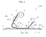
- a cut terminal portion S of the prepreg sheet 8 (cut piece 21) is peeled up and the curling-up occurs as shown in FIG. 3 , when the prepreg sheet 8 having passed the rear pressing roller 13 is laminated on the work W (or lamination table 2 (body to be laminated)) by the 0-degree layer lamination head 5 (prepreg lamination head).
- the subsequent prepreg sheet 8 is laminated on a work W having the prepreg sheet 8 with the curling-up at the cut terminal portion S.
- a prepreg laminated body with a bumpy surface is manufactured (formed), making it difficult to maintain a good product quality.
- the 0-degree layer (prepreg sheet 8) at the cut terminal portion S can be bended due to the applied pressure.
- the carbon fibers are very vulnerable against the shearing force. Therefore, the intended mechanical characteristic could not be obtained if the prepreg sheet 8 was bended, which is another reason for making it difficult to maintain a good product quality.
- the invention has been made in view of the above circumstances and an object thereof is to provide a prepreg lamination head, and a prepreg automatic lamination apparatus equipped with the same, capable of reliably preventing the curling-up at a cut terminal portion of a prepreg sheet to suitably laminate a 0-degree layer prepreg sheet.
- the invention provides the following means.
- the first aspect of the present invention is a prepreg lamination head for laminating a plurality of prepreg sheets made of fiber sheet impregnated with resin to form a prepreg laminated body, wherein a paper liner being stuck over a first side of the prepreg sheet, and a direction of a fiber in the prepreg sheets being directed to a first direction along with a length direction of the laminated body
- the prepreg lamination head including: a first roller, which is provided in a front side of a work being laminated and guides the prepreg sheet to the first direction for the prepreg sheet to be laminated on the work being laminated; a second roller, which is provided in a rear side of the work being laminated and guides the prepreg sheet, which has passed the first roller, for the prepreg sheet to be pressed from the first side of the prepreg sheet and for the paper liner to be peeled off from the first side of the prepreg sheet; and a forward-placed paper liner peeling device, which
- the paper liner can be peeled off between the first roller and the second roller before the paper liner is peeled off by the second roller by providing the forward-placed paper liner peeling device between the first roller and the second roller. Additionally, since the paper liner, which was peeled off by the forward-placed paper liner peeling device, is guided to return to the second roller, and applied to the first side of the prepreg sheet while the prepreg sheet is pressed by the second roller, similarly to the related art, it is possible to press the prepreg sheet by the second roller through the paper liner, and integrally laminate the prepreg sheet on the body to be laminated (work).
- the forward-placed paper liner peeling device may include a third roller, which is provided above the first and second rollers and on which the liner paper between the first and second rollers is hanged over.
- the paper liner can be peeled off from the first side of the prepreg sheet having passed the first roller by providing the third roller between the first roller and the second roller and hanging over the paper liner on the third roller. Additionally, it is possible to guide the paper liner with the third roller so as to return the paper liner to the second roller reliably and easily
- the forward-placed paper liner peeling device which includes the third roller, may include: a scraper, which peels off the paper liner from the first side of the prepreg sheet having passed the first roller and guide the peeled paper liner to the third roller, the scraper being provided between the first and third rollers in the first direction, and below the third roller.
- the paper liner can be more reliably peeled off from the first side of the prepreg sheet having passed the first roller by providing the scraper between the first roller and the second roller below the third roller.
- the second aspect of the present invention is a prepreg automatic lamination apparatus for producing a prepreg laminated body by laminating a plurality of prepreg sheets formed by impregnation of a fiber sheet in resin
- a prepreg automatic lamination apparatus for producing a prepreg laminated body by laminating a plurality of prepreg sheets formed by impregnation of a fiber sheet in resin
- the prepreg lamination head of any one of the first aspect of the present invention described above and a lamination table, which allows a forward and a backward movement of the work being laminated relative to the prepreg lamination head in the first direction
- the lamination table includes: a plurality of suction holes opening at a top surface of the lamination table on which the work to be laminated is placed; and the work to be laminated is maintained in a stuck-state by sucking air from the suction holes.
- any one of the above described prepreg lamination heads is included. Therefore, the curling-up, which occurs at the cut terminal portion of the prepreg sheet (cut piece) having passed the second roller (rear pressing roller) when the paper liner is peeled off from the work to be laminated as in the conventional auto laminating apparatus, can be prevented. Additionally, the lamination table is formed so as to include the plurality of suction holes, and air is sucked through the suction holes to hold the body to be laminated in an adsorbed state.
- the paper liner can be peeled off between the first roller and the second roller before the paper liner is peeled off by the second roller by providing the forward-placed paper liner peeling device between the first roller and the second roller. Additionally, it is possible to return the paper liner, which has been peeled off once by the forward-placed paper liner peeling device to the second roller, and as in the related art, it is possible to press the prepreg sheet by the second roller through the paper liner, and integrally laminate the prepreg sheet on the body to be laminated (work).
- the paper liner When the paper liner is guided by the second roller and peeled off from the first side of the prepreg sheet, the paper liner has been peeled off from the prepreg sheet once by the forward-placed paper liner peeling device. Therefore, the curling-up, which occurs at the cut terminal portion of the prepreg sheet (cut piece) having passed the second roller (rear pressing roller) when the paper liner is peeled off from the work to be laminated as in the conventional auto laminating apparatus, can be prevented.
- the prepreg automatic lamination apparatus of the invention even if the curling-up occurs at the cut terminal portion, it is possible to suck air through the suction holes and to suck the cut terminal portion toward the lamination table (toward the body to be laminated) so as to return to its original position.
- the prepreg lamination head and the prepreg automatic lamination apparatus of the present invention formation of the bumpy surface and bending at the cut terminal portion due to the curling-up at the cut terminal portion of the prepreg sheet can be prevented. As a result, a high quality product can be manufactured (a high quality prepreg laminated body can be formed).
- the present embodiment relates to a prepreg lamination head for laminating prepreg sheets having a fiber sheet impregnated with resin to manufacture (form) a prepreg laminated body, and a prepreg automatic lamination apparatus equipped with the same.
- the same components as the 0-degree layer lamination head 5 and the prepreg automatic lamination apparatus A that are shown in FIGS. 2 and 3 are designated by the same reference numerals, and the detailed description thereof is omitted.
- a prepreg automatic lamination apparatus B of the present embodiment includes; a lamination table 25 that is provided on a stand 1 and placed so as to freely advance and retreat in the direction T1; a pair of gate-type supports 3 and 4 enclosing the lamination table 2 therebetween with an interval in the direction T1; a 0-degree layer lamination head 26 (prepreg lamination head) that is supported by the gate-type support 3 and disposed above the lamination table 25; an angled layer lamination head 6 on the lamination table 25.
- the angled layer lamination head 6 is rotatably supported by the other gate-type support 4 allowing rotation around an axis that extends in a vertical direction.
- the lamination table 25 is formed using a porous plate, forming multiple (a number of) suction holes 25a opening upward as shown in FIG. 1 .
- a suction pipe which is connected to a vacuum suction unit, is provided on the stand 1, for example.
- the suction pipe is connected to the suction holes 25a. Because of this, the lamination table 25 of the present embodiment can hold the work W (work to be laminated) in the absorbed state via a mold releasing film by suctioning the air through the suction holes 25a by driving the vacuum suction unit.
- the 0-degree layer lamination head 26 is a prepreg lamination head for laminating a prepreg sheet 8 to the work W (or the lamination table 25; the body to be laminated) in which fiber directions are turned to the first direction T1 running along the length direction of the prepreg laminated body.
- the 0-degree layer lamination head 26 of the present embodiment includes: a feed roller 9; a support roller 10, which supports the prepreg sheet 8 fed from the feed roller 9 by wrapping the prepreg sheet 8 around, a rotary die cutter 11, which cuts the prepreg sheet 8 alone in a pre-determined length (to fit into the size of the laminating piece of the work W) without cutting the paper liner 7; a front pressing roller (first roller) 12, a rear pressing roller (second roller) 13, and a paper liner recovery roller 14, which recovers the paper liner 7 peeled off from the prepreg sheet 8.
- the front pressing roller 12 and the rear pressing roller 13 are disposed in the front-and-rear direction (the first direction T1) of the work W.
- the front pressing roller 12 is provided to guide the prepreg sheet 8 sent from the support roller 10 in the first direction T1 for the prepreg sheet 8 to be laminated on the work W.
- the front pressing roller 12 also presses the prepreg sheet 8 from the side of the first side of the prepreg sheet 8 for the prepreg sheet 8 to be applied on the work W.
- the rear pressing roller 13 is provided to press the prepreg sheet 8, which has passed the front pressing roller 12, from the first side again and to guide the paper liner 7 so as to be peeled off from the first side of the prepreg sheet 8.
- the 0-degree layer lamination head 26 of the present embodiment includes a forward-placed paper liner peeling device 27 that peels off the paper liner 7 from the first side of the prepreg sheet 8 between the front pressing roller 12 and the rear pressing roller 13, presses the prepreg sheet 8 with the rear pressing roller 13, and guides the peeled paper liner 7 so as to be applied back on the surface of the prepreg sheet 8.
- the forward-placed paper liner peeling device 27 of the present embodiment includes a paper liner guide roller (third roller) 28 and a scraper roller (scraper) 29.
- the paper liner guide roller 28 is disposed above the front pressing roller 12 and the rear pressing roller 13.
- the paper liner 7 between the front and rear pressing rollers 12, 13 is hanged over the paper liner guide roller 28.
- the scraper roller 29 is disposed between the front pressing roller 12 and the paper liner guide roller 28 in the first direction T1 below the paper liner guide roller 28, and is disposed so as to peel off the paper liner 7 from the first side of the prepreg sheet 8 having passed the front pressing roller 12 and guide the paper liner 7 to the paper liner guide roller 28.
- the laminating table 25 is moved forward in the first direction T1, and the paper liner recovery roller 14 is rotated in synchronization with the movement.
- the prepreg sheet 8 is fed from the feed roller 9 and cut into pieces with a pre-determined length with the die cutter 11.
- the prepreg sheet 8 that is cut up in this manner is sent so as to run along the top face of the work W through the support roller 10.
- the prepreg sheet 8 is pressed (primary transfer pressing) against the work W from the paper liner 7 side by the front pressing roller 12.
- the paper liner guide roller 28 is disposed above the front pressing roller 12 and the rear pressing roller 13 and the paper liner 7 between the front and rear pressing rollers 12, 13 is hanged over the paper liner guide roller 28.
- the scraper roller 29 is disposed between the front pressing roller 12 and the paper liner guide roller 28 in the first direction T1 below the paper liner guide roller 28, the paper liner 7 is reliably peeled off from the first side of the prepreg sheet 8 having passed the front pressing roller 12, by the scraper roller 29.
- the paper liner 7 peeled off by the scraper roller 29 is guided to the paper liner guide roller 28 and returned to the rear pressing roller 13 by the paper liner guide roller 28.
- the paper liner 7, which is peeled off with the forward-placed paper liner peeling device 27 including the paper liner guide roller 28 and the scraper roller 29, is guided back to the rear pressing roller 13.
- the paper liner 7 is applied back again to the first side of the prepreg sheet 8 when the prepreg sheet 8 is pressed with the rear pressing roller 13. Consequently, the prepreg sheet 8 is pressed by the rear pressing roller 13 through the paper liner 7 as in the related art.
- the prepreg sheet 8 is integrally laminate on the work W securely.
- the lamination table 25 is formed so as to include the multiple suction holes 25a, and air is sucked through the suction holes 25a to hold the work W in an adsorbed state. For this reason, even if curling-up occurs at the cut terminal portion S, air is sucked through the suction holes 25a, the cut terminal portion S is sucked toward the lamination table 25e (the work W) and returned to its original position, and occurrence of the curling-up is also prevented because of this configuration.
- the forward-placed paper liner peeling device 27 is provided between the front pressing roller 12 and the rear pressing roller 13, so that the paper liner 7 can be peeled off between the front pressing roller 12 and the rear pressing roller 13 before the paper liner 7 is peeled off by the rear pressing roller 13.
- the paper liner 7 peeled off once by the forward-placed paper liner peeling device 27 in this way is guided back to the rear pressing roller 13, and applied to the first side of the prepreg sheet 8 while the prepreg sheet 8 is pressed by the rear pressing roller 13 as in the related art, it is possible to press the prepreg sheet 8 by the rear pressing roller 13 through the paper liner 7, and integrally laminate the prepreg sheet on the work W.
- the cut terminal portion S is sucked in toward the side of the lamination table 25 and can be brought back to the original position even if the curling-up occurs at the cut terminal portion S, since the lamination table 25 is formed so as to include the multiple suction holes 25a, and air is sucked through the suction holes 25a to hold the work W in an adsorbed state.
- the prepreg lamination head and the prepreg automatic lamination apparatus of the present embodiment formation of the bumpy surface and bending at the cut terminal portion S due to the curling-up at the cut terminal portion S of the prepreg sheet 8 can be prevented. As a result, a high quality product can be manufactured (a high quality prepreg laminated body can be formed).
- the forward-placed paper liner peeling device 27 is disposed above the front pressing roller 12 and the rear pressing roller 13, and the paper liner 7 between the front and rear pressing rollers 12, 13 is hanged over the paper liner guide roller 28. Because of this configuration, the paper liner 7 can be peeled off securely from the first side of the prepreg sheet 8 right after the prepreg sheet 8 passing the front pressing roller 12. Additionally, the peeled liner paper 7 can be returned to the rear pressing roller 13 securely and easily by guiding the paper liner 7 with the paper liner guide roller 28.
- the scraper roller 29 is provided between the front pressing roller 12 and the paper liner guide roller 28 in the one direction T1 below the paper liner guide roller 28, it is possible to more reliably peel off the paper liner 7 from the first side of the prepreg sheet 8 having passed the front pressing roller 12.
- the invention is not limited to the above-described embodiment, and can be appropriately changed without departing from the spirit or scope thereof.
- the scraper of the forward-placed paper liner peeling device related to the present invention is the scraper roller 29
- the scraper related to the present invention is not necessarily limited to the roller as long as the scraper is provided between the front pressing roller 12 and the paper liner guide roller 13 below the paper liner guide roller 28, and is able to peel off the paper liner 7 from the prepreg sheet 8 having passed the front pressing roller 12.
- the forward-placed paper liner peeling device 27 includes two rollers, i.e., the paper liner guide roller 28 and the scraper roller 29.
- the forward-placed paper liner peeling device 27 can be constituted only by the paper liner guide roller 28. Even in this case, while passing the front pressing roller 12, the paper liner 7 can be peeled off once between the front pressing roller 12 and the rear pressing roller 13, and it is possible to obtain the same technical effect as the present embodiment.
- the first roller related to the present invention is the front pressing roller 12, the prepreg sheet 8 sent from the support roller 10 is guided in the first direction T1 by the front pressing roller 12 so as to be laminated on the work W, and the prepreg sheet 8 is pressed from the first side and applied on the work W.
- the first roller related to the present invention does not need to include the function of pressing the prepreg sheet 8 and applying the prepreg sheet on the work W if the first roller can guide the prepreg sheet 8 in the first direction T1 so as to laminate the prepreg sheet on the work W.
- the prepreg lamination head (0-degree layer lamination head) 26 includes the feed roller 9, the support roller 10, the die cutter 11, the front pressing roller (first roller) 12, the forward-placed paper liner peeling device 27, the rear pressing roller (second roller) 13, and the paper liner recovery roller 14.
- the first roller 12, the second roller 13, and the forward-placed paper liner peeling device 27 are the first roller 12, the second roller 13, and the forward-placed paper liner peeling device 27. Therefore, it is not necessary to configure the other components as in the present embodiment.
- the lamination table 26 is configured so as to advance and retreat in the first direction T1 on the stand 1.
- the gate-type supports 3 and 4 may be configured so as to advance and retreat in the first direction T1 with respect to the lamination table 26. That is, the work W may be placed on the lamination table 25 so as to freely advance and retreat relatively in the first direction T1 with respect to the prepreg lamination head 26.
Landscapes
- Engineering & Computer Science (AREA)
- Robotics (AREA)
- Chemical & Material Sciences (AREA)
- Composite Materials (AREA)
- Mechanical Engineering (AREA)
- Moulding By Coating Moulds (AREA)
- Reinforced Plastic Materials (AREA)
- Laminated Bodies (AREA)
Abstract
Description
- The present invention relates to a prepreg lamination head for laminating prepreg sheets having a fiber sheet impregnated with resin to form a prepreg laminated body, and a prepreg automatic lamination apparatus having the same.
Priority is claimed on Japanese Patent Application No.2010-042316, filed February 26, 2010 - Conventionally, multiple prepreg sheets (FRP sheet) having a fiber sheet impregnated with resin are laminated to manufacture a prepreg laminated body (form a composite material), and this prepreg laminated body is used to manufacture (form) the main wings, a fuselage, a main plane, or the like of an aircraft. Additionally, carbon fibers are frequently used as fibers because the carbon fibers have excellent features, such as light weight, high strength, and high elasticity.
- The prepreg sheet is formed by aligning the fiber directions of multiple fibers. It is formed in a state where the fiber sheet is impregnated in an ultraviolet curable resin or a thermosetting resin as the impregnation resin and in a state where the resin is half-cured (imperfectly cured or uncured). For this reason, a paper liner is stuck to a surface (or both surfaces) of the prepreg sheet.
- The prepreg laminated body is manufactured (formed) by removing the paper liner from the prepreg sheet and integrally laminating the multiple prepreg sheets while making the fiber directions to intersect each other. The prepreg laminated body is manufactured by laminating a prepreg sheet (angle layer) in which fiber directions are turned, for example, in the 45 degree direction or in the 90 degree direction on a prepreg sheet whose fiber direction is in 0-degree direction (0-degree layer). Then, on top of the angled layer, a prepreg sheet in the 0 degree direction (0-degree layer) is further laminated. As explained above. The prepreg laminated body is manufactured by laminating a pre-determined number of prepreg sheets on a work (a work to be laminated) integrally formed by prepreg sheets having fiber directions in the prepreg sheets intersecting to the fiber direction of the previous layer sequentially
- On the other hand, in order to efficiently manufacture a flat-plate-shaped prepreg laminated body quickly, a prepreg automatic lamination apparatus is proposed and put into practical use (for example, refer to PTL 1,
PTL 2, and PTL 3). - For example as shown in
FIG 2 , the prepreg automatic lamination apparatus A includes: a lamination table 2 that is provided on a stand 1 and placed so as to freely advance and retreat in the direction T1; a pair of gate-type supports 3 and 4 enclosing the lamination table 2 therebetween with an interval in the direction T1; a 0-degree layer lamination head 5 (prepreg lamination head) that is supported by the gate-type support 3 and disposed above the lamination table 2; and an angled layer lamination head 6 on the lamination table 2. The angled layer lamination head 6 is rotatably supported by the second gate-type support 4 allowing rotation around an axis that extends in a vertical direction. - The 0-degree
layer lamination head 5 includes: afeed roller 9, around which aprepreg sheet 8 with apaper liner 7 attached on one of its surface is reeled; asupport roller 10 that supports theprepreg sheet 8 fed from thefeed roller 9 by being wrapped around by theprepreg sheet 8; adie cutter 11, which is provided between thefeed roller 9 and thesupport roller 10 and cuts theprepreg sheet 8 alone in a pre-determined length (to fit to the size of a piece of the work to be laminated) without cutting thepaper liner 7; a front pressing roller (first roller) 12, which guides in the direction T1 for theprepreg sheet 8 to be laminated on the work placed on the lamination table 2 and applies theprepreg sheet 8 on the work by pressing theprepreg sheet 8 from the surface which had thepaper line 7; a rear pressing roller (second roller) 13, which presses again theprepreg sheet 8 that has passed the front pressingroller 12 and peels thepaper liner 7 from theprepreg sheet 8; and a paperliner recovery roller 14 that recovers thepaper liner 7 that was peeled off from theprepreg sheet 8. - The angled layer lamination head 6 includes: a
feed roller 15, around which aprepreg sheet 8 with apaper liner 7 attached on one of its surface is reeled; a support roller16 that supports theprepreg sheet 8 fed from thefeed roller 15 by being wrapped around by theprepreg sheet 8; adie cutter 17, which is provided between thefeed roller 15 and thesupport roller 16 and cuts theprepreg sheet 8 alone in a pre-determined length (to fit to the size of a piece of the work to be laminated) without cutting thepaper liner 7; aguide roller 18a, which guides theprepreg sheet 8 fed from thesupport roller 16 to be laminated on the work; a scraper roller (guide roller) 18b, which guides theprepreg sheet 8 to be laminated on the work working together with theguide roller 18a and peels off thepaper liner 7 from theprepreg sheet 8; alamination shoe 19, which is provided between theguide roller 18a andscraper roller 18b, is able to shift its position back and forth, and presses theprepreg sheet 8 for theprepreg sheet 8 to be laminated on the work placed on the lamination table 2; a paperliner recovery roller 20 that recovers thepaper liner 7. - When the
prepreg sheet 8 is laminated on the work by the 0-degreelayer lamination head 5, the paperliner recovery roller 14 is rotated, thepaper liner 7 is pulled, and theprepreg sheet 8 is fed from thefeed roller 9. Also, during the feeding of theprepreg sheet 8 from thefeed roller 9, theprepreg sheet 8 alone is kept being cut by thedie cutter 11 in a pre-determined length. Theprepreg sheet 8 that is cut up in this way is sent so as to run along the top face of the work through thesupport roller 10, and is pressed against the work from thepaper liner 7 side by the front pressing roller 12 (primary transfer pressing). Thereby, the cut piece of theprepreg sheets 8, which are obtained by cutting and dividing theprepreg sheet 8, are applied on the work to be laminated repeatedly and integrally laminated on the work. By passing through the rearpressing roller 13, theprepreg sheet 8 applied on the work is pressed again (Secondary transfer pressing), while thepaper line 7 is peeled off from theprepreg sheet 8 and rolled up by the paperliner recovery roller 14. In this way, theprepreg sheet 8 of 0-degree layer, the fiber direction of which is along with the length direction of the work (length direction of the prepreg laminated body, the conveying direction of the lamination table 2, the first direction T1), is laminated on the work with the 0-degreelayer lamination head 5. - On the other hand, the work on which the
prepreg sheet 8 is laminated by the 0-degreelayer lamination head 5 is conveyed toward the angled layer lamination head 6 by the lamination table 2. When theprepreg sheet 8 is laminated on the work by the angled layer lamination head 6, the angled layer lamination head 6 is rotated and, disposed so as to have a predetermined intersection angle of, for example, 45 degrees or 90 degrees with respect to the length direction (the conveying direction of the lamination table 2 or the first direction T1) of the work, and the paperliner recovery roller 20 is rolled in this state.
Consequently, thepaper liner 7 is pulled, theprepreg sheet 8 is fed from thefeed roller 15, and only theprepreg sheet 8 is cut up at every predetermined length by thedie cutter 17. At this time, theprepreg sheet 8 is cut up so as to be divided into a shape (for example, a rhomboidal shape when a 45-degree layer is laminated and formed on the work) according to the piece to be laminated of the work. - In the stage where the
prepreg sheet 8 is set so as to be run along the top face of a work W with aguide roller 18a and thescraper roller 18b from thesupport roller 16 in this way, thelamination shoe 19 moves in the fiber direction (intersection direction T2) of theprepreg sheet 8 while pressing theprepreg sheet 8. Thereby, a cut piece S1 of theprepreg sheet 8 cut up and divided by thedie cutter 17 is applied as a stack on the piece to be laminated of the work W, and is integrally laminated. Additionally, while passing through thescraper roller 18b, only thepaper liner 7 is peeled off from theprepreg sheet 8 applied to the work W and reeled around the paperliner recovery roller 20. In this way, the angle layer prepregsheet 8, the fiber direction T2 of which intersects the length direction of the work W (which is the fiber direction of T1 of theprepreg sheet 8 in the 0-degree layer), is laminated on the work W with the angled layer lamination head 6. - As described above, the prepreg laminated body is manufactured by sequentially laminating the
prepreg sheets 8 by the 0-degreelayer lamination head 5 and the angled layer lamination head 6 while making the fiber directions T1 and T2 to intersect each other. -
- Patent Literature 1:
JP-A-2004-17625 - Patent Literature 2:
JP-A-2004-17633 - Patent Literature 3:
JP-A-2004-181683 - However, in the above related-art prepreg automatic lamination apparatus A, the
prepreg sheet 8 and thepaper liner 7 are adhered so tightly. As a result, a cut terminal portion S of the prepreg sheet 8 (cut piece 21) is peeled up and the curling-up occurs as shown inFIG. 3 , when theprepreg sheet 8 having passed the rearpressing roller 13 is laminated on the work W (or lamination table 2 (body to be laminated)) by the 0-degree layer lamination head 5 (prepreg lamination head). - In this case, the
subsequent prepreg sheet 8 is laminated on a work W having theprepreg sheet 8 with the curling-up at the cut terminal portion S. As a result, a prepreg laminated body with a bumpy surface is manufactured (formed), making it difficult to maintain a good product quality. - Additionally, when the
subsequent prepreg sheet 8 is laminated on the work W having the curling-up at the cut terminal portion S, the 0-degree layer (prepreg sheet 8) at the cut terminal portion S can be bended due to the applied pressure. The carbon fibers are very vulnerable against the shearing force. Therefore, the intended mechanical characteristic could not be obtained if theprepreg sheet 8 was bended, which is another reason for making it difficult to maintain a good product quality. - The invention has been made in view of the above circumstances and an object thereof is to provide a prepreg lamination head, and a prepreg automatic lamination apparatus equipped with the same, capable of reliably preventing the curling-up at a cut terminal portion of a prepreg sheet to suitably laminate a 0-degree layer prepreg sheet.
- In order to achieve the above object, the invention provides the following means.
- The first aspect of the present invention is a prepreg lamination head for laminating a plurality of prepreg sheets made of fiber sheet impregnated with resin to form a prepreg laminated body, wherein a paper liner being stuck over a first side of the prepreg sheet, and a direction of a fiber in the prepreg sheets being directed to a first direction along with a length direction of the laminated body, the prepreg lamination head including: a first roller, which is provided in a front side of a work being laminated and guides the prepreg sheet to the first direction for the prepreg sheet to be laminated on the work being laminated; a second roller, which is provided in a rear side of the work being laminated and guides the prepreg sheet, which has passed the first roller, for the prepreg sheet to be pressed from the first side of the prepreg sheet and for the paper liner to be peeled off from the first side of the prepreg sheet; and a forward-placed paper liner peeling device, which peels off the paper liner from the first side of the prepreg sheet between the first and second rollers, and guides the prepreg sheet for the peeled paper liner to be pressed and stuck back to the first side of the prepreg sheet with the second roller.
- In the first aspect of the present invention, the paper liner can be peeled off between the first roller and the second roller before the paper liner is peeled off by the second roller by providing the forward-placed paper liner peeling device between the first roller and the second roller. Additionally, since the paper liner, which was peeled off by the forward-placed paper liner peeling device, is guided to return to the second roller, and applied to the first side of the prepreg sheet while the prepreg sheet is pressed by the second roller, similarly to the related art, it is possible to press the prepreg sheet by the second roller through the paper liner, and integrally laminate the prepreg sheet on the body to be laminated (work).
- When the paper liner is guided by the second roller and peeled off from the first side of the prepreg sheet, since the paper liner has been peeled off once from the prepreg sheet by the forward-placed paper liner peeling device, the adhesive force between the prepreg sheet and the paper liner is weakened. Thus, it is possible to easily peel off the paper liner from the first side of the prepreg sheet. For this reason, the curling-up, which occurs at the cut terminal portion of the prepreg sheet (cut piece) having passed the second roller (rear pressing roller) when the paper liner is peeled off from the work to be laminated as in the conventional auto laminating apparatus, can be prevented.
- In the prepreg lamination head of the first aspect of the present invention, the forward-placed paper liner peeling device may include a third roller, which is provided above the first and second rollers and on which the liner paper between the first and second rollers is hanged over.
- In the first aspect of the invention having the above configuration, the paper liner can be peeled off from the first side of the prepreg sheet having passed the first roller by providing the third roller between the first roller and the second roller and hanging over the paper liner on the third roller. Additionally, it is possible to guide the paper liner with the third roller so as to return the paper liner to the second roller reliably and easily
- In the first aspect of the invention having the above configuration, the forward-placed paper liner peeling device, which includes the third roller, may include: a scraper, which peels off the paper liner from the first side of the prepreg sheet having passed the first roller and guide the peeled paper liner to the third roller, the scraper being provided between the first and third rollers in the first direction, and below the third roller.
- In the first aspect of the present invention having the above configuration, the paper liner can be more reliably peeled off from the first side of the prepreg sheet having passed the first roller by providing the scraper between the first roller and the second roller below the third roller.
- The second aspect of the present invention is a prepreg automatic lamination apparatus for producing a prepreg laminated body by laminating a plurality of prepreg sheets formed by impregnation of a fiber sheet in resin including: the prepreg lamination head of any one of the first aspect of the present invention described above; and a lamination table, which allows a forward and a backward movement of the work being laminated relative to the prepreg lamination head in the first direction, wherein the lamination table includes: a plurality of suction holes opening at a top surface of the lamination table on which the work to be laminated is placed; and the work to be laminated is maintained in a stuck-state by sucking air from the suction holes.
- In the prepreg automatic lamination apparatus of the second aspect of the present invention, any one of the above described prepreg lamination heads is included. Therefore, the curling-up, which occurs at the cut terminal portion of the prepreg sheet (cut piece) having passed the second roller (rear pressing roller) when the paper liner is peeled off from the work to be laminated as in the conventional auto laminating apparatus, can be prevented. Additionally, the lamination table is formed so as to include the plurality of suction holes, and air is sucked through the suction holes to hold the body to be laminated in an adsorbed state. Therefore, even if the curling-up occurs at the cut terminal portion, it is possible to suck air through the suction holes, and suck the cut terminal portion toward the lamination table (toward the body to be laminated) to return the cut terminal portion to its original position.
- In the prepreg lamination head and the prepreg automatic lamination apparatus of the present invention, the paper liner can be peeled off between the first roller and the second roller before the paper liner is peeled off by the second roller by providing the forward-placed paper liner peeling device between the first roller and the second roller. Additionally, it is possible to return the paper liner, which has been peeled off once by the forward-placed paper liner peeling device to the second roller, and as in the related art, it is possible to press the prepreg sheet by the second roller through the paper liner, and integrally laminate the prepreg sheet on the body to be laminated (work).
- When the paper liner is guided by the second roller and peeled off from the first side of the prepreg sheet, the paper liner has been peeled off from the prepreg sheet once by the forward-placed paper liner peeling device. Therefore, the curling-up, which occurs at the cut terminal portion of the prepreg sheet (cut piece) having passed the second roller (rear pressing roller) when the paper liner is peeled off from the work to be laminated as in the conventional auto laminating apparatus, can be prevented.
- Additionally, in the prepreg automatic lamination apparatus of the invention, even if the curling-up occurs at the cut terminal portion, it is possible to suck air through the suction holes and to suck the cut terminal portion toward the lamination table (toward the body to be laminated) so as to return to its original position.
- Hence, according to the prepreg lamination head and the prepreg automatic lamination apparatus of the present invention, formation of the bumpy surface and bending at the cut terminal portion due to the curling-up at the cut terminal portion of the prepreg sheet can be prevented. As a result, a high quality product can be manufactured (a high quality prepreg laminated body can be formed).
-
-
FIG. 1 is a view showing a prepreg lamination head (0-degree layer lamination head) and a prepreg automatic lamination apparatus related to the first embodiment of the present invention. -
FIG. 2 is a perspective view showing the prepreg automatic lamination apparatus. -
FIG. 3 is a view showing a prepreg lamination head (0-degree layer lamination head) and a prepreg automatic lamination apparatus in the related art. - A prepreg lamination head and a prepreg automatic lamination apparatus equipped with the same related to the first embodiment of the present invention will be described below with reference to
FIGS. 1 and2 . The present embodiment relates to a prepreg lamination head for laminating prepreg sheets having a fiber sheet impregnated with resin to manufacture (form) a prepreg laminated body, and a prepreg automatic lamination apparatus equipped with the same. In addition, in the present embodiment, the same components as the 0-degreelayer lamination head 5 and the prepreg automatic lamination apparatus A that are shown inFIGS. 2 and3 are designated by the same reference numerals, and the detailed description thereof is omitted. - Similarly to the prepreg automatic lamination apparatus A shown in
FIG. 2 , a prepreg automatic lamination apparatus B of the present embodiment includes; a lamination table 25 that is provided on a stand 1 and placed so as to freely advance and retreat in the direction T1; a pair of gate-type supports 3 and 4 enclosing the lamination table 2 therebetween with an interval in the direction T1; a 0-degree layer lamination head 26 (prepreg lamination head) that is supported by the gate-type support 3 and disposed above the lamination table 25; an angled layer lamination head 6 on the lamination table 25. The angled layer lamination head 6 is rotatably supported by the other gate-type support 4 allowing rotation around an axis that extends in a vertical direction. - However, in the prepreg automatic lamination apparatus B of the present embodiment, the lamination table 25 is formed using a porous plate, forming multiple (a number of)
suction holes 25a opening upward as shown inFIG. 1 . And a suction pipe, which is connected to a vacuum suction unit, is provided on the stand 1, for example. The suction pipe is connected to thesuction holes 25a. Because of this, the lamination table 25 of the present embodiment can hold the work W (work to be laminated) in the absorbed state via a mold releasing film by suctioning the air through the suction holes 25a by driving the vacuum suction unit. - The 0-degree
layer lamination head 26 is a prepreg lamination head for laminating aprepreg sheet 8 to the work W (or the lamination table 25; the body to be laminated) in which fiber directions are turned to the first direction T1 running along the length direction of the prepreg laminated body. - The 0-degree
layer lamination head 26 of the present embodiment includes: afeed roller 9; asupport roller 10, which supports theprepreg sheet 8 fed from thefeed roller 9 by wrapping theprepreg sheet 8 around, arotary die cutter 11, which cuts theprepreg sheet 8 alone in a pre-determined length (to fit into the size of the laminating piece of the work W) without cutting thepaper liner 7; a front pressing roller (first roller) 12, a rear pressing roller (second roller) 13, and a paperliner recovery roller 14, which recovers thepaper liner 7 peeled off from theprepreg sheet 8. - The front
pressing roller 12 and the rear pressingroller 13 are disposed in the front-and-rear direction (the first direction T1) of the work W. The frontpressing roller 12 is provided to guide theprepreg sheet 8 sent from thesupport roller 10 in the first direction T1 for theprepreg sheet 8 to be laminated on the work W. The frontpressing roller 12 also presses theprepreg sheet 8 from the side of the first side of theprepreg sheet 8 for theprepreg sheet 8 to be applied on the work W. On the other hand, therear pressing roller 13 is provided to press theprepreg sheet 8, which has passed thefront pressing roller 12, from the first side again and to guide thepaper liner 7 so as to be peeled off from the first side of theprepreg sheet 8. - Moreover, the 0-degree
layer lamination head 26 of the present embodiment includes a forward-placed paperliner peeling device 27 that peels off thepaper liner 7 from the first side of theprepreg sheet 8 between the front pressingroller 12 and the rear pressingroller 13, presses theprepreg sheet 8 with the rear pressingroller 13, and guides the peeledpaper liner 7 so as to be applied back on the surface of theprepreg sheet 8. - The forward-placed paper
liner peeling device 27 of the present embodiment includes a paper liner guide roller (third roller) 28 and a scraper roller (scraper) 29. The paperliner guide roller 28 is disposed above the front pressingroller 12 and the rear pressingroller 13. Thepaper liner 7 between the front and rearpressing rollers liner guide roller 28. - The
scraper roller 29 is disposed between the front pressingroller 12 and the paperliner guide roller 28 in the first direction T1 below the paperliner guide roller 28, and is disposed so as to peel off thepaper liner 7 from the first side of theprepreg sheet 8 having passed thefront pressing roller 12 and guide thepaper liner 7 to the paperliner guide roller 28. - When a prepreg laminated body is manufactured (formed) using the 0-degree
layer lamination head 26 and the prepreg automatic lamination apparatus B equipped with the same, the laminating table 25 is moved forward in the first direction T1, and the paperliner recovery roller 14 is rotated in synchronization with the movement. As a result, theprepreg sheet 8 is fed from thefeed roller 9 and cut into pieces with a pre-determined length with thedie cutter 11. Theprepreg sheet 8 that is cut up in this manner is sent so as to run along the top face of the work W through thesupport roller 10. Then, theprepreg sheet 8 is pressed (primary transfer pressing) against the work W from thepaper liner 7 side by the front pressingroller 12. - In the present embodiment, the paper
liner guide roller 28 is disposed above the front pressingroller 12 and the rear pressingroller 13 and thepaper liner 7 between the front and rearpressing rollers liner guide roller 28. As a result, when theprepreg sheet 8 passes the front pressingroller 12, thepaper liner 7 is peeled off from the first side of theprepreg sheet 8, which has applied on the work W, with the paperliner guide roller 28 between the front and rearpressing rollers paper liner 7 is guided and returned to the rear pressingroller 13 with the paperliner guide roller 28. - Additionally, since the
scraper roller 29 is disposed between the front pressingroller 12 and the paperliner guide roller 28 in the first direction T1 below the paperliner guide roller 28, thepaper liner 7 is reliably peeled off from the first side of theprepreg sheet 8 having passed thefront pressing roller 12, by thescraper roller 29. Thepaper liner 7 peeled off by thescraper roller 29 is guided to the paperliner guide roller 28 and returned to the rear pressingroller 13 by the paperliner guide roller 28. - As explained above, the
paper liner 7, which is peeled off with the forward-placed paperliner peeling device 27 including the paperliner guide roller 28 and thescraper roller 29, is guided back to the rear pressingroller 13. As a result, thepaper liner 7 is applied back again to the first side of theprepreg sheet 8 when theprepreg sheet 8 is pressed with the rear pressingroller 13. Consequently, theprepreg sheet 8 is pressed by therear pressing roller 13 through thepaper liner 7 as in the related art. Thus, theprepreg sheet 8 is integrally laminate on the work W securely. - When the
paper liner 7 is guided by therear pressing roller 13 and peeled off from the first side of theprepreg sheet 8, and thepaper liner 7 is reeled in by the paperliner recovery roller 14, the adhesive force between theprepreg sheet 8 and thepaper liner 7 is weakened since thepaper liner 7 is peeled off once from theprepreg sheet 8 by the forward-placed paperliner peeling device 27. For this reason, thepaper liner 7 is easily peeled off from the first side of theprepreg sheet 8. Thus, unlike in the related art, the peeling-off and the curling-up of the cut terminal portion S of the prepreg sheet 8 (cut piece 21) do not occur during peeling of thepaper liner 7. - Additionally, the lamination table 25 is formed so as to include the
multiple suction holes 25a, and air is sucked through the suction holes 25a to hold the work W in an adsorbed state. For this reason, even if curling-up occurs at the cut terminal portion S, air is sucked through thesuction holes 25a, the cut terminal portion S is sucked toward the lamination table 25e (the work W) and returned to its original position, and occurrence of the curling-up is also prevented because of this configuration. - Accordingly, in the prepreg lamination head (0-degree layer lamination head) 26 and the prepreg automatic lamination apparatus B equipped with the same in the present embodiment, the forward-placed paper
liner peeling device 27 is provided between the front pressingroller 12 and the rear pressingroller 13, so that thepaper liner 7 can be peeled off between the front pressingroller 12 and the rear pressingroller 13 before thepaper liner 7 is peeled off by therear pressing roller 13. Additionally, since thepaper liner 7 peeled off once by the forward-placed paperliner peeling device 27 in this way is guided back to the rear pressingroller 13, and applied to the first side of theprepreg sheet 8 while theprepreg sheet 8 is pressed by therear pressing roller 13 as in the related art, it is possible to press theprepreg sheet 8 by therear pressing roller 13 through thepaper liner 7, and integrally laminate the prepreg sheet on the work W. - When the
paper liner 7 is guided by therear pressing roller 13 and peeled off from the first side of theprepreg sheet 8, since thepaper liner 7 is peeled off once from theprepreg sheet 8 by the forward-placed paperliner peeling device 27, the adhesive force between theprepreg sheet 8 and thepaper liner 7 is weakened. Thus, the curling-up, which occurs at the cut terminal portion S of theprepreg sheet 8 having passed therear pressing roller 13 when thepaper liner 7 is peeled off from the work W as in the related art, can be prevented. - Additionally, in the prepreg automatic lamination apparatus B of the present embodiment, the cut terminal portion S is sucked in toward the side of the lamination table 25 and can be brought back to the original position even if the curling-up occurs at the cut terminal portion S, since the lamination table 25 is formed so as to include the
multiple suction holes 25a, and air is sucked through the suction holes 25a to hold the work W in an adsorbed state. - Hence, according to the prepreg lamination head and the prepreg automatic lamination apparatus of the present embodiment, formation of the bumpy surface and bending at the cut terminal portion S due to the curling-up at the cut terminal portion S of the
prepreg sheet 8 can be prevented. As a result, a high quality product can be manufactured (a high quality prepreg laminated body can be formed). - Additionally, in the
prepreg lamination head 26 and the prepreg automatic lamination apparatus B of the present embodiment, the forward-placed paperliner peeling device 27 is disposed above the front pressingroller 12 and the rear pressingroller 13, and thepaper liner 7 between the front and rearpressing rollers liner guide roller 28. Because of this configuration, thepaper liner 7 can be peeled off securely from the first side of theprepreg sheet 8 right after theprepreg sheet 8 passing thefront pressing roller 12. Additionally, the peeledliner paper 7 can be returned to the rear pressingroller 13 securely and easily by guiding thepaper liner 7 with the paperliner guide roller 28. - Moreover, since the
scraper roller 29 is provided between the front pressingroller 12 and the paperliner guide roller 28 in the one direction T1 below the paperliner guide roller 28, it is possible to more reliably peel off thepaper liner 7 from the first side of theprepreg sheet 8 having passed thefront pressing roller 12. - Although one embodiment of the prepreg lamination head and the prepreg automatic lamination apparatus equipped with the same related to the present invention has been descried above, the invention is not limited to the above-described embodiment, and can be appropriately changed without departing from the spirit or scope thereof. For example, although it is assumed that the scraper of the forward-placed paper liner peeling device related to the present invention is the
scraper roller 29, the scraper related to the present invention is not necessarily limited to the roller as long as the scraper is provided between the front pressingroller 12 and the paperliner guide roller 13 below the paperliner guide roller 28, and is able to peel off thepaper liner 7 from theprepreg sheet 8 having passed thefront pressing roller 12. - Additionally, in the present embodiment, the forward-placed paper
liner peeling device 27 includes two rollers, i.e., the paperliner guide roller 28 and thescraper roller 29. However, the forward-placed paperliner peeling device 27 can be constituted only by the paperliner guide roller 28. Even in this case, while passing thefront pressing roller 12, thepaper liner 7 can be peeled off once between the front pressingroller 12 and the rear pressingroller 13, and it is possible to obtain the same technical effect as the present embodiment. - In the present embodiment, it has been described that the first roller related to the present invention is the front pressing
roller 12, theprepreg sheet 8 sent from thesupport roller 10 is guided in the first direction T1 by the front pressingroller 12 so as to be laminated on the work W, and theprepreg sheet 8 is pressed from the first side and applied on the work W. However, the first roller related to the present invention does not need to include the function of pressing theprepreg sheet 8 and applying the prepreg sheet on the work W if the first roller can guide theprepreg sheet 8 in the first direction T1 so as to laminate the prepreg sheet on the work W. - In the present embodiment, the prepreg lamination head (0-degree layer lamination head) 26 includes the
feed roller 9, thesupport roller 10, thedie cutter 11, the front pressing roller (first roller) 12, the forward-placed paperliner peeling device 27, the rear pressing roller (second roller) 13, and the paperliner recovery roller 14. However, what is needed to the prepreg lamination head related to the present invention is thefirst roller 12, thesecond roller 13, and the forward-placed paperliner peeling device 27. Therefore, it is not necessary to configure the other components as in the present embodiment. - Additionally, in the present embodiment, the lamination table 26 is configured so as to advance and retreat in the first direction T1 on the stand 1. However, the gate-type supports 3 and 4 may be configured so as to advance and retreat in the first direction T1 with respect to the lamination table 26. That is, the work W may be placed on the lamination table 25 so as to freely advance and retreat relatively in the first direction T1 with respect to the
prepreg lamination head 26. - It is possible to provide a prepreg lamination head and a prepreg automatic lamination apparatus capable of reliably preventing the curling-up from occurring at the cut terminal portion of the prepreg sheet to suitably laminate the 0-degree layer prepreg sheet.
-
- 1: STAND
- 2: RELATED-ART LAMINATION TABLE
- 3: FIRST GATE-TYPE SUPPORT
- 4: SECOND GATE-TYPE SUPPORT
- 5: RELATED-ART 0-DEGREE LAYER LAMINATION HEAD (PREPREG LAMINATION HEAD)
- 6: ANGLED LAYER LAMINATION HEAD
- 7: PAPER LINER
- 8: PREPREG SHEET
- 9: FEED ROLLER
- 10: SUPPORT ROLLER
- 11: DIE CUTTER
- 12: FRONT PRESSING ROLLER (FIRST ROLLER)
- 13: REAR PRESSING ROLLER (SECOND ROLLER)
- 14: PAPER LINER RECOVERY ROLLER
- 15: FEED ROLLER
- 16: SUPPORT ROLLER
- 17:DIE CUTTER
- 18a: GUIDE ROLLER
- 18b: SCRAPER ROLLER (GUIDE ROLLER)
- 19: LAMINATION SHOE
- 20: PAPER LINER RECOVERY ROLLER
- 21: CUT PIECE
- 25: LAMINATION TABLE
- 25a: SUCTION HOLE
- 26: 0-DEGREE LAYER LAMINATION HEAD (PREPREG LAMINATION HEAD)
- 27: FORWARD-PLACED PAPER LINER PEELING DEVICE
- 28: PAPER LINER GUIDE ROLLER (THIRD ROLLER)
- 29: SCRAPER ROLLER (SCRAPER)
- A: RELATED-ART PREPREG AUTOMATIC LAMINATION APPARATUS
- B: PREPREG AUTOMATIC LAMINATION APPARATUS
- S: CUT TERMINAL PORTION
- T1: FIRST DIRECTION (LENGTH DIRECTION OF PREPREG LAMINATED BODY, FRONT-AND-REAR DIRECTION)
- T2: INTERSECTION DIRECTION
- W: WORK (BODY TO BE LAMINATED)
Claims (4)
- A prepreg lamination head for laminating a plurality of prepreg sheets made of fiber sheet impregnated with resin to form a prepreg laminated body, wherein a paper liner being stuck over a first side of the prepreg sheet, and a direction of a fiber in the prepreg sheets being directed to a first direction along with a length direction of the laminated body, the prepreg lamination head comprising:a first roller, which is provided in a front side of a work being laminated and guides the prepreg sheet to the first direction for the prepreg sheet to be laminated on the work being laminated;a second roller, which is provided in a rear side of the work being laminated and guides the prepreg sheet, which has passed the first roller, for the prepreg sheet to be pressed from the first side of the prepreg sheet and for the paper liner to be peeled off from the first side of the prepreg sheet; anda forward-placed paper liner peeling device, which peels off the paper liner from the first side of the prepreg sheet between the first and second rollers, and guides the prepreg sheet for the peeled paper liner to be pressed and stuck back to the first side of the prepreg sheet with the second roller.
- The prepreg lamination head according to Claim 1,
wherein the forward-placed paper liner peeling device comprises:a third roller, which is provided above the first and second rollers and on which the liner paper between the first and second rollers is hanged over. - The prepreg lamination head according to Claim 2,
wherein the forward-placed paper liner peeling device, which includes the third roller, comprises:a scraper, which peels off the paper liner from the first side of the prepreg sheet having passed the first roller and guide the peeled paper liner to the third roller, the scraper being provided between the first and third rollers in the first direction, and below the third roller. - A prepreg automatic lamination apparatus for producing a prepreg laminated body by laminating a plurality of prepreg sheets formed by impregnation of a fiber sheet in resin comprising:the prepreg lamination head according to any one of claims 1 to 3; anda lamination table, which allows a forward and a backward movement of the work being laminated relative to the prepreg lamination head in the first direction,wherein the lamination table comprises:a plurality of suction holes opening at a top surface of the lamination table on which the work to be laminated is placed; andthe work to be laminated is maintained in a stuck-state by sucking air from the suction holes.
Applications Claiming Priority (2)
| Application Number | Priority Date | Filing Date | Title |
|---|---|---|---|
| JP2010042316A JP5439225B2 (en) | 2010-02-26 | 2010-02-26 | Prepreg laminating head and prepreg automatic laminating apparatus provided with the same |
| PCT/JP2011/054153 WO2011105491A1 (en) | 2010-02-26 | 2011-02-24 | Prepreg lamination head and prepreg automatic lamination device equipped with same |
Publications (3)
| Publication Number | Publication Date |
|---|---|
| EP2540466A1 true EP2540466A1 (en) | 2013-01-02 |
| EP2540466A4 EP2540466A4 (en) | 2016-12-21 |
| EP2540466B1 EP2540466B1 (en) | 2017-10-25 |
Family
ID=44506892
Family Applications (1)
| Application Number | Title | Priority Date | Filing Date |
|---|---|---|---|
| EP11747451.0A Active EP2540466B1 (en) | 2010-02-26 | 2011-02-24 | Prepreg lamination head and prepreg automatic lamination device equipped with same |
Country Status (5)
| Country | Link |
|---|---|
| US (1) | US8695671B2 (en) |
| EP (1) | EP2540466B1 (en) |
| JP (1) | JP5439225B2 (en) |
| ES (1) | ES2649402T3 (en) |
| WO (1) | WO2011105491A1 (en) |
Families Citing this family (21)
| Publication number | Priority date | Publication date | Assignee | Title |
|---|---|---|---|---|
| JP5422439B2 (en) * | 2010-02-26 | 2014-02-19 | 三菱重工業株式会社 | Prepreg laminating head and prepreg automatic laminating apparatus provided with the same |
| JP5955159B2 (en) * | 2012-08-21 | 2016-07-20 | 株式会社島精機製作所 | Laminated sheet unwinding device |
| ES2409068B1 (en) * | 2013-03-19 | 2014-04-01 | Manuel Torres Martínez | Machine to manufacture pieces of composite materials and process of manufacturing parts with said machine |
| JP6288495B2 (en) | 2013-11-06 | 2018-03-07 | 三菱重工業株式会社 | Prepreg sheet automatic laminating apparatus and prepreg sheet laminating method |
| US10211443B2 (en) | 2014-09-10 | 2019-02-19 | Cellink Corporation | Battery interconnects |
| FR3033140B1 (en) * | 2015-02-27 | 2020-12-18 | Airbus Operations Sas | PROCEDURE FOR DEPOSITING A BAND OF MATERIAL AND DEVICE FOR ITS IMPLEMENTATION |
| JP6681803B2 (en) * | 2016-08-04 | 2020-04-15 | 津田駒工業株式会社 | Device for supplying reinforced fiber material and method for cutting reinforced fiber material in the device |
| JP6745745B2 (en) | 2017-03-10 | 2020-08-26 | 三菱重工業株式会社 | Peeling method for protective sheet for prepreg sheet, and peeling apparatus for protective sheet for prepreg sheet |
| CN117500192A (en) | 2017-07-13 | 2024-02-02 | 塞林克公司 | Interconnect circuit methods and devices |
| TWI645950B (en) * | 2017-12-29 | 2019-01-01 | 宏茂科技股份有限公司 | Method for removing semi-cured resin |
| CN113228831A (en) | 2018-10-29 | 2021-08-06 | 塞林克公司 | Flexible hybrid interconnect circuit |
| US11148373B2 (en) | 2019-07-01 | 2021-10-19 | The Boeing Company | System and method for laying up a composite laminate having integrally laminated filler elements |
| US10842025B1 (en) * | 2019-09-20 | 2020-11-17 | Manaflex Llc | Reel-to-reel slug removal methods and devices in FPC fabrication |
| CN116325377B (en) | 2020-10-02 | 2024-07-02 | 塞林克公司 | Method and system for connecting flexible interconnect circuits |
| KR20230074582A (en) | 2020-10-02 | 2023-05-30 | 셀링크 코포레이션 | Forming Connections to Flexible Interconnect Circuits |
| CN119447718A (en) | 2021-03-24 | 2025-02-14 | 塞林克公司 | Multilayer flexible battery interconnect and method of manufacturing the same |
| WO2023164486A1 (en) | 2022-02-22 | 2023-08-31 | Cellink Corporation | Flexible interconnect circuits and methods of fabrication thereof |
| US11950377B1 (en) | 2022-04-15 | 2024-04-02 | Cellink Corporation | Flexible interconnect circuits for battery packs |
| US12623368B2 (en) * | 2023-10-23 | 2026-05-12 | General Electric Company | Systems and methods of automatic film removal |
| US12362437B2 (en) | 2023-11-13 | 2025-07-15 | Cellink Corporation | Multilayered flexible interconnect circuits for battery assemblies and methods of fabricating and installing thereof |
| EP4635721A1 (en) * | 2024-04-18 | 2025-10-22 | AIRBUS Operations GmbH | Tape structure for use in an automated fiber placement (afp) method, automated fiber placement device and automated fiber placement (afp) method |
Family Cites Families (17)
| Publication number | Priority date | Publication date | Assignee | Title |
|---|---|---|---|---|
| US4569716A (en) * | 1984-03-05 | 1986-02-11 | Cincinnati Milacron Inc. | Strand laying head |
| JPH0639133B2 (en) * | 1990-06-27 | 1994-05-25 | 川崎重工業株式会社 | Roving material automatic laminating equipment |
| DE4130269C2 (en) * | 1990-09-13 | 1996-05-23 | Toshiba Machine Co Ltd | Method and device for manufacturing laminated prepreg parts |
| JPH04344225A (en) * | 1991-05-22 | 1992-11-30 | Mitsubishi Heavy Ind Ltd | Automatic laminating apparatus for composite material |
| JPH0726099A (en) | 1992-02-21 | 1995-01-27 | Daihachi Chem Ind Co Ltd | Coating composition for vehicle wheel |
| JPH07102574B2 (en) * | 1992-09-09 | 1995-11-08 | 東芝機械株式会社 | Laminating apparatus for prepreg and laminating method thereof |
| JPH0818379B2 (en) * | 1992-09-17 | 1996-02-28 | 東芝機械株式会社 | Method and apparatus for laminating prepreg |
| JP3649705B2 (en) | 2002-06-20 | 2005-05-18 | 川崎重工業株式会社 | Prepreg high-speed lamination method and apparatus |
| JP3649706B2 (en) | 2002-06-20 | 2005-05-18 | 川崎重工業株式会社 | Prepreg automatic lamination method and apparatus |
| KR20040002796A (en) * | 2002-06-28 | 2004-01-07 | 후지 샤신 필름 가부시기가이샤 | Method and apparatus for bonding polarizing plate |
| JP3632177B2 (en) * | 2002-11-29 | 2005-03-23 | 川崎重工業株式会社 | Pre-preg width changing automatic lamination method and apparatus |
| JP4344225B2 (en) | 2003-05-15 | 2009-10-14 | 株式会社ハマイ | Pressure reducing valve for high pressure gas container |
| US7293590B2 (en) * | 2003-09-22 | 2007-11-13 | Adc Acquisition Company | Multiple tape laying apparatus and method |
| JP2006218720A (en) * | 2005-02-10 | 2006-08-24 | Murata Mach Ltd | Automatic prepreg sheet laminator |
| ES2331825B1 (en) * | 2007-10-08 | 2010-07-22 | Manuel Torres Martinez | PERFECTION IN FIBER RIBBON APPLICATION HEADS. |
| DE102008020564B4 (en) * | 2008-04-24 | 2013-10-02 | Airbus Operations Gmbh | Tape laying device and method for building a laminate |
| JP4794665B2 (en) | 2009-11-27 | 2011-10-19 | 株式会社藤商事 | Game machine |
-
2010
- 2010-02-26 JP JP2010042316A patent/JP5439225B2/en active Active
-
2011
- 2011-02-24 US US13/512,365 patent/US8695671B2/en not_active Expired - Fee Related
- 2011-02-24 ES ES11747451.0T patent/ES2649402T3/en active Active
- 2011-02-24 WO PCT/JP2011/054153 patent/WO2011105491A1/en not_active Ceased
- 2011-02-24 EP EP11747451.0A patent/EP2540466B1/en active Active
Non-Patent Citations (1)
| Title |
|---|
| See references of WO2011105491A1 * |
Also Published As
| Publication number | Publication date |
|---|---|
| JP2011177939A (en) | 2011-09-15 |
| ES2649402T3 (en) | 2018-01-11 |
| US20120227907A1 (en) | 2012-09-13 |
| US8695671B2 (en) | 2014-04-15 |
| JP5439225B2 (en) | 2014-03-12 |
| WO2011105491A1 (en) | 2011-09-01 |
| EP2540466B1 (en) | 2017-10-25 |
| EP2540466A4 (en) | 2016-12-21 |
Similar Documents
| Publication | Publication Date | Title |
|---|---|---|
| US8695671B2 (en) | Prepreg lamination head and prepreg automatic lamination device equipped with same | |
| JP7509193B2 (en) | Intermittently split continuous carbon fiber bundle and its manufacturing method | |
| EP2540478A1 (en) | Prepreg lamination head and automatic prepreg lamination device equipped with same | |
| CN112004660B (en) | Automatic lamination method and device for thin layer strips | |
| KR101494467B1 (en) | Graphite tape supply and backing paper winding device | |
| CN105612045B (en) | Presoak the automatic laminated device of sheet material and preimpregnation sheet material laminating method | |
| JP2020059145A (en) | Laminate device and laminate method of prepreg tape | |
| WO2022162983A1 (en) | Method for manufacturing film product and device for manufacturing same | |
| JP2020109046A (en) | Protective sheet automatic peeling device and protective sheet automatic peeling method | |
| JP2005347618A (en) | Photosensitive web unit, photosensitive laminate manufacturing apparatus and manufacturing method | |
| CN103857611A (en) | Apparatus and method for providing film sheets, application apparatus for populating articles with film sheets | |
| JP5039806B2 (en) | Production equipment for adhesive coatings | |
| DE102012017594B4 (en) | Laying head and depositing method for the automated depositing of blanks of a sheet material, in particular for the production of large-area fiber composite components | |
| JP2015140428A (en) | Prepreg automatic laminator | |
| CN113682856A (en) | Pole piece splicing device | |
| JP2008296320A (en) | Label continuum production equipment | |
| JP5306026B2 (en) | Label paper laminate manufacturing apparatus and manufacturing method thereof | |
| JPH073214A (en) | Method for bonding sticker to planar form and equipment therefor | |
| JP2020083491A (en) | Double-sided tape cutting device | |
| WO2011039702A9 (en) | Manufacture of large sign backings | |
| JP2014105261A (en) | Carrier copper foil peeling device and carrier copper foil peeling method |
Legal Events
| Date | Code | Title | Description |
|---|---|---|---|
| PUAI | Public reference made under article 153(3) epc to a published international application that has entered the european phase |
Free format text: ORIGINAL CODE: 0009012 |
|
| 17P | Request for examination filed |
Effective date: 20120605 |
|
| AK | Designated contracting states |
Kind code of ref document: A1 Designated state(s): AL AT BE BG CH CY CZ DE DK EE ES FI FR GB GR HR HU IE IS IT LI LT LU LV MC MK MT NL NO PL PT RO RS SE SI SK SM TR |
|
| DAX | Request for extension of the european patent (deleted) | ||
| RA4 | Supplementary search report drawn up and despatched (corrected) |
Effective date: 20161122 |
|
| RIC1 | Information provided on ipc code assigned before grant |
Ipc: B29B 11/16 20060101AFI20161116BHEP Ipc: B29K 105/08 20060101ALI20161116BHEP Ipc: B29K 105/24 20060101ALI20161116BHEP Ipc: B29C 70/38 20060101ALI20161116BHEP |
|
| GRAP | Despatch of communication of intention to grant a patent |
Free format text: ORIGINAL CODE: EPIDOSNIGR1 |
|
| RIC1 | Information provided on ipc code assigned before grant |
Ipc: B29C 70/38 20060101ALI20170523BHEP Ipc: B29K 105/08 20060101ALI20170523BHEP Ipc: B29K 105/24 20060101ALI20170523BHEP Ipc: B29B 11/16 20060101AFI20170523BHEP |
|
| INTG | Intention to grant announced |
Effective date: 20170613 |
|
| GRAS | Grant fee paid |
Free format text: ORIGINAL CODE: EPIDOSNIGR3 |
|
| GRAA | (expected) grant |
Free format text: ORIGINAL CODE: 0009210 |
|
| AK | Designated contracting states |
Kind code of ref document: B1 Designated state(s): AL AT BE BG CH CY CZ DE DK EE ES FI FR GB GR HR HU IE IS IT LI LT LU LV MC MK MT NL NO PL PT RO RS SE SI SK SM TR |
|
| REG | Reference to a national code |
Ref country code: GB Ref legal event code: FG4D |
|
| REG | Reference to a national code |
Ref country code: CH Ref legal event code: EP |
|
| REG | Reference to a national code |
Ref country code: AT Ref legal event code: REF Ref document number: 939494 Country of ref document: AT Kind code of ref document: T Effective date: 20171115 |
|
| REG | Reference to a national code |
Ref country code: IE Ref legal event code: FG4D |
|
| REG | Reference to a national code |
Ref country code: DE Ref legal event code: R096 Ref document number: 602011042701 Country of ref document: DE |
|
| REG | Reference to a national code |
Ref country code: ES Ref legal event code: FG2A Ref document number: 2649402 Country of ref document: ES Kind code of ref document: T3 Effective date: 20180111 |
|
| REG | Reference to a national code |
Ref country code: FR Ref legal event code: PLFP Year of fee payment: 8 |
|
| REG | Reference to a national code |
Ref country code: NL Ref legal event code: MP Effective date: 20171025 |
|
| REG | Reference to a national code |
Ref country code: LT Ref legal event code: MG4D |
|
| REG | Reference to a national code |
Ref country code: AT Ref legal event code: MK05 Ref document number: 939494 Country of ref document: AT Kind code of ref document: T Effective date: 20171025 |
|
| PG25 | Lapsed in a contracting state [announced via postgrant information from national office to epo] |
Ref country code: NL Free format text: LAPSE BECAUSE OF FAILURE TO SUBMIT A TRANSLATION OF THE DESCRIPTION OR TO PAY THE FEE WITHIN THE PRESCRIBED TIME-LIMIT Effective date: 20171025 |
|
| PG25 | Lapsed in a contracting state [announced via postgrant information from national office to epo] |
Ref country code: NO Free format text: LAPSE BECAUSE OF FAILURE TO SUBMIT A TRANSLATION OF THE DESCRIPTION OR TO PAY THE FEE WITHIN THE PRESCRIBED TIME-LIMIT Effective date: 20180125 Ref country code: SE Free format text: LAPSE BECAUSE OF FAILURE TO SUBMIT A TRANSLATION OF THE DESCRIPTION OR TO PAY THE FEE WITHIN THE PRESCRIBED TIME-LIMIT Effective date: 20171025 Ref country code: FI Free format text: LAPSE BECAUSE OF FAILURE TO SUBMIT A TRANSLATION OF THE DESCRIPTION OR TO PAY THE FEE WITHIN THE PRESCRIBED TIME-LIMIT Effective date: 20171025 Ref country code: LT Free format text: LAPSE BECAUSE OF FAILURE TO SUBMIT A TRANSLATION OF THE DESCRIPTION OR TO PAY THE FEE WITHIN THE PRESCRIBED TIME-LIMIT Effective date: 20171025 |
|
| PG25 | Lapsed in a contracting state [announced via postgrant information from national office to epo] |
Ref country code: AT Free format text: LAPSE BECAUSE OF FAILURE TO SUBMIT A TRANSLATION OF THE DESCRIPTION OR TO PAY THE FEE WITHIN THE PRESCRIBED TIME-LIMIT Effective date: 20171025 Ref country code: LV Free format text: LAPSE BECAUSE OF FAILURE TO SUBMIT A TRANSLATION OF THE DESCRIPTION OR TO PAY THE FEE WITHIN THE PRESCRIBED TIME-LIMIT Effective date: 20171025 Ref country code: GR Free format text: LAPSE BECAUSE OF FAILURE TO SUBMIT A TRANSLATION OF THE DESCRIPTION OR TO PAY THE FEE WITHIN THE PRESCRIBED TIME-LIMIT Effective date: 20180126 Ref country code: RS Free format text: LAPSE BECAUSE OF FAILURE TO SUBMIT A TRANSLATION OF THE DESCRIPTION OR TO PAY THE FEE WITHIN THE PRESCRIBED TIME-LIMIT Effective date: 20171025 Ref country code: HR Free format text: LAPSE BECAUSE OF FAILURE TO SUBMIT A TRANSLATION OF THE DESCRIPTION OR TO PAY THE FEE WITHIN THE PRESCRIBED TIME-LIMIT Effective date: 20171025 Ref country code: IS Free format text: LAPSE BECAUSE OF FAILURE TO SUBMIT A TRANSLATION OF THE DESCRIPTION OR TO PAY THE FEE WITHIN THE PRESCRIBED TIME-LIMIT Effective date: 20180225 Ref country code: BG Free format text: LAPSE BECAUSE OF FAILURE TO SUBMIT A TRANSLATION OF THE DESCRIPTION OR TO PAY THE FEE WITHIN THE PRESCRIBED TIME-LIMIT Effective date: 20180125 |
|
| REG | Reference to a national code |
Ref country code: DE Ref legal event code: R097 Ref document number: 602011042701 Country of ref document: DE |
|
| PG25 | Lapsed in a contracting state [announced via postgrant information from national office to epo] |
Ref country code: SK Free format text: LAPSE BECAUSE OF FAILURE TO SUBMIT A TRANSLATION OF THE DESCRIPTION OR TO PAY THE FEE WITHIN THE PRESCRIBED TIME-LIMIT Effective date: 20171025 Ref country code: DK Free format text: LAPSE BECAUSE OF FAILURE TO SUBMIT A TRANSLATION OF THE DESCRIPTION OR TO PAY THE FEE WITHIN THE PRESCRIBED TIME-LIMIT Effective date: 20171025 Ref country code: EE Free format text: LAPSE BECAUSE OF FAILURE TO SUBMIT A TRANSLATION OF THE DESCRIPTION OR TO PAY THE FEE WITHIN THE PRESCRIBED TIME-LIMIT Effective date: 20171025 Ref country code: CY Free format text: LAPSE BECAUSE OF FAILURE TO SUBMIT A TRANSLATION OF THE DESCRIPTION OR TO PAY THE FEE WITHIN THE PRESCRIBED TIME-LIMIT Effective date: 20171025 Ref country code: CZ Free format text: LAPSE BECAUSE OF FAILURE TO SUBMIT A TRANSLATION OF THE DESCRIPTION OR TO PAY THE FEE WITHIN THE PRESCRIBED TIME-LIMIT Effective date: 20171025 |
|
| PG25 | Lapsed in a contracting state [announced via postgrant information from national office to epo] |
Ref country code: RO Free format text: LAPSE BECAUSE OF FAILURE TO SUBMIT A TRANSLATION OF THE DESCRIPTION OR TO PAY THE FEE WITHIN THE PRESCRIBED TIME-LIMIT Effective date: 20171025 Ref country code: IT Free format text: LAPSE BECAUSE OF FAILURE TO SUBMIT A TRANSLATION OF THE DESCRIPTION OR TO PAY THE FEE WITHIN THE PRESCRIBED TIME-LIMIT Effective date: 20171025 Ref country code: SM Free format text: LAPSE BECAUSE OF FAILURE TO SUBMIT A TRANSLATION OF THE DESCRIPTION OR TO PAY THE FEE WITHIN THE PRESCRIBED TIME-LIMIT Effective date: 20171025 Ref country code: PL Free format text: LAPSE BECAUSE OF FAILURE TO SUBMIT A TRANSLATION OF THE DESCRIPTION OR TO PAY THE FEE WITHIN THE PRESCRIBED TIME-LIMIT Effective date: 20171025 |
|
| PLBE | No opposition filed within time limit |
Free format text: ORIGINAL CODE: 0009261 |
|
| STAA | Information on the status of an ep patent application or granted ep patent |
Free format text: STATUS: NO OPPOSITION FILED WITHIN TIME LIMIT |
|
| REG | Reference to a national code |
Ref country code: CH Ref legal event code: PL |
|
| PG25 | Lapsed in a contracting state [announced via postgrant information from national office to epo] |
Ref country code: MC Free format text: LAPSE BECAUSE OF FAILURE TO SUBMIT A TRANSLATION OF THE DESCRIPTION OR TO PAY THE FEE WITHIN THE PRESCRIBED TIME-LIMIT Effective date: 20171025 |
|
| 26N | No opposition filed |
Effective date: 20180726 |
|
| REG | Reference to a national code |
Ref country code: IE Ref legal event code: MM4A |
|
| REG | Reference to a national code |
Ref country code: BE Ref legal event code: MM Effective date: 20180228 |
|
| PG25 | Lapsed in a contracting state [announced via postgrant information from national office to epo] |
Ref country code: LU Free format text: LAPSE BECAUSE OF NON-PAYMENT OF DUE FEES Effective date: 20180224 Ref country code: CH Free format text: LAPSE BECAUSE OF NON-PAYMENT OF DUE FEES Effective date: 20180228 Ref country code: SI Free format text: LAPSE BECAUSE OF FAILURE TO SUBMIT A TRANSLATION OF THE DESCRIPTION OR TO PAY THE FEE WITHIN THE PRESCRIBED TIME-LIMIT Effective date: 20171025 Ref country code: LI Free format text: LAPSE BECAUSE OF NON-PAYMENT OF DUE FEES Effective date: 20180228 |
|
| PG25 | Lapsed in a contracting state [announced via postgrant information from national office to epo] |
Ref country code: IE Free format text: LAPSE BECAUSE OF NON-PAYMENT OF DUE FEES Effective date: 20180224 |
|
| PG25 | Lapsed in a contracting state [announced via postgrant information from national office to epo] |
Ref country code: BE Free format text: LAPSE BECAUSE OF NON-PAYMENT OF DUE FEES Effective date: 20180228 |
|
| PG25 | Lapsed in a contracting state [announced via postgrant information from national office to epo] |
Ref country code: MT Free format text: LAPSE BECAUSE OF NON-PAYMENT OF DUE FEES Effective date: 20180224 |
|
| PG25 | Lapsed in a contracting state [announced via postgrant information from national office to epo] |
Ref country code: TR Free format text: LAPSE BECAUSE OF FAILURE TO SUBMIT A TRANSLATION OF THE DESCRIPTION OR TO PAY THE FEE WITHIN THE PRESCRIBED TIME-LIMIT Effective date: 20171025 |
|
| PG25 | Lapsed in a contracting state [announced via postgrant information from national office to epo] |
Ref country code: HU Free format text: LAPSE BECAUSE OF FAILURE TO SUBMIT A TRANSLATION OF THE DESCRIPTION OR TO PAY THE FEE WITHIN THE PRESCRIBED TIME-LIMIT; INVALID AB INITIO Effective date: 20110224 Ref country code: PT Free format text: LAPSE BECAUSE OF FAILURE TO SUBMIT A TRANSLATION OF THE DESCRIPTION OR TO PAY THE FEE WITHIN THE PRESCRIBED TIME-LIMIT Effective date: 20171025 |
|
| PG25 | Lapsed in a contracting state [announced via postgrant information from national office to epo] |
Ref country code: MK Free format text: LAPSE BECAUSE OF NON-PAYMENT OF DUE FEES Effective date: 20171025 |
|
| PG25 | Lapsed in a contracting state [announced via postgrant information from national office to epo] |
Ref country code: AL Free format text: LAPSE BECAUSE OF FAILURE TO SUBMIT A TRANSLATION OF THE DESCRIPTION OR TO PAY THE FEE WITHIN THE PRESCRIBED TIME-LIMIT Effective date: 20171025 |
|
| PGFP | Annual fee paid to national office [announced via postgrant information from national office to epo] |
Ref country code: GB Payment date: 20220106 Year of fee payment: 12 |
|
| PGFP | Annual fee paid to national office [announced via postgrant information from national office to epo] |
Ref country code: ES Payment date: 20220301 Year of fee payment: 12 |
|
| GBPC | Gb: european patent ceased through non-payment of renewal fee |
Effective date: 20230224 |
|
| PG25 | Lapsed in a contracting state [announced via postgrant information from national office to epo] |
Ref country code: GB Free format text: LAPSE BECAUSE OF NON-PAYMENT OF DUE FEES Effective date: 20230224 |
|
| PG25 | Lapsed in a contracting state [announced via postgrant information from national office to epo] |
Ref country code: GB Free format text: LAPSE BECAUSE OF NON-PAYMENT OF DUE FEES Effective date: 20230224 |
|
| PG25 | Lapsed in a contracting state [announced via postgrant information from national office to epo] |
Ref country code: ES Free format text: LAPSE BECAUSE OF NON-PAYMENT OF DUE FEES Effective date: 20230225 |
|
| REG | Reference to a national code |
Ref country code: ES Ref legal event code: FD2A Effective date: 20240426 |
|
| PG25 | Lapsed in a contracting state [announced via postgrant information from national office to epo] |
Ref country code: ES Free format text: LAPSE BECAUSE OF NON-PAYMENT OF DUE FEES Effective date: 20230225 |
|
| PGFP | Annual fee paid to national office [announced via postgrant information from national office to epo] |
Ref country code: FR Payment date: 20251231 Year of fee payment: 16 |
|
| PGFP | Annual fee paid to national office [announced via postgrant information from national office to epo] |
Ref country code: DE Payment date: 20260102 Year of fee payment: 16 |