EP2540420A2 - Production of atomized powder for glassy aluminum-based alloys - Google Patents
Production of atomized powder for glassy aluminum-based alloys Download PDFInfo
- Publication number
- EP2540420A2 EP2540420A2 EP20120162575 EP12162575A EP2540420A2 EP 2540420 A2 EP2540420 A2 EP 2540420A2 EP 20120162575 EP20120162575 EP 20120162575 EP 12162575 A EP12162575 A EP 12162575A EP 2540420 A2 EP2540420 A2 EP 2540420A2
- Authority
- EP
- European Patent Office
- Prior art keywords
- inert gas
- powder
- aluminum alloy
- catch tank
- atomization chamber
- Prior art date
- Legal status (The legal status is an assumption and is not a legal conclusion. Google has not performed a legal analysis and makes no representation as to the accuracy of the status listed.)
- Granted
Links
Images

Classifications
-
- B—PERFORMING OPERATIONS; TRANSPORTING
- B22—CASTING; POWDER METALLURGY
- B22F—WORKING METALLIC POWDER; MANUFACTURE OF ARTICLES FROM METALLIC POWDER; MAKING METALLIC POWDER; APPARATUS OR DEVICES SPECIALLY ADAPTED FOR METALLIC POWDER
- B22F9/00—Making metallic powder or suspensions thereof
- B22F9/02—Making metallic powder or suspensions thereof using physical processes
- B22F9/06—Making metallic powder or suspensions thereof using physical processes starting from liquid material
- B22F9/08—Making metallic powder or suspensions thereof using physical processes starting from liquid material by casting, e.g. through sieves or in water, by atomising or spraying
-
- B—PERFORMING OPERATIONS; TRANSPORTING
- B22—CASTING; POWDER METALLURGY
- B22F—WORKING METALLIC POWDER; MANUFACTURE OF ARTICLES FROM METALLIC POWDER; MAKING METALLIC POWDER; APPARATUS OR DEVICES SPECIALLY ADAPTED FOR METALLIC POWDER
- B22F9/00—Making metallic powder or suspensions thereof
- B22F9/002—Making metallic powder or suspensions thereof amorphous or microcrystalline
-
- C—CHEMISTRY; METALLURGY
- C22—METALLURGY; FERROUS OR NON-FERROUS ALLOYS; TREATMENT OF ALLOYS OR NON-FERROUS METALS
- C22C—ALLOYS
- C22C45/00—Amorphous alloys
- C22C45/08—Amorphous alloys with aluminium as the major constituent
Definitions
- Aluminum alloys are important in many industries. Glassy Al-based alloys and their devitrified derivatives are currently being considered for applications in the aerospace industry. These alloys involve the addition of rare earth and transition metal elements. These alloys have high strength and, when processed appropriately, have high ductility.
- the powder for Al-based powder metallurgy alloys can be produced using gas-atomization.
- the process normally involves the use of an inert gas such as nitrogen that is injected into a molten metal stream at high pressure. The gas is not recycled because it is relatively inexpensive.
- an inert gas such as nitrogen
- the gas is not recycled because it is relatively inexpensive.
- no concern has been made for oxygen and/or hydrogen uptake because the presence of oxygen and/or hydrogen does not affect the strength of prior alloys.
- the prior art involves the removal of hydrogen and oxygen during high temperature degassing. This approach will not work for glassy or partially devitrified nano-scale microstructures because of the thermal instability of such microstructures while in powder form.
- Al-based alloys such as Al-Y-Ni-Co alloys are devitrified glass-forming aluminum alloys that derive their strength from a nanometer-sized grain structure and nanometer-sized intermetallic phase or phases. Examples of such alloys are disclosed in co-owned U.S. Patents No, 6,974,510 and 7,413,621 , the disclosures of which are incorporated herein by reference in their entirety.
- the present invention includes a process in which rare earth containing Al-based alloys are isolated to prevent oxygen and hydrogen pickup.
- the process includes the gettering of oxygen and lowering the dew point of the atmosphere above the molten metal and throughout the rest of the system to -35 °F to -85 °F (-37.2 °C to -65 °C), preferably as low as -110 °F (-78.9 °C).
- atomization of the metal into powder is performed and thereafter caught in catch tanks at the bottom of the atomization chamber.
- the catch tanks also have the reduced oxygen and dew point noted above.
- the catch tanks are cooled to prevent undesired devitrification or coarsening of fine microstructures in the powder.
- These catch tanks are isolated by valves from the surrounding environment to preclude post-atomization contamination from exogenous matter as well as oxygen and hydrogen.
- Additional process requirements include control of the melt temperature with an upper limit of 1600 °F (871 °C) to 2200 °F (1204 °C), and the powder atomization rate is controlled to be about 0.1 to 5.0 pounds (45.4 to 2270 grams) of powder produced per minute.
- a gas to metal ratio is controlled to be between about 0.1 to 10 pounds (45.4 to 4540 grams) of gas per pound of powder.
- the powder particle size is controlled by controlling the nozzle size, because for any given gas flow, a smaller nozzle will allow for a higher gas-to-metal ratio that provides for finer powder and better mechanical properties.
- the nozzle size is between 0.05 and 0.25 inches (0.0254 to 0.635 cm.), resulting in a high percentage of the powder having a size less than -625 mesh (0.1 to 45 ⁇ m).
- the present invention provides a system for producing atomized powder for glassy or partially devitrified aluminum-based alloys, comprising: a melt chamber having a closed top, including an inert gas inlet for providing a positive pressure of inert gas therein; a source of inert gas adapted to supply inert gas to the inlet; a crucible for melting aluminum alloy therein, the crucible having an outlet for delivering molten aluminum alloy; an atomization chamber positioned to receive molten aluminum alloy from the crucible and produce fine aluminum alloy powder from the molten alloy, including inert gas inlets for maintaining a positive pressure of inert gas; inert gas inlets on the atomization chamber for making powder; and at least one catch tank for receiving powder produced in the atomization chamber while maintaining a positive pressure of inert gas.
- the present invention provides a method for producing atomized powder for glassy aluminum-based alloys, comprising the steps of: providing a positive pressure of inert gas in a melt chamber having a closed top using an inert gas inlet; supplying inert gas to the inlet from a source of inert gas; melting an aluminum alloy in a crucible and delivering molten aluminum alloy out of the crucible; receiving the molten aluminum alloy from the crucible into an atomization chamber and forming fine aluminum alloy powder from the molten alloy, while maintaining a positive pressure of inert gas in the atomization chamber; and receiving powder produced in the atomization chamber in at least one catch tank while maintaining a positive pressure of inert gas therein.
- FIG. 1 is a diagram illustrating a production apparatus for fine aluminum alloy powder.
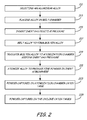
- FIG. 2 is a block flow diagram of the process for producing fine aluminum alloy powder.
- FIG. 1 shows production apparatus, 10, for production of fine aluminum alloy powder.
- the aluminum alloy can be any alloy but it has been discovered that the glassy devitrified alloys such as those disclosed in co-owned U.S. Patents No, 6,974,510 and 7,413,621 , are capable of being formed into powder using the system and method of this invention. Both high strength and ductility of these alloys is maintained by the system and method.
- a melt chamber 11 has a closed top 13 and is filled with an inert gas such as argon via gas inlet 15 from inert gas source 44.
- Compressor 45 provides the inert gas to the melt chamber 11 and other parts of apparatus 10, including 29, 33, 37, and 41. This gas circulates through a dryer to make sure the dew point is between -35 °F (-37.2 °C) and -110 °F (-78.9 °C) and through an oxygen getter to make sure the oxygen is between 10 to 50 ppm.
- a pressure release valve is used to preclude over-pressurization of the system 10.
- a valve system is used to route the gas to gas source 44.
- a wash heat is where, in this case, pure aluminum might be atomized to getter oxygen and hydrogen, thereby establishing the correct enviromnent in system 10.
- the aluminum alloys would then be atomized after this wash heat.
- the problem with this approach is the possibility of cross-contamination, creating metallurgical flaws in the consolidated alloy.
- a bottom pour crucible 21 is located in melt chamber 11.
- An additional inert gas inlet 23 provides the inert gas for atomization.
- a stopper rod 26 controls the opening and closing of a hole at the bottom 27 of crucible 21.
- the powder produced from molten metal that exits the hole in crucible bottom 27 enters an atomization chamber 29, which is a conical hopper for catching the exiting powder.
- Chamber 29 includes an isolation valve 31 that controls access of powder from chamber 29 to catch tank 33.
- Catch tank 33 also has a valve 31a that separates the catch tank from chamber 29 when connected to the chamber, and from the surrounding air when not connected.
- melt chamber 11 Also part of melt chamber 11 is an outlet 35 that receives powder from the top of atomization chamber 29. Powder is transferred to a first cyclone catch tank 37, to which access is controlled by isolation valve 39. First cyclone catch tank 37 also has an isolation valve 39a that separates the catch tank 37 from chamber 29 when connected to the chamber, and from the surrounding air when not connected. Tank 37 catches finer powder than that in atomization chamber 29, thus improving yield. Outlet 35 further transfers powder to a second cyclone catch tank 41, again controlled by isolation valve 43. Second cyclone catch tank 41 catches the finest powder produced in atomization chamber 29. Catch tank 41 also has an isolation valve 43a that separates the catch tank from chamber 29 when connected, and from the surrounding air when not connected. When all catch tanks are full of powder, this valve system allows them to be removed both during and after runs, and a new tank added where the new tank has an internal environment conditioned to be acceptable to that in the atomization system 10.
- melt chamber 11 Closed top 13 of melt chamber 11 insures that inert gas exerting a positive pressure will prevent moist or humid air from entering crucible 21. It is desirable to have the dew point in melt chamber 11, and thus in crucible 21, be as low as possible. The dew point can range from -35 °F to -85 °F (-37.2 °C to -65 °C), preferably as low as -110 °F (-78.9 °C). In addition to dry, inert gas in the crucible area, it is desirable to circulate dry gas in atomization chamber 29 and catch tanks 33, 37, and 41 via an inert gas inlet.
- the dew point in atomization chamber 29 and catch tanks 33, 37, and 41 should also be about -35 °F to -85 °F (-37.2 °C to -65 °C), preferably as low as -110 °F (-78.9 °C).
- the weight of metal being atomized should be between 100 pounds (45 kg) and 500 pounds (227 kg), with 300 pounds (136 kg) normally being sufficient, given the size and efficiency of the equipment.
- Gas from gas source 17 is pressurized by a high pressure compressor 19 and this gas atomizes the molten metal stream via inlets 23. To minimize cost, particularly where helium is involved, this gas is recycled back into 17. The recycled gas is passed through a dryer to make sure the dew point is between -35 °F (-37.2 °C) and -110 °F (-78.9 °C) and through an oxygen getter to make sure the oxygen is between 10 to 50 ppm. To preclude over-pressurization of the system 10, a pressure release valve is used. A valve system is used to route the gas to gas source 17.
- Powder formed is captured in catch tank 33 and in first cyclone catch tank 37 and second cyclone catch tank 41.
- Pressure gauges may be connected to tanks 33, 37 and 41 so their respective valves can be closed to determine that the tanks are capable of holding gas from the atomization process at a pressure greater than ambient. Closing the valve and measuring the pressure will determine if there is leakage of gas from the tanks. Leakage will result in contamination of the powder.
- these tanks can be pressurized by an inert gas such as dry argon, nitrogen, or a helium containing mixture of gases.
- the powder As the powder is collected in tanks 33, 37 and 41, it is at a high temperature, such as 500 °F (260 °C) and cooling jackets may be used, such as by placement in intimate contact with the tanks and using water or colder coolants such as dry ice.
- a high temperature such as 500 °F (260 °C) and cooling jackets may be used, such as by placement in intimate contact with the tanks and using water or colder coolants such as dry ice.
- FIG. 2 is a block flow diagram of the method of this invention.
- the aluminum alloy is selected (Step 211) and placed in a melt chamber (Step 213) where inert gas, such as argon or nitrogen, is added to provide a positive inert gas pressure (Step 215).
- inert gas such as argon or nitrogen
- the alloy is then melted to form a molten alloy (Step 217) either in the atomization crucible, or in an adjacent melt crucible where it is transferred to the atomization crucible, while maintaining the positive inert gas pressure (Step 219).
- the molten alloy is atomized to produce fine powder (Step 221) in the inert atmosphere.
- the powder is then captured in the chamber catch tank (Step 223) and, optionally as noted above, to one or more cyclone tanks (Step 225).
- Atomization of the powder is done in a manner to provide for high retention of the glassy state in materials having a high solute content or to provide for maintaining the nanocrystalline microstructure of materials having a lower solute content.
- the variables that are controlled during atomization include the atomization gas, melt temperature, powder passivation, and atomization rate.
- the atomization gas variables include oxygen content, dew point, gas pressure and gas composition.
- the oxygen content should be between 10 to 50 ppm.
- the dew point as noted above, should be about -35 °F to -85 °F (-37.2 °C to -65 °C), preferably as low as -110 °F (-78.9 °C).
- the gas pressure can vary anywhere between 50 to 1,000 psi (345 kPa to 6900 kPa), with higher pressure being desirable because the gas imparts more energy into the melt stream and results in production of finer powder.
- the gas content by volume can be a helium (He)/inert gas (IG) combination with a He/IG ratio of 100 in 3 /0 to 50 in 3 /50 in 3 .
- He helium
- IG inert gas
- More helium is better because helium conducts heat away from the molten powder more efficiently than other gasses. It is noted that helium is more expensive than other gasses; hence, the need for a recirculation system.
- the melt temperature is established through the use of Differential Scanning Calorimity (DSC).
- DSC trace can define the temperature whereby the highest melting point phase goes into liquid solution.
- this upper bound temperature can vary between 1600 °F (871 °C) and 2200 °F (1204 °C). This temperature range keeps all phases in liquid solution and prevents nozzle clogging.
- superheat an additional increment of temperature, known as superheat, can be added to guarantee that the temperature does not drop below the critical level.
- Superheat can range from about 50 °F (10 °C) to about 400 °F (204.4 °C).
- the atomization rate is defined as the number of pounds of powder produced per minute. For a given gas flow rate, the lower the powder produced per minute, the higher will be the gas-to-metal ratio, and the higher cooling rate and thus better mechanical properties. For good mechanical properties, powder production rate can vary between 0.1 to 5.0 pounds per minute (45 to 2270 grams per minute), with 1 pound per minute (450 grams per minute) being preferable. If the atomization rate is viewed in terms of the gas-to-metal ratio, the optimum rate for good mechanical properties has been found to be 0.1 to 10 pounds (45 to 4500 grams) of gas per pound (450 grams) of powder.
- the powder is also subjected to powder passivation, whereby a thin aluminum oxide shell is placed on top of the aluminum powder particles. This is done to prevent rapid oxidation of aluminum powder, which can be highly explosive.
- Powder passivation is accomplished by adding very dry oxygen during an atomization run, or, alternatively, by adding very dry oxygen after the powder has cooled down to room temperature. In the former case, the amount of oxygen added ranges from 10 to 400 ppm to produce an oxide layer of as much as 15 to 25 nm. If oxygen is added at room temperature, the amount can range from 10 to 1000 ppm, resulting in a thinner oxide layer of 3 to 5 nm.
Landscapes
- Chemical & Material Sciences (AREA)
- Engineering & Computer Science (AREA)
- Materials Engineering (AREA)
- Mechanical Engineering (AREA)
- Metallurgy (AREA)
- Organic Chemistry (AREA)
- Crystallography & Structural Chemistry (AREA)
- Manufacture Of Metal Powder And Suspensions Thereof (AREA)
Abstract
Description
- Aluminum alloys are important in many industries. Glassy Al-based alloys and their devitrified derivatives are currently being considered for applications in the aerospace industry. These alloys involve the addition of rare earth and transition metal elements. These alloys have high strength and, when processed appropriately, have high ductility.
- Because these alloys are processed via the powder metallurgy approach, one of the key requirements for high ductility is control of the uptake of hydrogen. While all Al-based alloys are sensitive to hydrogen, alloys containing rare earth elements are particularly susceptible to the effects of hydrogen during alloy production.
- The powder for Al-based powder metallurgy alloys can be produced using gas-atomization. When atomized powder of pure aluminum or Al-based alloys is produced, the process normally involves the use of an inert gas such as nitrogen that is injected into a molten metal stream at high pressure. The gas is not recycled because it is relatively inexpensive. However, in the case of prior alloys, no concern has been made for oxygen and/or hydrogen uptake because the presence of oxygen and/or hydrogen does not affect the strength of prior alloys. From the standpoint of ductility, the prior art involves the removal of hydrogen and oxygen during high temperature degassing. This approach will not work for glassy or partially devitrified nano-scale microstructures because of the thermal instability of such microstructures while in powder form.
- Al-based alloys such as Al-Y-Ni-Co alloys are devitrified glass-forming aluminum alloys that derive their strength from a nanometer-sized grain structure and nanometer-sized intermetallic phase or phases. Examples of such alloys are disclosed in co-owned
U.S. Patents No, 6,974,510 and7,413,621 , the disclosures of which are incorporated herein by reference in their entirety. - Owing to the reactive nature of these alloys, i.e., the presence of rare earth elements such as Y, the presence of oxygen can lead to fires and/or explosions. In addition, the presence of hydrogen destroys the ductility of these alloys. When the alloy is a glassy Al-based alloy, the high temperatures required for degassing these materials in powder form brings about an almost instantaneous devitrification so that the benefits of the glassy state are lost. Also, partially devitrified derivatives of the glassy state produce nanocrystalline microstructures that have mechanical properties that cannot be obtained when starting out with powder in the crystalline state.
- It is necessary to find an alternative process for production of these highly reactive Al-based alloys.
- The present invention includes a process in which rare earth containing Al-based alloys are isolated to prevent oxygen and hydrogen pickup. The process includes the gettering of oxygen and lowering the dew point of the atmosphere above the molten metal and throughout the rest of the system to -35 °F to -85 °F (-37.2 °C to -65 °C), preferably as low as -110 °F (-78.9 °C). When this is done, atomization of the metal into powder is performed and thereafter caught in catch tanks at the bottom of the atomization chamber. The catch tanks also have the reduced oxygen and dew point noted above. The catch tanks are cooled to prevent undesired devitrification or coarsening of fine microstructures in the powder. These catch tanks are isolated by valves from the surrounding environment to preclude post-atomization contamination from exogenous matter as well as oxygen and hydrogen.
- Additional process requirements include control of the melt temperature with an upper limit of 1600 °F (871 °C) to 2200 °F (1204 °C), and the powder atomization rate is controlled to be about 0.1 to 5.0 pounds (45.4 to 2270 grams) of powder produced per minute. A gas to metal ratio is controlled to be between about 0.1 to 10 pounds (45.4 to 4540 grams) of gas per pound of powder. Finally, the powder particle size is controlled by controlling the nozzle size, because for any given gas flow, a smaller nozzle will allow for a higher gas-to-metal ratio that provides for finer powder and better mechanical properties. The nozzle size is between 0.05 and 0.25 inches (0.0254 to 0.635 cm.), resulting in a high percentage of the powder having a size less than -625 mesh (0.1 to 45 µm).
- The present invention provides a system for producing atomized powder for glassy or partially devitrified aluminum-based alloys, comprising: a melt chamber having a closed top, including an inert gas inlet for providing a positive pressure of inert gas therein; a source of inert gas adapted to supply inert gas to the inlet; a crucible for melting aluminum alloy therein, the crucible having an outlet for delivering molten aluminum alloy; an atomization chamber positioned to receive molten aluminum alloy from the crucible and produce fine aluminum alloy powder from the molten alloy, including inert gas inlets for maintaining a positive pressure of inert gas; inert gas inlets on the atomization chamber for making powder; and at least one catch tank for receiving powder produced in the atomization chamber while maintaining a positive pressure of inert gas.
- In another aspect the present invention provides a method for producing atomized powder for glassy aluminum-based alloys, comprising the steps of: providing a positive pressure of inert gas in a melt chamber having a closed top using an inert gas inlet; supplying inert gas to the inlet from a source of inert gas; melting an aluminum alloy in a crucible and delivering molten aluminum alloy out of the crucible; receiving the molten aluminum alloy from the crucible into an atomization chamber and forming fine aluminum alloy powder from the molten alloy, while maintaining a positive pressure of inert gas in the atomization chamber; and receiving powder produced in the atomization chamber in at least one catch tank while maintaining a positive pressure of inert gas therein.
- Certain preferred embodiments will now be described in greater detail by way of example only and with reference to the accompanying drawings.
-
FIG. 1 is a diagram illustrating a production apparatus for fine aluminum alloy powder. -
FIG. 2 is a block flow diagram of the process for producing fine aluminum alloy powder. -
FIG. 1 shows production apparatus, 10, for production of fine aluminum alloy powder. The aluminum alloy can be any alloy but it has been discovered that the glassy devitrified alloys such as those disclosed in co-ownedU.S. Patents No, 6,974,510 and7,413,621 , are capable of being formed into powder using the system and method of this invention. Both high strength and ductility of these alloys is maintained by the system and method. - A
melt chamber 11 has a closedtop 13 and is filled with an inert gas such as argon viagas inlet 15 frominert gas source 44.Compressor 45 provides the inert gas to themelt chamber 11 and other parts ofapparatus 10, including 29, 33, 37, and 41. This gas circulates through a dryer to make sure the dew point is between -35 °F (-37.2 °C) and -110 °F (-78.9 °C) and through an oxygen getter to make sure the oxygen is between 10 to 50 ppm. To preclude over-pressurization of thesystem 10, a pressure release valve is used. A valve system is used to route the gas togas source 44. The benefit of circulating the gas prior to melting the alloy is not only the establishment of the correct melt conditions, but to preclude the cost of a so-called wash heat. A wash heat is where, in this case, pure aluminum might be atomized to getter oxygen and hydrogen, thereby establishing the correct enviromnent insystem 10. The aluminum alloys would then be atomized after this wash heat. The problem with this approach is the possibility of cross-contamination, creating metallurgical flaws in the consolidated alloy. Alternatively, one could atomize the aluminum alloy of choice, but rare earth containing alloys are quite expensive, and this adds cost to the overall production process, both in materials and labor and machine time. A bottom pour crucible 21 is located inmelt chamber 11. An additionalinert gas inlet 23 provides the inert gas for atomization. Astopper rod 26 controls the opening and closing of a hole at thebottom 27 ofcrucible 21. - The powder produced from molten metal that exits the hole in
crucible bottom 27 enters anatomization chamber 29, which is a conical hopper for catching the exiting powder.Chamber 29 includes anisolation valve 31 that controls access of powder fromchamber 29 to catchtank 33.Catch tank 33 also has avalve 31a that separates the catch tank fromchamber 29 when connected to the chamber, and from the surrounding air when not connected. - Also part of
melt chamber 11 is anoutlet 35 that receives powder from the top ofatomization chamber 29. Powder is transferred to a firstcyclone catch tank 37, to which access is controlled byisolation valve 39. Firstcyclone catch tank 37 also has anisolation valve 39a that separates thecatch tank 37 fromchamber 29 when connected to the chamber, and from the surrounding air when not connected.Tank 37 catches finer powder than that inatomization chamber 29, thus improving yield.Outlet 35 further transfers powder to a secondcyclone catch tank 41, again controlled byisolation valve 43. Secondcyclone catch tank 41 catches the finest powder produced inatomization chamber 29.Catch tank 41 also has anisolation valve 43a that separates the catch tank fromchamber 29 when connected, and from the surrounding air when not connected. When all catch tanks are full of powder, this valve system allows them to be removed both during and after runs, and a new tank added where the new tank has an internal environment conditioned to be acceptable to that in theatomization system 10. - Closed top 13 of
melt chamber 11 insures that inert gas exerting a positive pressure will prevent moist or humid air from enteringcrucible 21. It is desirable to have the dew point inmelt chamber 11, and thus incrucible 21, be as low as possible. The dew point can range from -35 °F to -85 °F (-37.2 °C to -65 °C), preferably as low as -110 °F (-78.9 °C). In addition to dry, inert gas in the crucible area, it is desirable to circulate dry gas inatomization chamber 29 and catchtanks atomization chamber 29 and catchtanks - Once the dew point of the system has been lowered, the metal in
crucible 21 is melted and atomization is begun. Gas fromgas source 17 is pressurized by ahigh pressure compressor 19 and this gas atomizes the molten metal stream viainlets 23. To minimize cost, particularly where helium is involved, this gas is recycled back into 17. The recycled gas is passed through a dryer to make sure the dew point is between -35 °F (-37.2 °C) and -110 °F (-78.9 °C) and through an oxygen getter to make sure the oxygen is between 10 to 50 ppm. To preclude over-pressurization of thesystem 10, a pressure release valve is used. A valve system is used to route the gas togas source 17. Powder formed is captured incatch tank 33 and in firstcyclone catch tank 37 and secondcyclone catch tank 41. Depending on the system, more or fewer cyclone catch tanks may be used as needed. Pressure gauges may be connected totanks - As the powder is collected in
tanks -
FIG. 2 is a block flow diagram of the method of this invention. The aluminum alloy is selected (Step 211) and placed in a melt chamber (Step 213) where inert gas, such as argon or nitrogen, is added to provide a positive inert gas pressure (Step 215). The alloy is then melted to form a molten alloy (Step 217) either in the atomization crucible, or in an adjacent melt crucible where it is transferred to the atomization crucible, while maintaining the positive inert gas pressure (Step 219). The molten alloy is atomized to produce fine powder (Step 221) in the inert atmosphere. The powder is then captured in the chamber catch tank (Step 223) and, optionally as noted above, to one or more cyclone tanks (Step 225). - Atomization of the powder is done in a manner to provide for high retention of the glassy state in materials having a high solute content or to provide for maintaining the nanocrystalline microstructure of materials having a lower solute content. The variables that are controlled during atomization include the atomization gas, melt temperature, powder passivation, and atomization rate.
- The atomization gas variables include oxygen content, dew point, gas pressure and gas composition. The oxygen content should be between 10 to 50 ppm. The dew point, as noted above, should be about -35 °F to -85 °F (-37.2 °C to -65 °C), preferably as low as -110 °F (-78.9 °C). The gas pressure can vary anywhere between 50 to 1,000 psi (345 kPa to 6900 kPa), with higher pressure being desirable because the gas imparts more energy into the melt stream and results in production of finer powder.
- For a given metal flow, higher gas pressure results in a higher flow rate, which yields a higher gas-to-metal ratio and results in faster cooling to yield more glassy powder or finer nanocrystalline microstructures. The gas content by volume can be a helium (He)/inert gas (IG) combination with a He/IG ratio of 100 in3/0 to 50 in3/50 in3. More helium is better because helium conducts heat away from the molten powder more efficiently than other gasses. It is noted that helium is more expensive than other gasses; hence, the need for a recirculation system.
- The melt temperature is established through the use of Differential Scanning Calorimity (DSC). A DSC trace can define the temperature whereby the highest melting point phase goes into liquid solution. Depending on the alloy composition, this upper bound temperature can vary between 1600 °F (871 °C) and 2200 °F (1204 °C). This temperature range keeps all phases in liquid solution and prevents nozzle clogging. To insure prevention of nozzle clogging, an additional increment of temperature, known as superheat, can be added to guarantee that the temperature does not drop below the critical level. Superheat can range from about 50 °F (10 °C) to about 400 °F (204.4 °C).
- The atomization rate is defined as the number of pounds of powder produced per minute. For a given gas flow rate, the lower the powder produced per minute, the higher will be the gas-to-metal ratio, and the higher cooling rate and thus better mechanical properties. For good mechanical properties, powder production rate can vary between 0.1 to 5.0 pounds per minute (45 to 2270 grams per minute), with 1 pound per minute (450 grams per minute) being preferable. If the atomization rate is viewed in terms of the gas-to-metal ratio, the optimum rate for good mechanical properties has been found to be 0.1 to 10 pounds (45 to 4500 grams) of gas per pound (450 grams) of powder.
- The powder is also subjected to powder passivation, whereby a thin aluminum oxide shell is placed on top of the aluminum powder particles. This is done to prevent rapid oxidation of aluminum powder, which can be highly explosive. Powder passivation is accomplished by adding very dry oxygen during an atomization run, or, alternatively, by adding very dry oxygen after the powder has cooled down to room temperature. In the former case, the amount of oxygen added ranges from 10 to 400 ppm to produce an oxide layer of as much as 15 to 25 nm. If oxygen is added at room temperature, the amount can range from 10 to 1000 ppm, resulting in a thinner oxide layer of 3 to 5 nm.
- While the invention has been described with reference to an exemplary embodiment(s), it will be understood by those skilled in the art that various changes may be made and equivalents may be substituted for elements thereof without departing from the scope of the invention. In addition, many modifications may be made to adapt a particular situation or material to the teachings of the invention without departing from the essential scope thereof. Therefore, it is intended that the invention not be limited to the particular embodiment(s) disclosed, but that the invention will include all embodiments falling within the scope of the appended claims.
- The following clause sets out features of the invention which may not presently be claimed in this application, but which may form the basis for future amendment or a divisional application.
- 1. A method for producing atomized powder devitrified glass-forming aluminum alloys having a nanometer-sized grain structure and nanometer-sized intermetallic phase or phases, comprising the steps of:
- melting the alloy in a chamber having a positive pressure of inert gas;
- melting an aluminum alloy in a crucible adapted to heat the alloy to an upper temperature ranging from 1600 °F (871 °C) to 2200 °F (1204 °C), wherein the atomization chamber is maintained at a dew point of 35 °F to -110 °F (-37.2 °C to -78.9 °C);
- atomize the molten ally to a fine aluminum alloy powder; and
- collecting the powder produced by atomization while maintaining a positive pressure of inert gas.
Claims (15)
- A system for producing atomized powder for glassy or partially devitrified aluminum-based alloys, comprising:a melt chamber (11) having a closed top (13), including an inert gas inlet (15) for providing a positive pressure of inert gas therein;a source of inert gas (44) adapted to supply inert gas to the inlet;a crucible (21) for melting aluminum alloy therein, the crucible having an outlet for delivering molten aluminum alloy;an atomization chamber (29) positioned to receive molten aluminum alloy from the crucible and produce fine aluminum alloy powder from the molten alloy, including inert gas inlets (23) for maintaining a positive pressure of inert gas;inert gas inlets on the atomization chamber for making powder; andat least one catch tank (33, 37, 41) for receiving powder produced in the atomization chamber while maintaining a positive pressure of inert gas.
- The system of claim 1, wherein a first catch tank (33) is disposed for first receipt of the powder.
- The system of claim 2, wherein a first cyclone catch tank (37) is disposed to receive powder downstream from the first catch tank, and preferably wherein a second cyclone catch tank (41) is disposed to receive powder downstream from the first cyclone catch tank.
- The system of claim 3, wherein the first catch tank (33), the first cyclone tank (37) and the second cyclone tank (41) have isolation valves (31, 39, 43) for closing access thereto.
- The system of any preceding claim, wherein the atomization chamber (29) is arranged to be maintained at a dew point of 35 °F to -110 °F (-37.2 °C to -78.9 °C), and wherein the atomization chamber is preferably arranged to have a gas composition of a mixture of helium and at least one inert gas wherein the ratio of helium to inert gas ranges from 100 in3/0 to 50 in3/50 in3 .
- The system of any preceding claim, the crucible (21) is adapted to heat the alloy to an upper temperature ranging from 1600 °F (871 °C) to 2200 °F (1204 °C).
- The system of any preceding claim, wherein the aluminum alloy is a devitrified glass-forming aluminum alloy having a nanometer-sized grain structure and nanometer-sized intermetallic phase or phases.
- A method for producing atomized powder for glassy aluminum-based alloys, comprising the steps of:providing a positive pressure of inert gas in a melt chamber (11) having a closed top using an inert gas inlet (15);supplying inert gas to the inlet from a source (44) of inert gas;melting an aluminum alloy in a crucible (21) and delivering molten aluminum alloy out of the crucible;receiving the molten aluminum alloy from the crucible into an atomization chamber (29) and forming fine aluminum alloy powder from the molten alloy, while maintaining a positive pressure of inert gas in the atomization chamber; andreceiving powder produced in the atomization chamber in at least one catch tank (33, 37, 41) while maintaining a positive pressure of inert gas therein.
- The method of claim 8, wherein the powder is transferred from the atomization chamber (29) to a first catch tank (33).
- The method of claim 9, wherein a portion of the powder is transferred from the atomization chamber (29) downstream from the first catch tank (33) to a first cyclone catch tank (37).
- The method of claim 10, wherein an additional portion of the powder is transferred from the atomization chamber (29) downstream from the first cyclone catch tank (37) to a second cyclone catch tank (41), and wherein the first catch tank, the first cyclone tank and the second cyclone tank have isolation valves (31, 39, 43) for closing access thereto.
- The method of any of claims 8 to 11, wherein the atomization chamber (29) is maintained at a dew point of 35 °F to -110 °F (-37.2 °C to -78.9 °C).
- The method of any of claims 8 to 12, the atomization chamber (29) has a gas composition of a mixture of helium and at least one inert gas wherein the ratio of helium to inert gas ranges from 100 in3/0 to 50 in3/50 in3.
- The method of any of claims 8 to 13, wherein the crucible (21) is adapted to heat the alloy to an upper temperature ranging from 1600 °F (871 °C) to 2200 °F (1204 °C).
- The method of any of claims 8 to 14, wherein the aluminum alloy is a devitrified glass-forming aluminum alloy having a nanometer-sized grain structure and nanometer-sized intermetallic phase or phases.
Applications Claiming Priority (1)
| Application Number | Priority Date | Filing Date | Title |
|---|---|---|---|
| US13/169,207 US20120325051A1 (en) | 2011-06-27 | 2011-06-27 | Production of atomized powder for glassy aluminum-based alloys |
Publications (3)
| Publication Number | Publication Date |
|---|---|
| EP2540420A2 true EP2540420A2 (en) | 2013-01-02 |
| EP2540420A3 EP2540420A3 (en) | 2013-11-13 |
| EP2540420B1 EP2540420B1 (en) | 2015-11-04 |
Family
ID=45930617
Family Applications (1)
| Application Number | Title | Priority Date | Filing Date |
|---|---|---|---|
| EP12162575.0A Active EP2540420B1 (en) | 2011-06-27 | 2012-03-30 | Production of atomized powder for glassy aluminum-based alloys |
Country Status (2)
| Country | Link |
|---|---|
| US (1) | US20120325051A1 (en) |
| EP (1) | EP2540420B1 (en) |
Families Citing this family (14)
| Publication number | Priority date | Publication date | Assignee | Title |
|---|---|---|---|---|
| WO2015006466A1 (en) | 2013-07-10 | 2015-01-15 | United Technologies Corporation | Aluminum alloys and manufacture methods |
| US9970079B2 (en) * | 2014-04-18 | 2018-05-15 | Apple Inc. | Methods for constructing parts using metallic glass alloys, and metallic glass alloy materials for use therewith |
| US10161025B2 (en) | 2014-04-30 | 2018-12-25 | Apple Inc. | Methods for constructing parts with improved properties using metallic glass alloys |
| US9849504B2 (en) | 2014-04-30 | 2017-12-26 | Apple Inc. | Metallic glass parts including core and shell |
| US10056541B2 (en) | 2014-04-30 | 2018-08-21 | Apple Inc. | Metallic glass meshes, actuators, sensors, and methods for constructing the same |
| US10000837B2 (en) | 2014-07-28 | 2018-06-19 | Apple Inc. | Methods and apparatus for forming bulk metallic glass parts using an amorphous coated mold to reduce crystallization |
| AU2016297700B2 (en) * | 2015-07-17 | 2021-08-12 | Ap&C Advanced Powders & Coatings Inc. | Plasma atomization metal powder manufacturing processes and systems therefore |
| EP4640343A1 (en) | 2015-10-29 | 2025-10-29 | AP&C Advanced Powders And Coatings Inc. | Metal powder atomization manufacturing processes |
| EP4159345A1 (en) | 2016-04-11 | 2023-04-05 | AP&C Advanced Powders And Coatings Inc. | Reactive metal powders in-flight heat treatment processes |
| CN106670479B (en) * | 2017-01-16 | 2017-11-10 | 西安科技大学 | A kind of adjustable atomization bucket based on water atomization legal system powder |
| CN113020609A (en) * | 2021-03-03 | 2021-06-25 | 内蒙古旭阳新材料有限公司 | Low-energy-consumption high-yield spherical aluminum powder production system and method |
| RU2754258C1 (en) * | 2021-03-16 | 2021-08-31 | Федеральное государственное бюджетное учреждение науки Институт химии твердого тела Уральского отделения Российской академии наук | Method for producing aluminum-based powder for 3d printing |
| CN113275578B (en) * | 2021-05-10 | 2023-02-03 | 内蒙古旭阳新材料有限公司 | Production equipment and method for passivated aluminum powder |
| CN113145854B (en) * | 2021-06-10 | 2025-03-07 | 江苏智仁景行新材料研究院有限公司 | A vacuum electrode induction melting double-flow gas atomization metal powder device |
Citations (1)
| Publication number | Priority date | Publication date | Assignee | Title |
|---|---|---|---|---|
| US6974510B2 (en) | 2003-02-28 | 2005-12-13 | United Technologies Corporation | Aluminum base alloys |
Family Cites Families (3)
| Publication number | Priority date | Publication date | Assignee | Title |
|---|---|---|---|---|
| DE3730147A1 (en) * | 1987-09-09 | 1989-03-23 | Leybold Ag | METHOD FOR PRODUCING POWDER FROM MOLTEN SUBSTANCES |
| US5277705A (en) * | 1992-12-30 | 1994-01-11 | Iowa State University Research Foundation, Inc. | Powder collection apparatus/method |
| US5433978A (en) * | 1993-09-27 | 1995-07-18 | Iowa State University Research Foundation, Inc. | Method of making quasicrystal alloy powder, protective coatings and articles |
-
2011
- 2011-06-27 US US13/169,207 patent/US20120325051A1/en not_active Abandoned
-
2012
- 2012-03-30 EP EP12162575.0A patent/EP2540420B1/en active Active
Patent Citations (2)
| Publication number | Priority date | Publication date | Assignee | Title |
|---|---|---|---|---|
| US6974510B2 (en) | 2003-02-28 | 2005-12-13 | United Technologies Corporation | Aluminum base alloys |
| US7413621B2 (en) | 2003-02-28 | 2008-08-19 | United Technologies Corporation | Aluminum base alloys |
Also Published As
| Publication number | Publication date |
|---|---|
| EP2540420A3 (en) | 2013-11-13 |
| EP2540420B1 (en) | 2015-11-04 |
| US20120325051A1 (en) | 2012-12-27 |
Similar Documents
| Publication | Publication Date | Title |
|---|---|---|
| EP2540420B1 (en) | Production of atomized powder for glassy aluminum-based alloys | |
| US5310165A (en) | Atomization of electroslag refined metal | |
| CN103801687B (en) | The non-fusible method for preparing metallic-alloy articles | |
| US8778098B2 (en) | Method for producing high strength aluminum alloy powder containing L12 intermetallic dispersoids | |
| US4626278A (en) | Tandem atomization method for ultra-fine metal powder | |
| US4897111A (en) | Method for the manufacture of powders from molten materials | |
| CN108188408B (en) | A kind of spherical atomized magnesium-zinc amorphous alloy powder and preparation method thereof | |
| JPH0135881B2 (en) | ||
| Heidloff et al. | Advanced gas atomization processing for Ti and Ti alloy powder manufacturing | |
| JPH0748609A (en) | Method for producing particles by gas spray synthesis of heat-resistant compound or intermetallic compound and supersaturated solid solution | |
| US20230356296A1 (en) | Device and method for producing metal powders | |
| US20140076463A1 (en) | Master alloy production for glassy aluminum-based alloys | |
| JP2004183049A (en) | Method for producing fine metal powder by gas atomization method and apparatus for producing fine metal powder | |
| US5263689A (en) | Apparatus for making alloy power | |
| WO2001062419A1 (en) | Clean melt nucleated casting systems and methods with cooling of the casting | |
| JP2642060B2 (en) | Method and apparatus for producing reactive metal particles | |
| US6461403B1 (en) | Apparatus and method for the formation of uniform spherical particles | |
| eee AeS | i SAAAAAA | |
| US4735652A (en) | Process for producing agglomerates of aluminum based material | |
| US7097688B1 (en) | Method for producing silicon based alloys in atomized form | |
| JPH07102307A (en) | Flake powder material manufacturing method | |
| Tassa et al. | Powders for Additive Manufacturing: From Design to Certification | |
| JPS60138008A (en) | Production of metallic powder | |
| US4043716A (en) | Apparatus for providing a stream of molten metal from a metallic ingot | |
| CN113210616B (en) | Ultra-fine Ti 2 AlNb alloy powder and preparation method and application thereof |
Legal Events
| Date | Code | Title | Description |
|---|---|---|---|
| PUAI | Public reference made under article 153(3) epc to a published international application that has entered the european phase |
Free format text: ORIGINAL CODE: 0009012 |
|
| AK | Designated contracting states |
Kind code of ref document: A2 Designated state(s): AL AT BE BG CH CY CZ DE DK EE ES FI FR GB GR HR HU IE IS IT LI LT LU LV MC MK MT NL NO PL PT RO RS SE SI SK SM TR |
|
| AX | Request for extension of the european patent |
Extension state: BA ME |
|
| PUAL | Search report despatched |
Free format text: ORIGINAL CODE: 0009013 |
|
| AK | Designated contracting states |
Kind code of ref document: A3 Designated state(s): AL AT BE BG CH CY CZ DE DK EE ES FI FR GB GR HR HU IE IS IT LI LT LU LV MC MK MT NL NO PL PT RO RS SE SI SK SM TR |
|
| AX | Request for extension of the european patent |
Extension state: BA ME |
|
| RIC1 | Information provided on ipc code assigned before grant |
Ipc: B22F 9/00 20060101AFI20131010BHEP Ipc: C22C 1/04 20060101ALI20131010BHEP Ipc: C22C 45/08 20060101ALI20131010BHEP Ipc: B22F 9/08 20060101ALI20131010BHEP |
|
| 17P | Request for examination filed |
Effective date: 20140513 |
|
| RBV | Designated contracting states (corrected) |
Designated state(s): AL AT BE BG CH CY CZ DE DK EE ES FI FR GB GR HR HU IE IS IT LI LT LU LV MC MK MT NL NO PL PT RO RS SE SI SK SM TR |
|
| GRAP | Despatch of communication of intention to grant a patent |
Free format text: ORIGINAL CODE: EPIDOSNIGR1 |
|
| INTG | Intention to grant announced |
Effective date: 20150515 |
|
| GRAS | Grant fee paid |
Free format text: ORIGINAL CODE: EPIDOSNIGR3 |
|
| GRAA | (expected) grant |
Free format text: ORIGINAL CODE: 0009210 |
|
| AK | Designated contracting states |
Kind code of ref document: B1 Designated state(s): AL AT BE BG CH CY CZ DE DK EE ES FI FR GB GR HR HU IE IS IT LI LT LU LV MC MK MT NL NO PL PT RO RS SE SI SK SM TR |
|
| REG | Reference to a national code |
Ref country code: GB Ref legal event code: FG4D |
|
| REG | Reference to a national code |
Ref country code: CH Ref legal event code: EP |
|
| REG | Reference to a national code |
Ref country code: AT Ref legal event code: REF Ref document number: 758850 Country of ref document: AT Kind code of ref document: T Effective date: 20151115 |
|
| REG | Reference to a national code |
Ref country code: IE Ref legal event code: FG4D |
|
| REG | Reference to a national code |
Ref country code: DE Ref legal event code: R096 Ref document number: 602012012080 Country of ref document: DE |
|
| REG | Reference to a national code |
Ref country code: FR Ref legal event code: PLFP Year of fee payment: 5 |
|
| REG | Reference to a national code |
Ref country code: NL Ref legal event code: MP Effective date: 20151104 |
|
| REG | Reference to a national code |
Ref country code: LT Ref legal event code: MG4D |
|
| REG | Reference to a national code |
Ref country code: AT Ref legal event code: MK05 Ref document number: 758850 Country of ref document: AT Kind code of ref document: T Effective date: 20151104 |
|
| PG25 | Lapsed in a contracting state [announced via postgrant information from national office to epo] |
Ref country code: NL Free format text: LAPSE BECAUSE OF FAILURE TO SUBMIT A TRANSLATION OF THE DESCRIPTION OR TO PAY THE FEE WITHIN THE PRESCRIBED TIME-LIMIT Effective date: 20151104 Ref country code: NO Free format text: LAPSE BECAUSE OF FAILURE TO SUBMIT A TRANSLATION OF THE DESCRIPTION OR TO PAY THE FEE WITHIN THE PRESCRIBED TIME-LIMIT Effective date: 20160204 Ref country code: IT Free format text: LAPSE BECAUSE OF FAILURE TO SUBMIT A TRANSLATION OF THE DESCRIPTION OR TO PAY THE FEE WITHIN THE PRESCRIBED TIME-LIMIT Effective date: 20151104 Ref country code: HR Free format text: LAPSE BECAUSE OF FAILURE TO SUBMIT A TRANSLATION OF THE DESCRIPTION OR TO PAY THE FEE WITHIN THE PRESCRIBED TIME-LIMIT Effective date: 20151104 Ref country code: LT Free format text: LAPSE BECAUSE OF FAILURE TO SUBMIT A TRANSLATION OF THE DESCRIPTION OR TO PAY THE FEE WITHIN THE PRESCRIBED TIME-LIMIT Effective date: 20151104 Ref country code: IS Free format text: LAPSE BECAUSE OF FAILURE TO SUBMIT A TRANSLATION OF THE DESCRIPTION OR TO PAY THE FEE WITHIN THE PRESCRIBED TIME-LIMIT Effective date: 20160304 Ref country code: ES Free format text: LAPSE BECAUSE OF FAILURE TO SUBMIT A TRANSLATION OF THE DESCRIPTION OR TO PAY THE FEE WITHIN THE PRESCRIBED TIME-LIMIT Effective date: 20151104 |
|
| PG25 | Lapsed in a contracting state [announced via postgrant information from national office to epo] |
Ref country code: PL Free format text: LAPSE BECAUSE OF FAILURE TO SUBMIT A TRANSLATION OF THE DESCRIPTION OR TO PAY THE FEE WITHIN THE PRESCRIBED TIME-LIMIT Effective date: 20151104 Ref country code: RS Free format text: LAPSE BECAUSE OF FAILURE TO SUBMIT A TRANSLATION OF THE DESCRIPTION OR TO PAY THE FEE WITHIN THE PRESCRIBED TIME-LIMIT Effective date: 20151104 Ref country code: LV Free format text: LAPSE BECAUSE OF FAILURE TO SUBMIT A TRANSLATION OF THE DESCRIPTION OR TO PAY THE FEE WITHIN THE PRESCRIBED TIME-LIMIT Effective date: 20151104 Ref country code: SE Free format text: LAPSE BECAUSE OF FAILURE TO SUBMIT A TRANSLATION OF THE DESCRIPTION OR TO PAY THE FEE WITHIN THE PRESCRIBED TIME-LIMIT Effective date: 20151104 Ref country code: GR Free format text: LAPSE BECAUSE OF FAILURE TO SUBMIT A TRANSLATION OF THE DESCRIPTION OR TO PAY THE FEE WITHIN THE PRESCRIBED TIME-LIMIT Effective date: 20160205 Ref country code: PT Free format text: LAPSE BECAUSE OF FAILURE TO SUBMIT A TRANSLATION OF THE DESCRIPTION OR TO PAY THE FEE WITHIN THE PRESCRIBED TIME-LIMIT Effective date: 20160304 Ref country code: FI Free format text: LAPSE BECAUSE OF FAILURE TO SUBMIT A TRANSLATION OF THE DESCRIPTION OR TO PAY THE FEE WITHIN THE PRESCRIBED TIME-LIMIT Effective date: 20151104 Ref country code: AT Free format text: LAPSE BECAUSE OF FAILURE TO SUBMIT A TRANSLATION OF THE DESCRIPTION OR TO PAY THE FEE WITHIN THE PRESCRIBED TIME-LIMIT Effective date: 20151104 |
|
| PG25 | Lapsed in a contracting state [announced via postgrant information from national office to epo] |
Ref country code: CZ Free format text: LAPSE BECAUSE OF FAILURE TO SUBMIT A TRANSLATION OF THE DESCRIPTION OR TO PAY THE FEE WITHIN THE PRESCRIBED TIME-LIMIT Effective date: 20151104 |
|
| REG | Reference to a national code |
Ref country code: DE Ref legal event code: R097 Ref document number: 602012012080 Country of ref document: DE |
|
| PG25 | Lapsed in a contracting state [announced via postgrant information from national office to epo] |
Ref country code: EE Free format text: LAPSE BECAUSE OF FAILURE TO SUBMIT A TRANSLATION OF THE DESCRIPTION OR TO PAY THE FEE WITHIN THE PRESCRIBED TIME-LIMIT Effective date: 20151104 Ref country code: DK Free format text: LAPSE BECAUSE OF FAILURE TO SUBMIT A TRANSLATION OF THE DESCRIPTION OR TO PAY THE FEE WITHIN THE PRESCRIBED TIME-LIMIT Effective date: 20151104 Ref country code: SK Free format text: LAPSE BECAUSE OF FAILURE TO SUBMIT A TRANSLATION OF THE DESCRIPTION OR TO PAY THE FEE WITHIN THE PRESCRIBED TIME-LIMIT Effective date: 20151104 Ref country code: RO Free format text: LAPSE BECAUSE OF FAILURE TO SUBMIT A TRANSLATION OF THE DESCRIPTION OR TO PAY THE FEE WITHIN THE PRESCRIBED TIME-LIMIT Effective date: 20151104 Ref country code: BE Free format text: LAPSE BECAUSE OF NON-PAYMENT OF DUE FEES Effective date: 20160331 Ref country code: SM Free format text: LAPSE BECAUSE OF FAILURE TO SUBMIT A TRANSLATION OF THE DESCRIPTION OR TO PAY THE FEE WITHIN THE PRESCRIBED TIME-LIMIT Effective date: 20151104 |
|
| PLBE | No opposition filed within time limit |
Free format text: ORIGINAL CODE: 0009261 |
|
| STAA | Information on the status of an ep patent application or granted ep patent |
Free format text: STATUS: NO OPPOSITION FILED WITHIN TIME LIMIT |
|
| 26N | No opposition filed |
Effective date: 20160805 |
|
| PG25 | Lapsed in a contracting state [announced via postgrant information from national office to epo] |
Ref country code: LU Free format text: LAPSE BECAUSE OF FAILURE TO SUBMIT A TRANSLATION OF THE DESCRIPTION OR TO PAY THE FEE WITHIN THE PRESCRIBED TIME-LIMIT Effective date: 20160330 Ref country code: MC Free format text: LAPSE BECAUSE OF FAILURE TO SUBMIT A TRANSLATION OF THE DESCRIPTION OR TO PAY THE FEE WITHIN THE PRESCRIBED TIME-LIMIT Effective date: 20151104 |
|
| REG | Reference to a national code |
Ref country code: CH Ref legal event code: PL |
|
| PG25 | Lapsed in a contracting state [announced via postgrant information from national office to epo] |
Ref country code: SI Free format text: LAPSE BECAUSE OF FAILURE TO SUBMIT A TRANSLATION OF THE DESCRIPTION OR TO PAY THE FEE WITHIN THE PRESCRIBED TIME-LIMIT Effective date: 20151104 |
|
| REG | Reference to a national code |
Ref country code: IE Ref legal event code: MM4A |
|
| PG25 | Lapsed in a contracting state [announced via postgrant information from national office to epo] |
Ref country code: BE Free format text: LAPSE BECAUSE OF FAILURE TO SUBMIT A TRANSLATION OF THE DESCRIPTION OR TO PAY THE FEE WITHIN THE PRESCRIBED TIME-LIMIT Effective date: 20151104 |
|
| PG25 | Lapsed in a contracting state [announced via postgrant information from national office to epo] |
Ref country code: IE Free format text: LAPSE BECAUSE OF NON-PAYMENT OF DUE FEES Effective date: 20160330 Ref country code: CH Free format text: LAPSE BECAUSE OF NON-PAYMENT OF DUE FEES Effective date: 20160331 Ref country code: LI Free format text: LAPSE BECAUSE OF NON-PAYMENT OF DUE FEES Effective date: 20160331 |
|
| REG | Reference to a national code |
Ref country code: FR Ref legal event code: PLFP Year of fee payment: 6 |
|
| REG | Reference to a national code |
Ref country code: FR Ref legal event code: CA Effective date: 20170324 |
|
| REG | Reference to a national code |
Ref country code: DE Ref legal event code: R082 Ref document number: 602012012080 Country of ref document: DE Representative=s name: SCHMITT-NILSON SCHRAUD WAIBEL WOHLFROM PATENTA, DE |
|
| REG | Reference to a national code |
Ref country code: DE Ref legal event code: R082 Ref document number: 602012012080 Country of ref document: DE Representative=s name: SCHMITT-NILSON SCHRAUD WAIBEL WOHLFROM PATENTA, DE Ref country code: DE Ref legal event code: R081 Ref document number: 602012012080 Country of ref document: DE Owner name: UNITED TECHNOLOGIES CORP. (N.D.GES.D. STAATES , US Free format text: FORMER OWNER: UNITED TECHNOLOGIES CORP., HARTFORD, CONN., US |
|
| PG25 | Lapsed in a contracting state [announced via postgrant information from national office to epo] |
Ref country code: MT Free format text: LAPSE BECAUSE OF FAILURE TO SUBMIT A TRANSLATION OF THE DESCRIPTION OR TO PAY THE FEE WITHIN THE PRESCRIBED TIME-LIMIT Effective date: 20151104 |
|
| REG | Reference to a national code |
Ref country code: FR Ref legal event code: PLFP Year of fee payment: 7 |
|
| PG25 | Lapsed in a contracting state [announced via postgrant information from national office to epo] |
Ref country code: HU Free format text: LAPSE BECAUSE OF FAILURE TO SUBMIT A TRANSLATION OF THE DESCRIPTION OR TO PAY THE FEE WITHIN THE PRESCRIBED TIME-LIMIT; INVALID AB INITIO Effective date: 20120330 Ref country code: CY Free format text: LAPSE BECAUSE OF FAILURE TO SUBMIT A TRANSLATION OF THE DESCRIPTION OR TO PAY THE FEE WITHIN THE PRESCRIBED TIME-LIMIT Effective date: 20151104 |
|
| PG25 | Lapsed in a contracting state [announced via postgrant information from national office to epo] |
Ref country code: MT Free format text: LAPSE BECAUSE OF FAILURE TO SUBMIT A TRANSLATION OF THE DESCRIPTION OR TO PAY THE FEE WITHIN THE PRESCRIBED TIME-LIMIT Effective date: 20160331 Ref country code: MK Free format text: LAPSE BECAUSE OF FAILURE TO SUBMIT A TRANSLATION OF THE DESCRIPTION OR TO PAY THE FEE WITHIN THE PRESCRIBED TIME-LIMIT Effective date: 20151104 Ref country code: TR Free format text: LAPSE BECAUSE OF FAILURE TO SUBMIT A TRANSLATION OF THE DESCRIPTION OR TO PAY THE FEE WITHIN THE PRESCRIBED TIME-LIMIT Effective date: 20151104 |
|
| PG25 | Lapsed in a contracting state [announced via postgrant information from national office to epo] |
Ref country code: BG Free format text: LAPSE BECAUSE OF FAILURE TO SUBMIT A TRANSLATION OF THE DESCRIPTION OR TO PAY THE FEE WITHIN THE PRESCRIBED TIME-LIMIT Effective date: 20151104 |
|
| PG25 | Lapsed in a contracting state [announced via postgrant information from national office to epo] |
Ref country code: AL Free format text: LAPSE BECAUSE OF FAILURE TO SUBMIT A TRANSLATION OF THE DESCRIPTION OR TO PAY THE FEE WITHIN THE PRESCRIBED TIME-LIMIT Effective date: 20151104 |
|
| REG | Reference to a national code |
Ref country code: DE Ref legal event code: R081 Ref document number: 602012012080 Country of ref document: DE Owner name: RAYTHEON TECHNOLOGIES CORPORATION (N.D.GES.D.S, US Free format text: FORMER OWNER: UNITED TECHNOLOGIES CORP. (N.D.GES.D. STAATES DELAWARE), FARMINGTON, CONN., US Ref country code: DE Ref legal event code: R081 Ref document number: 602012012080 Country of ref document: DE Owner name: RTX CORPORATION (N.D.GES.D. STAATES DELAWARE),, US Free format text: FORMER OWNER: UNITED TECHNOLOGIES CORP. (N.D.GES.D. STAATES DELAWARE), FARMINGTON, CONN., US |
|
| P01 | Opt-out of the competence of the unified patent court (upc) registered |
Effective date: 20230520 |
|
| REG | Reference to a national code |
Ref country code: DE Ref legal event code: R081 Ref document number: 602012012080 Country of ref document: DE Owner name: RTX CORPORATION (N.D.GES.D. STAATES DELAWARE),, US Free format text: FORMER OWNER: RAYTHEON TECHNOLOGIES CORPORATION (N.D.GES.D.STAATES DELAWARE), ARLINGTON, VA, US |
|
| PGFP | Annual fee paid to national office [announced via postgrant information from national office to epo] |
Ref country code: GB Payment date: 20260219 Year of fee payment: 15 |
|
| PGFP | Annual fee paid to national office [announced via postgrant information from national office to epo] |
Ref country code: DE Payment date: 20260219 Year of fee payment: 15 |
|
| PGFP | Annual fee paid to national office [announced via postgrant information from national office to epo] |
Ref country code: FR Payment date: 20260220 Year of fee payment: 15 |