EP2540186A1 - Button fixing member and method for forming button fixing member, eyelet member and method for forming eyelet member - Google Patents
Button fixing member and method for forming button fixing member, eyelet member and method for forming eyelet member Download PDFInfo
- Publication number
- EP2540186A1 EP2540186A1 EP10846531A EP10846531A EP2540186A1 EP 2540186 A1 EP2540186 A1 EP 2540186A1 EP 10846531 A EP10846531 A EP 10846531A EP 10846531 A EP10846531 A EP 10846531A EP 2540186 A1 EP2540186 A1 EP 2540186A1
- Authority
- EP
- European Patent Office
- Prior art keywords
- post
- unfinished
- cylinder
- closing member
- base
- Prior art date
- Legal status (The legal status is an assumption and is not a legal conclusion. Google has not performed a legal analysis and makes no representation as to the accuracy of the status listed.)
- Granted
Links
Images



Classifications
-
- A—HUMAN NECESSITIES
- A44—HABERDASHERY; JEWELLERY
- A44B—BUTTONS, PINS, BUCKLES, SLIDE FASTENERS, OR THE LIKE
- A44B1/00—Buttons
- A44B1/18—Buttons adapted for special ways of fastening
- A44B1/44—Buttons adapted for special ways of fastening with deformable counterpiece
-
- A—HUMAN NECESSITIES
- A44—HABERDASHERY; JEWELLERY
- A44B—BUTTONS, PINS, BUCKLES, SLIDE FASTENERS, OR THE LIKE
- A44B13/00—Hook or eye fasteners
- A44B13/0058—Eyelets or grommets
- A44B13/0076—Eyelets or grommets characterised by their way of fastening to the support
-
- A—HUMAN NECESSITIES
- A44—HABERDASHERY; JEWELLERY
- A44B—BUTTONS, PINS, BUCKLES, SLIDE FASTENERS, OR THE LIKE
- A44B17/00—Press-button or snap fasteners
- A44B17/0005—Fastening of press-button fasteners
-
- Y—GENERAL TAGGING OF NEW TECHNOLOGICAL DEVELOPMENTS; GENERAL TAGGING OF CROSS-SECTIONAL TECHNOLOGIES SPANNING OVER SEVERAL SECTIONS OF THE IPC; TECHNICAL SUBJECTS COVERED BY FORMER USPC CROSS-REFERENCE ART COLLECTIONS [XRACs] AND DIGESTS
- Y10—TECHNICAL SUBJECTS COVERED BY FORMER USPC
- Y10T—TECHNICAL SUBJECTS COVERED BY FORMER US CLASSIFICATION
- Y10T24/00—Buckles, buttons, clasps, etc.
- Y10T24/37—Drawstring, laced-fastener, or separate essential cooperating device therefor
- Y10T24/3742—Drawstring, laced-fastener, or separate essential cooperating device therefor having eyelet type directing means
- Y10T24/3745—Drawstring, laced-fastener, or separate essential cooperating device therefor having eyelet type directing means with permanently deformed mounting structure
- Y10T24/3747—Mounting structure formed from different material than directing passage
-
- Y—GENERAL TAGGING OF NEW TECHNOLOGICAL DEVELOPMENTS; GENERAL TAGGING OF CROSS-SECTIONAL TECHNOLOGIES SPANNING OVER SEVERAL SECTIONS OF THE IPC; TECHNICAL SUBJECTS COVERED BY FORMER USPC CROSS-REFERENCE ART COLLECTIONS [XRACs] AND DIGESTS
- Y10—TECHNICAL SUBJECTS COVERED BY FORMER USPC
- Y10T—TECHNICAL SUBJECTS COVERED BY FORMER US CLASSIFICATION
- Y10T24/00—Buckles, buttons, clasps, etc.
- Y10T24/45—Separable-fastener or required component thereof [e.g., projection and cavity to complete interlock]
- Y10T24/45225—Separable-fastener or required component thereof [e.g., projection and cavity to complete interlock] including member having distinct formations and mating member selectively interlocking therewith
-
- Y—GENERAL TAGGING OF NEW TECHNOLOGICAL DEVELOPMENTS; GENERAL TAGGING OF CROSS-SECTIONAL TECHNOLOGIES SPANNING OVER SEVERAL SECTIONS OF THE IPC; TECHNICAL SUBJECTS COVERED BY FORMER USPC CROSS-REFERENCE ART COLLECTIONS [XRACs] AND DIGESTS
- Y10—TECHNICAL SUBJECTS COVERED BY FORMER USPC
- Y10T—TECHNICAL SUBJECTS COVERED BY FORMER US CLASSIFICATION
- Y10T29/00—Metal working
- Y10T29/13—Button-fastener making
Definitions
- the present invention relates to a button fastener, a method for forming a button fastener, an eyelet, and a method for forming an eyelet, and more specifically to a metallic button fastener with a cylindrical post to be passed through a cloth when a button such as a male snap button, a decorative button is fastened to the cloth, a method for forming such a button fastener, a metallic eyelet with a cylindrical part to be passed through a cloth to fasten the eyelet to the cloth, and a method for forming such an eyelet.
- a male snap button male snap
- a set of snap buttons as widely used in e.g. parts to be put together of clothes or a decorative button to be fixed to e.g. corners of a pocket of jeans, one has been known which includes a disk-like flange and a protrusion which protrudes from the flange in its center area, the distal end of the protrusion being closed.
- a button fastener is generally used, which is formed by drawing one metal plate and includes a base and a post projecting from a center part of the base.
- the post of the button fastener after the post of the button fastener has just pierced the cloth, the post is received in an inside space of the protrusion of the male snap button or decorative button and then deformed to be fixed in the space, and thereby the button as e.g. the male snap is fastened to the cloth.
- a button fastener is disclosed in US Patent No. 3,351,987 , for instance.
- an eyelet to be fixed to a cloth for passing air, water, etc. one has been known which comprises an eyelet body including a base and a cylindrical part projecting from the base, and an perforated member which is attached to the cylindrical part of the eyelet body from the outside.
- the distal end face and the proximal end face of the post are open as a top opening and a bottom opening, respectively. Therefore, when a button is fastened to a cloth, a piece of the cloth, which has been separated from the cloth by the post piercing the cloth, would catch on a swaged distal side part of the post, or a piece or part of the cloth which is not completely separated from the cloth would remain inside the post. In these cases, it would be possible to see the cloth piece from the bottom side of the base of the button fastener through the bottom opening, which would make the appearance less attractive. To avoid this, an additional work to eject the cloth piece through the bottom opening is needed.
- a swaged distal side part of the post can be seen from the bottom opening, which may also cause disfigurement.
- a button fastener with the proximal end of the post closed has been known, such a button fastener cannot be produced by drawing one metal plate, and it needs an assembling step to attach a separate member to the bottom opening of the post, which involves increasing product cost.
- the above-mentioned eyelet for passing air, water, etc. needs the perforated member other than the eyelet body, increasing the material cost for that.
- An object of the invention as made in view of the above-mentioned problems is to provide a button fastener and a method for forming the button fastener with which a piece of a cloth, which may remain within a post of the button fastener as being completely or incompletely separated from the cloth during fastening a button to the cloth, or a swaged distal part of the post cannot be seen from the back side of the button fastener, enhancing the appearance as seen from the back side, and to provide a button fastener and a method for forming the button fastener which can be made from one metal plate cost advantageously.
- Another object of the invention is to provide an eyelet and a method for forming the eyelet for passing air, water, etc. which can be made cost advantageously.
- a button fastener made of metal for fastening a button to a cloth (the cloth includes fabric, textile, felt, nonwoven cloth, leather, resin sheet.
- the cloth includes fabric, textile, felt, nonwoven cloth, leather, resin sheet.
- the button fastener includes a closing member which closes the inside of the post at a proximal side thereof.
- the closing member is provided inside the post at a proximal side thereof, and the post has the top opening and the bottom opening. Therefore, a cloth piece, which can be separated from the cloth as the button is fastened to the cloth, or a swaged distal part of the post cannot be seen through the bottom opening.
- buttons fastener aluminum alloy, copper alloy, etc. are preferably cited, but other metals can be used.
- the closing member is fixed in the post by the outer surface of the closing member contacting and pressing the inner surface of the post.
- the outer diameter of the closing member was made slightly larger than the inner diameter of a proximal side of the post, and the closing member is pushed into the post proximally. Thereby, the outer surface of the closing member contacts and presses the inner surface of the post, and with a frictional force in between, the closing member is fixed.
- the post includes a stepped part on its inner surface at a proximal side with the inner diameter reduced proximally in a stepped manner, and the closing member is fixed on the stepped part.
- the closing member cannot move to the bottom opening inside the post by catching on the stepped part.
- the closing member is a closing part which has been cut out of an unfinished post of a semifinished product which is fabricated to the button fastener, the closing part before being cut out closing the distal end face of the unfinished post.
- the semifinished product is formed from one metal plate, and then the closing part which closes the distal end face of the unfinished post of the semifinished product is punched or cut out.
- the closing part as punched is used as the closing member of the button fastener, and the unfinished post is formed to the post of the button fastener. Therefore, materials for the closing member other than the metal plate are unnecessary.
- the closing member may be formed in e.g. circular, polygonal, star, petal forms.
- the portion of the post which corresponds to the closing member is depressed radially inward at two or more points in the circumferential direction.
- a method for forming a button fastener made of metal for fastening a button to a cloth comprising a plate-like base and a cylindrical post projecting from a center area of the base, the distal end face of the post being open as a top opening, the proximal end face of the post being open in the center area of the base as a bottom opening, and the button fastener including a closing member which closes the inside of the post at a proximal side thereof
- the method comprising the steps of: providing a semifinished product which comprises a plate-like base and an unfinished post projecting from a center area of the base, the unfinished post including a closing part which closes the distal end face of the unfinished post, and the proximal end face of the unfinished post being open in the center area of the base as a bottom opening; cutting out the closing part of the unfinished post of the semifinished product by a punch; and displacing the cut-
- the semifinished product can be formed from one metal plate, the semifinished product including the unfinished post with the distal end face closed by the closing part.
- the closing part of the semifinished product can be punched or cut out by the punch, and then the cut-out closing part is displaced by the punch through the inside of the unfinished post toward the proximal end to be the closing member.
- the unfinished post of the semifinished product is formed to the post of the button fastener by the punch cutting out and moving the closing part.
- the punch in the displacing step, can displace the closing part while slightly expanding the inner diameter of the unfinished post.
- the punch moves proximally through the inside of the unfinished post of the semifinished product while slightly expanding the inner diameter of the unfinished post and then stops.
- a stepped part is formed on the inner surface of the unfinished post at a proximal side thereof, at the boundary between the area where the inner diameter has been expanded and the area where the inner diameter remains unexpanded.
- the closing part can be fixed on the stepped part.
- an eyelet made of metal to be fastened to a cloth comprising a plate-like base and a cylinder projecting from a center area of the base, the distal end face of the cylinder being open as a top opening, and the proximal end face of the cylinder being open in the center area of the base as a bottom opening, wherein the eyelet includes a closing member which closes the inside of the cylinder at a proximal side thereof.
- the closing member is fixed in the cylinder by the outer surface of the closing member contacting and pressing the inner surface of the cylinder.
- the outer diameter of the closing member was made slightly larger than the inner diameter of a proximal side of the cylinder, and the closing member is pushed into the cylinder proximally. Thereby, the outer surface of the closing member contacts and presses the inner surface of the cylinder, and with a frictional force in between, the closing member is fixed.
- the cylinder includes a stepped part on its inner surface at a proximal side with the inner diameter reduced proximally in a stepped manner, and wherein the closing member is fixed on the stepped part.
- the closing member cannot move to the bottom opening inside the cylinder by catching on the stepped part.
- the closing member is a closing part which has been cut out of an unfinished cylinder of a semifinished product which is fabricated to the eyelet, the closing part before being cut out closing the distal end face of the unfinished cylinder.
- the semifinished product is formed from one metal plate, and then the closing part which closes the distal end face of the unfinished cylinder of the semifinished product is punched or cut out.
- the closing part as punched is used as the closing member of the eyelet, and the unfinished cylinder is formed to the cylinder of the eyelet. Therefore, materials for the closing member other than the metal plate is unnecessary.
- the closing member has a plurality of holes. Through the holes, air, water, etc. can flow in and out.
- a method for forming an eyelet made of metal to be fastened to a cloth comprising a plate-like base and a cylinder projecting from a center area of the base, the distal end face of the cylinder being open as a top opening, the proximal end face of the cylinder being open in the center area of the base as a bottom opening, and the eyelet including a closing member which closes the inside of the cylinder at a proximal side thereof
- the method comprising the steps of: providing a semifinished product which comprises a plate-like base and an unfinished cylinder projecting from a center area of the base, the unfinished cylinder including a closing part which closes the distal end face of the unfinished cylinder, and the proximal end face of the unfinished cylinder being open in the center area of the base as a bottom opening; cutting out the closing part of the unfinished cylinder of the semifinished product by a punch; and displacing the cut-out closing
- the semifinished product can be formed from one metal plate, the semifinished product including the unfinished cylinder with the distal end face closed by the closing part.
- the closing part of the semifinished product can be punched or cut out by the punch, and then the cut-out closing part is displaced by the punch through the inside of the unfinished cylinder toward the proximal end to be the closing member.
- the unfinished cylinder of the semifinished product is formed to the cylinder of the eyelet by the punch cutting out and moving the closing part.
- the punch in the displacing step, can displace the closing part while slightly expanding the inner diameter of the unfinished cylinder.
- the punch moves proximally through the inside of the unfinished cylinder of the semifinished product while slightly expanding the inner diameter of the unfinished cylinder and then stops.
- a stepped part is formed on the inner surface of the unfinished cylinder at a proximal side thereof, at the boundary between the area where the inner diameter has been expanded and the area where the inner diameter remains unexpanded.
- the closing part can be fixed on the stepped part.
- the closing member is provided inside the post at a proximal side thereof, and the post has the top opening and the bottom opening. Therefore, a cloth piece, which can stay within the post after being separated completely or incompletely from the cloth as the button is fastened to the cloth, or a swaged distal part of the post cannot be seen through the bottom opening, enhancing the appearance. An additional work to eject the cloth piece through the bottom opening of the button fastener is not needed. Further, the button fastener including the closing member can be formed from one metal plate effectively and cost advantageously.
- the closing member is provided inside the cylinder at a proximal side thereof, and the eyelet including the closing member can be formed from one metal plate effectively and cost advantageously.
- Fig. 1 is a partially cutaway perspective view of a button fastener 10 in accordance with an embodiment of the invention.
- Fig. 2 is a longitudinal sectional view of the button fastener 10.
- the button fastener 10 is fabricated by first forming a semifinished product 10' (see Fig. 3 ) and then finishing it.
- the semifinished product 10' is formed by drawing a plate material of copper alloy.
- the button fastener 1 comprises a disk-like base 11 and a cylindrical post 12 projecting upward (the up-and-down direction of the button fastener is based on Fig. 2 ) from the base 11 concentrically therewith.
- the upper end face of the post 12 is open as a top opening 13 and the lower end face thereof is open as a bottom opening 14.
- the thickness of the post 12 becomes gradually thinner upward, and an upper end part 12a of the post 12 expands as it opens radially outward with the top (upper end) 12c sharpened.
- the outer diameter of the post 12 except for the upper end part 12a is almost constant, and the inner diameter thereof gradually slightly increases upward from a stepped part 15 as described later.
- a disk-like closing member 20 At a lower end side inside the post 12, there is provided a disk-like closing member 20.
- a cloth piece 1', 2' can be produced by being separated from a cloth 1, 2 when a male snap button 40 (see Fig. 5 ) or a decorative button 50 (see Fig.
- the closing member 20 can hide the cloth piece 1', 2' from the bottom opening 13 even if it is left inside the post 12.
- a stepped part 15 At a lower end side on the inner peripheral surface of the post 12, there is formed a stepped part 15 at which the inner diameter is reduced downward in a stepped manner.
- the closing member 20 is disposed on the stepped part 15.
- the inner diameter of the stepped part 15 is slightly smaller than the outer diameter of the closing member 20, so that the closing member 20 is hindered from moving down by catching on the stepped part 15.
- the outer surface of the closing member 20 contacts and presses the inner surface of the post 12 and, with a frictional force in between, the closing member 20 in the post 12 cannot be displaced upward as well.
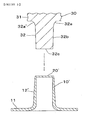
- Fig. 3 shows a state where the semifinished product (half-finished product) 10' which will become the button fastener 10 and a steel punch 30 for forming the semifinished product 10' to the button fastener 10 are arranged in the up-and-down direction.
- the punch 30 is placed above the semifinished product 10' concentrically.
- the semifinished product 10' is formed by drawing a metal plate, and comprises a base 11 (the same numeral is used as with the button fastener 10 as being substantially common) and an unfinished post 12' projecting from a center area of the base 11.
- the upper end face of the unfinished post 12' is closed by a disk-like closing part 20'.
- the unfinished post 12' does not include an upper end part with its diameter expanding radially outward as the upper end part 12a of the post 12 of the button fastener 10, and the outer diameter of the unfinished post 12' slightly decreases upward in a straight manner and the inner diameter thereof is almost constant. Therefore, the inner and outer diameters of the unfinished post 12' slightly decrease upward relative to the post 12.
- the punch 30 includes a punch base 31 as shown in a cutaway manner, which is connected to a up-and-down part of a press machine as not shown, and an almost columnar insert part 32 projecting downward from the punch base 31 with the outer diameter reduced, to be pressed into the unfinished post 12' of the semifinished product 10'.
- the insert part 32 includes an insert proximal part 32a defining a curved surface 32a' with the diameter reduced downward (the up-and-down direction of the punch is based on Fig. 3 ) from the punch base 31 in a curved manner, and an insert body 32b with the outer diameter slightly reduced downward from the insert proximal part 32a in a straight manner.
- the diameter of the bottom surface 32c of the insert part 32 is slightly larger than the inner diameter of the unfinished post 12', and the axial length of the insert part 32 is somewhat shorter than that of the unfinished post 12'.
- the punch 30 is lowered from the Fig. 3 state and then punches or cuts out, in a circular form, the closing part 20' closing the top face of the unfinished post 12' of the semifinished product 10'. Then the insert part 32 of the punch 30 moves down through the inside of the unfinished post 12' while pushing down the closing part 20', which has just been cut out, with the bottom surface 32c of the insert part 32.
- the step from the semifinished product 10' to the button fastener 10 is completed.
- the post 12 and the closing member 20 in the button fastener in Fig. 4 will also be referred to as the unfinished post 12' and the closing part 20' in the semifinished product 10'.
- the insert body 32b and the cut-out closing part 20' deform the unfinished post 12' so as to slightly expand the inner diameter of the unfinished post 12' radially outward.
- the inner diameter of the unfinished post 12' below the position, near the lower end of the unfinished post 12', at which the closing part 20' has been stopped as the closing member 20 of the button fastener 10 remains unchanged.
- the outer surface of the closing member 20 contacts and presses the inner surface of the unfinished post 12', and with a frictional force in between, the closing member 20 is fixed.
- the curved surface 32a' of the insert proximal part 32a expands the upper end part of the unfinished post 12' radially outward to form the upper end part 12a of the post 12.
- Fig. 5 is an illustrative longitudinal sectional view showing a state where a male snap button (hereinafter referred to also as simply “male snap") 40 has been fastened to a cloth 1 using the button fastener 10.
- the male snap 40 comprises a flange 41, and a protrusion 42 which protrudes from the flange 41 in its center area, the distal end of the protrusion 42 being closed.
- the protrusion 42 is engaged and disengaged with a recess of a female snap button as not shown.
- a post-fixing space 43 to receive, deform and fix the post 12 of the button fastener 10.
- the post 12 of the button fastener 10 goes into the post-fixing space 43 after piercing the cloth 1.
- a round cloth piece 1' is separated from the cloth 1.
- the cloth piece 1' can stay within the post 12 such as by catching on a distal part of the post 12 (a cloth piece which is not completely separated from the cloth 1 may also remain inside the post 12).
- Fig. 5 indicates a state where the cloth piece 1' has been captured in the post 12 through the top opening 13 for the sake of expediency. This cloth piece 1' staying in the post 12 and the deformed distal part of the post 12 cannot be seen through the bottom opening 14 by the presence of the closing member 20 in the vicinity of the lower end of the post 12.
- Fig. 6 is an illustrative longitudinal sectional view showing a state where a decorative button 50 has been fastened to a cloth 2 using the button fastener 10.
- the decorative button 50 comprises a flange 51, and a protrusion 52 which protrudes from the flange 51 in its center area, the distal end of the protrusion 52 being closed. Inside the the protrusion 52, there is defined a post-fixing space 53 to receive, deform and fix the post 12 of the button fastener 10.
- the post 12 of the button fastener 10 goes into the post-fixing space 53 after piercing the cloth 2.
- Fig. 7 shows a state where the top face or the closing part 70' has been punched in a petal form with five semicircular petal pieces arranged radially.
- Fig. 7 shows a state where the top face or the closing part 70' has been punched in a petal form with five semicircular petal pieces arranged radially.
- FIG. 7 shows the semifinished product 60' only through a punching process with a punch, which is not through, using a punch, a diameter expanding process to the unfinished post 62' and an expanding process to an upper end part of the unfinished post 62'.
- a punch the punch 30 in which a petal shaped bump is formed in the lower end part of the insert part 32 may be used.
- Fig. 8 is a partial bottom view, seen from below, showing a state where the closing part 70' which was punched in a petal form is fixed in the post 12 in the vicinity of its lower end as the closing member 70 of the button fastener 60.
- the petal-like closing member 70 can been seen through the bottom opening 64 from the back side of the cloth 1, 2, which could enhance the appearance.
- Fig. 9 shows a state where, after the semifinished product 10' has been finished to the button fastener 10 using the punch 30, the portion corresponding to the closing member 20 in the post 12 of the button fastener 10 is pressed radially inward and plastically deformed by a press member as not shown from, for instance, four points in the circumferential direction at the 90 degree interval so as to become depressed.
- the post 12 and the closing member 20 after being deformed are shown by the reference numerals 12", 20", respectively.
- Fig. 10 is a sectional view taken along the line A-A in Fig. 9 . With this additional modification, the strength to fix the closing member 20" increases with the diameter of the post 12 reduced in the vicinity of its lower end.
- the closing member 20 is deformed in an almost cross shape, and also in this case, the appearance seen from the back side improves.
- the closing member 20 is deformed in an almost cross shape, it is possible to form it in other shapes such as by increasing or decreasing pressing points on the post 12 in the circumferential direction.
- Fig. 11 is a partially cutaway perspective view of an eyelet 80 in accordance with an embodiment of another aspect of the invention.
- the eyelet 80 creates holes for passing air, water, etc. by being fastened to a cloth 3 (see Fig. 5 ).
- Fig. 12 is a longitudinal sectional view of the eyelet 80.
- the eyelet 80 is fabricated by first forming a semifinished product 80' (see Fig. 13 ) by drawing a plate material of copper alloy, and then finishing the semifinished product as described later.
- the eyelet 80 comprises a disk-like base 81 and a cylinder 82 projecting upward (the up-and-down direction of the eyelet is based on Fig. 14 ) from the base 81 concentrically therewith.
- the upper end face of the cylinder 82 is open as a top opening 83 and the lower end face thereof is open as a bottom opening 84.
- the thickness of the cylinder 82 becomes gradually thinner upward.
- the outer diameter of the cylinder 82 is almost constant, and the inner diameter thereof gradually slightly increases upward from a stepped part 85.
- a disk-like closing member 90 At a lower end side inside the cylinder 82, there is provided a disk-like closing member 90.
- the closing member 90 has, as an example, seven round holes 91 for passing air, water, etc.
- a stepped part 85 At a lower end side on the inner peripheral surface of the cylinder 82, there is formed a stepped part 85 at which the inner diameter is reduced downward in a stepped manner.
- the closing member 90 is disposed on the stepped part 85.
- the inner diameter of the stepped part 85 is slightly smaller than the outer diameter of the closing member 90, so that the closing member 90 is hindered from moving down by catching on the stepped part 85.
- the outer surface of the closing member 90 contacts and presses the inner surface of the cylinder 82, and with a frictional force in between, the closing member 90 in the cylinder 82 cannot be displaced upward as well.
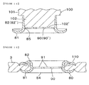
- Fig. 13 shows a state where the semifinished product (half-finished product) 80' which will become the eyelet 80 and a steel punch 100 for forming the semifinished product 80' to the eyelet 80 are arranged in the up-and-down direction.
- the punch 100 is placed above the semifinished product 80' concentrically.
- the semifinished product 80' is formed by drawing a metal plate, and comprises a base 81 (the same numeral is used as with the eyelet 80 as being substantially in common) and an unfinished cylinder 82' projecting from a center area of the base 81.
- the upper end face of the unfinished cylinder 82' is closed by a disk-like closing part 90'.
- the closing part 90' seven round holes 91 (the same reference numeral as with the closing member 90 is used as they are substantially the same) have been formed prior to the finishing with the punch 100.
- the outer diameter of the unfinished cylinder 82' slightly decreases upward in a straight manner and the inner diameter thereof is almost constant. Therefore, the inner and outer diameters of the unfinished cylinder 82' slightly decrease upward relative to the cylinder 82.
- the punch 100 includes a punch base 101 as shown in a cutaway manner, which is connected to a up-and-down part of a press machine as not shown, and an almost columnar insert part 102 projecting downward from the punch base 101 with the outer diameter reduced, to be pressed into the unfinished cylinder 82' of the semifinished product 80'.
- the outer diameter of the insert part 102 slightly reduces downward from the punch base 101 in a straight manner, and the diameter of the bottom surface 102' of the insert part 102 is slightly larger than the inner diameter of the unfinished cylinder 82'. Further, the axial length of the insert part 102 is somewhat shorter than that of the unfinished cylinder 82'.
- the punch 100 is lowered from the Fig. 13 state and then cuts out, in a circular form, the closing part 90' closing the top face of the unfinished cylinder 82' of the semifinished product 80'. Then the insert part 102 of the punch 100 moves down through the inside of the unfinished cylinder 82' while pushing down the closing part 90', which has just been cut out, with the bottom surface 102' of the insert part 102. By stopping the punch 102 at the Fig.
- the step from the semifinished product 80' to the eyelet 80 is completed.
- the cylinder 82 and the closing member 90 in the eyelet in Fig. 14 will also be referred to as the unfinished cylinder 82' and the closing part 90' in the semifinished product 80'.
- the insert part 102 moving down in the unfinished cylinder 82' the insert part 102 and the cut-out closing part 90' deform the unfinished cylinder 82' so as to slightly expand the inner diameter of the unfinished cylinder 82' radially outward.
- Fig. 15 is an illustrative longitudinal sectional view showing a state where the eyelet 80 has been fastened to a cloth 3.
- the reference numeral 110 indicates an annular washer, which is placed on the front side (upper surface side) of the cloth 3.
- the cylinder 82 of the eyelet 80 pierces the cloth 3 and then be curved radially outward in a C-letter form by an upper die as not shown to be received on the washer 110.
Landscapes
- Slide Fasteners, Snap Fasteners, And Hook Fasteners (AREA)
Abstract
Description
- The present invention relates to a button fastener, a method for forming a button fastener, an eyelet, and a method for forming an eyelet, and more specifically to a metallic button fastener with a cylindrical post to be passed through a cloth when a button such as a male snap button, a decorative button is fastened to the cloth, a method for forming such a button fastener, a metallic eyelet with a cylindrical part to be passed through a cloth to fasten the eyelet to the cloth, and a method for forming such an eyelet.
- As a male snap button (male snap) of a set of snap buttons as widely used in e.g. parts to be put together of clothes or a decorative button to be fixed to e.g. corners of a pocket of jeans, one has been known which includes a disk-like flange and a protrusion which protrudes from the flange in its center area, the distal end of the protrusion being closed. When such a male snap button or a decorative button becomes fastened to a cloth, a button fastener is generally used, which is formed by drawing one metal plate and includes a base and a post projecting from a center part of the base. That is, after the post of the button fastener has just pierced the cloth, the post is received in an inside space of the protrusion of the male snap button or decorative button and then deformed to be fixed in the space, and thereby the button as e.g. the male snap is fastened to the cloth. Such a button fastener is disclosed in
US Patent No. 3,351,987 , for instance. Also, as an eyelet to be fixed to a cloth for passing air, water, etc., one has been known which comprises an eyelet body including a base and a cylindrical part projecting from the base, and an perforated member which is attached to the cylindrical part of the eyelet body from the outside. - In the above post of the button fastener formed from one metal plate, the distal end face and the proximal end face of the post are open as a top opening and a bottom opening, respectively. Therefore, when a button is fastened to a cloth, a piece of the cloth, which has been separated from the cloth by the post piercing the cloth, would catch on a swaged distal side part of the post, or a piece or part of the cloth which is not completely separated from the cloth would remain inside the post. In these cases, it would be possible to see the cloth piece from the bottom side of the base of the button fastener through the bottom opening, which would make the appearance less attractive. To avoid this, an additional work to eject the cloth piece through the bottom opening is needed. Further, a swaged distal side part of the post can be seen from the bottom opening, which may also cause disfigurement. Although a button fastener with the proximal end of the post closed has been known, such a button fastener cannot be produced by drawing one metal plate, and it needs an assembling step to attach a separate member to the bottom opening of the post, which involves increasing product cost. Besides, the above-mentioned eyelet for passing air, water, etc. needs the perforated member other than the eyelet body, increasing the material cost for that.
-
- [Patent document 1]
US Patent No. 3,351,987 - An object of the invention as made in view of the above-mentioned problems is to provide a button fastener and a method for forming the button fastener with which a piece of a cloth, which may remain within a post of the button fastener as being completely or incompletely separated from the cloth during fastening a button to the cloth, or a swaged distal part of the post cannot be seen from the back side of the button fastener, enhancing the appearance as seen from the back side, and to provide a button fastener and a method for forming the button fastener which can be made from one metal plate cost advantageously.
- Another object of the invention is to provide an eyelet and a method for forming the eyelet for passing air, water, etc. which can be made cost advantageously.
- To solve the problems, according to the present invention, there is provided a button fastener made of metal for fastening a button to a cloth (the cloth includes fabric, textile, felt, nonwoven cloth, leather, resin sheet. Hereinafter the same shall apply), comprising a plate-like base and a cylindrical post projecting from a center area of the base, the distal end face of the post being open as a top opening, and the proximal end face of the post being open in the center area of the base as a bottom opening, wherein the button fastener includes a closing member which closes the inside of the post at a proximal side thereof.
- In the invention, the closing member is provided inside the post at a proximal side thereof, and the post has the top opening and the bottom opening. Therefore, a cloth piece, which can be separated from the cloth as the button is fastened to the cloth, or a swaged distal part of the post cannot be seen through the bottom opening.
- As a material of the button fastener, aluminum alloy, copper alloy, etc. are preferably cited, but other metals can be used.
- In an embodiment of the invention, the closing member is fixed in the post by the outer surface of the closing member contacting and pressing the inner surface of the post. In this case, the outer diameter of the closing member was made slightly larger than the inner diameter of a proximal side of the post, and the closing member is pushed into the post proximally. Thereby, the outer surface of the closing member contacts and presses the inner surface of the post, and with a frictional force in between, the closing member is fixed.
- In an embodiment of the invention, the post includes a stepped part on its inner surface at a proximal side with the inner diameter reduced proximally in a stepped manner, and the closing member is fixed on the stepped part. In this case, the closing member cannot move to the bottom opening inside the post by catching on the stepped part. When a semifinished product as described later is fabricated to the button fastener, a punch can be moved through the inside of the post toward its proximal end while slightly expanding the inner diameter of the post, and then stopped. The stepped part can be formed on the inner surface of the post at a proximal side at the boundary between the area where the inner diameter has been expanded and the area where the inner diameter remains unexpanded.
- In an embodiment of the invention, the closing member is a closing part which has been cut out of an unfinished post of a semifinished product which is fabricated to the button fastener, the closing part before being cut out closing the distal end face of the unfinished post. In this case, first the semifinished product is formed from one metal plate, and then the closing part which closes the distal end face of the unfinished post of the semifinished product is punched or cut out. The closing part as punched is used as the closing member of the button fastener, and the unfinished post is formed to the post of the button fastener. Therefore, materials for the closing member other than the metal plate are unnecessary.
- In the invention, the closing member may be formed in e.g. circular, polygonal, star, petal forms.
- In an embodiment of the invention, the portion of the post which corresponds to the closing member is depressed radially inward at two or more points in the circumferential direction. Thereby, the strength to fix the closing member can increase, and it would be possible to improve the appearance of the button fastener seen from the back side through the bottom opening such as by providing the post with four depressed portions in the circumferential direction at the 90 degree interval so as to form the closing member in an almost cross shape.
- According to another aspect of the present invention, there is provided a method for forming a button fastener made of metal for fastening a button to a cloth, the button fastener comprising a plate-like base and a cylindrical post projecting from a center area of the base, the distal end face of the post being open as a top opening, the proximal end face of the post being open in the center area of the base as a bottom opening, and the button fastener including a closing member which closes the inside of the post at a proximal side thereof, the method comprising the steps of: providing a semifinished product which comprises a plate-like base and an unfinished post projecting from a center area of the base, the unfinished post including a closing part which closes the distal end face of the unfinished post, and the proximal end face of the unfinished post being open in the center area of the base as a bottom opening; cutting out the closing part of the unfinished post of the semifinished product by a punch; and displacing the cut-out closing part with the punch through the inside of the unfinished post toward a proximal end to be used as the closing member.
- In the invention, to form the above-stated button fastener, firstly the semifinished product can be formed from one metal plate, the semifinished product including the unfinished post with the distal end face closed by the closing part. Next, the closing part of the semifinished product can be punched or cut out by the punch, and then the cut-out closing part is displaced by the punch through the inside of the unfinished post toward the proximal end to be the closing member. The unfinished post of the semifinished product is formed to the post of the button fastener by the punch cutting out and moving the closing part.
- In the invention, in the displacing step, the punch can displace the closing part while slightly expanding the inner diameter of the unfinished post. In this case, the punch moves proximally through the inside of the unfinished post of the semifinished product while slightly expanding the inner diameter of the unfinished post and then stops. Thereby, on the inner surface of the unfinished post at a proximal side thereof, at the boundary between the area where the inner diameter has been expanded and the area where the inner diameter remains unexpanded, a stepped part is formed. The closing part can be fixed on the stepped part.
- According to another aspect of the present invention, there is provided an eyelet made of metal to be fastened to a cloth, comprising a plate-like base and a cylinder projecting from a center area of the base, the distal end face of the cylinder being open as a top opening, and the proximal end face of the cylinder being open in the center area of the base as a bottom opening, wherein the eyelet includes a closing member which closes the inside of the cylinder at a proximal side thereof.
- In the invention, by punching the distal end face of the cylinder to be used as the closing member, it is possible to form the eyelet cost advantageously.
- In an embodiment of the invention, the closing member is fixed in the cylinder by the outer surface of the closing member contacting and pressing the inner surface of the cylinder. In this case, the outer diameter of the closing member was made slightly larger than the inner diameter of a proximal side of the cylinder, and the closing member is pushed into the cylinder proximally. Thereby, the outer surface of the closing member contacts and presses the inner surface of the cylinder, and with a frictional force in between, the closing member is fixed.
- In an embodiment of the invention, the cylinder includes a stepped part on its inner surface at a proximal side with the inner diameter reduced proximally in a stepped manner, and wherein the closing member is fixed on the stepped part. In this case, the closing member cannot move to the bottom opening inside the cylinder by catching on the stepped part. When a semifinished product as described later is fabricated to the eyelet, a punch can be moved through the inside of the cylinder toward its proximal end while slightly expanding the inner diameter of the cylinder, and then stopped. The stepped part can be formed on the inner surface of the cylinder at a proximal side at the boundary between the area where the inner diameter has been expanded and the area where the inner diameter remains unexpanded.
- In an embodiment of the invention, the closing member is a closing part which has been cut out of an unfinished cylinder of a semifinished product which is fabricated to the eyelet, the closing part before being cut out closing the distal end face of the unfinished cylinder.
In this case, first the semifinished product is formed from one metal plate, and then the closing part which closes the distal end face of the unfinished cylinder of the semifinished product is punched or cut out. The closing part as punched is used as the closing member of the eyelet, and the unfinished cylinder is formed to the cylinder of the eyelet. Therefore, materials for the closing member other than the metal plate is unnecessary. - In an embodiment of the invention, the closing member has a plurality of holes. Through the holes, air, water, etc. can flow in and out.
- According to another aspect of the present invention, there is provided a method for forming an eyelet made of metal to be fastened to a cloth, the eyelet comprising a plate-like base and a cylinder projecting from a center area of the base, the distal end face of the cylinder being open as a top opening, the proximal end face of the cylinder being open in the center area of the base as a bottom opening, and the eyelet including a closing member which closes the inside of the cylinder at a proximal side thereof, the method comprising the steps of: providing a semifinished product which comprises a plate-like base and an unfinished cylinder projecting from a center area of the base, the unfinished cylinder including a closing part which closes the distal end face of the unfinished cylinder, and the proximal end face of the unfinished cylinder being open in the center area of the base as a bottom opening; cutting out the closing part of the unfinished cylinder of the semifinished product by a punch; and displacing the cut-out closing part with the punch through the inside of the unfinished cylinder toward a proximal end to be used as the closing member.
- In the invention, to form the above-stated eyelet, firstly the semifinished product can be formed from one metal plate, the semifinished product including the unfinished cylinder with the distal end face closed by the closing part. Next, the closing part of the semifinished product can be punched or cut out by the punch, and then the cut-out closing part is displaced by the punch through the inside of the unfinished cylinder toward the proximal end to be the closing member. The unfinished cylinder of the semifinished product is formed to the cylinder of the eyelet by the punch cutting out and moving the closing part.
- In the invention, in the displacing step, the punch can displace the closing part while slightly expanding the inner diameter of the unfinished cylinder. In this case, the punch moves proximally through the inside of the unfinished cylinder of the semifinished product while slightly expanding the inner diameter of the unfinished cylinder and then stops. Thereby, on the inner surface of the unfinished cylinder at a proximal side thereof, at the boundary between the area where the inner diameter has been expanded and the area where the inner diameter remains unexpanded, a stepped part is formed. The closing part can be fixed on the stepped part.
- In the button fastener and the method for forming it, the closing member is provided inside the post at a proximal side thereof, and the post has the top opening and the bottom opening. Therefore, a cloth piece, which can stay within the post after being separated completely or incompletely from the cloth as the button is fastened to the cloth, or a swaged distal part of the post cannot be seen through the bottom opening, enhancing the appearance. An additional work to eject the cloth piece through the bottom opening of the button fastener is not needed. Further, the button fastener including the closing member can be formed from one metal plate effectively and cost advantageously.
- In the eyelet and the method for forming it, the closing member is provided inside the cylinder at a proximal side thereof, and the eyelet including the closing member can be formed from one metal plate effectively and cost advantageously.
-
-
Fig. 1 is a partially cutaway perspective view of a button fastener in accordance with an embodiment of the invention; -
Fig. 2 is a longitudinal sectional view of the button fastener inFig. 1 ; -
Fig. 3 is an illustrative longitudinal sectional view of a state where a semifinished product which will become the button fastener and a punch for use in a finishing step of the button fastener are arranged in the up-and-down direction; -
Fig. 4 is an illustrative longitudinal sectional view showing a state where the fabrication from the semifinished product to the button fastener has been completed; -
Fig. 5 is an illustrative longitudinal sectional view showing a state where a male snap button has been fastened to a cloth using the button fastener inFig. 1 etc.; -
Fig. 6 is an illustrative longitudinal sectional view showing a state where a decorative button has been fastened to a cloth using the button fastener inFig. 1 etc.; -
Fig. 7 is a cutaway perspective view of an upper half of the post expedientially showing another example of a punched form in the top face of the semifinished product; -
Fig. 8 is a partial bottom view, seen from below, of the button fastener as obtained from the semifinished product inFig. 7 ; -
Fig. 9 is a cutaway longitudinal sectional view showing an example further modifying the button fastener; -
Fig. 10 is a sectional view taken along the line A-A inFig. 9 ; -
Fig. 11 is a partially cutaway perspective view of an eyelet in accordance with an embodiment of another aspect of the invention; -
Fig. 12 is a longitudinal sectional view of the eyelet inFig. 11 ; -
Fig. 13 is an illustrative longitudinal sectional view showing a state where a semifinished product which will become the eyelet and a punch for use in a finishing step of the eyelet are arranged in the up-and-down direction; -
Fig. 14 is a longitudinal sectional view showing a state where the eyelet has been finished by the punch; and -
Fig. 15 is an illustrative longitudinal sectional view showing a state where the eyelet inFig. 11 etc. has been fastened to a cloth. - Hereinafter, preferred embodiments of the present invention will be described with reference to the drawings.
Fig. 1 is a partially cutaway perspective view of abutton fastener 10 in accordance with an embodiment of the invention.Fig. 2 is a longitudinal sectional view of thebutton fastener 10. Thebutton fastener 10 is fabricated by first forming a semifinished product 10' (seeFig. 3 ) and then finishing it. The semifinished product 10' is formed by drawing a plate material of copper alloy. The button fastener 1 comprises a disk-like base 11 and acylindrical post 12 projecting upward (the up-and-down direction of the button fastener is based onFig. 2 ) from thebase 11 concentrically therewith. The upper end face of thepost 12 is open as atop opening 13 and the lower end face thereof is open as abottom opening 14. The thickness of thepost 12 becomes gradually thinner upward, and anupper end part 12a of thepost 12 expands as it opens radially outward with the top (upper end) 12c sharpened. The outer diameter of thepost 12 except for theupper end part 12a is almost constant, and the inner diameter thereof gradually slightly increases upward from a steppedpart 15 as described later. At a lower end side inside thepost 12, there is provided a disk-like closing member 20. As described in detail later, a cloth piece 1', 2' can be produced by being separated from acloth 1, 2 when a male snap button 40 (seeFig. 5 ) or a decorative button 50 (seeFig. 6 ) is fastened to thecloth 1, 2 using thebutton fastener 10, and the closingmember 20 can hide the cloth piece 1', 2' from thebottom opening 13 even if it is left inside thepost 12. At a lower end side on the inner peripheral surface of thepost 12, there is formed a steppedpart 15 at which the inner diameter is reduced downward in a stepped manner. The closingmember 20 is disposed on the steppedpart 15. The inner diameter of the steppedpart 15 is slightly smaller than the outer diameter of the closingmember 20, so that the closingmember 20 is hindered from moving down by catching on the steppedpart 15. In addition, the outer surface of the closingmember 20 contacts and presses the inner surface of thepost 12 and, with a frictional force in between, the closingmember 20 in thepost 12 cannot be displaced upward as well. -
Fig. 3 shows a state where the semifinished product (half-finished product) 10' which will become thebutton fastener 10 and asteel punch 30 for forming the semifinished product 10' to thebutton fastener 10 are arranged in the up-and-down direction. Thepunch 30 is placed above the semifinished product 10' concentrically. The semifinished product 10' is formed by drawing a metal plate, and comprises a base 11 (the same numeral is used as with thebutton fastener 10 as being substantially common) and an unfinished post 12' projecting from a center area of thebase 11. The upper end face of the unfinished post 12' is closed by a disk-like closing part 20'. Further, the unfinished post 12' does not include an upper end part with its diameter expanding radially outward as theupper end part 12a of thepost 12 of thebutton fastener 10, and the outer diameter of the unfinished post 12' slightly decreases upward in a straight manner and the inner diameter thereof is almost constant. Therefore, the inner and outer diameters of the unfinished post 12' slightly decrease upward relative to thepost 12. - The
punch 30 includes apunch base 31 as shown in a cutaway manner, which is connected to a up-and-down part of a press machine as not shown, and an almostcolumnar insert part 32 projecting downward from thepunch base 31 with the outer diameter reduced, to be pressed into the unfinished post 12' of the semifinished product 10'. Theinsert part 32 includes an insertproximal part 32a defining acurved surface 32a' with the diameter reduced downward (the up-and-down direction of the punch is based onFig. 3 ) from thepunch base 31 in a curved manner, and aninsert body 32b with the outer diameter slightly reduced downward from the insertproximal part 32a in a straight manner. The diameter of thebottom surface 32c of theinsert part 32 is slightly larger than the inner diameter of the unfinished post 12', and the axial length of theinsert part 32 is somewhat shorter than that of the unfinished post 12'. - Next, a procedure to obtain the
button fastener 10 from the semifinished product 10' will be described as an embodiment of a method for forming the button fastener in accordance with the present invention. To finally fabricate the semifinished product 10' to thebutton fastener 10, thepunch 30 is lowered from theFig. 3 state and then punches or cuts out, in a circular form, the closing part 20' closing the top face of the unfinished post 12' of the semifinished product 10'. Then theinsert part 32 of thepunch 30 moves down through the inside of the unfinished post 12' while pushing down the closing part 20', which has just been cut out, with thebottom surface 32c of theinsert part 32. By stopping thepunch 30 at theFig. 4 state, the step from the semifinished product 10' to thebutton fastener 10 is completed. For the sake of a simple explanation, thepost 12 and the closingmember 20 in the button fastener inFig. 4 will also be referred to as the unfinished post 12' and the closing part 20' in the semifinished product 10'. During theinsert part 32 moving down in the unfinished post 12', theinsert body 32b and the cut-out closing part 20' deform the unfinished post 12' so as to slightly expand the inner diameter of the unfinished post 12' radially outward. In the meantime, the inner diameter of the unfinished post 12' below the position, near the lower end of the unfinished post 12', at which the closing part 20' has been stopped as the closingmember 20 of thebutton fastener 10 remains unchanged. Therefore, the inner surface area of the unfinished post 12' corresponding to the position of the closing part 20' stopped, there is formed the steppedpart 15 at which the inner diameter is reduced downward in a stepped manner. On the steppedpart 15, the outer surface of the closingmember 20 contacts and presses the inner surface of the unfinished post 12', and with a frictional force in between, the closingmember 20 is fixed. Further, at the final stage of lowering thepunch 30, thecurved surface 32a' of the insertproximal part 32a expands the upper end part of the unfinished post 12' radially outward to form theupper end part 12a of thepost 12. As described above, it is possible to do the finishing step from the semifinished product 10', which has been formed from one metal plate, to thebutton fastener 10 including the closingmember 20, and therefore another material for the closingmember 20 is unnecessary enhancing material efficiency. -
Fig. 5 is an illustrative longitudinal sectional view showing a state where a male snap button (hereinafter referred to also as simply "male snap") 40 has been fastened to a cloth 1 using thebutton fastener 10. Themale snap 40 comprises aflange 41, and a protrusion 42 which protrudes from theflange 41 in its center area, the distal end of the protrusion 42 being closed. The protrusion 42 is engaged and disengaged with a recess of a female snap button as not shown. Inside the protrusion 42, there is defined apost-fixing space 43 to receive, deform and fix thepost 12 of thebutton fastener 10. When themale snap 40 is fastened to the cloth 1 with thebutton fastener 10, thepost 12 of thebutton fastener 10 goes into thepost-fixing space 43 after piercing the cloth 1. By thepost 12 piercing the cloth 1, a round cloth piece 1' is separated from the cloth 1. When thepost 12 is deformed in thepost-fixing space 43, the cloth piece 1' can stay within thepost 12 such as by catching on a distal part of the post 12 (a cloth piece which is not completely separated from the cloth 1 may also remain inside the post 12).Fig. 5 (andFig. 6 ) indicates a state where the cloth piece 1' has been captured in thepost 12 through thetop opening 13 for the sake of expediency. This cloth piece 1' staying in thepost 12 and the deformed distal part of thepost 12 cannot be seen through thebottom opening 14 by the presence of the closingmember 20 in the vicinity of the lower end of thepost 12. -
Fig. 6 is an illustrative longitudinal sectional view showing a state where adecorative button 50 has been fastened to acloth 2 using thebutton fastener 10. Thedecorative button 50 comprises aflange 51, and aprotrusion 52 which protrudes from theflange 51 in its center area, the distal end of theprotrusion 52 being closed. Inside the theprotrusion 52, there is defined apost-fixing space 53 to receive, deform and fix thepost 12 of thebutton fastener 10. When thedecorative button 50 is fastened to thecloth 2 with thebutton fastener 10, thepost 12 of thebutton fastener 10 goes into thepost-fixing space 53 after piercing thecloth 2. By thepost 12 piercing thecloth 2, a round cloth piece 2' is separated from thecloth 2. When thepost 12 is deformed in thepost-fixing space 53, the cloth piece 2' can stay within the post 12 (a cloth piece which is not completely separated from thecloth 2 may also remain inside the post 12). This cloth piece 2' staying in thepost 12 and the deformed distal part of thepost 12 cannot be seen through thebottom opening 14 by the presence of the closingmember 20 in the vicinity of the lower end of thepost 12. - In the embodiments, an example is cited wherein the top face or the closing part 20' of the semifinished product 10' is punched by the
punch 30 in a circular form to make the closingmember 20 circular, but the present invention is not limited thereto. In the invention, it is possible to punch the top face of the semifinished product in a form other than a circular form so as to form the closing member of the button fastener in a form other than a circular form. For example,Fig. 7 shows a state where the top face or the closing part 70' has been punched in a petal form with five semicircular petal pieces arranged radially. For the sake of a simple explanation,Fig. 7 shows the semifinished product 60' only through a punching process with a punch, which is not through, using a punch, a diameter expanding process to the unfinished post 62' and an expanding process to an upper end part of the unfinished post 62'. Although not shown, as a punch, thepunch 30 in which a petal shaped bump is formed in the lower end part of theinsert part 32 may be used.Fig. 8 is a partial bottom view, seen from below, showing a state where the closing part 70' which was punched in a petal form is fixed in thepost 12 in the vicinity of its lower end as the closingmember 70 of thebutton fastener 60. In a case where themale snap 40 or thedecorative button 50 is fastened to thecloth 1 or 2 using thebutton fastener 60, the petal-like closing member 70 can been seen through thebottom opening 64 from the back side of thecloth 1, 2, which could enhance the appearance. -
Fig. 9 shows a state where, after the semifinished product 10' has been finished to thebutton fastener 10 using thepunch 30, the portion corresponding to the closingmember 20 in thepost 12 of thebutton fastener 10 is pressed radially inward and plastically deformed by a press member as not shown from, for instance, four points in the circumferential direction at the 90 degree interval so as to become depressed. Thepost 12 and the closingmember 20 after being deformed are shown by thereference numerals 12", 20", respectively.Fig. 10 is a sectional view taken along the line A-A inFig. 9 . With this additional modification, the strength to fix the closingmember 20" increases with the diameter of thepost 12 reduced in the vicinity of its lower end. In addition, the closingmember 20 is deformed in an almost cross shape, and also in this case, the appearance seen from the back side improves. Although, in the example, the closingmember 20 is deformed in an almost cross shape, it is possible to form it in other shapes such as by increasing or decreasing pressing points on thepost 12 in the circumferential direction. -
Fig. 11 is a partially cutaway perspective view of aneyelet 80 in accordance with an embodiment of another aspect of the invention. Theeyelet 80 creates holes for passing air, water, etc. by being fastened to a cloth 3 (seeFig. 5 ).Fig. 12 is a longitudinal sectional view of theeyelet 80. Theeyelet 80 is fabricated by first forming a semifinished product 80' (seeFig. 13 ) by drawing a plate material of copper alloy, and then finishing the semifinished product as described later. Theeyelet 80 comprises a disk-like base 81 and acylinder 82 projecting upward (the up-and-down direction of the eyelet is based onFig. 14 ) from thebase 81 concentrically therewith. The upper end face of thecylinder 82 is open as atop opening 83 and the lower end face thereof is open as abottom opening 84. The thickness of thecylinder 82 becomes gradually thinner upward. The outer diameter of thecylinder 82 is almost constant, and the inner diameter thereof gradually slightly increases upward from a steppedpart 85. At a lower end side inside thecylinder 82, there is provided a disk-like closing member 90. The closingmember 90 has, as an example, sevenround holes 91 for passing air, water, etc. At a lower end side on the inner peripheral surface of thecylinder 82, there is formed a steppedpart 85 at which the inner diameter is reduced downward in a stepped manner. The closingmember 90 is disposed on the steppedpart 85. The inner diameter of the steppedpart 85 is slightly smaller than the outer diameter of the closingmember 90, so that the closingmember 90 is hindered from moving down by catching on the steppedpart 85. In addition, the outer surface of the closingmember 90 contacts and presses the inner surface of thecylinder 82, and with a frictional force in between, the closingmember 90 in thecylinder 82 cannot be displaced upward as well. -
Fig. 13 shows a state where the semifinished product (half-finished product) 80' which will become theeyelet 80 and asteel punch 100 for forming the semifinished product 80' to theeyelet 80 are arranged in the up-and-down direction. Thepunch 100 is placed above the semifinished product 80' concentrically. The semifinished product 80' is formed by drawing a metal plate, and comprises a base 81 (the same numeral is used as with theeyelet 80 as being substantially in common) and an unfinished cylinder 82' projecting from a center area of thebase 81. The upper end face of the unfinished cylinder 82' is closed by a disk-like closing part 90'. In the closing part 90', seven round holes 91 (the same reference numeral as with the closingmember 90 is used as they are substantially the same) have been formed prior to the finishing with thepunch 100. The outer diameter of the unfinished cylinder 82' slightly decreases upward in a straight manner and the inner diameter thereof is almost constant. Therefore, the inner and outer diameters of the unfinished cylinder 82' slightly decrease upward relative to thecylinder 82. - The
punch 100 includes apunch base 101 as shown in a cutaway manner, which is connected to a up-and-down part of a press machine as not shown, and an almostcolumnar insert part 102 projecting downward from thepunch base 101 with the outer diameter reduced, to be pressed into the unfinished cylinder 82' of the semifinished product 80'. The outer diameter of theinsert part 102 slightly reduces downward from thepunch base 101 in a straight manner, and the diameter of the bottom surface 102' of theinsert part 102 is slightly larger than the inner diameter of the unfinished cylinder 82'. Further, the axial length of theinsert part 102 is somewhat shorter than that of the unfinished cylinder 82'. - Next, a procedure to obtain the
eyelet 80 from the semifinished product 80' will be described as an embodiment of a method for forming the eyelet in accordance with the present invention. To finally fabricate the semifinished product 80' to theeyelet 80, thepunch 100 is lowered from theFig. 13 state and then cuts out, in a circular form, the closing part 90' closing the top face of the unfinished cylinder 82' of the semifinished product 80'. Then theinsert part 102 of thepunch 100 moves down through the inside of the unfinished cylinder 82' while pushing down the closing part 90', which has just been cut out, with the bottom surface 102' of theinsert part 102. By stopping thepunch 102 at theFig. 14 state at which thepunch base 101 contacts the upper end of the unfinished cylinder 82', the step from the semifinished product 80' to theeyelet 80 is completed. For the sake of a simple explanation, thecylinder 82 and the closingmember 90 in the eyelet inFig. 14 will also be referred to as the unfinished cylinder 82' and the closing part 90' in the semifinished product 80'. During theinsert part 102 moving down in the unfinished cylinder 82', theinsert part 102 and the cut-out closing part 90' deform the unfinished cylinder 82' so as to slightly expand the inner diameter of the unfinished cylinder 82' radially outward. In the meantime, the inner diameter of the unfinished cylinder 82' below the position, near the lower end of the unfinished cylinder 82', at which the closing part 90' has been stopped as the closingmember 90 of theeyelet 80 remains unchanged. Therefore, the inner surface area of the unfinished cylinder 82' corresponding to the position of the closingmember 90 stopped, there is formed the steppedpart 85 at which the inner diameter is reduced downward in a stepped manner. On the steppedpart 85, the outer surface of the closingmember 90 contacts and presses the inner surface of the unfinished cylinder 82', and with a frictional force in between, the closingmember 90 is fixed. As described above, it is possible to do the finishing step from the semifinished product 80', which has been formed from one metal plate, to theeyelet 80 including the closingmember 90, and therefore another material for the closingmember 90 is unnecessary enhancing material efficiency. -
Fig. 15 is an illustrative longitudinal sectional view showing a state where theeyelet 80 has been fastened to acloth 3. InFig. 15 , thereference numeral 110 indicates an annular washer, which is placed on the front side (upper surface side) of thecloth 3. When theeyelet 80 is fastened to thecloth 3, thecylinder 82 of theeyelet 80 pierces thecloth 3 and then be curved radially outward in a C-letter form by an upper die as not shown to be received on thewasher 110. -
- 1, 2, 3
- cloth
- 1', 2'
- cloth piece
- 10
- button fastener
- 10', 60'
- semifinished product
- 11
- base
- 12, 12", 62
- post
- 12', 62'
- unfinished post
- 13
- top opening
- 14, 64
- bottom opening
- 15
- stepped part
- 20, 20", 70
- closing member
- 20', 70'
- closing part
- 30, 100
- punch
- 40
- male snap button
- 50
- decorative snap button
- 80
- eyelet
- 80'
- semifinished product 80'
- 81
- base
- 82
- cylinder
- 82'
- unfinished cylinder 82'
- 83
- top opening
- 84
- bottom opening
- 85
- stepped part
- 90
- closing member
- 90'
- closing part
- 91
- hole
Claims (14)
- A button fastener (10, 60) made of metal for fastening a button (40, 50) to a cloth (1, 2), comprising a plate-like base (11, 61) and a cylindrical post (12, 62) projecting from a center area of the base (11, 61), the distal end face of the post (12, 62) being open as a top opening (13), and the proximal end face of the post (12, 62) being open in the center area of the base (11, 61) as a bottom opening (14, 64),
wherein the button fastener (10, 60) includes a closing member (20, 70) which closes the inside of the post (12, 62) at a proximal side thereof. - The button fastener according to claim 1, wherein the closing member (20, 70) is fixed in the post (12, 62) by the outer surface of the closing member (20, 70) contacting and pressing the inner surface of the post (12, 62).
- The button fastener according to claim 1, wherein the post (12, 62) includes a stepped part (15) on its inner surface at a proximal side with the inner diameter reduced proximally in a stepped manner, and wherein the closing member (20, 70) is fixed on the stepped part (15).
- The button fastener according to any one of claims 1 to 3, wherein the closing member (20, 70) is a closing part (20', 70') which has been cut out of an unfinished post (12', 62') of a semifinished product (10', 60') which is fabricated to the button fastener (10, 60), the closing part (20', 70') before being cut out closing the distal end face of the unfinished post (12', 62').
- The button fastener according to any one of claims 1 to 4, wherein the portion of the post (12") which corresponds to the closing member (20") is depressed radially inward at two or more points in the circumferential direction.
- A method for forming a button fastener (10, 60) made of metal for fastening a button (40, 50) to a cloth (1, 2), the button fastener (10, 60) comprising a plate-like base (11, 61) and a cylindrical post (12, 62) projecting from a center area of the base (11, 61), the distal end face of the post (12, 62) being open as a top opening (13), the proximal end face of the post (12, 62) being open in the center area of the base (11, 61) as a bottom opening (14, 64), and the button fastener (10, 60) including a closing member (20, 70) which closes the inside of the post (12, 62) at a proximal side thereof, the method comprising the steps of:providing a semifinished product (10', 60') which comprises a plate-like base (11, 61) and an unfinished post (12', 62') projecting from a center area of the base (11, 61), the unfinished post (12', 62') including a closing part (20', 70') which closes the distal end face of the unfinished post (12', 62'), and the proximal end face of the unfinished post (12', 62') being open in the center area of the base (11, 61) as a bottom opening (14, 64);cutting out the closing part (20', 70') of the unfinished post (12', 62') of the semifinished product (10', 60') by a punch (30); anddisplacing the cut-out closing part (20', 70') with the punch (30) through the inside of the unfinished post (12', 62') toward a proximal end to be used as the closing member (20, 70).
- The method according to claim 6 wherein, in the displacing step, the punch (30) displaces the closing part (20', 70') while slightly expanding the inner diameter of the unfinished post (12', 62').
- An eyelet (80) made of metal to be fastened to a cloth (3), comprising a plate-like base (81) and a cylinder (82) projecting from a center area of the base (81), the distal end face of the cylinder (82) being open as a top opening (83), and the proximal end face of the cylinder (82) being open in the center area of the base (81) as a bottom opening (84),
wherein the eyelet (80) includes a closing member (90) which closes the inside of the cylinder (82) at a proximal side thereof. - The eyelet according to claim 8, wherein the closing member (90) is fixed in the cylinder (82) by the outer surface of the closing member (90) contacting and pressing the inner surface of the cylinder (82).
- The eyelet according to claim 8 or 9, wherein the cylinder (82) includes a stepped part (85) on its inner surface at a proximal side with the inner diameter reduced proximally in a stepped manner, and wherein the closing member (90) is fixed on the stepped part (85).
- The eyelet according to any one of claims 8 to 10, wherein the closing member (90) is a closing part (90') which has been cut out of an unfinished cylinder (82') of a semifinished product (80') which is fabricated to the eyelet (80), the closing part (90') before being cut out closing the distal end face of the unfinished cylinder (82').
- The eyelet according to any one of claims 8 to 11, wherein the closing member (90) has a plurality of holes (91).
- A method for forming an eyelet (80) made of metal to be fastened to a cloth (3), the eyelet (80) comprising a plate-like base (81) and a cylinder (82) projecting from a center area of the base (81), the distal end face of the cylinder (82) being open as a top opening (83), the proximal end face of the cylinder (82) being open in the center area of the base (81) as a bottom opening (84), and the eyelet (80) including a closing member (90) which closes the inside of the cylinder (82) at a proximal side thereof, the method comprising the steps of:providing a semifinished product (80') which comprises a plate-like base (81) and an unfinished cylinder (82') projecting from a center area of the base (81), the unfinished cylinder (82') including a closing part (90') which closes the distal end face of the unfinished cylinder (82'), and the proximal end face of the unfinished cylinder (82') being open in the center area of the base as a bottom opening (84);cutting out the closing part (90') of the unfinished cylinder (82') of the semifinished product (80') by a punch (100); anddisplacing the cut-out closing part (90') with the punch (100) through the inside of the unfinished cylinder (82') toward a proximal end to be used as the closing member (90).
- The method according to claim 13 wherein, in the displacing step, the punch (100) displaces the closing part (90') while slightly expanding the inner diameter of the unfinished cylinder (82').
Priority Applications (2)
| Application Number | Priority Date | Filing Date | Title |
|---|---|---|---|
| PL10846531T PL2540186T3 (en) | 2010-02-26 | 2010-02-26 | Button fixing member and method for forming button fixing member, eyelet member and method for forming eyelet member |
| HUE10846531A HUE045172T2 (en) | 2010-02-26 | 2010-02-26 | Button fixing member and method for forming button fixing member, eyelet member and method for forming eyelet member |
Applications Claiming Priority (1)
| Application Number | Priority Date | Filing Date | Title |
|---|---|---|---|
| PCT/JP2010/053100 WO2011104867A1 (en) | 2010-02-26 | 2010-02-26 | Button fixing member and method for forming button fixing member, eyelet member and method for forming eyelet member |
Publications (3)
| Publication Number | Publication Date |
|---|---|
| EP2540186A1 true EP2540186A1 (en) | 2013-01-02 |
| EP2540186A4 EP2540186A4 (en) | 2017-11-01 |
| EP2540186B1 EP2540186B1 (en) | 2019-05-08 |
Family
ID=44506310
Family Applications (1)
| Application Number | Title | Priority Date | Filing Date |
|---|---|---|---|
| EP10846531.1A Active EP2540186B1 (en) | 2010-02-26 | 2010-02-26 | Button fixing member and method for forming button fixing member, eyelet member and method for forming eyelet member |
Country Status (7)
| Country | Link |
|---|---|
| US (1) | US9049904B2 (en) |
| EP (1) | EP2540186B1 (en) |
| JP (1) | JP5615896B2 (en) |
| CN (1) | CN102858198B (en) |
| HU (1) | HUE045172T2 (en) |
| PL (1) | PL2540186T3 (en) |
| WO (1) | WO2011104867A1 (en) |
Families Citing this family (8)
| Publication number | Priority date | Publication date | Assignee | Title |
|---|---|---|---|---|
| ITBO20120426A1 (en) | 2012-08-02 | 2014-02-03 | Riri Sa | REINFORCEMENT EYE FOR A HOLE |
| JP6054228B2 (en) * | 2013-03-29 | 2016-12-27 | Ykk株式会社 | Eyelet mounting device |
| US9375057B2 (en) | 2014-03-14 | 2016-06-28 | Annalee Oakley | Snap button and method of use |
| US10897965B2 (en) * | 2016-03-30 | 2021-01-26 | Ykk Corporation | Snap button and male body forming method |
| USD846279S1 (en) | 2016-11-01 | 2019-04-23 | Zambrini, Llc | Receptacle |
| USD831936S1 (en) * | 2017-07-14 | 2018-10-30 | Gladd Unique Jewels | Connection structure for a garment styler |
| EP3659458B1 (en) * | 2018-11-30 | 2022-11-23 | Carmo Holding ApS | Metal eyelet |
| CN119281967B (en) * | 2024-12-12 | 2025-03-11 | 福建伯顿服饰有限公司 | Button detains cap blanking former |
Family Cites Families (20)
| Publication number | Priority date | Publication date | Assignee | Title |
|---|---|---|---|---|
| US660558A (en) * | 1900-05-11 | 1900-10-30 | Daniel A Carpenter | Button. |
| US1876853A (en) * | 1931-06-18 | 1932-09-13 | Patent Button Co | Shell button |
| US1862076A (en) * | 1931-09-02 | 1932-06-07 | Patent Button Co | Button |
| US1841578A (en) * | 1931-09-05 | 1932-01-19 | Scovill Manufacturing Co | Thick-edge tack-fastened button |
| US1876854A (en) * | 1932-03-17 | 1932-09-13 | Patent Button Co | Button |
| US2932073A (en) * | 1956-03-26 | 1960-04-12 | United Carr Fastener Corp | Fastening device |
| US3351987A (en) | 1965-10-22 | 1967-11-14 | Scovill Manufacturing Co | Post for attaching snap fastener stud elements |
| US4180899A (en) * | 1977-08-09 | 1980-01-01 | Mikosinski Ronald M | Method of assembling a fastener |
| JPS55145911U (en) * | 1979-04-05 | 1980-10-20 | ||
| JPS5839722B2 (en) | 1979-04-27 | 1983-09-01 | 正則 谷口 | Chain conveyor recycling method |
| JPS5957108A (en) | 1982-09-27 | 1984-04-02 | Toshiba Corp | System for judging damage of paper |
| JPS5957108U (en) * | 1982-10-09 | 1984-04-14 | モリト株式会社 | Net eyelet parts |
| JPS61202214U (en) | 1985-06-07 | 1986-12-18 | ||
| JPS62123108A (en) | 1985-11-21 | 1987-06-04 | Kanebo Ltd | Hair tonic cosmetic |
| JPS62123108U (en) * | 1986-01-27 | 1987-08-05 | ||
| JPH0811083B2 (en) | 1987-04-18 | 1996-02-07 | 精 武田 | Mating body for snap fastener |
| JP3046971B2 (en) * | 1992-11-30 | 2000-05-29 | ワイケイケイ株式会社 | Female body of snap button and crimping type |
| IT1313772B1 (en) * | 1999-10-06 | 2002-09-17 | Gaetano Raccosta | IMPROVED COUNTERMASK FOR AUTOMATIC AND AUTOMATIC BUTTON EQUIPPED WITH THIS COUNTERMASK. |
| JP2003310309A (en) * | 2002-04-18 | 2003-11-05 | Sogeisha:Kk | Trim head of hook and hook with the same |
| JP2005204911A (en) | 2004-01-22 | 2005-08-04 | Ykk Corp | button |
-
2010
- 2010-02-26 JP JP2012501595A patent/JP5615896B2/en not_active Expired - Fee Related
- 2010-02-26 HU HUE10846531A patent/HUE045172T2/en unknown
- 2010-02-26 US US13/581,359 patent/US9049904B2/en active Active
- 2010-02-26 CN CN201080066474.6A patent/CN102858198B/en not_active Expired - Fee Related
- 2010-02-26 PL PL10846531T patent/PL2540186T3/en unknown
- 2010-02-26 WO PCT/JP2010/053100 patent/WO2011104867A1/en not_active Ceased
- 2010-02-26 EP EP10846531.1A patent/EP2540186B1/en active Active
Non-Patent Citations (1)
| Title |
|---|
| See references of WO2011104867A1 * |
Also Published As
| Publication number | Publication date |
|---|---|
| PL2540186T3 (en) | 2019-10-31 |
| HUE045172T2 (en) | 2019-12-30 |
| US9049904B2 (en) | 2015-06-09 |
| CN102858198A (en) | 2013-01-02 |
| JPWO2011104867A1 (en) | 2013-06-17 |
| JP5615896B2 (en) | 2014-10-29 |
| EP2540186B1 (en) | 2019-05-08 |
| EP2540186A4 (en) | 2017-11-01 |
| WO2011104867A1 (en) | 2011-09-01 |
| US20120317760A1 (en) | 2012-12-20 |
| CN102858198B (en) | 2015-06-17 |
Similar Documents
| Publication | Publication Date | Title |
|---|---|---|
| EP2540186B1 (en) | Button fixing member and method for forming button fixing member, eyelet member and method for forming eyelet member | |
| CN102948946B (en) | Puncher pin for installing buttons, device for installing buttons and method for installing buttons | |
| EP2514334A1 (en) | Button fastener and button structure | |
| EP3216363B1 (en) | Die-cast snap button | |
| JP2014133261A (en) | Molding method of press part, manufacturing method of press part and molding metal mold of press part | |
| JP5313359B2 (en) | Button mounting method, button mounting system, and upper mold for button mounting | |
| EP2524612B1 (en) | Member for attaching button and button | |
| EP2417864A1 (en) | Button-mounting member | |
| CN107920633B (en) | Snap fastener | |
| US20120298308A1 (en) | Upper Die for Fastening Button | |
| JP2014108457A (en) | Method of manufacturing bracket, and mold for use in the same | |
| JP5859030B2 (en) | Button mounting device and button holding die | |
| EP2052638A2 (en) | Button | |
| JPWO2012004870A1 (en) | Decorative part and method for forming the same | |
| JP5731589B2 (en) | Button mounting member forming method | |
| US3320644A (en) | Tack-fastened button | |
| JP5863912B2 (en) | Eyelet member forming method | |
| JP6170572B2 (en) | Button stop | |
| JP2010058142A (en) | Method for press-forming cylindrical component with sharp edge | |
| WO2008074964A1 (en) | Method of joining metal parts | |
| US2083589A (en) | Method of making attaching members | |
| US2932073A (en) | Fastening device | |
| US3675817A (en) | Fastening device | |
| US1765055A (en) | Tack-attached sheet-metal button | |
| US3208313A (en) | Method of making a cuff link action component |
Legal Events
| Date | Code | Title | Description |
|---|---|---|---|
| PUAI | Public reference made under article 153(3) epc to a published international application that has entered the european phase |
Free format text: ORIGINAL CODE: 0009012 |
|
| 17P | Request for examination filed |
Effective date: 20120913 |
|
| AK | Designated contracting states |
Kind code of ref document: A1 Designated state(s): AT BE BG CH CY CZ DE DK EE ES FI FR GB GR HR HU IE IS IT LI LT LU LV MC MK MT NL NO PL PT RO SE SI SK SM TR |
|
| DAX | Request for extension of the european patent (deleted) | ||
| RA4 | Supplementary search report drawn up and despatched (corrected) |
Effective date: 20171002 |
|
| RIC1 | Information provided on ipc code assigned before grant |
Ipc: A44B 99/00 20100101ALI20170926BHEP Ipc: A44B 17/00 20060101AFI20170926BHEP |
|
| REG | Reference to a national code |
Ref country code: DE Ref legal event code: R079 Ref document number: 602010058842 Country of ref document: DE Free format text: PREVIOUS MAIN CLASS: A44B0017000000 Ipc: A44B0001440000 |
|
| RIC1 | Information provided on ipc code assigned before grant |
Ipc: A44B 1/44 20060101AFI20181025BHEP Ipc: A44B 17/00 20060101ALI20181025BHEP Ipc: A44B 13/00 20060101ALI20181025BHEP |
|
| GRAP | Despatch of communication of intention to grant a patent |
Free format text: ORIGINAL CODE: EPIDOSNIGR1 |
|
| STAA | Information on the status of an ep patent application or granted ep patent |
Free format text: STATUS: GRANT OF PATENT IS INTENDED |
|
| INTG | Intention to grant announced |
Effective date: 20181203 |
|
| GRAS | Grant fee paid |
Free format text: ORIGINAL CODE: EPIDOSNIGR3 |
|
| GRAA | (expected) grant |
Free format text: ORIGINAL CODE: 0009210 |
|
| STAA | Information on the status of an ep patent application or granted ep patent |
Free format text: STATUS: THE PATENT HAS BEEN GRANTED |
|
| AK | Designated contracting states |
Kind code of ref document: B1 Designated state(s): AT BE BG CH CY CZ DE DK EE ES FI FR GB GR HR HU IE IS IT LI LT LU LV MC MK MT NL NO PL PT RO SE SI SK SM TR |
|
| REG | Reference to a national code |
Ref country code: GB Ref legal event code: FG4D |
|
| REG | Reference to a national code |
Ref country code: CH Ref legal event code: EP Ref country code: AT Ref legal event code: REF Ref document number: 1128806 Country of ref document: AT Kind code of ref document: T Effective date: 20190515 |
|
| REG | Reference to a national code |
Ref country code: DE Ref legal event code: R096 Ref document number: 602010058842 Country of ref document: DE |
|
| REG | Reference to a national code |
Ref country code: IE Ref legal event code: FG4D |
|
| REG | Reference to a national code |
Ref country code: NL Ref legal event code: MP Effective date: 20190508 |
|
| REG | Reference to a national code |
Ref country code: LT Ref legal event code: MG4D |
|
| PG25 | Lapsed in a contracting state [announced via postgrant information from national office to epo] |
Ref country code: NO Free format text: LAPSE BECAUSE OF FAILURE TO SUBMIT A TRANSLATION OF THE DESCRIPTION OR TO PAY THE FEE WITHIN THE PRESCRIBED TIME-LIMIT Effective date: 20190808 Ref country code: ES Free format text: LAPSE BECAUSE OF FAILURE TO SUBMIT A TRANSLATION OF THE DESCRIPTION OR TO PAY THE FEE WITHIN THE PRESCRIBED TIME-LIMIT Effective date: 20190508 Ref country code: LT Free format text: LAPSE BECAUSE OF FAILURE TO SUBMIT A TRANSLATION OF THE DESCRIPTION OR TO PAY THE FEE WITHIN THE PRESCRIBED TIME-LIMIT Effective date: 20190508 Ref country code: NL Free format text: LAPSE BECAUSE OF FAILURE TO SUBMIT A TRANSLATION OF THE DESCRIPTION OR TO PAY THE FEE WITHIN THE PRESCRIBED TIME-LIMIT Effective date: 20190508 Ref country code: HR Free format text: LAPSE BECAUSE OF FAILURE TO SUBMIT A TRANSLATION OF THE DESCRIPTION OR TO PAY THE FEE WITHIN THE PRESCRIBED TIME-LIMIT Effective date: 20190508 Ref country code: PT Free format text: LAPSE BECAUSE OF FAILURE TO SUBMIT A TRANSLATION OF THE DESCRIPTION OR TO PAY THE FEE WITHIN THE PRESCRIBED TIME-LIMIT Effective date: 20190908 Ref country code: SE Free format text: LAPSE BECAUSE OF FAILURE TO SUBMIT A TRANSLATION OF THE DESCRIPTION OR TO PAY THE FEE WITHIN THE PRESCRIBED TIME-LIMIT Effective date: 20190508 Ref country code: FI Free format text: LAPSE BECAUSE OF FAILURE TO SUBMIT A TRANSLATION OF THE DESCRIPTION OR TO PAY THE FEE WITHIN THE PRESCRIBED TIME-LIMIT Effective date: 20190508 |
|
| PG25 | Lapsed in a contracting state [announced via postgrant information from national office to epo] |
Ref country code: LV Free format text: LAPSE BECAUSE OF FAILURE TO SUBMIT A TRANSLATION OF THE DESCRIPTION OR TO PAY THE FEE WITHIN THE PRESCRIBED TIME-LIMIT Effective date: 20190508 Ref country code: GR Free format text: LAPSE BECAUSE OF FAILURE TO SUBMIT A TRANSLATION OF THE DESCRIPTION OR TO PAY THE FEE WITHIN THE PRESCRIBED TIME-LIMIT Effective date: 20190809 Ref country code: BG Free format text: LAPSE BECAUSE OF FAILURE TO SUBMIT A TRANSLATION OF THE DESCRIPTION OR TO PAY THE FEE WITHIN THE PRESCRIBED TIME-LIMIT Effective date: 20190808 |
|
| REG | Reference to a national code |
Ref country code: AT Ref legal event code: MK05 Ref document number: 1128806 Country of ref document: AT Kind code of ref document: T Effective date: 20190508 |
|
| REG | Reference to a national code |
Ref country code: HU Ref legal event code: AG4A Ref document number: E045172 Country of ref document: HU |
|
| PG25 | Lapsed in a contracting state [announced via postgrant information from national office to epo] |
Ref country code: CZ Free format text: LAPSE BECAUSE OF FAILURE TO SUBMIT A TRANSLATION OF THE DESCRIPTION OR TO PAY THE FEE WITHIN THE PRESCRIBED TIME-LIMIT Effective date: 20190508 Ref country code: SK Free format text: LAPSE BECAUSE OF FAILURE TO SUBMIT A TRANSLATION OF THE DESCRIPTION OR TO PAY THE FEE WITHIN THE PRESCRIBED TIME-LIMIT Effective date: 20190508 Ref country code: DK Free format text: LAPSE BECAUSE OF FAILURE TO SUBMIT A TRANSLATION OF THE DESCRIPTION OR TO PAY THE FEE WITHIN THE PRESCRIBED TIME-LIMIT Effective date: 20190508 Ref country code: RO Free format text: LAPSE BECAUSE OF FAILURE TO SUBMIT A TRANSLATION OF THE DESCRIPTION OR TO PAY THE FEE WITHIN THE PRESCRIBED TIME-LIMIT Effective date: 20190508 Ref country code: AT Free format text: LAPSE BECAUSE OF FAILURE TO SUBMIT A TRANSLATION OF THE DESCRIPTION OR TO PAY THE FEE WITHIN THE PRESCRIBED TIME-LIMIT Effective date: 20190508 Ref country code: EE Free format text: LAPSE BECAUSE OF FAILURE TO SUBMIT A TRANSLATION OF THE DESCRIPTION OR TO PAY THE FEE WITHIN THE PRESCRIBED TIME-LIMIT Effective date: 20190508 |
|
| REG | Reference to a national code |
Ref country code: DE Ref legal event code: R097 Ref document number: 602010058842 Country of ref document: DE |
|
| PG25 | Lapsed in a contracting state [announced via postgrant information from national office to epo] |
Ref country code: SM Free format text: LAPSE BECAUSE OF FAILURE TO SUBMIT A TRANSLATION OF THE DESCRIPTION OR TO PAY THE FEE WITHIN THE PRESCRIBED TIME-LIMIT Effective date: 20190508 Ref country code: IT Free format text: LAPSE BECAUSE OF FAILURE TO SUBMIT A TRANSLATION OF THE DESCRIPTION OR TO PAY THE FEE WITHIN THE PRESCRIBED TIME-LIMIT Effective date: 20190508 |
|
| PLBE | No opposition filed within time limit |
Free format text: ORIGINAL CODE: 0009261 |
|
| STAA | Information on the status of an ep patent application or granted ep patent |
Free format text: STATUS: NO OPPOSITION FILED WITHIN TIME LIMIT |
|
| PG25 | Lapsed in a contracting state [announced via postgrant information from national office to epo] |
Ref country code: TR Free format text: LAPSE BECAUSE OF FAILURE TO SUBMIT A TRANSLATION OF THE DESCRIPTION OR TO PAY THE FEE WITHIN THE PRESCRIBED TIME-LIMIT Effective date: 20190508 |
|
| 26N | No opposition filed |
Effective date: 20200211 |
|
| PG25 | Lapsed in a contracting state [announced via postgrant information from national office to epo] |
Ref country code: SI Free format text: LAPSE BECAUSE OF FAILURE TO SUBMIT A TRANSLATION OF THE DESCRIPTION OR TO PAY THE FEE WITHIN THE PRESCRIBED TIME-LIMIT Effective date: 20190508 |
|
| REG | Reference to a national code |
Ref country code: CH Ref legal event code: PL |
|
| GBPC | Gb: european patent ceased through non-payment of renewal fee |
Effective date: 20200226 |
|
| REG | Reference to a national code |
Ref country code: BE Ref legal event code: MM Effective date: 20200229 |
|
| PG25 | Lapsed in a contracting state [announced via postgrant information from national office to epo] |
Ref country code: MC Free format text: LAPSE BECAUSE OF FAILURE TO SUBMIT A TRANSLATION OF THE DESCRIPTION OR TO PAY THE FEE WITHIN THE PRESCRIBED TIME-LIMIT Effective date: 20190508 Ref country code: LU Free format text: LAPSE BECAUSE OF NON-PAYMENT OF DUE FEES Effective date: 20200226 |
|
| PG25 | Lapsed in a contracting state [announced via postgrant information from national office to epo] |
Ref country code: LI Free format text: LAPSE BECAUSE OF NON-PAYMENT OF DUE FEES Effective date: 20200229 Ref country code: CH Free format text: LAPSE BECAUSE OF NON-PAYMENT OF DUE FEES Effective date: 20200229 |
|
| PG25 | Lapsed in a contracting state [announced via postgrant information from national office to epo] |
Ref country code: FR Free format text: LAPSE BECAUSE OF NON-PAYMENT OF DUE FEES Effective date: 20200229 Ref country code: IE Free format text: LAPSE BECAUSE OF NON-PAYMENT OF DUE FEES Effective date: 20200226 Ref country code: GB Free format text: LAPSE BECAUSE OF NON-PAYMENT OF DUE FEES Effective date: 20200226 |
|
| PG25 | Lapsed in a contracting state [announced via postgrant information from national office to epo] |
Ref country code: BE Free format text: LAPSE BECAUSE OF NON-PAYMENT OF DUE FEES Effective date: 20200229 |
|
| PG25 | Lapsed in a contracting state [announced via postgrant information from national office to epo] |
Ref country code: MT Free format text: LAPSE BECAUSE OF FAILURE TO SUBMIT A TRANSLATION OF THE DESCRIPTION OR TO PAY THE FEE WITHIN THE PRESCRIBED TIME-LIMIT Effective date: 20190508 Ref country code: CY Free format text: LAPSE BECAUSE OF FAILURE TO SUBMIT A TRANSLATION OF THE DESCRIPTION OR TO PAY THE FEE WITHIN THE PRESCRIBED TIME-LIMIT Effective date: 20190508 |
|
| PG25 | Lapsed in a contracting state [announced via postgrant information from national office to epo] |
Ref country code: MK Free format text: LAPSE BECAUSE OF FAILURE TO SUBMIT A TRANSLATION OF THE DESCRIPTION OR TO PAY THE FEE WITHIN THE PRESCRIBED TIME-LIMIT Effective date: 20190508 Ref country code: IS Free format text: LAPSE BECAUSE OF FAILURE TO SUBMIT A TRANSLATION OF THE DESCRIPTION OR TO PAY THE FEE WITHIN THE PRESCRIBED TIME-LIMIT Effective date: 20190908 |
|
| P01 | Opt-out of the competence of the unified patent court (upc) registered |
Effective date: 20230428 |
|
| PGFP | Annual fee paid to national office [announced via postgrant information from national office to epo] |
Ref country code: HU Payment date: 20240116 Year of fee payment: 15 Ref country code: DE Payment date: 20231229 Year of fee payment: 15 |
|
| PGFP | Annual fee paid to national office [announced via postgrant information from national office to epo] |
Ref country code: PL Payment date: 20240103 Year of fee payment: 15 |
|
| REG | Reference to a national code |
Ref country code: DE Ref legal event code: R119 Ref document number: 602010058842 Country of ref document: DE |
|
| PG25 | Lapsed in a contracting state [announced via postgrant information from national office to epo] |
Ref country code: HU Free format text: LAPSE BECAUSE OF NON-PAYMENT OF DUE FEES Effective date: 20250227 |
|
| PG25 | Lapsed in a contracting state [announced via postgrant information from national office to epo] |
Ref country code: DE Free format text: LAPSE BECAUSE OF NON-PAYMENT OF DUE FEES Effective date: 20250902 |