EP2539986B1 - Schwimmende bohreinrichtung an bord und betriebsverfahren für eine schwimmende bohreinrichtung an bord - Google Patents
Schwimmende bohreinrichtung an bord und betriebsverfahren für eine schwimmende bohreinrichtung an bord Download PDFInfo
- Publication number
- EP2539986B1 EP2539986B1 EP11708879.9A EP11708879A EP2539986B1 EP 2539986 B1 EP2539986 B1 EP 2539986B1 EP 11708879 A EP11708879 A EP 11708879A EP 2539986 B1 EP2539986 B1 EP 2539986B1
- Authority
- EP
- European Patent Office
- Prior art keywords
- draw works
- floating drilling
- onboard floating
- drilling installation
- thrusters
- Prior art date
- Legal status (The legal status is an assumption and is not a legal conclusion. Google has not performed a legal analysis and makes no representation as to the accuracy of the status listed.)
- Not-in-force
Links
Images

Classifications
-
- B—PERFORMING OPERATIONS; TRANSPORTING
- B63—SHIPS OR OTHER WATERBORNE VESSELS; RELATED EQUIPMENT
- B63H—MARINE PROPULSION OR STEERING
- B63H25/00—Steering; Slowing-down otherwise than by use of propulsive elements; Dynamic anchoring, i.e. positioning vessels by means of main or auxiliary propulsive elements
- B63H25/42—Steering or dynamic anchoring by propulsive elements; Steering or dynamic anchoring by propellers used therefor only; Steering or dynamic anchoring by rudders carrying propellers
-
- B—PERFORMING OPERATIONS; TRANSPORTING
- B63—SHIPS OR OTHER WATERBORNE VESSELS; RELATED EQUIPMENT
- B63H—MARINE PROPULSION OR STEERING
- B63H21/00—Use of propulsion power plant or units on vessels
- B63H21/12—Use of propulsion power plant or units on vessels the vessels being motor-driven
- B63H21/17—Use of propulsion power plant or units on vessels the vessels being motor-driven by electric motor
-
- B—PERFORMING OPERATIONS; TRANSPORTING
- B63—SHIPS OR OTHER WATERBORNE VESSELS; RELATED EQUIPMENT
- B63J—AUXILIARIES ON VESSELS
- B63J3/00—Driving of auxiliaries
- B63J3/02—Driving of auxiliaries from propulsion power plant
-
- B—PERFORMING OPERATIONS; TRANSPORTING
- B63—SHIPS OR OTHER WATERBORNE VESSELS; RELATED EQUIPMENT
- B63J—AUXILIARIES ON VESSELS
- B63J3/00—Driving of auxiliaries
- B63J3/04—Driving of auxiliaries from power plant other than propulsion power plant
-
- E—FIXED CONSTRUCTIONS
- E21—EARTH OR ROCK DRILLING; MINING
- E21B—EARTH OR ROCK DRILLING; OBTAINING OIL, GAS, WATER, SOLUBLE OR MELTABLE MATERIALS OR A SLURRY OF MINERALS FROM WELLS
- E21B41/00—Equipment or details not covered by groups E21B15/00 - E21B40/00
- E21B41/0007—Equipment or details not covered by groups E21B15/00 - E21B40/00 for underwater installations
-
- H—ELECTRICITY
- H02—GENERATION; CONVERSION OR DISTRIBUTION OF ELECTRIC POWER
- H02J—ELECTRIC POWER NETWORKS; CIRCUIT ARRANGEMENTS OR SYSTEMS FOR SUPPLYING OR DISTRIBUTING ELECTRIC POWER; SYSTEMS FOR STORING ELECTRIC ENERGY
- H02J3/00—Circuit arrangements for AC mains or AC distribution networks
- H02J3/38—Arrangements for feeding a single network from two or more generators or sources in parallel; Arrangements for feeding already energised networks from additional generators or sources in parallel
-
- B—PERFORMING OPERATIONS; TRANSPORTING
- B63—SHIPS OR OTHER WATERBORNE VESSELS; RELATED EQUIPMENT
- B63J—AUXILIARIES ON VESSELS
- B63J3/00—Driving of auxiliaries
- B63J2003/001—Driving of auxiliaries characterised by type of power supply, or power transmission, e.g. by using electric power or steam
- B63J2003/002—Driving of auxiliaries characterised by type of power supply, or power transmission, e.g. by using electric power or steam by using electric power
-
- H—ELECTRICITY
- H02—GENERATION; CONVERSION OR DISTRIBUTION OF ELECTRIC POWER
- H02J—ELECTRIC POWER NETWORKS; CIRCUIT ARRANGEMENTS OR SYSTEMS FOR SUPPLYING OR DISTRIBUTING ELECTRIC POWER; SYSTEMS FOR STORING ELECTRIC ENERGY
- H02J2105/00—Networks for supplying or distributing electric power characterised by their spatial reach or by the load
- H02J2105/30—Networks for supplying or distributing electric power characterised by their spatial reach or by the load the load networks being external to vehicles, i.e. exchanging power with vehicles
- H02J2105/31—Networks for supplying or distributing electric power characterised by their spatial reach or by the load the load networks being external to vehicles, i.e. exchanging power with vehicles for ships or vessels
Definitions
- the invention relates to a method for operating an onboard floating drilling installation, comprising a draw-works for reeling out and reeling in a drilling line, comprising several thrusters for dynamic positioning the onboard floating drilling installation and comprising at least one generator to operate the thrusters and the draw works.
- the invention relates further to an onboard floating drilling installation, comprising a draw-works for reeling out and reeling in a drilling line, comprising several thrusters for dynamic positioning the onboard floating drilling installation and comprising at least one generator to operate the thrusters and the draw works.
- Onboard floating drilling installations like drillships or semisubmersible drilling rigs, are maritime vessels which have been fitted with drilling equipment. Onboard floating drilling installations are normally used for exploratory drilling of new oil or gas wells in deep water but can also be used for scientific drilling. They are able to drill in water depths up to 3500-4000 m. Most of the onboard floating drilling installations are outfitted with a dynamic positioning system to maintain position over the well.
- a dynamic positioning system is a computer controlled system to automatically maintain an onboard floating drilling installation's position and heading by using own propellers and thrusters.
- Position reference sensors combined with motion sensors, wind sensors and gyro compasses, provide information to the computer of the dynamic positioning system pertaining to the onboard floating drilling installation's position and the magnitude and direction of environmental forces affecting its position.
- the computer program working in the dynamic positioning system contains a mathematical model of the onboard floating drilling installation that includes information pertaining to the wind and current drag of the onboard floating drilling installation and the location of the thrusters of the onboard floating drilling installation. This knowledge, combined with the sensor information, allows the computer to calculate the required steering angle and thruster output for each thruster. This allows operations at sea where mooring or anchoring is not feasible due to deep water, congestions of pipelines or drilling equipment on the sea bottom or other problems.
- Dynamic positioning may either be absolute in that the position of the onboard floating drilling installation is locked to a fixed point over the sea bottom, or relative to a moving object like a ship or another underwater vehicle.
- the onboard floating drilling installation can also be positioned at an advantageous angle towards wind, waves and flow of water.
- Such onboard floating drilling installations comprises draw works for reeling out and reeling in a drilling line, whereby the draw works may comprise at least one drive.
- onboard floating drilling installations comprise several propellers or thrusters for dynamic positioning the onboard floating drilling installation.
- onboard floating drilling installations comprise one or more generators for producing electric current to operate the thrusters and the draw works.
- Onboard floating oil drilling installations such as semisubmersible drilling rigs or drillships trend towards electrically operated draw-works with active heave compensation. This is used in order to keep a constant pressure on the drill bit during the drilling. This generates a need for a big oscillating load at the frequency of the sea waves.
- the document US 2010/0009578 A1 describes a method for controlling operation of a propulsion system of a water borne vessel.
- a system is described which comprises an electric controller for maintaining position of the water borne vessel by adjusting the thrusters and propeller.
- the object to be solved is to provide a method for operating an onboard floating drilling installation and an onboard floating drilling installation, which enable that the power pull from the generators of the onboard floating drilling installation is kept as stable as possible during the operation of the thrusters and the draw-works and thus enable a low fuel consumption of the onboard floating drilling installation.
- the problem is solved by a method for operating an onboard floating drilling installation, comprising a draw-works for reeling out and reeling in a drilling line, comprising several thrusters for dynamic positioning the onboard floating drilling installation and comprising at least one generator producing electric current to operate the thrusters and the draw works, wherein the draw works comprises at least one drive, whereby the method is characterized by following steps:
- Information about the power consumption of the draw works have to be collected, This can be done over a predefined period of time or over the whole time.
- the power oscillation and the magnitude of the power consumption of the draw works are determined out of the measuring results.
- a power oscillation signal based on the results of the measurement of the power consumption of the draw works is generated, whereby the power oscillation signal represents the power oscillation and the magnitude of the power consumption of the draw works over the certain period of time.
- an anti-oscillation signal for the thrusters has be generated and distributed to the individual thrusters.
- an anti-oscillation signal which represents a power oscillation with an opposite phase characteristics to the power oscillation signal of the draw works is generated in the next step.
- This anti-oscillation signal is then distributed to the thrusters and the power consumption of the thrusters is adjusted to the anti-oscillation signal.
- the anti-oscillation signal causes the thrusters to vary their load consumption in opposite phase and similar magnitude as the draw works. In this way the average thrust is not affected.
- the load variation on the thrusters does not have any effect on the ability to keep the onboard floating drilling installation in a steady position.
- the thrusters used for dynamic positioning and the drilling drives of the draw works are interconnected in such a way that the power pull from the generators is kept as stable as possible. This is been done by generating a signal from the draw works representing the power oscillation. This power oscillation signal is superimposed on the control signal for the thrusters adjusting their power consumption to the opposite phase as the draw works and thus generating a constant power delivered from the generators.
- the power oscillation in the drive of the draw works can be induced at least partially by waves.
- the power oscillation in the drive of the draw works can be induced further by the flow of the water.
- the anti-oscillation signal to the thrusters is arranged in such a way that it complies with the regulations for the relevant dynamic positioning class (DP class).
- the draw works may comprise a drive.
- the drive of the draw works may be considered to be a drilling drive, as it is used in the drilling operation. It may for example be part of a drilling drive system of the onboard floating drilling installation.
- the drilling drive of the draw works may comprise one or more electrical motors.
- the method is characterized in that a control unit, in particular a dynamic positioning control unit, of the onboard floating drilling installation carries out at least the steps b), c) and d) of the before described method.
- the power consumption of the draw works can be measured over a defined period of time by measuring means.
- the determination of the power oscillation and the magnitude of the power consumption of the draw works over the defined period of time can be done by the control unit, as well.
- the power oscillation signal is generated by the control unit.
- the control unit can generate an anti-oscillation signal which represents the same or a similar magnitude of the load consumption and a power oscillation with an opposite phase characteristics to the power oscillation signal of the draw works.
- the anti-oscillation signal is distributed by the control unit to the thrusters.
- the thrusters adjusted their power consumption according to the anti-oscillation signal.
- the thrusters pull their power from the at least one generator of the onboard floating drilling installation at that time when the draw works do not pull power from the at least one generator.
- the power pull from the one or more generators can be kept very stable or constant over the time, respectively.
- a method for operating an onboard floating drilling installation whereby the at least one generator produces electric current and feeds the electric current into the grid of the onboard floating drilling installation to operate the draw works and the thrusters.
- the at least one generator feeds electric current into the onboard grid, which distributes the electric current to the draw works, in particular the drilling drive or drilling bits, and to the thrusters.
- a method is preferred, which is characterized in that during the reeling out or reeling in of the drilling line by the draw works electrical motors of the draw works decelerate the drilling line of the draw works. This ensures that the drilling line, which can be called drill string, as well, does not tear.
- the energy which is generated by the electrical motors of the draw works during the deceleration of the drilling line is fed into the grid of the onboard floating drilling installation by at least one four-quadrant converter.
- This enables the recirculation of energy which is generated by the electrical motors of the draw works into the grid of the onboard floating drilling installation. This reduces the need so or additional energy and saves costs for additional energy.
- the waves can be compensated by the draw works and a relatively constant force can be applied to the drilling line. For example, if the onboard floating drilling installation is lifted by a wave, the draw works can reel out the drilling line.
- the draw works may be equipped with at least one four quadrant converter, enabling a refeeding of the braking energy to the grid of the onboard floating drilling installation, or alternatively with braking resistors and one way rectifiers, enabling only compensation of the oscillation of the active power. Therefore, a method is advantageously, whereby at least one braking resistor and at least one way rectifier compensate the oscillation of the power needed by the draw works and/or the thrusters.
- the draw works and the thrusters may also be connected to one or more DC buses. Furthermore, this may combined and the operation may be made dependent on the overall load situation on board.
- each thruster can be turned about 360 degree (angular degree), particularly in a plane substantially parallel to a water surface.
- the thrusters are advantageously arranged at each corner of the onboard floating drilling installation.
- a method for operating an onboard floating drilling installation whereby the several thrusters for dynamic positioning the onboard floating drilling installation are fed by position reference sensors, motion sensors, wind sensors and/or gyro compasses of a dynamic positioning system of the onboard floating drilling installation.
- the dynamic positioning system can maintain the position of the onboard floating drilling installation over the well.
- the dynamic positioning system is a computer controlled system to automatically maintain an onboard floating drilling installation's position and heading by using the thrusters and/or propellers.
- Position reference sensors combined with motion sensors, wind sensors and gyro compasses, provide information to the computer of the dynamic positioning system pertaining to the onboard floating drilling installation's position and the magnitude and direction of environmental forces affecting its position.
- the computer program working in the dynamic positioning system contains a mathematical model of the onboard floating drilling installation that includes information pertaining to the wind and current drag of the onboard floating drilling installation and the location of the thrusters and/or propellers of the onboard floating drilling installation. This knowledge, combined with the sensor information, allows the computer to calculate the required steering angle and thruster output for each thruster. This allows operations at sea where mooring or anchoring is not feasible due to deep water, congestions of pipelines or drilling equipment on the sea bottom or other problems.
- Dynamic positioning may either be absolute in that the position of the onboard floating drilling installation is locked to a fixed point over the sea bottom, or relative to a moving object like a ship or another underwater vehicle.
- the onboard floating drilling installation can also be positioned at an advantageous angle towards wind, waves and flow of water.
- an onboard floating drilling installation comprising draw-works for reeling out and reeling in a drilling line, comprising several thrusters for dynamic positioning the onboard floating drilling installation and comprising at least one generator producing electric current to operate the thrusters and the draw works
- the draw works comprises at least one drive
- the onboard floating drilling installation comprises a measuring unit for measuring the power consumption of the draw works over at least a certain period of time, means for determination of the power oscillation and the magnitude of the power consumption of the draw works over the at least certain period of time, wherein the power oscillation in the drive of the draw works is induced at least partially by waves, a first generation unit for generating a power oscillation signal based on the results of the measurement of the power consumption of the draw works, whereby the power oscillation signal represents the power oscillation and the magnitude of the power consumption of the draw works over at least the certain period of time, a second generation unit for generating an anti-oscillation signal which represents a power oscillation with
- the generators of such an onboard floating drilling installation operate with a constant load.
- the less variation of load reduces the fuel consumption of the generators and therefore the fuel consumption of the onboard floating drilling installation. Due to a lower peak power and stable load the onboard floating drilling installation can be operated with a lower number of running generators, reducing the operational cost even more.
- Information about the power consumption of the draw works can to be collected. This can be done over a predefined period of time or over the whole time by the measuring unit of the onboard floating drilling installation.
- the measuring unit comprises at least one sensor for measuring the power consumption of the draw works. After measuring the power consumption of the draw works the power oscillation and the magnitude of the power consumption of the draw works are determined out of the measuring results by determination means.
- a first generation unit generates a power oscillation signal based on the results of the measurement of the power consumption of the draw works, whereby the power oscillation signal represents the determined power oscillation and the magnitude of the power consumption of the draw works over at least the certain period of time.
- a second generation unit generates an anti-oscillation signal which represents a power oscillation with an opposite phase characteristics to the power oscillation signal of the draw works.
- This anti-oscillation signal is distributed to the thrusters by a distributing unit.
- an adjusting device adjusts the power consumption of the thrusters according to the anti-oscillation signal.
- the anti-oscillation signal causes the thrusters to vary their load consumption in opposite phase and similar magnitude as the draw works. In this way the average thrust is not affected.
- the load variation on the thrusters does not have any effect on the ability to keep the onboard floating drilling installation in a steady position.
- an onboard floating drilling installation whereby the measuring unit, the first and the second generation unit and the distributing unit are part of a control unit of the onboard floating drilling installation.
- the control unit can be a dynamic positioning control unit.
- the control unit enables a control of the power pull from the generator(s) of the onboard floating drilling installation.
- the control unit can further comprise the measuring unit and/or the adjusting device.
- the at least one generator produces electric current and feeds the electric current into the grid of the onboard floating drilling installation to operate the draw works and the thrusters.
- the at least one generator comprises means for feeding electric current into the onboard grid to distribute the electric current to the draw works, in particular the drilling drive or drilling bits, and to the thrusters.
- an onboard floating drilling installation whereby the draw works comprises a drive including one or more electrical motors for reeling out or reeling in of the drilling line.
- the drilling line is reeled out by gravitational pull of the attached drill string when the onboard floating drilling installation is raised by a sea wave.
- the electrical motor of the draw works may be used to decelerate the drilling line of the draw works.
- the electrical motor can be braked by drawing electric energy from the electrical motor, i.e. the electrical motor of the draw works operates as a generator. This way, the energy of the sea waves can be converted into electric energy.
- the energy of sea waves that is converted into electric energy by the drive of the draw works can be used to operate the thrusters or other consumers onboard the onboard floating drilling installation.
- the fuel consumption can thus be reduced by reuse of the wave energy.
- an onboard floating drilling installation comprising at least one four-quadrant converter for feeding energy, which is generated by the one or more electrical motors of the draw works during the deceleration of the drilling line, into the grid of the onboard floating drilling installation.
- the energy of the sea waves converted into electric energy by the one or more electrical motors can furthermore be converted by the at least one four-quadrant converter to enable a feeding of the electric energy into the power grid.
- the four quadrant converter may adapt the frequency of the generated electric energy to the frequency on the power grid of the onboard floating drilling installation.
- the draw works may be equipped with at least one four quadrant converter, enabling a refeeding of the braking energy to the grid of the onboard floating drilling installation, or alternatively with braking resistors and one way rectifiers, enabling only compensation of the oscillation of the active power. Therefore, according to a further advantageous development of the invention an onboard floating drilling installation is provided, whereby the onboard floating drilling installation comprises at least one braking resistor and at least one way rectifier for compensating the oscillation of the power needed by the draw works and/or the thrusters.
- an onboard floating drilling installation whereby the draw works and the thrusters of the onboard floating drilling installation are connected to at least one DC bus.
- the onboard floating drilling installation can be, for example, a vessel, like a semisubmersible drilling rig or a drillship.
- the onboard floating drilling installation comprises a large-diameter steel spool, brakes, a power source like at least one generator and assorted auxiliary devices.
- the primary function of the draw works is to reel out and reel in the drilling line, which is a large diameter wire rope, in a controlled fashion.
- the drilling line is reeled over a crown block and a traveling block to gain mechanical advantage in a "block and tackle” or “pulley” fashion.
- This reeling out and reeling in of the drilling line causes the traveling block, and whatever may be hanging underneath it, to be lowered into or raised out of the wellbore.
- the reeling out of the drilling line is powered by gravity and the reeling in advantageously by an electric motor or a diesel engine.
- the drilling drive can comprise all drives of the onboard floating drilling installation which are necessary to drill a wellbore. Therefore the drilling drive can comprise the drive of the draw works, one or more topdrives, an anchor winch drive and the like.
- the drilling drive and the drill bit are used to drill a wellbore.
- the onboard floating drilling installation can comprise components like a mud tank, a derrick or mast, mud pumps, the draw works, a rotary table or top-drive, the drilling line or string, the power generation equipment and auxiliary equipment.
- the hoisting mechanism on the onboard floating drilling installation is a large winch that spools off or takes in the drilling line and thus raises or lowers the drill stem and bit.
- an onboard floating drilling installation comprising a dynamic positioning system with position reference sensors, motion sensors, wind sensors and/or gyro compasses to feed to thrusters to keep the onboard floating drilling installation in position.
- the dynamic positioning system can maintain the position of the onboard floating drilling installation over the well.
- the dynamic positioning system is a computer controlled system to automatically maintain an onboard floating drilling installation's position and heading by using the thrusters and/or propellers.
- Position reference sensors combined with motion sensors, wind sensors and gyro compasses, provide information to the computer of the dynamic positioning system pertaining to the onboard floating drilling installation's position and the magnitude and direction of environmental forces affecting its position.
- the computer program working in the dynamic positioning system contains a mathematical model of the onboard floating drilling installation that includes information pertaining to the wind and current drag of the onboard floating drilling installation and the location of the thrusters and/or propellers of the onboard floating drilling installation. This knowledge, combined with the sensor information, allows the computer to calculate the required steering angle and thruster output for each thruster. This allows operations at sea where mooring or anchoring is not feasible due to deep water, congestions of pipelines or drilling equipment on the sea bottom or other problems.
- Dynamic positioning may either be absolute in that the position of the onboard floating drilling installation is locked to a fixed point over the sea bottom, or relative to a moving object like a ship or another underwater vehicle.
- the onboard floating drilling installation can also be positioned at an advantageous angle towards wind, waves and flow of water.
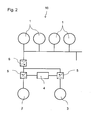
- Fig. 1 and Fig. 2 illustrate two different embodiments of power supply system 10 of onboard floating drilling installations, like semisubmersible drilling rigs or drillships.
- the draw works 2 and the thrusters 3 pull power from the generators 1.
- a control unit is interconnected between the generators 1 and the draw works 2 and the thrusters 3.
- the thrusters 3 used for dynamic positioning and drilling drives of the draw works 2 are interconnected in such a way that the power pull from the generators 2 is kept as stable as possible. This is been done by generating a signal from the draw works 2 representing the power oscillation. This power oscillation signal is superimposed on the control signal for the thrusters 3 adjusting their power consumption to the opposite phase as the draw works 2 and thus generating a constant power delivered from the generators 1.
- an AC bus is used for transfer of the oscillating power. This requires that the rectifiers 6 must be equipped to feed energy in both directions.
- Four-quadrant converter 5 and a control unit 4 are interconnected between the generators 1 and the draw works 2 and the thrusters 3.
- the four-quadrant converter 5 and the control unit 4 enable a refeeding of breaking energy to the grid of the onboard floating drilling installation. That means, during the reeling out or reeling in of the drilling line by the draw works 2 electrical motors of the draw works 2 decelerate the drilling line of the draw works 2. This breaking energy is fed into the grid of the onboard floating drilling installation by the four-quadrant converter 5.
- the DC bus is used for the exchange of the oscillating energy.
- the one way rectifiers 6 and a control unit 4 are interconnected between the generators 1 and the draw works 2 and the thrusters 3.
- the one way rectifiers 6, the control unit 4 and braking resistors enable a compensation of the oscillation of the active power.
Landscapes
- Engineering & Computer Science (AREA)
- Chemical & Material Sciences (AREA)
- Ocean & Marine Engineering (AREA)
- Mechanical Engineering (AREA)
- Life Sciences & Earth Sciences (AREA)
- Combustion & Propulsion (AREA)
- Geology (AREA)
- Mining & Mineral Resources (AREA)
- Environmental & Geological Engineering (AREA)
- Geochemistry & Mineralogy (AREA)
- General Life Sciences & Earth Sciences (AREA)
- Fluid Mechanics (AREA)
- Physics & Mathematics (AREA)
- Power Engineering (AREA)
- Earth Drilling (AREA)
- Other Liquid Machine Or Engine Such As Wave Power Use (AREA)
Claims (16)
- Betriebsverfahren für eine schwimmende Bohreinrichtung an Bord, welche ein Hebewerk (2) zum Abwickeln und Aufwickeln eines Bohrseils umfasst, welche mehrere Strahlruder (3) zum dynamischen Positionieren der schwimmenden Bohreinrichtung an Bord umfasst und welche wenigstens einen Generator (1) umfasst, der elektrischen Strom zum Betreiben der Strahlruder (3) und des Hebewerks (2) erzeugt, wobei das Hebewerk wenigstens einen Antrieb umfasst, wobei das Verfahren durch die folgenden Schritte gekennzeichnet ist:a) Die Leistungsaufnahme des Hebewerks (2) über wenigstens einen bestimmten Zeitraum wird gemessen, und die Leistungsschwingung und der Betrag der Leistungsaufnahme des Hebewerks (2) über den wenigstens einen bestimmten Zeitraum werden bestimmt, wobei die Leistungsschwingung in dem Antrieb des Hebewerks (2) wenigstens teilweise durch Wellen hervorgerufen wird,b) es wird ein auf den Ergebnissen der Messung der Leistungsaufnahme des Hebewerks (2) basierendes Leistungsschwingungssignal erzeugt, wobei das Leistungsschwingungssignal die Leistungsschwingung und den Betrag der Leistungsaufnahme des Hebewerks (2) über den bestimmten Zeitraum repräsentiert,c) es wird ein Anti-Schwingungssignal erzeugt, welches eine Leistungsschwingung mit einer Phasencharakteristik, die zu der des Leistungsschwingungssignals des Hebewerks (2) entgegengesetzt ist, repräsentiert;d) das Anti-Schwingungssignal wird an die Strahlruder (3) verteilt,e) die Leistungsaufnahme der Strahlruder (3) wird an das Anti-Schwingungssignal angepasst.
- Verfahren nach Anspruch 1, dadurch gekennzeichnet, dass eine Steuereinheit (4) der schwimmenden Bohreinrichtung an Bord wenigstens die Schritte b), c) und d) von Anspruch 1 ausführt.
- Verfahren nach wenigstens einem der Ansprüche 1 oder 2, dadurch gekennzeichnet, dass der wenigstens eine Generator (1) elektrischen Strom erzeugt und den elektrischen Strom in das Netz der schwimmenden Bohreinrichtung an Bord einspeist, um das Hebewerk (2) und die Strahlruder (3) zu betreiben.
- Verfahren nach wenigstens einem der Ansprüche 1 bis 3, dadurch gekennzeichnet, dass während des Abwickelns oder Aufwickelns des Bohrseils durch das Hebewerk (2) Elektromotoren des Hebewerks (2) das Bohrseil des Hebewerks (2) verlangsamen.
- Verfahren nach Anspruch 4, dadurch gekennzeichnet, dass die Energie, welche von den Elektromotoren des Hebewerks (2) während der Verlangsamung des Bohrseils erzeugt wird, durch wenigstens einen Vier-Quadranten-Stromrichter (5) in das Netz der schwimmenden Bohreinrichtung an Bord eingespeist wird.
- Verfahren nach wenigstens einem der Ansprüche 1 bis 5, dadurch gekennzeichnet, dass wenigstens ein Bremswiderstand und wenigstens ein Einweggleichrichter (6) die Schwingung der Leistung kompensieren, die von dem Hebewerk (2) und/oder den Strahlrudern (3) benötigt wird.
- Verfahren nach wenigstens einem der Ansprüche 1 bis 6, dadurch gekennzeichnet, dass das Hebewerk (2) und die Strahlruder (3) mit wenigstens einem DC-Bus verbunden sind.
- Verfahren nach wenigstens einem der Ansprüche 1 bis 7, dadurch gekennzeichnet, dass den mehreren Strahlrudern (3) zum dynamischen Positionieren der schwimmenden Bohreinrichtung an Bord von Positionsreferenzsensoren, Bewegungssensoren, Windsensoren und/oder Kreiselkompassen eines dynamischen Positionierungssystems der schwimmenden Bohreinrichtung an Bord Signale zugeführt werden.
- Schwimmende Bohreinrichtung an Bord, welche ein Hebewerk (2) zum Abwickeln und Aufwickeln eines Bohrseils umfasst, welche mehrere Strahlruder (3) zum dynamischen Positionieren der schwimmenden Bohreinrichtung an Bord umfasst und welche wenigstens einen Generator (1) umfasst, der elektrischen Strom zum Betreiben der Strahlruder (3) und des Hebewerks (2) erzeugt, wobei das Hebewerk wenigstens einen Antrieb umfasst, dadurch gekennzeichnet, dass die schwimmende Bohreinrichtung an Bord umfasst: eine Messeinheit zum Messen der Leistungsaufnahme des Hebewerks (2) über wenigstens einen bestimmten Zeitraum, Mittel zum Bestimmen der Leistungsschwingung und des Betrags der Leistungsaufnahme des Hebewerks (2) über den wenigstens einen bestimmten Zeitraum, wobei die Leistungsschwingung in dem Antrieb des Hebewerks (2) wenigstens teilweise durch Wellen hervorgerufen wird, eine erste Erzeugungseinheit zum Erzeugen eines Leistungsschwingungssignals auf der Basis der Ergebnisse der Messung der Leistungsaufnahme des Hebewerks (2), wobei das Leistungsschwingungssignal die Leistungsschwingung und den Betrag der Leistungsaufnahme des Hebewerks (2) über wenigstens den bestimmten Zeitraum repräsentiert, eine zweite Erzeugungseinheit zum Erzeugen eines Anti-Schwingungssignals, welches eine Leistungsschwingung mit einer Phasencharakteristik, die zu der des Leistungsschwingungssignals des Hebewerks (2) entgegengesetzt ist, repräsentiert, eine Verteileinheit zum Verteilen des Anti-Schwingungssignals an die Strahlruder (3) und eine Anpasseinheit zum Anpassen der Leistungsaufnahme der Strahlruder (3) entsprechend dem Anti-Schwingungssignal.
- Schwimmende Bohreinrichtung an Bord nach Anspruch 9, dadurch gekennzeichnet, dass die Messeinheit, die erste und die zweite Erzeugungseinheit und die Verteileinheit Teil einer Steuereinheit (4) der schwimmenden Bohreinrichtung an Bord sind.
- Schwimmende Bohreinrichtung an Bord nach einem der Ansprüche 9 bis 10, dadurch gekennzeichnet, dass das Hebewerk (2) Elektromotoren umfasst, um das Bohrseil des Hebewerks (2) während des Abwickelns oder Aufwickelns des Bohrseils zu verlangsamen.
- Schwimmende Bohreinrichtung an Bord nach einem der Ansprüche 9 bis 11, dadurch gekennzeichnet, dass die schwimmende Bohreinrichtung an Bord wenigstens einen Vier-Quadranten-Stromrichter (5) zum Einspeisen von Energie, welche von den Elektromotoren des Hebewerks (2) während der Verlangsamung des Bohrseils erzeugt wird, in das Netz der schwimmenden Bohreinrichtung an Bord umfasst.
- Schwimmende Bohreinrichtung an Bord nach einem der Ansprüche 9 bis 12, dadurch gekennzeichnet, dass die schwimmende Bohreinrichtung an Bord wenigstens einen Bremswiderstand und wenigstens einen Einweggleichrichter (6) zum Kompensieren der Schwingung der Leistung, die von dem Hebewerk (2) und/oder den Strahlrudern (3) benötigt wird, umfasst.
- Schwimmende Bohreinrichtung an Bord nach einem der Ansprüche 9 bis 13, dadurch gekennzeichnet, dass das Hebewerk (2) und die Strahlruder (3) der schwimmenden Bohreinrichtung an Bord mit wenigstens einem DC-Bus verbunden sind.
- Schwimmende Bohreinrichtung an Bord nach einem der Ansprüche 9 bis 14, dadurch gekennzeichnet, dass die schwimmende Bohreinrichtung an Bord eine Halbtaucher-Bohranlage oder ein Bohrschiff ist.
- Schwimmende Bohreinrichtung an Bord nach einem der Ansprüche 9 bis 15, dadurch gekennzeichnet, dass die schwimmende Bohreinrichtung an Bord ein dynamisches Positionierungssystem mit Positionsreferenzsensoren, Bewegungssensoren, Windsensoren und/oder Kreiselkompassen umfasst, um Strahlrudern (3) Signale zuzuführen, um die schwimmende Bohreinrichtung an Bord in ihrer Position zu halten.
Priority Applications (1)
| Application Number | Priority Date | Filing Date | Title |
|---|---|---|---|
| EP11708879.9A EP2539986B1 (de) | 2010-04-09 | 2011-03-18 | Schwimmende bohreinrichtung an bord und betriebsverfahren für eine schwimmende bohreinrichtung an bord |
Applications Claiming Priority (3)
| Application Number | Priority Date | Filing Date | Title |
|---|---|---|---|
| EP10159486A EP2375530A1 (de) | 2010-04-09 | 2010-04-09 | Schwimmende Bohreinrichtung an Bord und Betriebsverfahren für eine schwimmende Bohreinrichtung an Bord |
| PCT/EP2011/054114 WO2011124459A2 (en) | 2010-04-09 | 2011-03-18 | Onboard floating drilling installation and method for operating an onboard floating drilling installation |
| EP11708879.9A EP2539986B1 (de) | 2010-04-09 | 2011-03-18 | Schwimmende bohreinrichtung an bord und betriebsverfahren für eine schwimmende bohreinrichtung an bord |
Publications (2)
| Publication Number | Publication Date |
|---|---|
| EP2539986A2 EP2539986A2 (de) | 2013-01-02 |
| EP2539986B1 true EP2539986B1 (de) | 2015-10-28 |
Family
ID=42830594
Family Applications (2)
| Application Number | Title | Priority Date | Filing Date |
|---|---|---|---|
| EP10159486A Withdrawn EP2375530A1 (de) | 2010-04-09 | 2010-04-09 | Schwimmende Bohreinrichtung an Bord und Betriebsverfahren für eine schwimmende Bohreinrichtung an Bord |
| EP11708879.9A Not-in-force EP2539986B1 (de) | 2010-04-09 | 2011-03-18 | Schwimmende bohreinrichtung an bord und betriebsverfahren für eine schwimmende bohreinrichtung an bord |
Family Applications Before (1)
| Application Number | Title | Priority Date | Filing Date |
|---|---|---|---|
| EP10159486A Withdrawn EP2375530A1 (de) | 2010-04-09 | 2010-04-09 | Schwimmende Bohreinrichtung an Bord und Betriebsverfahren für eine schwimmende Bohreinrichtung an Bord |
Country Status (7)
| Country | Link |
|---|---|
| US (1) | US8951078B2 (de) |
| EP (2) | EP2375530A1 (de) |
| KR (1) | KR101912594B1 (de) |
| CN (1) | CN102918736B (de) |
| BR (1) | BR112012025807B1 (de) |
| DK (1) | DK2539986T3 (de) |
| WO (1) | WO2011124459A2 (de) |
Families Citing this family (4)
| Publication number | Priority date | Publication date | Assignee | Title |
|---|---|---|---|---|
| EP3196116A4 (de) * | 2014-08-22 | 2018-05-02 | Daewoo Shipbuilding & Marine Engineering Co., Ltd. | Vorrichtung und verfahren zur steuerung und überwachung einer hilfsvorrichtung einer bohrausrüstung bei einem bohrschiff |
| CN104635699B (zh) * | 2015-01-15 | 2017-05-31 | 上海中远船务工程有限公司 | Dp3超深水钻井设备配电系统 |
| WO2018165461A1 (en) * | 2017-03-08 | 2018-09-13 | Zentech, Inc. | Dynamically positioned liquid mud plant vessel |
| US20200295640A1 (en) * | 2019-03-15 | 2020-09-17 | Baker Hughes Oilfield Operations Llc | Power generation with speed dependent magnetic field control |
Family Cites Families (26)
| Publication number | Priority date | Publication date | Assignee | Title |
|---|---|---|---|---|
| US2966221A (en) * | 1956-11-23 | 1960-12-27 | Union Oil Co | Well drilling process and apparatus |
| US3552343A (en) * | 1969-01-10 | 1971-01-05 | Pan American Petroleum Corp | Drilling ship mooring system |
| US3653636A (en) * | 1970-02-09 | 1972-04-04 | Exxon Production Research Co | Wave motion compensation system for suspending well equipment from a floating vessel |
| US3804183A (en) | 1972-05-01 | 1974-04-16 | Rucker Co | Drill string compensator |
| IT1009574B (it) * | 1974-01-21 | 1976-12-20 | Saipem Spa | Metodo perfezionato per il posizio namento di un natante in particola re di una nave di perforazione e relativi dispositvi |
| US4167147A (en) * | 1976-01-19 | 1979-09-11 | Seatek Corp. | Method and apparatus for stabilizing a floating structure |
| US4205379A (en) * | 1977-05-16 | 1980-05-27 | TRW Inc., Systems & Energy | Position determining and dynamic positioning method and system for floating marine well drill platforms and the like |
| US4232903A (en) | 1978-12-28 | 1980-11-11 | Lockheed Missiles & Space Co., Inc. | Ocean mining system and process |
| US4516882A (en) | 1982-06-11 | 1985-05-14 | Fluor Subsea Services, Inc. | Method and apparatus for conversion of semi-submersible platform to tension leg platform for conducting offshore well operations |
| US5894895A (en) * | 1996-11-25 | 1999-04-20 | Welsh; Walter Thomas | Heave compensator for drill ships |
| GB9807070D0 (en) | 1998-04-01 | 1998-06-03 | Seabed Impeller Levelling And | Dredging apparatus |
| EP1187760B1 (de) * | 1999-06-24 | 2004-04-14 | Siemens Aktiengesellschaft | Antriebs- und fahrsystem für schiffe |
| US20020035957A1 (en) * | 2000-02-04 | 2002-03-28 | Fischer Ferdinand J. | Thruster apparatus and method for reducing fluid-induced motions of and stresses within an offshore platform |
| US7958715B2 (en) | 2003-03-13 | 2011-06-14 | National Oilwell Varco, L.P. | Chain with identification apparatus |
| US6932326B1 (en) | 2003-06-13 | 2005-08-23 | Richard L. Krabbendam | Method for lifting and transporting a heavy load using a fly-jib |
| WO2005002038A1 (ja) * | 2003-06-26 | 2005-01-06 | Toshiba Mitsubishi-Electric Industrial Systems Corporation | 電動機駆動システム |
| US9784041B2 (en) | 2004-04-15 | 2017-10-10 | National Oilwell Varco L.P. | Drilling rig riser identification apparatus |
| NO321428B1 (no) | 2004-06-04 | 2006-05-08 | Wartsila Automation Norway As | Kraftforsyningssystem |
| NO320841B1 (no) | 2004-06-08 | 2006-01-30 | Marine Cybernetics As | Fremgangsmate for testing av et kombinert dynamisk posisjonerings- og kraftreguleringssystem |
| GB2449119B (en) | 2007-05-11 | 2012-02-29 | Converteam Technology Ltd | Power converters |
| US8513911B2 (en) | 2007-05-11 | 2013-08-20 | Converteam Technology Ltd. | Power converters |
| US20090195074A1 (en) * | 2008-01-31 | 2009-08-06 | Buiel Edward R | Power supply and storage device for improving drilling rig operating efficiency |
| US8858277B2 (en) | 2008-07-14 | 2014-10-14 | General Electric Company | System and method for dynamic energy recovery in marine propulsion |
| US7918696B2 (en) * | 2008-07-14 | 2011-04-05 | General Electric Company | System and method for dynamic energy recovery in marine propulsion |
| NO330667B1 (no) * | 2009-02-13 | 2011-06-06 | Wartsila Norway As | System for kraftforsyning, saerlig pa rigg |
| EP2569844B1 (de) | 2010-04-09 | 2017-05-31 | Siemens Aktiengesellschaft | Energieversorgungssystem für ein marines bohrschiff |
-
2010
- 2010-04-09 EP EP10159486A patent/EP2375530A1/de not_active Withdrawn
-
2011
- 2011-03-18 CN CN201180028237.5A patent/CN102918736B/zh not_active Expired - Fee Related
- 2011-03-18 EP EP11708879.9A patent/EP2539986B1/de not_active Not-in-force
- 2011-03-18 WO PCT/EP2011/054114 patent/WO2011124459A2/en not_active Ceased
- 2011-03-18 BR BR112012025807-9A patent/BR112012025807B1/pt not_active IP Right Cessation
- 2011-03-18 DK DK11708879.9T patent/DK2539986T3/en active
- 2011-03-18 KR KR1020127029520A patent/KR101912594B1/ko not_active Expired - Fee Related
- 2011-03-18 US US13/639,537 patent/US8951078B2/en not_active Expired - Fee Related
Also Published As
| Publication number | Publication date |
|---|---|
| WO2011124459A3 (en) | 2012-03-01 |
| BR112012025807A2 (pt) | 2016-06-28 |
| US20130078875A1 (en) | 2013-03-28 |
| DK2539986T3 (en) | 2016-01-25 |
| KR101912594B1 (ko) | 2018-10-29 |
| US8951078B2 (en) | 2015-02-10 |
| CN102918736A (zh) | 2013-02-06 |
| WO2011124459A2 (en) | 2011-10-13 |
| EP2375530A1 (de) | 2011-10-12 |
| KR20130040195A (ko) | 2013-04-23 |
| CN102918736B (zh) | 2015-07-22 |
| BR112012025807B1 (pt) | 2021-03-09 |
| EP2539986A2 (de) | 2013-01-02 |
Similar Documents
| Publication | Publication Date | Title |
|---|---|---|
| EP2569844B1 (de) | Energieversorgungssystem für ein marines bohrschiff | |
| KR101533392B1 (ko) | 롤 감쇠 기계장치를 구비하는 선박 | |
| US7806065B1 (en) | Modular system for fast and easy conversion of anchor moored semi-submersibles to dynamically positioned semis without the need for dry docking, using a diesel electric thruster system | |
| JP6242493B2 (ja) | 海上プラントのハイブリッド電力供給装置及び方法 | |
| EP2539986B1 (de) | Schwimmende bohreinrichtung an bord und betriebsverfahren für eine schwimmende bohreinrichtung an bord | |
| NO20131159A1 (no) | Effektstyring i sjøfartøyer | |
| CN109747784B (zh) | 船海工程单点系泊锚桨联合协同定位系统及方法 | |
| KR20160025815A (ko) | 해양 플랜트의 전력 공급 장치 및 상기 전력 공급 장치를 포함하는 해양 플랜트 | |
| KR20130051666A (ko) | 윈드 터빈을 구비하는 드릴십 | |
| KR102503162B1 (ko) | 해양구조물용 추진 장치 및 해양구조물 | |
| KR102196986B1 (ko) | 드릴십 | |
| Hammett | SEDCO-445 Dynamic stationed drill ship | |
| KR101739465B1 (ko) | 해양플랜트의 전력 제어 장치 | |
| KR101637432B1 (ko) | 해양플랜트의 전력 제어 장치 | |
| KR20190004571A (ko) | 드릴십 | |
| KR20160039896A (ko) | 해양플랜트의 전력 제어 장치 및 방법 | |
| KR20160023197A (ko) | 해양 플랜트의 하이브리드 전력 공급 장치 및 방법 |
Legal Events
| Date | Code | Title | Description |
|---|---|---|---|
| PUAI | Public reference made under article 153(3) epc to a published international application that has entered the european phase |
Free format text: ORIGINAL CODE: 0009012 |
|
| 17P | Request for examination filed |
Effective date: 20120925 |
|
| AK | Designated contracting states |
Kind code of ref document: A2 Designated state(s): AL AT BE BG CH CY CZ DE DK EE ES FI FR GB GR HR HU IE IS IT LI LT LU LV MC MK MT NL NO PL PT RO RS SE SI SK SM TR |
|
| RAP1 | Party data changed (applicant data changed or rights of an application transferred) |
Owner name: SIEMENS AKTIENGESELLSCHAFT |
|
| DAX | Request for extension of the european patent (deleted) | ||
| REG | Reference to a national code |
Ref country code: DE Ref legal event code: R079 Ref document number: 602011020977 Country of ref document: DE Free format text: PREVIOUS MAIN CLASS: H02J0003380000 Ipc: B63J0003020000 |
|
| GRAP | Despatch of communication of intention to grant a patent |
Free format text: ORIGINAL CODE: EPIDOSNIGR1 |
|
| RIC1 | Information provided on ipc code assigned before grant |
Ipc: E21B 41/00 20060101ALN20150430BHEP Ipc: B63J 3/02 20060101AFI20150430BHEP Ipc: B63H 21/17 20060101ALI20150430BHEP Ipc: B63J 3/04 20060101ALI20150430BHEP |
|
| RIC1 | Information provided on ipc code assigned before grant |
Ipc: B63J 3/02 20060101AFI20150505BHEP Ipc: E21B 41/00 20060101ALN20150505BHEP Ipc: B63H 21/17 20060101ALI20150505BHEP Ipc: B63J 3/04 20060101ALI20150505BHEP |
|
| INTG | Intention to grant announced |
Effective date: 20150529 |
|
| GRAS | Grant fee paid |
Free format text: ORIGINAL CODE: EPIDOSNIGR3 |
|
| GRAA | (expected) grant |
Free format text: ORIGINAL CODE: 0009210 |
|
| AK | Designated contracting states |
Kind code of ref document: B1 Designated state(s): AL AT BE BG CH CY CZ DE DK EE ES FI FR GB GR HR HU IE IS IT LI LT LU LV MC MK MT NL NO PL PT RO RS SE SI SK SM TR |
|
| REG | Reference to a national code |
Ref country code: GB Ref legal event code: FG4D |
|
| REG | Reference to a national code |
Ref country code: CH Ref legal event code: EP |
|
| REG | Reference to a national code |
Ref country code: AT Ref legal event code: REF Ref document number: 757775 Country of ref document: AT Kind code of ref document: T Effective date: 20151115 |
|
| REG | Reference to a national code |
Ref country code: IE Ref legal event code: FG4D |
|
| REG | Reference to a national code |
Ref country code: DE Ref legal event code: R096 Ref document number: 602011020977 Country of ref document: DE |
|
| REG | Reference to a national code |
Ref country code: DK Ref legal event code: T3 Effective date: 20160122 |
|
| REG | Reference to a national code |
Ref country code: NL Ref legal event code: FP |
|
| REG | Reference to a national code |
Ref country code: LT Ref legal event code: MG4D |
|
| REG | Reference to a national code |
Ref country code: NO Ref legal event code: T2 Effective date: 20151028 |
|
| REG | Reference to a national code |
Ref country code: AT Ref legal event code: MK05 Ref document number: 757775 Country of ref document: AT Kind code of ref document: T Effective date: 20151028 |
|
| PG25 | Lapsed in a contracting state [announced via postgrant information from national office to epo] |
Ref country code: HR Free format text: LAPSE BECAUSE OF FAILURE TO SUBMIT A TRANSLATION OF THE DESCRIPTION OR TO PAY THE FEE WITHIN THE PRESCRIBED TIME-LIMIT Effective date: 20151028 Ref country code: LT Free format text: LAPSE BECAUSE OF FAILURE TO SUBMIT A TRANSLATION OF THE DESCRIPTION OR TO PAY THE FEE WITHIN THE PRESCRIBED TIME-LIMIT Effective date: 20151028 Ref country code: IT Free format text: LAPSE BECAUSE OF FAILURE TO SUBMIT A TRANSLATION OF THE DESCRIPTION OR TO PAY THE FEE WITHIN THE PRESCRIBED TIME-LIMIT Effective date: 20151028 Ref country code: IS Free format text: LAPSE BECAUSE OF FAILURE TO SUBMIT A TRANSLATION OF THE DESCRIPTION OR TO PAY THE FEE WITHIN THE PRESCRIBED TIME-LIMIT Effective date: 20160228 Ref country code: ES Free format text: LAPSE BECAUSE OF FAILURE TO SUBMIT A TRANSLATION OF THE DESCRIPTION OR TO PAY THE FEE WITHIN THE PRESCRIBED TIME-LIMIT Effective date: 20151028 |
|
| PG25 | Lapsed in a contracting state [announced via postgrant information from national office to epo] |
Ref country code: FI Free format text: LAPSE BECAUSE OF FAILURE TO SUBMIT A TRANSLATION OF THE DESCRIPTION OR TO PAY THE FEE WITHIN THE PRESCRIBED TIME-LIMIT Effective date: 20151028 Ref country code: AT Free format text: LAPSE BECAUSE OF FAILURE TO SUBMIT A TRANSLATION OF THE DESCRIPTION OR TO PAY THE FEE WITHIN THE PRESCRIBED TIME-LIMIT Effective date: 20151028 Ref country code: RS Free format text: LAPSE BECAUSE OF FAILURE TO SUBMIT A TRANSLATION OF THE DESCRIPTION OR TO PAY THE FEE WITHIN THE PRESCRIBED TIME-LIMIT Effective date: 20151028 Ref country code: SE Free format text: LAPSE BECAUSE OF FAILURE TO SUBMIT A TRANSLATION OF THE DESCRIPTION OR TO PAY THE FEE WITHIN THE PRESCRIBED TIME-LIMIT Effective date: 20151028 Ref country code: PL Free format text: LAPSE BECAUSE OF FAILURE TO SUBMIT A TRANSLATION OF THE DESCRIPTION OR TO PAY THE FEE WITHIN THE PRESCRIBED TIME-LIMIT Effective date: 20151028 Ref country code: GR Free format text: LAPSE BECAUSE OF FAILURE TO SUBMIT A TRANSLATION OF THE DESCRIPTION OR TO PAY THE FEE WITHIN THE PRESCRIBED TIME-LIMIT Effective date: 20160129 Ref country code: LV Free format text: LAPSE BECAUSE OF FAILURE TO SUBMIT A TRANSLATION OF THE DESCRIPTION OR TO PAY THE FEE WITHIN THE PRESCRIBED TIME-LIMIT Effective date: 20151028 Ref country code: PT Free format text: LAPSE BECAUSE OF FAILURE TO SUBMIT A TRANSLATION OF THE DESCRIPTION OR TO PAY THE FEE WITHIN THE PRESCRIBED TIME-LIMIT Effective date: 20160229 |
|
| PG25 | Lapsed in a contracting state [announced via postgrant information from national office to epo] |
Ref country code: CZ Free format text: LAPSE BECAUSE OF FAILURE TO SUBMIT A TRANSLATION OF THE DESCRIPTION OR TO PAY THE FEE WITHIN THE PRESCRIBED TIME-LIMIT Effective date: 20151028 |
|
| REG | Reference to a national code |
Ref country code: DE Ref legal event code: R097 Ref document number: 602011020977 Country of ref document: DE |
|
| PG25 | Lapsed in a contracting state [announced via postgrant information from national office to epo] |
Ref country code: EE Free format text: LAPSE BECAUSE OF FAILURE TO SUBMIT A TRANSLATION OF THE DESCRIPTION OR TO PAY THE FEE WITHIN THE PRESCRIBED TIME-LIMIT Effective date: 20151028 Ref country code: RO Free format text: LAPSE BECAUSE OF FAILURE TO SUBMIT A TRANSLATION OF THE DESCRIPTION OR TO PAY THE FEE WITHIN THE PRESCRIBED TIME-LIMIT Effective date: 20151028 Ref country code: SM Free format text: LAPSE BECAUSE OF FAILURE TO SUBMIT A TRANSLATION OF THE DESCRIPTION OR TO PAY THE FEE WITHIN THE PRESCRIBED TIME-LIMIT Effective date: 20151028 Ref country code: BE Free format text: LAPSE BECAUSE OF NON-PAYMENT OF DUE FEES Effective date: 20160331 Ref country code: SK Free format text: LAPSE BECAUSE OF FAILURE TO SUBMIT A TRANSLATION OF THE DESCRIPTION OR TO PAY THE FEE WITHIN THE PRESCRIBED TIME-LIMIT Effective date: 20151028 |
|
| PLBE | No opposition filed within time limit |
Free format text: ORIGINAL CODE: 0009261 |
|
| STAA | Information on the status of an ep patent application or granted ep patent |
Free format text: STATUS: NO OPPOSITION FILED WITHIN TIME LIMIT |
|
| 26N | No opposition filed |
Effective date: 20160729 |
|
| PG25 | Lapsed in a contracting state [announced via postgrant information from national office to epo] |
Ref country code: MC Free format text: LAPSE BECAUSE OF FAILURE TO SUBMIT A TRANSLATION OF THE DESCRIPTION OR TO PAY THE FEE WITHIN THE PRESCRIBED TIME-LIMIT Effective date: 20151028 Ref country code: LU Free format text: LAPSE BECAUSE OF FAILURE TO SUBMIT A TRANSLATION OF THE DESCRIPTION OR TO PAY THE FEE WITHIN THE PRESCRIBED TIME-LIMIT Effective date: 20160318 |
|
| REG | Reference to a national code |
Ref country code: CH Ref legal event code: PL |
|
| PG25 | Lapsed in a contracting state [announced via postgrant information from national office to epo] |
Ref country code: SI Free format text: LAPSE BECAUSE OF FAILURE TO SUBMIT A TRANSLATION OF THE DESCRIPTION OR TO PAY THE FEE WITHIN THE PRESCRIBED TIME-LIMIT Effective date: 20151028 |
|
| REG | Reference to a national code |
Ref country code: IE Ref legal event code: MM4A |
|
| PG25 | Lapsed in a contracting state [announced via postgrant information from national office to epo] |
Ref country code: BE Free format text: LAPSE BECAUSE OF FAILURE TO SUBMIT A TRANSLATION OF THE DESCRIPTION OR TO PAY THE FEE WITHIN THE PRESCRIBED TIME-LIMIT Effective date: 20151028 |
|
| REG | Reference to a national code |
Ref country code: FR Ref legal event code: ST Effective date: 20161130 |
|
| PG25 | Lapsed in a contracting state [announced via postgrant information from national office to epo] |
Ref country code: CH Free format text: LAPSE BECAUSE OF NON-PAYMENT OF DUE FEES Effective date: 20160331 Ref country code: FR Free format text: LAPSE BECAUSE OF NON-PAYMENT OF DUE FEES Effective date: 20160331 Ref country code: IE Free format text: LAPSE BECAUSE OF NON-PAYMENT OF DUE FEES Effective date: 20160318 Ref country code: LI Free format text: LAPSE BECAUSE OF NON-PAYMENT OF DUE FEES Effective date: 20160331 |
|
| PGFP | Annual fee paid to national office [announced via postgrant information from national office to epo] |
Ref country code: DE Payment date: 20170519 Year of fee payment: 7 |
|
| PG25 | Lapsed in a contracting state [announced via postgrant information from national office to epo] |
Ref country code: MT Free format text: LAPSE BECAUSE OF FAILURE TO SUBMIT A TRANSLATION OF THE DESCRIPTION OR TO PAY THE FEE WITHIN THE PRESCRIBED TIME-LIMIT Effective date: 20151028 |
|
| PGFP | Annual fee paid to national office [announced via postgrant information from national office to epo] |
Ref country code: DK Payment date: 20180321 Year of fee payment: 8 |
|
| PG25 | Lapsed in a contracting state [announced via postgrant information from national office to epo] |
Ref country code: CY Free format text: LAPSE BECAUSE OF FAILURE TO SUBMIT A TRANSLATION OF THE DESCRIPTION OR TO PAY THE FEE WITHIN THE PRESCRIBED TIME-LIMIT Effective date: 20151028 Ref country code: HU Free format text: LAPSE BECAUSE OF FAILURE TO SUBMIT A TRANSLATION OF THE DESCRIPTION OR TO PAY THE FEE WITHIN THE PRESCRIBED TIME-LIMIT; INVALID AB INITIO Effective date: 20110318 |
|
| PG25 | Lapsed in a contracting state [announced via postgrant information from national office to epo] |
Ref country code: MK Free format text: LAPSE BECAUSE OF FAILURE TO SUBMIT A TRANSLATION OF THE DESCRIPTION OR TO PAY THE FEE WITHIN THE PRESCRIBED TIME-LIMIT Effective date: 20151028 Ref country code: MT Free format text: LAPSE BECAUSE OF FAILURE TO SUBMIT A TRANSLATION OF THE DESCRIPTION OR TO PAY THE FEE WITHIN THE PRESCRIBED TIME-LIMIT Effective date: 20160331 Ref country code: TR Free format text: LAPSE BECAUSE OF FAILURE TO SUBMIT A TRANSLATION OF THE DESCRIPTION OR TO PAY THE FEE WITHIN THE PRESCRIBED TIME-LIMIT Effective date: 20151028 |
|
| PG25 | Lapsed in a contracting state [announced via postgrant information from national office to epo] |
Ref country code: BG Free format text: LAPSE BECAUSE OF FAILURE TO SUBMIT A TRANSLATION OF THE DESCRIPTION OR TO PAY THE FEE WITHIN THE PRESCRIBED TIME-LIMIT Effective date: 20151028 |
|
| REG | Reference to a national code |
Ref country code: DE Ref legal event code: R119 Ref document number: 602011020977 Country of ref document: DE |
|
| PG25 | Lapsed in a contracting state [announced via postgrant information from national office to epo] |
Ref country code: AL Free format text: LAPSE BECAUSE OF FAILURE TO SUBMIT A TRANSLATION OF THE DESCRIPTION OR TO PAY THE FEE WITHIN THE PRESCRIBED TIME-LIMIT Effective date: 20151028 |
|
| PG25 | Lapsed in a contracting state [announced via postgrant information from national office to epo] |
Ref country code: DE Free format text: LAPSE BECAUSE OF NON-PAYMENT OF DUE FEES Effective date: 20181002 |
|
| REG | Reference to a national code |
Ref country code: DK Ref legal event code: EBP Effective date: 20190331 |
|
| PG25 | Lapsed in a contracting state [announced via postgrant information from national office to epo] |
Ref country code: DK Free format text: LAPSE BECAUSE OF NON-PAYMENT OF DUE FEES Effective date: 20190331 |
|
| REG | Reference to a national code |
Ref country code: NL Ref legal event code: PD Owner name: SIEMENS ENERGY AS; NO Free format text: DETAILS ASSIGNMENT: CHANGE OF OWNER(S), ASSIGNMENT; FORMER OWNER NAME: SIEMENS AKTIENGESELLSCHAFT Effective date: 20210318 |
|
| REG | Reference to a national code |
Ref country code: NO Ref legal event code: CHAD Owner name: SIEMENS ENERGY AS, NO |
|
| REG | Reference to a national code |
Ref country code: GB Ref legal event code: 732E Free format text: REGISTERED BETWEEN 20210325 AND 20210331 |
|
| PGFP | Annual fee paid to national office [announced via postgrant information from national office to epo] |
Ref country code: NO Payment date: 20210304 Year of fee payment: 11 Ref country code: NL Payment date: 20210302 Year of fee payment: 11 |
|
| PGFP | Annual fee paid to national office [announced via postgrant information from national office to epo] |
Ref country code: GB Payment date: 20210406 Year of fee payment: 11 |
|
| REG | Reference to a national code |
Ref country code: NO Ref legal event code: MMEP |
|
| REG | Reference to a national code |
Ref country code: NL Ref legal event code: MM Effective date: 20220401 |
|
| GBPC | Gb: european patent ceased through non-payment of renewal fee |
Effective date: 20220318 |
|
| PG25 | Lapsed in a contracting state [announced via postgrant information from national office to epo] |
Ref country code: NO Free format text: LAPSE BECAUSE OF NON-PAYMENT OF DUE FEES Effective date: 20220331 Ref country code: NL Free format text: LAPSE BECAUSE OF NON-PAYMENT OF DUE FEES Effective date: 20220401 Ref country code: GB Free format text: LAPSE BECAUSE OF NON-PAYMENT OF DUE FEES Effective date: 20220318 |