EP2539648B1 - Machine à glaçons, réfrigérateur ayant celle-ci, et procédé de distribution de glaçons de celui-ci - Google Patents
Machine à glaçons, réfrigérateur ayant celle-ci, et procédé de distribution de glaçons de celui-ci Download PDFInfo
- Publication number
- EP2539648B1 EP2539648B1 EP11747681.2A EP11747681A EP2539648B1 EP 2539648 B1 EP2539648 B1 EP 2539648B1 EP 11747681 A EP11747681 A EP 11747681A EP 2539648 B1 EP2539648 B1 EP 2539648B1
- Authority
- EP
- European Patent Office
- Prior art keywords
- ice
- ice making
- making container
- water
- container
- Prior art date
- Legal status (The legal status is an assumption and is not a legal conclusion. Google has not performed a legal analysis and makes no representation as to the accuracy of the status listed.)
- Active
Links
- 238000000034 method Methods 0.000 title claims description 28
- XLYOFNOQVPJJNP-UHFFFAOYSA-N water Substances O XLYOFNOQVPJJNP-UHFFFAOYSA-N 0.000 claims description 146
- 238000005192 partition Methods 0.000 claims description 37
- 238000003860 storage Methods 0.000 claims description 29
- 238000000638 solvent extraction Methods 0.000 claims description 23
- 238000007710 freezing Methods 0.000 claims description 19
- 230000008014 freezing Effects 0.000 claims description 19
- 238000001514 detection method Methods 0.000 claims description 6
- 230000000903 blocking effect Effects 0.000 claims description 3
- 239000000463 material Substances 0.000 description 11
- XAGFODPZIPBFFR-UHFFFAOYSA-N aluminium Chemical compound [Al] XAGFODPZIPBFFR-UHFFFAOYSA-N 0.000 description 4
- 229910052782 aluminium Inorganic materials 0.000 description 4
- 238000010586 diagram Methods 0.000 description 4
- YCKRFDGAMUMZLT-UHFFFAOYSA-N Fluorine atom Chemical compound [F] YCKRFDGAMUMZLT-UHFFFAOYSA-N 0.000 description 3
- 230000000694 effects Effects 0.000 description 3
- 229910052731 fluorine Inorganic materials 0.000 description 3
- 239000011737 fluorine Substances 0.000 description 3
- 230000004888 barrier function Effects 0.000 description 2
- 239000000919 ceramic Substances 0.000 description 2
- 238000005520 cutting process Methods 0.000 description 2
- 238000010438 heat treatment Methods 0.000 description 2
- 230000001678 irradiating effect Effects 0.000 description 2
- 238000004519 manufacturing process Methods 0.000 description 2
- 230000003746 surface roughness Effects 0.000 description 2
- 230000004308 accommodation Effects 0.000 description 1
- 229920001940 conductive polymer Polymers 0.000 description 1
- 239000004020 conductor Substances 0.000 description 1
- 238000001816 cooling Methods 0.000 description 1
- 230000005611 electricity Effects 0.000 description 1
- 239000010408 film Substances 0.000 description 1
- 239000012530 fluid Substances 0.000 description 1
- 125000001153 fluoro group Chemical group F* 0.000 description 1
- 238000003780 insertion Methods 0.000 description 1
- 230000037431 insertion Effects 0.000 description 1
- 238000002844 melting Methods 0.000 description 1
- 230000008018 melting Effects 0.000 description 1
- 238000000926 separation method Methods 0.000 description 1
- 229910052710 silicon Inorganic materials 0.000 description 1
- 239000010703 silicon Substances 0.000 description 1
- 239000008400 supply water Substances 0.000 description 1
- 239000010409 thin film Substances 0.000 description 1
Images


Classifications
-
- F—MECHANICAL ENGINEERING; LIGHTING; HEATING; WEAPONS; BLASTING
- F25—REFRIGERATION OR COOLING; COMBINED HEATING AND REFRIGERATION SYSTEMS; HEAT PUMP SYSTEMS; MANUFACTURE OR STORAGE OF ICE; LIQUEFACTION SOLIDIFICATION OF GASES
- F25C—PRODUCING, WORKING OR HANDLING ICE
- F25C5/00—Working or handling ice
- F25C5/02—Apparatus for disintegrating, removing or harvesting ice
- F25C5/04—Apparatus for disintegrating, removing or harvesting ice without the use of saws
- F25C5/08—Apparatus for disintegrating, removing or harvesting ice without the use of saws by heating bodies in contact with the ice
-
- F—MECHANICAL ENGINEERING; LIGHTING; HEATING; WEAPONS; BLASTING
- F25—REFRIGERATION OR COOLING; COMBINED HEATING AND REFRIGERATION SYSTEMS; HEAT PUMP SYSTEMS; MANUFACTURE OR STORAGE OF ICE; LIQUEFACTION SOLIDIFICATION OF GASES
- F25C—PRODUCING, WORKING OR HANDLING ICE
- F25C1/00—Producing ice
- F25C1/04—Producing ice by using stationary moulds
-
- F—MECHANICAL ENGINEERING; LIGHTING; HEATING; WEAPONS; BLASTING
- F25—REFRIGERATION OR COOLING; COMBINED HEATING AND REFRIGERATION SYSTEMS; HEAT PUMP SYSTEMS; MANUFACTURE OR STORAGE OF ICE; LIQUEFACTION SOLIDIFICATION OF GASES
- F25C—PRODUCING, WORKING OR HANDLING ICE
- F25C2305/00—Special arrangements or features for working or handling ice
- F25C2305/022—Harvesting ice including rotating or tilting or pivoting of a mould or tray
- F25C2305/0221—Harvesting ice including rotating or tilting or pivoting of a mould or tray rotating ice mould
-
- F—MECHANICAL ENGINEERING; LIGHTING; HEATING; WEAPONS; BLASTING
- F25—REFRIGERATION OR COOLING; COMBINED HEATING AND REFRIGERATION SYSTEMS; HEAT PUMP SYSTEMS; MANUFACTURE OR STORAGE OF ICE; LIQUEFACTION SOLIDIFICATION OF GASES
- F25C—PRODUCING, WORKING OR HANDLING ICE
- F25C2305/00—Special arrangements or features for working or handling ice
- F25C2305/024—Rotating rake
-
- F—MECHANICAL ENGINEERING; LIGHTING; HEATING; WEAPONS; BLASTING
- F25—REFRIGERATION OR COOLING; COMBINED HEATING AND REFRIGERATION SYSTEMS; HEAT PUMP SYSTEMS; MANUFACTURE OR STORAGE OF ICE; LIQUEFACTION SOLIDIFICATION OF GASES
- F25C—PRODUCING, WORKING OR HANDLING ICE
- F25C2600/00—Control issues
- F25C2600/04—Control means
Definitions
- the present invention relates to an ice maker, a refrigerator having the same, and a method for supplying ice of the refrigerator and, more particularly, to an ice maker having a small occupancy area and high space utilization, a refrigerator having the same, and a method for supplying ice of the refrigerator.
- a household refrigerator is a device having a certain accommodation space to keep food items, or the like, at a low temperature, which is divided into a refrigerating chamber maintained above zero in a low temperature range and a freezing chamber maintained below zero in the low temperature range.
- the automatic ice maker (referred to as an ice maker , hereinafter) may be installed in the freezing chamber or in the refrigerating chamber according to the types of refrigerators.
- an ice maker When the ice maker is installed in the refrigerating chamber, cold air in the freezing chamber is guided (or provided) to the ice maker to make ice.
- the ice maker has an ejector installed at an upper side of the ice making container in order to push up and separate ice from the ice making container, while being rotated.
- the ice storage container for keeping ice released from the ice making container in storage is positioned at the front side of the ice making container, and accordingly, the area occupied by the ice maker, namely, the area in a forward/backward direction, is increased, having a limitation in fabricating a thinner refrigerator door.
- the ice making container in order to release ice from the ice making container, the ice making container is heated by using a heater.
- the use of the heater increases power consumption and generates a large amount of residual water.
- US 3 206 940 A describes an ice cube making device.
- the ice cube making device comprises a rectangular framework. Positioned within the framework is an ice cube mold.
- the mold comprises a tray having outwardly slanted front and rear end walls and side walls.
- the mold further comprises a pocket-defining grid structure composed of a plurality of vertically parallel divider plates which extend horizontally from an elongated carrier plate overlying one of the side walls of the tray.
- US 2 962 876 A describes an ice block ice making apparatus comprising an ice block tray. Disposed within the tray is a grid structure designed to subdivide the tray into a plurality of small divisions in which fluid, such as water, may be frozen to provide ice blocks.
- the grid structure comprises a vertical plate extending along the full length of the tray interior. A plurality of vertical divider plates is disposed generally normal to the vertical plate.
- an object of the present invention is to provide a refrigerator in which when ice is released from an ice making container, it is directly from the ice making container, thus reducing the area in a forward/backward direction occupied by the ice making container and an ice storage container, and a method for operating the refrigerator.
- Another object of the present invention is to provide a refrigerator in which a surface roughness of an ice making container is enhanced to uniformly heat the ice making container and reduce generation of residual water, and a method for operating the refrigerator.
- Another object of the present invention is to provide a refrigerator in which ice can be released without heating an ice making container, thus reducing the number of components, reducing power consumption, and reducing residual water, and a method for operating the refrigerator.
- an ice maker preferably including: an ice making container having an ice making space to allow water to be put therein to make ice; a partitioning plate having a plurality of partition walls to demarcate the ice making space into a plurality of unit spaces; and a driving unit for supplying a rotary force to the ice making container to allow the ice making container to rotate with respect to the partitioning plate to release ice of the ice making space.
- a refrigerator preferably including: a refrigerator main body having an ice making chamber; and an ice maker provided in an ice making chamber of the refrigerator main body, wherein the ice maker includes: an ice making container having an ice making space to allow water to be put therein to make ice; a partitioning plate having a plurality of partition walls to demarcate the ice making space into a plurality of unit spaces; and a driving unit for supplying a rotary force to the ice making container to allow the ice making container to rotate with respect to the partitioning plate to release ice of the ice making space.
- a method for supplying ice preferably including: making ice in an ice maker; receiving an ice dispense signal from a user; rotating an ice making container of the ice maker; separating ice from the ice maker; and dispensing the separated ice.
- the refrigerator having the same, and the method for supplying ice of the refrigerator according to exemplary embodiments of the present invention, because ice freefalls to be released as the ice making container is rotated, the size of the ice maker can be reduced and the area occupied by the ice maker can be reduced to make a refrigerator slimmer.
- the use of a heater for releasing ice can be omitted, and accordingly, power consumption can re reduced and residual water which may be generated when a heater is used can be reduced.
- a partitioning plate is separately provided without forming a partition wall on an inner circumferential surface of the ice making container, the roughness of the inner circumferential surface of the ice making container can be enhanced. Accordingly, heat can be uniformly transferred in the ice making container, reducing a generation amount of residual water in the ice releasing operation and preventing stored ice cubes from being entangled.
- the ice releasing heater for releasing ice from the ice making container is installed on the partitioning plate, a fixed body, the ice making container can be easily driven, facilitating the fabrication of the ice making container and reducing power consumption.
- ice of the ice making container When the ice making container is rotated, ice of the ice making container freefalls to be released, thus reducing the size of the ice maker and making a refrigerator slimmer. Also, since a partition wall is not provided on an inner circumferential surface of the ice making container, the roughness of the inner circumferential surface of the ice making container can be enhanced, and accordingly, heat can be evenly transferred from an ice releasing heater to reduce a generation amount of residual water. In addition, since ice can be released without using the ice releasing heater, power consumption can be reduced and residual water which can be generated in case of using the heater can be further reduced.
- FIG. 1 is a bottom freezer type refrigerator having an ice maker according to an exemplary embodiment of the present invention.
- a refrigerator includes a freezing chamber 2 formed at a lower portion of a refrigerator body 1 and keeping food items in storage in a frozen state and a refrigerating chamber 3 formed at an upper portion of the refrigerator body 1 and keeping food items in storage in a refrigerated state.
- a freezing chamber door 4 and is installed at the freezing chamber 2 to open and close the freezing chamber 2 in a drawer manner, and a plurality of refrigerating chamber doors 5 are installed at both sides of the refrigerating chamber 3 in order to open and close the refrigerating chamber 3 at both sides in a hinged manner.
- a mechanic chamber is formed at a lower end of a rear side of the refrigerator body 1, in which a compressor and a condenser are installed.
- An evaporator (not shown) connected with the condenser and the compressor to supply cooling air to the freezing chamber 2 or to the refrigerating chamber 3 may be installed on the rear surface of the refrigerator body 1, namely, on the rear wall surface of the freezing chamber 2 between an outer case and an inner case. Also, the evaporator may be insertedly installed at an inner side of a side wall surface or an upper wall surface of the freezing chamber 2 or may be insertedly positioned at an inner side of a barrier demarcating the freezing chamber 2 and the refrigerating chamber 3.
- a single evaporator may be installed in the freezing chamber 2 to dis-tributedly supply cold air to the freezing chamber 2 and the refrigerating chamber 3, or a freezing chamber evaporator and a refrigerating chamber evaporator may be installed, respectively, to independently supply cold air to the freezing chamber 2 and the refrigerating chamber 3.
- An ice making chamber 51 is formed on an inner wall surface of an upper portion of the refrigerating chamber door 5 in order to make and keep ice, and an ice maker 100 for making ice is installed in the interior of the ice maker 51.
- An ice storage container 52 for keeping ice made in the ice maker 100 in storage is installed at a lower side of the ice making chamber 51, and a dispenser 53 is installed to be exposed from the refrigerator to allow ice stored in the ice storage container 52 to be drawn out of the refrigerator.
- the ice storage container 52 is configured to allow the ice maker 100 according to an exemplary embodiment of the present invention (to be described) to freefall ice, so the ice storage container 52 may be disposed such that the center of the ice storage container 52 is positioned substantially on a straight line with the center of the ice making container 120.
- the compressor when a load in the freezing chamber 2 or the refrigerating chamber 3 is detected, the compressor operates to generate cold air from the evaporator, and a portion of the cold air is supplied to the freezing chamber 2 and the refrigerating chamber 3, and another portion of the cold air generated from the evaporator is supplied to the ice making chamber 51.
- the cold air supplied to the ice making chamber 51 is exchanged to allow the ice maker 100 mounted in the ice making chamber 51 to make ice and then retrieved to the freezing chamber 2 or supplied to the refrigerating chamber 3.
- the ice made in the ice maker 100 is taken out according to a request from the dispenser 52. This sequential process is repeatedly performed.
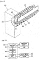
- FIG. 2 is a perspective view of the ice maker in FIG. 2
- FIG. 3 is a sectional view taken along line I-I in FIG. 2
- FIG. 4 is a sectional view taken along line II-II in FIG. 2
- FIG. 5 is a schematic block diagram of a control unit in FIG. 2 .
- the ice maker 100 includes a water supply unit 110 connected to a water source and supplying water, an ice making container 120 having ice making space 122 for receiving water supplied from the water source 110 and making ice, a partitioning plate 130 for partitioning the ice making space 122 of the ice making container 120 into a plurality of unit spaces (C), an a driving unit 140 installed at one side of the ice making container 120 and rotating the ice making container 120 to allow ice to be released from the ice making container 120.
- a water supply unit 110 connected to a water source and supplying water
- an ice making container 120 having ice making space 122 for receiving water supplied from the water source 110 and making ice
- a partitioning plate 130 for partitioning the ice making space 122 of the ice making container 120 into a plurality of unit spaces (C)
- an a driving unit 140 installed at one side of the ice making container 120 and rotating the ice making container 120 to allow ice to be released from the ice making container 120.
- the water supply unit 110 includes a water supply pipe 111 connecting the water source and the ice making space 122 of the ice making container 120, a water supply valve 112 installed in the middle of the water supply pipe 111 to regulate the amount of water supplied (or a water supply amount), and a water supply pump installed at an upper flow side or a lower flow side of the water supply valve 112 to pump water.
- the water supply pump 113 is required to supply uniform water pressure, but not requisite. When the water supply pump 113 is excluded, water may be supplied by using a height difference between the water source and the ice making container 120.
- the water supply pipe 111 may be directly connected to the water source to supply water, or the water supply pipe 111 may be connected to a water tank (not shown) provided in the refrigerating chamber 3 and storing a certain amount of water therein.
- the water tank is a water source.
- a water level sensor may be installed in the ice making container 120 or a flow sensor for detecting the amount of water flow may be installed in the water supply pipe or a water level sensor may be installed in the water tank.
- the water supply valve 112 and the water supply pump 113 may be electrically connected to transmit and receive a signal to a control unit 160.
- the control unit 160 may regulate the water supply amount based on a value detected in real time by the water level sensor or the flow sensor, or an operation time of the water supply valve 112 and the water supply pump 113 may be made into data so as to periodically turn on or off the water supply valve 112 and the water supply pump 113.
- the ice making container 120 includes a container unit 121 having the ice making space 122 to receive water and make ice therein, and a shaft unit 125 formed to be protruded from one side of the container unit 121.
- the container unit 121 has a single ice making space 122 substantially having a shape of a hemispherical container section. However, a slit (not shown) may be formed in a circumferential direction on an inner circumferential surface of the container unit 121 to allow partition walls 132 of the partitioning plate 30 (to be described) to be inserted therein.
- the container unit 121 includes pushers 123 formed to be protruded in a tooth form at one opening end thereof in order to push ice in each of the unit spaces (C) to release the ice.
- the inner circumferential surface of the ice making container 120 constituting the ice making space 122 may be coated with a fluorine material. Of course, the inner circumferential surface of the ice making container 120 may be coated with any other materials such as ceramic, or the like.
- the shaft unit 126 may be formed at the center of the container unit 121 in an axial direction and may be coupled to the driving unit 140 with a decelerator interposed therebetween.
- the partitioning plate 130 includes a fixed part 131 extending in the same direction as the shaft unit 125 of the ice making container 120, having a shaft-like shape, and fixed to the driving unit 140, a plurality of barrier wall parts 132 formed at certain interval along the axial direction from the fixed part 131 toward the ice making container to partition the ice making space 122 into a plurality of unit spaces (C), and a stopper part 133 connecting upper surfaces of the partition wall parts 132 to allow ice cubes in the unit spaces (C) to be released, rather than being rotated along with the ice making container 120 when the ice making container 120 is rotated.
- one end of the fixed part 131 is integrally coupled to a motor housing 141 constituting the driving unit 140 and the other end of the fixing part 131 is rotatably coupled to the center of the container unit 121 of the ice making container 120.
- the partition wall parts 132 are formed to have the same shape, namely, a semi-circular shape, as that of the ice making space 122 when projected in the axial direction.
- the partition wall parts 132 may be formed such that an outer circumferential surface thereof is in contact with an inner circumferential surface of the ice making space 122, in order to reduce a connection area between ice cubs (or ice pieces) to release the ice.
- a water channel 135 having a certain depth is formed at one side of the outer circumferential surface of the partition wall parts 132, specifically, at the lowermost point of the partition wall parts 132, to allow water to move to the unit spaces (C).
- the water channel 135 may be penetratingly formed in the middle of the partition wall parts 132.
- the stopper part 133 may be formed at a portion where a pusher 123 of the ice making container 120 is provided, namely, at a front end portion when the ice making container 120 is rotated.
- the stopper part 133 may be formed to cover the entire upper surface of one side of the partition wall parts 132, or may be formed to be protruded to prevent ice from being rotated along with the ice making container 120 according to circumstances.
- the stopper part 133 may serve to prevent water put in the ice making container 120 from being splashed, it may be formed to be as large as possible.
- the partitioning plate 130 may be coated with a fluorine group like the inner circumferential surface of the ice making container 120.
- the driving unit 140 may include a motor housing 141 fixedly installed in the ice making chamber 51, a driving motor 142 installed in the interior of the motor housing 141 and generating a turning force, and a deceleration gear 143 coupled to the driving motor 142 to decelerate the turning force and deliver the same to the ice making container 120.
- the shaft unit 125 of the ice making container 120 is rotatably coupled to the motor housing 141, and the fixed part 131 of the partitioning plate 130 is fixedly coupled to the motor housing 141.
- a heater made of a heat conductive material such as aluminum to separate ice from the ice making space 122 of the ice making container 120 may be installed on an outer circumferential surface of the ice making container 120.
- the heater 150 may be configured as a line heater in contact with the outer circumferential surface of the ice making container 120.
- the heater 150 may be controlled to interwork with the water supply unit 110. For example, it is determined whether water is being currently supplied to the ice making container 120 to make ice, whether ice making is being performed, or whether ice, after being made, is being released according to the change in the values detected by the water level sensor or the flow sensor, and when it is determined that water is being supplied to make ice or when it is determined that water has been completely supplied and ice is being currently made, the operation of the heater is stopped, and when ice releasing is currently performed after ice making is completed, the operation of the heater 150 may be controlled to start.
- a point in time at which the heater 150 is operated may be determined by detecting the temperature of the ice making container 120 in real time or periodically, or a time which has lapsed after the value of the water level sensor or the flow sensor of the water supply unit 110 was changed may be made into data and the heater may be forcibly operated according to the data value. Namely, whether or not the ice making operation has been completed can be checked by detecting the temperature of the ice making container 120 or through an ice making time.
- a temperature sensor mounted in the ice making container 120
- a certain temperature e.g., -9 C
- the heater 150 may be formed of a conductive polymer, a plate heater with positive thermal coefficient, an aluminum thin film, and other materials such as a heat transfer available material, or the like.
- the heater is attached to the front side of the ice making container 120, although not shown, it may be buried in the interior of the ice making container 120 or provided on an inner circumferential surface of the ice making container 120.
- the ice making container may be configured as a resistor which can generate heat such that at least a portion of the ice making container 120 may serve as a heater to generate heat when electricity is applied thereto.
- the heater 150 may be installed to be spaced apart from the ice making container 120, rather than being in contact with the ice making container 120, so as to be configured as a heat source.
- the heat source includes a light source irradiating light to at least one of ice and the ice making container 120, a magnetron irradiating microwaves to at least one of ice and the ice making container 120.
- the heat sources such as the heater, the light source, or the magnetron directly applies thermal energy to at least one of ice and the ice making container 120 or to the interface therebetween to melt a portion of the interface between ice and the ice making container 120.
- the ice making container 120 when the ice making container 120 is rotated, although the interface between the ice and the ice making container 120 is not entirely thawed, the ice can be separated from the ice making container by the self-weight or the pusher 123 of the ice making container 120.
- the heater 150 and the driving motor 142 may be controlled together by a control unit 160, namely, a microcomputer, electrically connected to the driving motor 142 and the heater 150.
- the control unit 160 includes a detection unit 161 connected to a temperature sensor (not shown) to detect the temperature of the ice making container 120 or a timer (not shown) to detect a time which has lapsed since water was supplied, a determining unit 162 for determining whether or not ice making has been completed by comparing the temperature or time detected by the detection unit 151 with a reference value, and a command unit 163 for controlling an ON/OFF operation of the heater 150 and the operation of the driving motor 142 according to the determination of the determining unit 162.
- FIGS. 6 and 7 An ice supply method in a refrigerator according to an exemplary embodiment of the present invention is shown in FIGS. 6 and 7 .
- the ice maker 100 is turned on to start ice making operation (S1). Then, the water supply unit 110 supplies water to the ice making container 120 (S2). In this case, the water supply amount is detected by using the water level sensor installed at the ice making container 120, the flow sensor installed at the water supply pipe, the water level sensor installed at the water tank, and the like, in real time, and the detected water supply amount is delivered to the microcomputer. Then, the microcomputer compares the received water supply amount with a pre-set water supply amount (S3).
- the microcomputer determines whether or not an appropriate amount of water has been supplied to the ice making container 120 according to the comparison, and when the microcomputer determines that an appropriate amount of water has been supplied to the ice making container 120, the microcomputer shuts off the water supply valve of the water supply unit 110 to prevent water from being supplied to the ice making container any more (S4).
- the water in the ice making container 120 is exposed to cold air supplied to the ice making chamber 51 for more than a certain period of time and frozen (S5).
- the temperature sensor (not shown) detects the temperature of the ice making container periodically or in real time and delivers the detected temperature to the microcomputer.
- the microcomputer compares the received measured temperature with a pre-set temperature (S6).
- the microcomputer determines whether the surface of the water put in the ice making container 110 has been frozen, and when the microcomputer determines that the surface of the water in the ice making container 110 has been frozen, it stops the sequential operations and enters a water releasing step (S7).
- the heater 150 When ice releasing is requested by the user, the heater 150 is operated by the control unit 160, and when the heater 150 is operated, heat is applied to the ice making container 120, melting an outer surface of the ice in contact with the inner circumferential surface of the ice making container 120 (S8 and S9).
- the ice (I) cubes of the unit space C are stopped by the stopper part 133 of the partitioning plate 130, so they cannot be rotated along the ice making container 120 (S10).
- the ice making container 120 is further rotated, the pusher 123 of the ice making container 120, passing between the partition wall parts 132 formed at the opposite side of the stopper part 133 of the partitioning plate 130, pushes the ice (F) cubes of the respective unit spaces (C) by the turning force (F) according to the driving motor 142.
- the ice (I) cubes are separated from the separation wall parts 132 and the stopper part 133 of the partitioning plate 130 to freefall to be discharged to the ice storage container 52 or directly to the dispenser 53 (S1 and S12).
- supply of cold air to the ice making chamber 51 may be stopped to facilitate the ice releasing operation and reduce power applied to the heater 150.
- the operations of the heater 150 and the cutting unit 140 are stopped, the water supply valve 112 is open to supply an appropriate amount of water to the ice making container 120 by the water level sensor, the flow sensor, or the like. This sequential process is repeatedly performed.
- the refrigerator including the ice maker can become slimmer.
- the ice of the ice making container is pushed by an ejector so as to be released, a space for pushing up the ice from the ice making container is required, and in order to store the ice, the ice storage container must be provided at a front side of the ice making container, the area occupied by the ice maker is large over all, having a limitation of making the refrigerator slimmer.
- the ice making container is rotated to allow ice to freefall to be released, there is no need to push up and rotate ice, reducing the ice releasing space, and since the ice storage container is provided to a lower side of the ice making container, the area occupied by the ice maker can be significantly reduced to make the refrigerator or the refrigerator door slimmer.
- the roughness of the inner circumferential surface of the ice making container can be enhanced, and accordingly, when the ice releasing heater is installed at the ice making container, heat can be evenly transferred by the heat releasing heater, effectively performing the heat releasing operation, and the amount of residual water generation can be reduced to prevent ice kept in storage from being entangled.
- the use of an ice releasing heater can be omitted, and in this case, since ice can be released without using a heater, power consumption can be reduced as much and residual water which may be otherwise generated by a heater can be reduced to improve the quality of ice stored in the ice storage container.
- a cover plate 170 may be additionally provided at an upper side of the partitioning plate 130.
- the cover plate 170 may have a shape of a semicircular section concave in the opposite direction to that of the ice making container 120, and a water supply recess and cold air through hole may be formed to be long in a horizontal direction at the center of the upper end of the cover plate 170.
- the cover plate 170 may include an elastic part 172 to allow the cover plate 170 to elastically open when the ice making container 120 is rotated.
- An ice maker is as follows. Namely, in the foregoing exemplary embodiment, the ice releasing heater is installed in the ice making container, but in the present exemplary embodiment, an ice releasing heater is installed to be in contact with partition walls.
- FIG. 10 is a perspective view showing another example of the ice maker of FIG. 1 .
- FIG. 11 is a sectional view taken along line III-III in FIG. 10 .
- FIG. 12 is a rear perspective view of the ice maker of FIG. 10 .
- FIG. 13 is a schematic block diagram of a control unit of FIG. 10 . A detailed description of the same parts in the present exemplary embodiment as those of the ice maker of the foregoing exemplary embodiment will be omitted.
- an ice maker 200 includes a water supply unit 210 connected to a water source and supplying water, an ice making container 120 having an ice making space 222 for receiving water supplied from the water source 210 and making ice, partition walls 230 partitioning the ice making space 222 into a plurality of unit spaces (C), a stopper 240 provided to an opening side of the ice making container 220 and releasing ice from the ice making container, and a driving unit 250 installed at one side of the ice making container 220 and rotating the ice making container 220 to release ice.
- a water supply unit 210 connected to a water source and supplying water
- an ice making container 120 having an ice making space 222 for receiving water supplied from the water source 210 and making ice
- partition walls 230 partitioning the ice making space 222 into a plurality of unit spaces (C)
- a stopper 240 provided to an opening side of the ice making container 220 and releasing ice from the ice making container
- a driving unit 250
- the water supply unit 210 includes a water supply pipe 211 connecting the water source and the ice making container 220, a water supply valve 212 installed in the middle of the water supply pipe 111 to regulate the amount of water supplied (or a water supply amount), and a water supply pump installed at an upper flow side or a lower flow side of the water supply valve 212 to pump water.
- the water supply pump 213 is required to supply uniform water pressure, but not requisite. When the water supply pump 213 is excluded, water may be supplied by using a height difference between the water source and the ice making container 220.
- the ice making container 220 has substantially a shape of a semicircular section and includes a single ice making space 221.
- a coated surface 222 made of a fluorine material may be formed on an inner circumferential surface of the ice making space 221.
- the coated surface may be made of any other materials such as ceramic, or the like.
- blocking film parts 223 made of a material having elasticity such as silicon may be formed at both ends of the opening side of the ice making container 220 in order to prevent water from overflowing at a water supply position of the ice making container 220.
- the plurality of partition walls 230 may be disposed at certain intervals along a lengthwise direction of the ice making container 220 to demarcate the ice making space 221 into a plurality of unit spaces (C).
- the partition walls 230 are formed to have the same shape, namely, a semi-circular shape, as that of the ice making space 122 when projected in the axial direction.
- the partition wall parts 132 may be formed such that an outer circumferential surface thereof is in contact with an inner circumferential surface of the ice making space 122, in order to reduce a connection area between ice cubs (or ice pieces) to release the ice.
- a water channel 231 having a certain depth is formed at one side of the outer circumferential surface of the partition walls 230, specifically, at the lowermost point of the partition walls 230, to allow water to move to the unit spaces (C).
- the water channel 231 may be penetratingly formed in the middle of the partition walls 230.
- the stopper 240 is integrally formed with the partition walls by connecting the upper surfaces of the partition walls 230 in order to release ice cubes of the unit spaces (C) without being rotated along with the ice making container 220 when the ice making container 220 is rotated.
- a coated surface make of a fluorine material may be formed on the surface of the stopper 240, like the inner circumferential surface of the ice making container 220.
- the stopper 240 may be formed at a portion first contacted by ice when the ice making container 220 is rotated.
- the stopper 240 may be formed to cover the entirety of one upper surface of the partition walls 230, or may be formed have protrusions and depressions to prevent ice from being rotated along with the ice making container 220 according to circumstances.
- the stopper 240 is formed to be as large as possible and has a shape of a flat plate such that an end thereof is in contact with the inner circumferential surface of the ice making container 220 in order to serve to prevent water put in the ice making container 220 from being splashed and form a water storage space 241 between an upper surface of the stopper 240 and the inner circumferential surface of the ice making container 220.
- the stopper 240 is formed to be downwardly sloped toward the inner circumferential surface of the ice making container 220 in order to form the water storage space 241 on its upper surface, and a blocking part 242 is formed at an end of an inner side of the stopper 240 and has a certain height in a vertical direction in order to prevent water in the water storage space 241 from flowing into the ice making space 221.
- the driving unit 250 may include a motor housing 251 fixedly installed in the ice making chamber 51, a driving motor 252 installed in the interior of the motor housing 251 and generating a turning force, and a deceleration gear 253 coupled to the driving motor 252 to decelerate the turning force and deliver the same to the ice making container 220.
- a frame 260 fixedly coupled to the refrigerator door 5 is formed to be in contact with or integrally formed at a portion of the upper surface of the partition walls 230, namely, at the opposite side of the stopper 240, and a heater insertion recess 261 may be formed to be long along a lengthwise direction of the ice making container 220 to allow an ice releasing heater 270 to be mounted therein.
- the frame 260 may be made of a material having excellent heat conductivity, such as aluminum, or the like.
- the partitions walls 230 may be made of the same material as that of the frame 260, namely, may be made of an aluminum material having excellent heat conductivity.
- the configuration and operation of the heater 270 and a control unit 280 (See FIG. 12 ) for operating the heater 270 are the same as those of the former exemplary embodiment, so a detailed description thereof will be omitted.
- a cover 290 may be additionally provided at an upper side of the frame 280.
- the cover 280 may have a shape of a semicircular section concave in the opposite direction to that of the ice making container 220, and a water supply groove 291 may be formed to be long in a horizontal direction at the center of the upper end of the cover plate 290.
- the cover 290 may include an elastic part 292 to allow the cover 280 to elastically open when the ice making container 220 is rotated.
- FIGS. 14 and 15 An ice supplying method in a refrigerator according to the present exemplary embodiment is as illustrated in FIGS. 14 and 15 . Since it is similar to that of the former exemplary embodiment, a detailed description thereof will be omitted.
- the ice maker according to the present exemplary embodiment is slightly different in the configuration from the ice maker of the former exemplary embodiment, so there may be a difference in the corresponding operation.
- the heater 270 is operated by the control unit 280, and when the heater is operated 270, heat is applied to the frame 260 and an outer surface of the ice in contact with the partition walls 230 coupled to the frame 260 starts to melt (S8).
- the driving motor 252 is operated by the control unit 280 to rotate the ice making container 220, and in this case, the ice cubes in the unit spaces (C), which are not completely separated from the ice making container 220, are inclined to rotate along the ice making container 220.
- the ice cubes in the unit spaces (C) are stopped by the stopper 240, being restrained from rotating along the ice making container 220, so when the ice making container 220 is further rotated, the ice cubes placed in the ice making container 220 are separated to freefall so as to be discharged to the ice storage container 52 for keeping ice in storage or directly discharged to the dispenser 53 (S12).
- supply of cold air to the ice making chamber 51 may be stopped to facilitate the ice releasing operation and reduce power applied to the heater 133.
- the operations of the heater 133 and the cutting unit 140 are stopped, the water supply valve 112 is open to supply an appropriate amount of water to the ice making container 120 by the water level sensor, the flow sensor, or the like. This sequential process is repeatedly performed.
- the operational effects of the ice maker, the refrigerator having the same, and the method for supplying ice of the refrigerator according to the present exemplary embodiment of the present invention are similar to those of the former exemplary embodiment of the present invention.
- the ice releasing heater for releasing ice from the ice making container is installed on the partitioning plate as a fixed body, the ice making container can be easily driven, facilitating the fabrication and reducing power consumption.
Landscapes
- Engineering & Computer Science (AREA)
- Physics & Mathematics (AREA)
- Mechanical Engineering (AREA)
- Thermal Sciences (AREA)
- General Engineering & Computer Science (AREA)
- Production, Working, Storing, Or Distribution Of Ice (AREA)
- Devices That Are Associated With Refrigeration Equipment (AREA)
Claims (12)
- Machine à glace (100, 200) comprenant :un conteneur de production de glace (120, 220) ayant un compartiment de production de glace (122, 222) pour permettre d'y mettre de l'eau pour produire de la glace ;une plaque de cloisonnement (130) ayant une pluralité de parois de cloisonnement (132) pour délimiter le compartiment de production de glace (122, 222) en une pluralité de compartiments unitaires (C) ;une unité d'entraînement (140, 250) destinée à appliquer une force rotative au conteneur de production de glace (120, 220) pour permettre au conteneur de production de glace (120, 220) de se mettre en rotation par rapport à la plaque de cloisonnement (130) afin de relâcher de la glace du compartiment de production de glace (122, 222) ; etun canal à eau (135, 231) formé à un point le plus inférieur des parois de cloisonnement (132, 230) pour permettre à l'eau de se déplacer jusqu'aux compartiments unitaires (C),dans laquelle la plaque de cloisonnement (130) comprend un arrêt (133, 240) pour arrêter la glace du compartiment de production de glace (122, 222) pour permettre à la glace d'être relâchée depuis le conteneur de production de glace (120, 220),caractérisée en ce quel'arrêt (240) est intégralement formé avec les parois de cloisonnement (230) en reliant les surfaces supérieures des parois de cloisonnement (230),dans laquelle l'arrêt (240) est formé de manière à être incliné vers le bas vers la surface circonférentielle intérieure du conteneur de production de glace (220) afin de former un compartiment de stockage d'eau (241) sur une surface supérieure de l'arrêt (240), etdans laquelle une partie de blocage (242) est formée à une extrémité d'un côté intérieur de l'arrêt (240) et à une certaine hauteur dans une direction verticale afin d'empêcher l'eau dans le compartiment de stockage (241) de s'écouler jusque dans le compartiment de production de glace (221).
- Machine à glace (100) selon la revendication 1, dans laquelle l'arrêt (133) est formé de manière à relier les parois de cloisonnement.
- Machine à glace (100) selon l'une des revendications 1 à 2, dans laquelle un poussoir (123) est formé de manière à être projeté depuis une extrémité ouverte du conteneur de production de glace (120) afin de pousser la glace depuis la plaque de cloisonnement (130) via les parois de cloisonnement (132).
- Machine à glace (100) selon l'une des revendications 1 à 3, dans laquelle le conteneur de production de glace (120) comprend un dispositif chauffant de relâchement de glace (150),
dans laquelle le dispositif chauffant de relâchement de glace (150) est connecté électriquement à l'unité de commande, et l'unité de commande (160) comprend une unité de détection (161) pour détecter la température du conteneur de production de glace (120) ou pour détecter un temps qui s'est écoulé depuis que l'eau a été approvisionnée, une unité de détermination (162) pour déterminer si la production de glace a été ou n'a pas été achevée en comparant la température ou le temps détecté par l'unité de détection (161) à une valeur de référence, et une unité de commande (163) pour commander un fonctionnement MARCHE/ARRÊT du dispositif chauffant (150) selon la détermination de l'unité de détermination (162). - Machine à glace (200) selon l'une des revendications 1 à 3, dans laquelle un dispositif chauffant de relâchement de glace (270) est en contact avec la plaque de cloisonnement,
dans laquelle le dispositif chauffant de relâchement de glace (270) est connecté électriquement à l'unité de commande (280), et l'unité de commande (280) comprend une unité de détection pour détecter la température du conteneur de production de glace ou pour détecter un temps qui s'est écoulé depuis que l'eau a été approvisionnée, une unité de détermination pour déterminer si la production de glace a été ou n'a pas été achevée en comparant la température ou le temps détecté par l'unité de détection à une valeur de référence, et une unité de commande pour commander un fonctionnement MARCHE/ARRÊT du dispositif chauffant (270) selon la détermination de l'unité de détermination. - Machine à glace (200) selon la revendication 1, dans laquelle un couvercle (290) est prévu sur un côté supérieur de l'arrêt (240) afin d'empêcher l'eau introduite dans le conteneur de production de glace (220) de déborder, et
dans laquelle le couvercle (290) comprend une partie élastique (292) permettant au couvercle d'être ouvert élastiquement quand le conteneur de production de glace (220) est mis en rotation. - Réfrigérateur comprenant :un corps principal de réfrigérateur (1) ayant une chambre de production de glace (51) ; etune machine à glace (100, 200) prévue dans la chambre de production de glace (51) du corps principal de réfrigérateur (1),dans laquelle la machine à glace (100, 200) est configurée selon l'une quelconque des revendications 1 à 6.
- Réfrigérateur selon la revendication 7, dans lequel le corps principal de réfrigérateur (1) est délimité en une chambre de congélation (2) et une chambre de réfrigération (3), la chambre de production de glace (51) est prévue sur une porte de réfrigérateur (5) pour ouvrir et fermer la chambre de réfrigération (3), un conteneur de stockage de glace (52) est prévu sur la porte de réfrigérateur (5) ayant la chambre de production de glace (51) afin de garder la glace, séparée de la machine à glace (100), en stockage, et le conteneur de stockage de glace (52) est positionné à l'intérieur de la zone du conteneur de fabrication de glace (120, 220).
- Procédé d'approvisionnement de glace, le procédé comprenant les étapes consistant à :produire (S5) de la glace dans une machine à glace selon l'une quelconque des revendications 1 à 8 ;recevoir (S8) un signal de distribution de glace par un utilisateur ;mettre en rotation (S10) un conteneur de production de glace de la machine à glace ;séparer (S11) la glace provenant de la machine à glace ; etdistribuer (S12) la glace séparée.
- Procédé selon la revendication 9, dans lequel la production de glace comprend les étapes consistant à :approvisionner (S2) de l'eau jusqu'au conteneur de production de glace ;détecter (S3) la température ou la quantité d'eau approvisionnée jusqu'au conteneur de production de glace ; etdéterminer (S3) si la température d'eau et la quantité d'eau détectées ont ou n'ont pas atteint une température d'eau ou une quantité d'eau prédéfinie.
- Procédé selon la revendication 9 ou 10, dans lequel, dans l'étape consistant à séparer (S11) la glace depuis la machine à glace, le conteneur de production de glace de la machine à glace appliquant directement une force à la glace lorsqu'il est mis en rotation.
- Procédé selon l'une des revendications 9 à 11, comprenant en outre l'étape consistant à :
arrêter l'approvisionnement d'air froid au conteneur de production de glace avant de mettre en rotation le conteneur de production de glace.
Applications Claiming Priority (3)
| Application Number | Priority Date | Filing Date | Title |
|---|---|---|---|
| KR1020100016378A KR20110096873A (ko) | 2010-02-23 | 2010-02-23 | 제빙장치 및 이를 구비한 냉장고 및 이 냉장고의 얼음 공급 방법 |
| KR1020100020979A KR101690126B1 (ko) | 2010-03-09 | 2010-03-09 | 제빙장치 및 이를 구비한 냉장고 |
| PCT/KR2011/001239 WO2011105791A2 (fr) | 2010-02-23 | 2011-02-23 | Machine à glaçons, réfrigérateur ayant celle-ci, et procédé de distribution de glaçons de celui-ci |
Publications (3)
| Publication Number | Publication Date |
|---|---|
| EP2539648A2 EP2539648A2 (fr) | 2013-01-02 |
| EP2539648A4 EP2539648A4 (fr) | 2016-03-16 |
| EP2539648B1 true EP2539648B1 (fr) | 2019-05-01 |
Family
ID=44507411
Family Applications (1)
| Application Number | Title | Priority Date | Filing Date |
|---|---|---|---|
| EP11747681.2A Active EP2539648B1 (fr) | 2010-02-23 | 2011-02-23 | Machine à glaçons, réfrigérateur ayant celle-ci, et procédé de distribution de glaçons de celui-ci |
Country Status (4)
| Country | Link |
|---|---|
| US (1) | US20120318003A1 (fr) |
| EP (1) | EP2539648B1 (fr) |
| CN (1) | CN102770727B (fr) |
| WO (1) | WO2011105791A2 (fr) |
Families Citing this family (21)
| Publication number | Priority date | Publication date | Assignee | Title |
|---|---|---|---|---|
| KR20130078531A (ko) | 2011-12-30 | 2013-07-10 | 삼성전자주식회사 | 냉장고 |
| WO2014102042A1 (fr) * | 2012-12-26 | 2014-07-03 | Arcelik Anonim Sirketi | Unité de distribution de glaçons comprenant un moyen de coupe |
| ES2791727T3 (es) * | 2014-02-24 | 2020-11-05 | Lg Electronics Inc | Dispositivo para fabricación de hielo, refrigerador que incluye dispositivo para fabricación de hielo, y método para controlar el refrigerador |
| CN103940184B (zh) * | 2014-04-08 | 2016-11-02 | 河南新飞制冷器具有限公司 | 风冷冰箱用制冰机及其控制方法 |
| KR20160004881A (ko) | 2014-07-04 | 2016-01-13 | 주식회사 대창 | 면상 히터 및 이를 구비하는 제빙기 |
| WO2016003081A1 (fr) * | 2014-07-04 | 2016-01-07 | 주식회사 대창 | Élément chauffant plan et machine à glace le comportant |
| US20160201965A1 (en) * | 2015-01-14 | 2016-07-14 | General Electric Company | Ice makers and refrigeration appliances with ice makers |
| KR20170052235A (ko) * | 2015-11-04 | 2017-05-12 | 삼성전자주식회사 | 제빙기 및 이를 포함하는 냉장고 |
| US9976788B2 (en) | 2016-01-06 | 2018-05-22 | Electrolux Home Products, Inc. | Ice maker with rotating ice tray |
| US20170248357A1 (en) * | 2016-02-29 | 2017-08-31 | General Electric Company | Stand-Alone Ice Making Appliances |
| CN107576116B (zh) * | 2017-08-18 | 2020-09-18 | 广东金佰格制冷设备有限公司 | 一种制冷设备的节能控制系统 |
| US10539354B2 (en) | 2017-12-22 | 2020-01-21 | Electrolux Home Products, Inc. | Direct cooling ice maker |
| US11181309B2 (en) | 2017-12-22 | 2021-11-23 | Electrolux Home Products, Inc. | Direct cooling ice maker |
| KR102432022B1 (ko) * | 2018-01-16 | 2022-08-12 | 삼성전자주식회사 | 제빙장치 |
| US10788252B2 (en) * | 2018-07-19 | 2020-09-29 | Haier Us Appliance Solutions, Inc. | Ice making assembly for a refrigerator appliance |
| US11598566B2 (en) | 2020-04-06 | 2023-03-07 | Electrolux Home Products, Inc. | Revolving ice maker |
| CN112178996A (zh) * | 2020-08-31 | 2021-01-05 | 天津职业技术师范大学(中国职业培训指导教师进修中心) | 一种快速制冰的方法和制冰装置 |
| US11709008B2 (en) | 2020-09-30 | 2023-07-25 | Midea Group Co., Ltd. | Refrigerator with multi-zone ice maker |
| WO2022109237A1 (fr) * | 2020-11-20 | 2022-05-27 | Abstract Ice, Inc. | Dispositifs de mise en forme de produits de glace transparents et procédés associés |
| US20230324097A1 (en) * | 2022-04-11 | 2023-10-12 | Midea Group Co., Ltd. | Refrigerator with a thermally conductive component with heater for ice maker |
| WO2024159832A1 (fr) * | 2023-01-31 | 2024-08-08 | 海信冰箱有限公司 | Réfrigérateur et procédé de commande pour réfrigérateur |
Family Cites Families (11)
| Publication number | Priority date | Publication date | Assignee | Title |
|---|---|---|---|---|
| US2962876A (en) * | 1959-01-07 | 1960-12-06 | Borg Warner | Semi-automatic ice cube maker |
| US3206940A (en) * | 1963-10-22 | 1965-09-21 | Erling B Archer | Automatic ice cube making apparatus |
| US6112540A (en) * | 1998-04-07 | 2000-09-05 | Varity Automotive, Inc. | Ice maker |
| KR20000007728U (ko) * | 1998-10-08 | 2000-05-06 | 전주범 | 냉장고 자동제빙장치의 이빙장치 |
| JP4499569B2 (ja) * | 2002-10-21 | 2010-07-07 | エルジー エレクトロニクス インコーポレイティド | ファンアセンブリを有する製氷機 |
| US7628030B2 (en) * | 2004-10-26 | 2009-12-08 | Whirlpool Corporation | Water spillage management for in the door ice maker |
| JP2007057198A (ja) * | 2005-08-26 | 2007-03-08 | Matsushita Electric Ind Co Ltd | 製氷皿 |
| KR100808171B1 (ko) * | 2005-12-16 | 2008-03-03 | 엘지전자 주식회사 | 제빙장치 및 그 제어방법 |
| EP1865276B1 (fr) * | 2006-06-07 | 2013-09-04 | Whirlpool Corporation | Machine à glaçons |
| KR100863389B1 (ko) * | 2006-08-24 | 2008-10-13 | 엘지전자 주식회사 | 냉장고 및 냉장고의 제빙 장치 |
| JP2008057895A (ja) * | 2006-08-31 | 2008-03-13 | Nidec Sankyo Corp | 製氷装置 |
-
2011
- 2011-02-23 WO PCT/KR2011/001239 patent/WO2011105791A2/fr active Application Filing
- 2011-02-23 US US13/580,694 patent/US20120318003A1/en not_active Abandoned
- 2011-02-23 CN CN201180010691.8A patent/CN102770727B/zh active Active
- 2011-02-23 EP EP11747681.2A patent/EP2539648B1/fr active Active
Non-Patent Citations (1)
| Title |
|---|
| None * |
Also Published As
| Publication number | Publication date |
|---|---|
| CN102770727B (zh) | 2014-11-26 |
| CN102770727A (zh) | 2012-11-07 |
| WO2011105791A2 (fr) | 2011-09-01 |
| EP2539648A2 (fr) | 2013-01-02 |
| US20120318003A1 (en) | 2012-12-20 |
| WO2011105791A3 (fr) | 2012-01-19 |
| EP2539648A4 (fr) | 2016-03-16 |
Similar Documents
| Publication | Publication Date | Title |
|---|---|---|
| EP2539648B1 (fr) | Machine à glaçons, réfrigérateur ayant celle-ci, et procédé de distribution de glaçons de celui-ci | |
| EP2446203B1 (fr) | Machine à glaçons, réfrigérateur ainsi équipé et procédé de fabrication de glaçons correspondant | |
| US10101071B2 (en) | Refrigerator with ice maker | |
| EP2414750B1 (fr) | Technologie de production de glace | |
| JP4224573B2 (ja) | 自動製氷装置 | |
| US8539779B2 (en) | Ice maker, refrigerator having the same, and ice making method thereof | |
| EP3517854B1 (fr) | Réfrigérateur et procédé de commande d'un réfrigérateur | |
| MX2011004116A (es) | Refrigerador. | |
| EP2539647B1 (fr) | Machine à glaçons, réfrigérateur ayant celle-ci, et procédé de distribution de glaçons de celui-ci | |
| EP3517864B1 (fr) | Appareil de fabrication de glaçons et réfrigérateur en étant doté | |
| EP3460361A1 (fr) | Appareil de fabrication de glaçons et réfrigérateur en étant doté | |
| EP3460366B1 (fr) | Appareil de fabrication de glaçons | |
| KR101690126B1 (ko) | 제빙장치 및 이를 구비한 냉장고 | |
| EP3517863B1 (fr) | Procédé de commande d'un réfrigérateur et réfrigérateur correspondant | |
| EP3460362B1 (fr) | Appareil de fabrication de glaçons et réfrigérateur le comprenant | |
| KR20110096873A (ko) | 제빙장치 및 이를 구비한 냉장고 및 이 냉장고의 얼음 공급 방법 | |
| KR100672392B1 (ko) | 제빙 장치 및 이를 이용한 냉각 장치, 그리고 이의 제어방법 | |
| KR101787913B1 (ko) | 아이스 메이커 및 아이스 메이커가 구비된 냉장고 | |
| US20210372682A1 (en) | Refrigerator and controlling method therefor |
Legal Events
| Date | Code | Title | Description |
|---|---|---|---|
| PUAI | Public reference made under article 153(3) epc to a published international application that has entered the european phase |
Free format text: ORIGINAL CODE: 0009012 |
|
| 17P | Request for examination filed |
Effective date: 20120830 |
|
| AK | Designated contracting states |
Kind code of ref document: A2 Designated state(s): AL AT BE BG CH CY CZ DE DK EE ES FI FR GB GR HR HU IE IS IT LI LT LU LV MC MK MT NL NO PL PT RO RS SE SI SK SM TR |
|
| DAX | Request for extension of the european patent (deleted) | ||
| A4 | Supplementary search report drawn up and despatched |
Effective date: 20160215 |
|
| RIC1 | Information provided on ipc code assigned before grant |
Ipc: F25C 5/08 20060101ALI20160209BHEP Ipc: F25C 1/24 20060101AFI20160209BHEP Ipc: F25C 5/02 20060101ALI20160209BHEP Ipc: F25C 5/18 20060101ALI20160209BHEP |
|
| STAA | Information on the status of an ep patent application or granted ep patent |
Free format text: STATUS: EXAMINATION IS IN PROGRESS |
|
| 17Q | First examination report despatched |
Effective date: 20180620 |
|
| GRAP | Despatch of communication of intention to grant a patent |
Free format text: ORIGINAL CODE: EPIDOSNIGR1 |
|
| STAA | Information on the status of an ep patent application or granted ep patent |
Free format text: STATUS: GRANT OF PATENT IS INTENDED |
|
| INTG | Intention to grant announced |
Effective date: 20181120 |
|
| RAP1 | Party data changed (applicant data changed or rights of an application transferred) |
Owner name: LG ELECTRONICS INC. |
|
| GRAS | Grant fee paid |
Free format text: ORIGINAL CODE: EPIDOSNIGR3 |
|
| GRAA | (expected) grant |
Free format text: ORIGINAL CODE: 0009210 |
|
| STAA | Information on the status of an ep patent application or granted ep patent |
Free format text: STATUS: THE PATENT HAS BEEN GRANTED |
|
| AK | Designated contracting states |
Kind code of ref document: B1 Designated state(s): AL AT BE BG CH CY CZ DE DK EE ES FI FR GB GR HR HU IE IS IT LI LT LU LV MC MK MT NL NO PL PT RO RS SE SI SK SM TR |
|
| REG | Reference to a national code |
Ref country code: GB Ref legal event code: FG4D |
|
| REG | Reference to a national code |
Ref country code: CH Ref legal event code: EP Ref country code: AT Ref legal event code: REF Ref document number: 1127481 Country of ref document: AT Kind code of ref document: T Effective date: 20190515 |
|
| REG | Reference to a national code |
Ref country code: DE Ref legal event code: R096 Ref document number: 602011058515 Country of ref document: DE |
|
| REG | Reference to a national code |
Ref country code: IE Ref legal event code: FG4D |
|
| REG | Reference to a national code |
Ref country code: NL Ref legal event code: MP Effective date: 20190501 |
|
| REG | Reference to a national code |
Ref country code: LT Ref legal event code: MG4D |
|
| PG25 | Lapsed in a contracting state [announced via postgrant information from national office to epo] |
Ref country code: ES Free format text: LAPSE BECAUSE OF FAILURE TO SUBMIT A TRANSLATION OF THE DESCRIPTION OR TO PAY THE FEE WITHIN THE PRESCRIBED TIME-LIMIT Effective date: 20190501 Ref country code: NL Free format text: LAPSE BECAUSE OF FAILURE TO SUBMIT A TRANSLATION OF THE DESCRIPTION OR TO PAY THE FEE WITHIN THE PRESCRIBED TIME-LIMIT Effective date: 20190501 Ref country code: HR Free format text: LAPSE BECAUSE OF FAILURE TO SUBMIT A TRANSLATION OF THE DESCRIPTION OR TO PAY THE FEE WITHIN THE PRESCRIBED TIME-LIMIT Effective date: 20190501 Ref country code: LT Free format text: LAPSE BECAUSE OF FAILURE TO SUBMIT A TRANSLATION OF THE DESCRIPTION OR TO PAY THE FEE WITHIN THE PRESCRIBED TIME-LIMIT Effective date: 20190501 Ref country code: PT Free format text: LAPSE BECAUSE OF FAILURE TO SUBMIT A TRANSLATION OF THE DESCRIPTION OR TO PAY THE FEE WITHIN THE PRESCRIBED TIME-LIMIT Effective date: 20190901 Ref country code: NO Free format text: LAPSE BECAUSE OF FAILURE TO SUBMIT A TRANSLATION OF THE DESCRIPTION OR TO PAY THE FEE WITHIN THE PRESCRIBED TIME-LIMIT Effective date: 20190801 Ref country code: FI Free format text: LAPSE BECAUSE OF FAILURE TO SUBMIT A TRANSLATION OF THE DESCRIPTION OR TO PAY THE FEE WITHIN THE PRESCRIBED TIME-LIMIT Effective date: 20190501 Ref country code: SE Free format text: LAPSE BECAUSE OF FAILURE TO SUBMIT A TRANSLATION OF THE DESCRIPTION OR TO PAY THE FEE WITHIN THE PRESCRIBED TIME-LIMIT Effective date: 20190501 Ref country code: AL Free format text: LAPSE BECAUSE OF FAILURE TO SUBMIT A TRANSLATION OF THE DESCRIPTION OR TO PAY THE FEE WITHIN THE PRESCRIBED TIME-LIMIT Effective date: 20190501 |
|
| PG25 | Lapsed in a contracting state [announced via postgrant information from national office to epo] |
Ref country code: LV Free format text: LAPSE BECAUSE OF FAILURE TO SUBMIT A TRANSLATION OF THE DESCRIPTION OR TO PAY THE FEE WITHIN THE PRESCRIBED TIME-LIMIT Effective date: 20190501 Ref country code: BG Free format text: LAPSE BECAUSE OF FAILURE TO SUBMIT A TRANSLATION OF THE DESCRIPTION OR TO PAY THE FEE WITHIN THE PRESCRIBED TIME-LIMIT Effective date: 20190801 Ref country code: GR Free format text: LAPSE BECAUSE OF FAILURE TO SUBMIT A TRANSLATION OF THE DESCRIPTION OR TO PAY THE FEE WITHIN THE PRESCRIBED TIME-LIMIT Effective date: 20190802 Ref country code: RS Free format text: LAPSE BECAUSE OF FAILURE TO SUBMIT A TRANSLATION OF THE DESCRIPTION OR TO PAY THE FEE WITHIN THE PRESCRIBED TIME-LIMIT Effective date: 20190501 |
|
| REG | Reference to a national code |
Ref country code: AT Ref legal event code: MK05 Ref document number: 1127481 Country of ref document: AT Kind code of ref document: T Effective date: 20190501 |
|
| PG25 | Lapsed in a contracting state [announced via postgrant information from national office to epo] |
Ref country code: IS Free format text: LAPSE BECAUSE OF FAILURE TO SUBMIT A TRANSLATION OF THE DESCRIPTION OR TO PAY THE FEE WITHIN THE PRESCRIBED TIME-LIMIT Effective date: 20190901 |
|
| PG25 | Lapsed in a contracting state [announced via postgrant information from national office to epo] |
Ref country code: CZ Free format text: LAPSE BECAUSE OF FAILURE TO SUBMIT A TRANSLATION OF THE DESCRIPTION OR TO PAY THE FEE WITHIN THE PRESCRIBED TIME-LIMIT Effective date: 20190501 Ref country code: RO Free format text: LAPSE BECAUSE OF FAILURE TO SUBMIT A TRANSLATION OF THE DESCRIPTION OR TO PAY THE FEE WITHIN THE PRESCRIBED TIME-LIMIT Effective date: 20190501 Ref country code: EE Free format text: LAPSE BECAUSE OF FAILURE TO SUBMIT A TRANSLATION OF THE DESCRIPTION OR TO PAY THE FEE WITHIN THE PRESCRIBED TIME-LIMIT Effective date: 20190501 Ref country code: AT Free format text: LAPSE BECAUSE OF FAILURE TO SUBMIT A TRANSLATION OF THE DESCRIPTION OR TO PAY THE FEE WITHIN THE PRESCRIBED TIME-LIMIT Effective date: 20190501 Ref country code: SK Free format text: LAPSE BECAUSE OF FAILURE TO SUBMIT A TRANSLATION OF THE DESCRIPTION OR TO PAY THE FEE WITHIN THE PRESCRIBED TIME-LIMIT Effective date: 20190501 Ref country code: DK Free format text: LAPSE BECAUSE OF FAILURE TO SUBMIT A TRANSLATION OF THE DESCRIPTION OR TO PAY THE FEE WITHIN THE PRESCRIBED TIME-LIMIT Effective date: 20190501 |
|
| REG | Reference to a national code |
Ref country code: DE Ref legal event code: R097 Ref document number: 602011058515 Country of ref document: DE |
|
| PG25 | Lapsed in a contracting state [announced via postgrant information from national office to epo] |
Ref country code: IT Free format text: LAPSE BECAUSE OF FAILURE TO SUBMIT A TRANSLATION OF THE DESCRIPTION OR TO PAY THE FEE WITHIN THE PRESCRIBED TIME-LIMIT Effective date: 20190501 Ref country code: SM Free format text: LAPSE BECAUSE OF FAILURE TO SUBMIT A TRANSLATION OF THE DESCRIPTION OR TO PAY THE FEE WITHIN THE PRESCRIBED TIME-LIMIT Effective date: 20190501 |
|
| PLBE | No opposition filed within time limit |
Free format text: ORIGINAL CODE: 0009261 |
|
| STAA | Information on the status of an ep patent application or granted ep patent |
Free format text: STATUS: NO OPPOSITION FILED WITHIN TIME LIMIT |
|
| PG25 | Lapsed in a contracting state [announced via postgrant information from national office to epo] |
Ref country code: TR Free format text: LAPSE BECAUSE OF FAILURE TO SUBMIT A TRANSLATION OF THE DESCRIPTION OR TO PAY THE FEE WITHIN THE PRESCRIBED TIME-LIMIT Effective date: 20190501 |
|
| 26N | No opposition filed |
Effective date: 20200204 |
|
| PG25 | Lapsed in a contracting state [announced via postgrant information from national office to epo] |
Ref country code: PL Free format text: LAPSE BECAUSE OF FAILURE TO SUBMIT A TRANSLATION OF THE DESCRIPTION OR TO PAY THE FEE WITHIN THE PRESCRIBED TIME-LIMIT Effective date: 20190501 |
|
| PG25 | Lapsed in a contracting state [announced via postgrant information from national office to epo] |
Ref country code: SI Free format text: LAPSE BECAUSE OF FAILURE TO SUBMIT A TRANSLATION OF THE DESCRIPTION OR TO PAY THE FEE WITHIN THE PRESCRIBED TIME-LIMIT Effective date: 20190501 |
|
| REG | Reference to a national code |
Ref country code: CH Ref legal event code: PL |
|
| GBPC | Gb: european patent ceased through non-payment of renewal fee |
Effective date: 20200223 |
|
| REG | Reference to a national code |
Ref country code: BE Ref legal event code: MM Effective date: 20200229 |
|
| PG25 | Lapsed in a contracting state [announced via postgrant information from national office to epo] |
Ref country code: LU Free format text: LAPSE BECAUSE OF NON-PAYMENT OF DUE FEES Effective date: 20200223 Ref country code: MC Free format text: LAPSE BECAUSE OF FAILURE TO SUBMIT A TRANSLATION OF THE DESCRIPTION OR TO PAY THE FEE WITHIN THE PRESCRIBED TIME-LIMIT Effective date: 20190501 |
|
| PG25 | Lapsed in a contracting state [announced via postgrant information from national office to epo] |
Ref country code: CH Free format text: LAPSE BECAUSE OF NON-PAYMENT OF DUE FEES Effective date: 20200229 Ref country code: LI Free format text: LAPSE BECAUSE OF NON-PAYMENT OF DUE FEES Effective date: 20200229 |
|
| PG25 | Lapsed in a contracting state [announced via postgrant information from national office to epo] |
Ref country code: FR Free format text: LAPSE BECAUSE OF NON-PAYMENT OF DUE FEES Effective date: 20200229 Ref country code: GB Free format text: LAPSE BECAUSE OF NON-PAYMENT OF DUE FEES Effective date: 20200223 Ref country code: IE Free format text: LAPSE BECAUSE OF NON-PAYMENT OF DUE FEES Effective date: 20200223 |
|
| PG25 | Lapsed in a contracting state [announced via postgrant information from national office to epo] |
Ref country code: BE Free format text: LAPSE BECAUSE OF NON-PAYMENT OF DUE FEES Effective date: 20200229 |
|
| PG25 | Lapsed in a contracting state [announced via postgrant information from national office to epo] |
Ref country code: MT Free format text: LAPSE BECAUSE OF FAILURE TO SUBMIT A TRANSLATION OF THE DESCRIPTION OR TO PAY THE FEE WITHIN THE PRESCRIBED TIME-LIMIT Effective date: 20190501 Ref country code: CY Free format text: LAPSE BECAUSE OF FAILURE TO SUBMIT A TRANSLATION OF THE DESCRIPTION OR TO PAY THE FEE WITHIN THE PRESCRIBED TIME-LIMIT Effective date: 20190501 |
|
| PG25 | Lapsed in a contracting state [announced via postgrant information from national office to epo] |
Ref country code: MK Free format text: LAPSE BECAUSE OF FAILURE TO SUBMIT A TRANSLATION OF THE DESCRIPTION OR TO PAY THE FEE WITHIN THE PRESCRIBED TIME-LIMIT Effective date: 20190501 |
|
| PGFP | Annual fee paid to national office [announced via postgrant information from national office to epo] |
Ref country code: DE Payment date: 20240105 Year of fee payment: 14 |