EP2539604B1 - Gas spring with temperature compensation - Google Patents
Gas spring with temperature compensation Download PDFInfo
- Publication number
- EP2539604B1 EP2539604B1 EP11747795.0A EP11747795A EP2539604B1 EP 2539604 B1 EP2539604 B1 EP 2539604B1 EP 11747795 A EP11747795 A EP 11747795A EP 2539604 B1 EP2539604 B1 EP 2539604B1
- Authority
- EP
- European Patent Office
- Prior art keywords
- piston
- gas spring
- liquid
- cylinder
- valve
- Prior art date
- Legal status (The legal status is an assumption and is not a legal conclusion. Google has not performed a legal analysis and makes no representation as to the accuracy of the status listed.)
- Active
Links
Images

Classifications
-
- F—MECHANICAL ENGINEERING; LIGHTING; HEATING; WEAPONS; BLASTING
- F16—ENGINEERING ELEMENTS AND UNITS; GENERAL MEASURES FOR PRODUCING AND MAINTAINING EFFECTIVE FUNCTIONING OF MACHINES OR INSTALLATIONS; THERMAL INSULATION IN GENERAL
- F16F—SPRINGS; SHOCK-ABSORBERS; MEANS FOR DAMPING VIBRATION
- F16F9/00—Springs, vibration-dampers, shock-absorbers, or similarly-constructed movement-dampers using a fluid or the equivalent as damping medium
- F16F9/06—Springs, vibration-dampers, shock-absorbers, or similarly-constructed movement-dampers using a fluid or the equivalent as damping medium using both gas and liquid
- F16F9/066—Units characterised by the partition, baffle or like element
- F16F9/067—Partitions of the piston type, e.g. sliding pistons
-
- F—MECHANICAL ENGINEERING; LIGHTING; HEATING; WEAPONS; BLASTING
- F16—ENGINEERING ELEMENTS AND UNITS; GENERAL MEASURES FOR PRODUCING AND MAINTAINING EFFECTIVE FUNCTIONING OF MACHINES OR INSTALLATIONS; THERMAL INSULATION IN GENERAL
- F16F—SPRINGS; SHOCK-ABSORBERS; MEANS FOR DAMPING VIBRATION
- F16F9/00—Springs, vibration-dampers, shock-absorbers, or similarly-constructed movement-dampers using a fluid or the equivalent as damping medium
- F16F9/06—Springs, vibration-dampers, shock-absorbers, or similarly-constructed movement-dampers using a fluid or the equivalent as damping medium using both gas and liquid
- F16F9/064—Units characterised by the location or shape of the expansion chamber
-
- F—MECHANICAL ENGINEERING; LIGHTING; HEATING; WEAPONS; BLASTING
- F16—ENGINEERING ELEMENTS AND UNITS; GENERAL MEASURES FOR PRODUCING AND MAINTAINING EFFECTIVE FUNCTIONING OF MACHINES OR INSTALLATIONS; THERMAL INSULATION IN GENERAL
- F16F—SPRINGS; SHOCK-ABSORBERS; MEANS FOR DAMPING VIBRATION
- F16F9/00—Springs, vibration-dampers, shock-absorbers, or similarly-constructed movement-dampers using a fluid or the equivalent as damping medium
- F16F9/32—Details
- F16F9/50—Special means providing automatic damping adjustment, i.e. self-adjustment of damping by particular sliding movements of a valve element, other than flexions or displacement of valve discs; Special means providing self-adjustment of spring characteristics
- F16F9/52—Special means providing automatic damping adjustment, i.e. self-adjustment of damping by particular sliding movements of a valve element, other than flexions or displacement of valve discs; Special means providing self-adjustment of spring characteristics in case of change of temperature
-
- F—MECHANICAL ENGINEERING; LIGHTING; HEATING; WEAPONS; BLASTING
- F16—ENGINEERING ELEMENTS AND UNITS; GENERAL MEASURES FOR PRODUCING AND MAINTAINING EFFECTIVE FUNCTIONING OF MACHINES OR INSTALLATIONS; THERMAL INSULATION IN GENERAL
- F16F—SPRINGS; SHOCK-ABSORBERS; MEANS FOR DAMPING VIBRATION
- F16F2230/00—Purpose; Design features
- F16F2230/0047—Measuring, indicating
Definitions
- the present document relates to a gas spring. More specifically, the document relates to a gas spring with oil damping intended for the suspension system of a vehicle.
- Gas springs are used for suspension purposes in a large number of vehicles ranging from snowmobiles to large industrial trucks. Quite often the gas springs are provided with oil damping.
- the spring effect of a gas spring is based on the compression of gas, the pressure of the gas varying as a function of the compression.
- Gas springs usually comprise a cylinder which is closed at one end and in which gas is contained.
- a piston connected to a piston rod is movably arranged in the cylinder.
- the piston rod and the cylinder are mounted between two parts of the vehicle between which a spring action is desirable.
- US3944197 A discloses a hydropneumatic suspension device.
- DE3106766 A1 discloses a hydraulic shock absorber for a motor vehicle.
- US3944197 is considered as the closest prior art and discloses a gas spring system comprising a first part which defines a cylinder, which comprises a longitudinal axis and which is closed at a first end along the longitudinal axis, a piston which is arranged to be movable in the cylinder along the longitudinal axis, a piston rod which is connected to the piston and projects out through a second end of the cylinder, a separating piston, which is arranged to be movable in the cylinder along the longitudinal axis between the piston and the first end, gas which is contained in the cylinder between the separating piston and the first end, and liquid which is contained between the separating piston and the piston, wherein the gas spring system comprises an expansion chamber for the liquid, wherein the gas spring system comprises a pressure regulating device, which is adapted to control the liquid transport between the cylinder and the expansion chamber in dependence of the temperature, thereby keeping the force characteristics of the gas spring substantially independent of the
- the variation of the spring force in dependence of the gas temperature as described above may be acceptable as long as it is not too great. However, great variations in the spring force are undesirable as they will affect the behaviour of the vehicle on which the gas spring is mounted.
- One object is to provide a gas spring which at least reduces the problems stated above.
- a further object is to provide a gas spring which at least reduces the problem that the spring force varies as a function of the temperature.
- a gas spring system as defined in the appended claims, comprising a first part which defines a cylinder, which comprises a longitudinal axis and which is closed at a first end along the longitudinal axis.
- the gas spring further comprises a piston which is arranged to be movable in the cylinder along the longitudinal axis, a piston rod which is connected to the piston and which projects out through a second end of the cylinder, a separating piston which is arranged to be movable in the cylinder along the longitudinal axis between the piston and the first end.
- the gas spring comprises gas, which is contained in the cylinder between the separating piston and the first end, and liquid, which is contained between the separating piston and the piston.
- the gas spring is characterised in that it also comprises an expansion chamber for the liquid and a pressure regulating device, which is adapted to control the liquid transport between the cylinder and the expansion chamber in dependence of the temperature, thereby keeping the force characteristics of the gas spring substantially independent of the temperature.
- gas spring system is meant a gas spring with all the functional components integrated therein or a system comprising a gas spring and one or more external parts which cooperate with said gas spring.
- liquid will be conducted away from the cylinder when the gas spring is hot. This will lower the pressure in the cylinder and will thus reduce the spring force exerted by the gas.
- Liquid transport between the cylinder and the expansion chamber can occur in many different ways, but preferably occurs by way of the pressure difference between the cylinder and the expansion chamber, which pressure difference serves as the driving force.
- liquid is an oil, but the use of liquids other than oil is not excluded.
- the pressure regulating device comprises a measuring liquid chamber, which contains measuring liquid, and a pressure tube with a longitudinal axis in which a pressure spindle is movably arranged, the position of the pressure spindle in the pressure tube being dependent on the volume of the measuring liquid and the liquid transport between the cylinder and the expansion chamber being adapted to be controlled by the position of the pressure spindle.
- the position of the pressure spindle is used to control valves which allow a flow to or from the expansion chamber. Since the volume of the measuring liquid varies with the temperature, the position of the pressure spindle will change with the temperature.
- the measuring liquid is preferably a measuring oil, although the use of other measuring liquids is not excluded.
- the measuring liquid chamber is arranged in the piston rod. This is a space-saving arrangement of the measuring liquid chamber, which thus does not take up any space on the outside of the gas spring. Naturally, it is possible to position the measuring liquid chamber on the outside of the gas spring, in which case the transport of liquid between the measuring liquid chamber and the cylinder will occur through tubes. When the liquid has been transferred to the piston rod it no longer affects the spring force of the gas spring.
- the piston rod comprises a piston rod cylinder, the measuring liquid chamber being arranged in a measuring liquid piston, which is movably arranged in the cylinder inside the piston rod.
- gas is contained behind the measuring liquid piston, such that the measuring liquid piston is subjected to a force acting in the direction of the piston.
- the measuring liquid chamber is arranged in a measuring liquid piston, the expansion chamber can be arranged between the measuring liquid piston and the piston, the size of the expansion chamber being dependent on the position of the measuring liquid piston relative to the piston.
- the measuring liquid piston and thus also the liquid in the expansion chamber, will be subjected to a pressure produced by the gas pressure behind the measuring liquid piston.
- the pressure regulating device comprises a valve mechanism which is fixedly arranged relative to the piston, said valve mechanism comprising a regulating space, which is coaxial with the pressure tube and in which the pressure spindle is movably arranged. Consequently, the pressure spindle is guided by both the pressure tube and the regulating space. The position of the pressure spindle in the valve mechanism controls the flow of liquid between the expansion chamber and the measuring liquid chamber.
- the valve mechanism comprises a first liquid line for conducting liquid from the cylinder to the expansion chamber, a first valve which is arranged in the first liquid line for controlling the liquid flow through the first liquid line, a second liquid line for conducting liquid to the cylinder from the expansion chamber, and a second valve which is arranged in the second liquid line for controlling the liquid flow through the second liquid line, the first valve and the second valve being controlled by the axial position of the pressure spindle relative to the valve mechanism.
- not more than one of the valves is open for each axial position of the pressure spindle. In this way, the problem that the flow resistance varies for the same direction of flow can be avoided. If no pressure regulation is required both valves can be closed.
- valves are combined with the check valves, which ensure that the fluid can flow in only one direction in each liquid line.
- Both the first valve and the second valve can comprise a ball, a valve seat and a spring which is adapted to force the ball against the valve seat, the valves being adapted to be opened by the balls being forced away from the valve seats, the pressure spindle comprising bevelled portions for each of the valves and the pressure spindle and the valves being arranged such that each of the valves is closed when the associated bevelled portion is positioned in front of the valve and is open when the bevelled portion is positioned at a distance from the valve and the pressure spindle thus forces the associated ball away from the valve seat.
- valve mechanism is realised in a simple manner.
- the valves may of course be realised also in other ways.
- a gas spring system as defined in the appended claims is provided comprising a measuring liquid chamber arranged externally of the gas spring.
- the external measuring liquid chamber can communicate with a measuring liquid chamber arranged in the piston rod.
- a gas spring system comprising an expansion chamber arranged externally of the gas spring.
- a gas spring system comprising a pressure regulating unit, which is in fluid communication with the cylinder and which is arranged outside the piston rod.
- a motor vehicle as defined in the appended claims comprising a gas spring system according to the first aspect is provided.
- a motor vehicle equipped with a gas spring system according to the first aspect will have road-holding properties which to a lesser extent are dependent on the atmospheric temperature than motor vehicles according to prior art.
- a counterbalancing arrangement for counterbalancing two mutually movable parts as defined in the appended claims, which is adapted to counteract the gravitational force of at least one of said movable parts, the counterbalancing arrangement comprising a gas spring system according to the above, which acts between said movable parts.
- the system disclosed in WO 2010/098717 A1 can be further improved by the fact that variation in the characteristics of the gas springs included in the counterbalancing system, which springs are influenced by factors in the physical environment such as temperature fluctuations, can be reduced in the event of changes in the ambient temperature.
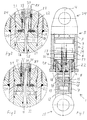
- Fig. 1 is a schematic view of a gas spring 1 according to the invention.
- the gas spring 1 comprises a first part 2, which defines a cylinder 3 in which a gas is contained, and a longitudinal axis 4.
- the cylinder is closed at a first end 5.
- the gas spring 1 further comprises a piston 6, which is arranged to be movable in the cylinder 3 along the longitudinal axis 4, and a piston rod 7, which is connected to the piston 6 and projects out through a second end 8 of the cylinder.
- the gas spring also comprises a separating piston 9, which is arranged to be movable in the cylinder 3 along the longitudinal axis 4 between the piston 6 and the first end 5.
- gas is contained in the cylinder 3 between the separating piston 9 and the first end 5 and liquid is contained between the separating piston 9 and the piston 6.
- the gas spring further comprises an expansion chamber 10 and a pressure regulating device, which is adapted to control the liquid transport between the cylinder and the expansion chamber 10 in dependence of the temperature, thereby keeping the force characteristics of the gas spring 1 substantially independent of the temperature.
- the pressure regulating device in the embodiment shown in Fig. 1 comprises a measuring liquid piston 11, which is arranged to be movable in a piston rod cylinder 12 along the longitudinal axis 4, which piston rod cylinder 12 in turn is arranged in the piston rod 7.
- a measuring liquid chamber 13 is arranged in the measuring liquid piston 11, in which measuring liquid chamber measuring liquid is contained. Behind the measuring liquid piston 11, gas is contained which forces the measuring liquid piston 11 towards the piston 6.
- the measuring liquid piston 11 comprises a pressure tube 14, through which pressure tube 14 measuring liquid is adapted to flow during expansion of the measuring liquid.
- the pressure tube 14 is arranged in parallel with the longitudinal axis 4 and coincides in the embodiment shown with the longitudinal axis 4.
- a pressure spindle 15 is arranged in the pressure tube 14.
- the pressure regulating device further comprises a valve mechanism 16 which is fixedly arranged relative to the piston 6.
- a valve mechanism 16 which is fixedly arranged relative to the piston 6.
- a regulating space 17 which is coaxial with the pressure tube 14 and in which the pressure spindle 15 is movably arranged.
- the bottom of the regulating space 17 is in communication with the expansion chamber 10 such that the pressure spindle on one side is subjected to a pressure corresponding the pressure in the expansion chamber 10 and, on the other side, is subjected to a pressure corresponding to the pressure in the measuring liquid chamber 13.
- the valve mechanism 16 comprises a first liquid line 18 for conducting liquid from the space between the piston 6 and the separating piston 9 to the expansion chamber 10 and a second liquid line 19 for conducting liquid to the space between the piston 6 and the separating piston 9 from the expansion chamber 10.
- the first liquid line 18 comprises a first valve 20 and a first check valve 21.
- the second liquid line 19 comprises a second valve 22 and a second check valve 23.
- the valves 20, 22 and the check valves 21, 23 are shown in greater detail in Fig. 2 and Fig. 3 .
- the gas spring comprises a first mounting element 34 in the first part 2 and a second mounting element 35 in the piston rod 7.
- Fig. 2 is an enlarged view of part of the pressure regulating device of the gas spring 1 in a first position.
- the first valve 20 comprises a first valve seat 24 and a first ball 25, which is forced against the first valve seat 24 by means of a spring 26.
- the second valve 22 comprises in corresponding manner a second valve seat 27 and a second ball 28, which is forced against the second valve seat 27 by means of a spring 29.
- the pressure spindle 15 comprises a first bevelled portion 30, which is oriented towards the first valve 20, and a second bevelled portion 31, which is oriented towards the second valve 22.
- a first auxiliary ball 32 is arranged between the pressure spindle 15 and the first ball 25.
- a second auxiliary ball 33 is arranged between the pressure spindle 15 and the second ball 28.
- the first bevelled portion 30 is positioned in front of the first valve 20 and the first ball 25 rests on the first valve seat 24, thereby keeping the first valve 20 closed.
- the second bevelled portion 31 is not positioned in front of the second valve 22.
- Fig. 3 is an enlarged view of part of the pressure regulating device of the gas spring 1 in a second position.
- the second bevelled portion 31 is positioned in front of the second valve 22, thereby keeping it closed.
- the pressure spindle 15 forces the first auxiliary ball 32, and in turn the first ball 25, inwards, thereby keeping the first valve 20 open.
- the gas spring need not necessarily have a circular-cylindrical cylinder. It is of course conceivable to have cylinders of other shapes, such as an oval cylinder.
- expansion chamber it is not necessary for the expansion chamber to be arranged in the piston rod.
- the expansion chamber can be arranged in a separate part outside the cylinder and the piston rod.
- liquid is preferably meant an oil and a measuring oil, respectively.
- a gas spring 1' comprising an external pressure regulating device 60, which is arranged in a casing 62 and communicates via a conduit 61 (tube, pipe) with the liquid-filled chamber of the gas spring.
- the external pressure regulating device 60 can be arranged externally of the piston/piston rod, as a part which is completely separated from the gas spring, or as a part which is fully or partially integrated with, for example, the cylinder casing.
- the separate casing 62 has a measuring liquid piston 11', which is displaceable inside the casing 62 and which accommodates the measuring liquid chamber 13'. In a space 12' gas is contained which forces the measuring liquid piston 11' towards the expansion chamber 10'.
- the pressure spindle 15' acts between the measuring liquid chamber 13' and the pressure regulating device 21'.
- the pressure regulating device is in communication with the liquid-filled chamber of the gas spring via the lines 61, 18', 19'.
- only the measuring liquid chamber 13, 13' is arranged at least partly outside the gas spring.
- the external measuring liquid chamber and/or expansion chamber described above is/are arranged in such a manner that their sensitivity to variations in the ambient temperature is optimized.
- the size of the internal measuring liquid chamber and/or expansion chamber can be reduced or said chamber or chambers can be eliminated altogether.
- gas spring and the gas spring system described above can be used in a counterbalancing arrangement 50 intended, for instance, for an industrial robot or a derrick boom, as shown in Fig. 5 .
- a gas spring 51 or a gas spring system can be arranged to act between two mutually movable parts 52, 53 in order to compensate, for instance, for the dead weight of one or both of the parts.
Landscapes
- Engineering & Computer Science (AREA)
- General Engineering & Computer Science (AREA)
- Mechanical Engineering (AREA)
- Fluid-Damping Devices (AREA)
Description
- The present document relates to a gas spring. More specifically, the document relates to a gas spring with oil damping intended for the suspension system of a vehicle.
- Gas springs are used for suspension purposes in a large number of vehicles ranging from snowmobiles to large industrial trucks. Quite often the gas springs are provided with oil damping. The spring effect of a gas spring is based on the compression of gas, the pressure of the gas varying as a function of the compression. Gas springs usually comprise a cylinder which is closed at one end and in which gas is contained. A piston connected to a piston rod is movably arranged in the cylinder. The piston rod and the cylinder are mounted between two parts of the vehicle between which a spring action is desirable. When the spring is being used or when the ambient temperature rises, the temperature of the gas in the cylinder increases, which creates increased pressure on the gas and greater force is thus exerted on the piston. In the case where the gas spring also contains oil, which is the case in a gas spring with oil damping, also the expansion of the oil will contribute to the pressure increase. Correspondingly, a reduction of the temperature of the gas and the oil will result in reduced pressure in the gas and less force will thus be exerted on the piston.
-
US3944197 A discloses a hydropneumatic suspension device. -
DE3106766 A1 discloses a hydraulic shock absorber for a motor vehicle.US3944197 is considered as the closest prior art and discloses a gas spring system comprising a first part which defines a cylinder, which comprises a longitudinal axis and which is closed at a first end along the longitudinal axis, a piston which is arranged to be movable in the cylinder along the longitudinal axis, a piston rod which is connected to the piston and projects out through a second end of the cylinder, a separating piston, which is arranged to be movable in the cylinder along the longitudinal axis between the piston and the first end, gas which is contained in the cylinder between the separating piston and the first end, and liquid which is contained between the separating piston and the piston, wherein the gas spring system comprises an expansion chamber for the liquid, wherein the gas spring system comprises a pressure regulating device, which is adapted to control the liquid transport between the cylinder and the expansion chamber in dependence of the temperature, thereby keeping the force characteristics of the gas spring substantially independent of the temperature, wherein the pressure regulating device comprises a measuring liquid chamber, which contains measuring liquid, and a pressure tube in which a pressure spindle is movably arranged, the position of the pressure spindle in the pressure tube being dependent on the volume of the measuring liquid and the liquid transport between the cylinder and the expansion chamber being adapted to be controlled by the position of the pressure spindle, the measuring liquid chamber is arranged in the piston rod, and the piston rod comprises a piston rod cylinder. - The variation of the spring force in dependence of the gas temperature as described above may be acceptable as long as it is not too great. However, great variations in the spring force are undesirable as they will affect the behaviour of the vehicle on which the gas spring is mounted.
- One object is to provide a gas spring which at least reduces the problems stated above.
- A further object is to provide a gas spring which at least reduces the problem that the spring force varies as a function of the temperature.
- The invention is defined by the appended independent claims. Embodiments of the invention will be apparent from the dependent claims, from the following description and from the appended drawings.
- According to a first aspect a gas spring system as defined in the appended claims is provided, comprising a first part which defines a cylinder, which comprises a longitudinal axis and which is closed at a first end along the longitudinal axis. The gas spring further comprises a piston which is arranged to be movable in the cylinder along the longitudinal axis, a piston rod which is connected to the piston and which projects out through a second end of the cylinder, a separating piston which is arranged to be movable in the cylinder along the longitudinal axis between the piston and the first end. Moreover, the gas spring comprises gas, which is contained in the cylinder between the separating piston and the first end, and liquid, which is contained between the separating piston and the piston. The gas spring is characterised in that it also comprises an expansion chamber for the liquid and a pressure regulating device, which is adapted to control the liquid transport between the cylinder and the expansion chamber in dependence of the temperature, thereby keeping the force characteristics of the gas spring substantially independent of the temperature.
- By "gas spring system" is meant a gas spring with all the functional components integrated therein or a system comprising a gas spring and one or more external parts which cooperate with said gas spring.
- In a gas spring system as described above liquid will be conducted away from the cylinder when the gas spring is hot. This will lower the pressure in the cylinder and will thus reduce the spring force exerted by the gas.
- Liquid transport between the cylinder and the expansion chamber can occur in many different ways, but preferably occurs by way of the pressure difference between the cylinder and the expansion chamber, which pressure difference serves as the driving force.
- In most embodiments the liquid is an oil, but the use of liquids other than oil is not excluded.
- The pressure regulating device comprises a measuring liquid chamber, which contains measuring liquid, and a pressure tube with a longitudinal axis in which a pressure spindle is movably arranged, the position of the pressure spindle in the pressure tube being dependent on the volume of the measuring liquid and the liquid transport between the cylinder and the expansion chamber being adapted to be controlled by the position of the pressure spindle. Advantageously, the position of the pressure spindle is used to control valves which allow a flow to or from the expansion chamber. Since the volume of the measuring liquid varies with the temperature, the position of the pressure spindle will change with the temperature.
- Like the liquid, the measuring liquid is preferably a measuring oil, although the use of other measuring liquids is not excluded.
- The measuring liquid chamber is arranged in the piston rod. This is a space-saving arrangement of the measuring liquid chamber, which thus does not take up any space on the outside of the gas spring. Naturally, it is possible to position the measuring liquid chamber on the outside of the gas spring, in which case the transport of liquid between the measuring liquid chamber and the cylinder will occur through tubes. When the liquid has been transferred to the piston rod it no longer affects the spring force of the gas spring.
- The piston rod comprises a piston rod cylinder, the measuring liquid chamber being arranged in a measuring liquid piston, which is movably arranged in the cylinder inside the piston rod. Advantageously, gas is contained behind the measuring liquid piston, such that the measuring liquid piston is subjected to a force acting in the direction of the piston.
- The measuring liquid chamber is arranged in a measuring liquid piston, the expansion chamber can be arranged between the measuring liquid piston and the piston, the size of the expansion chamber being dependent on the position of the measuring liquid piston relative to the piston. In such an arrangement, the measuring liquid piston, and thus also the liquid in the expansion chamber, will be subjected to a pressure produced by the gas pressure behind the measuring liquid piston.
- The pressure regulating device comprises a valve mechanism which is fixedly arranged relative to the piston, said valve mechanism comprising a regulating space, which is coaxial with the pressure tube and in which the pressure spindle is movably arranged. Consequently, the pressure spindle is guided by both the pressure tube and the regulating space. The position of the pressure spindle in the valve mechanism controls the flow of liquid between the expansion chamber and the measuring liquid chamber.
- The valve mechanism comprises a first liquid line for conducting liquid from the cylinder to the expansion chamber, a first valve which is arranged in the first liquid line for controlling the liquid flow through the first liquid line, a second liquid line for conducting liquid to the cylinder from the expansion chamber, and a second valve which is arranged in the second liquid line for controlling the liquid flow through the second liquid line, the first valve and the second valve being controlled by the axial position of the pressure spindle relative to the valve mechanism. Having two separate liquid lines offers a simpler solution than having a single valve which needs to be switchable between two different flow directions.
- Advantageously, not more than one of the valves is open for each axial position of the pressure spindle. In this way, the problem that the flow resistance varies for the same direction of flow can be avoided. If no pressure regulation is required both valves can be closed.
- Advantageously, the valves are combined with the check valves, which ensure that the fluid can flow in only one direction in each liquid line.
- Both the first valve and the second valve can comprise a ball, a valve seat and a spring which is adapted to force the ball against the valve seat, the valves being adapted to be opened by the balls being forced away from the valve seats, the pressure spindle comprising bevelled portions for each of the valves and the pressure spindle and the valves being arranged such that each of the valves is closed when the associated bevelled portion is positioned in front of the valve and is open when the bevelled portion is positioned at a distance from the valve and the pressure spindle thus forces the associated ball away from the valve seat.
- In this embodiment the valve mechanism is realised in a simple manner. The valves may of course be realised also in other ways.
- According to a second aspect, a gas spring system as defined in the appended claims is provided comprising a measuring liquid chamber arranged externally of the gas spring.
- The external measuring liquid chamber can communicate with a measuring liquid chamber arranged in the piston rod.
- Furthermore, there is provided a gas spring system comprising an expansion chamber arranged externally of the gas spring.
- Also provided is a gas spring system, comprising a pressure regulating unit, which is in fluid communication with the cylinder and which is arranged outside the piston rod.
- According to a third aspect, a motor vehicle as defined in the appended claims comprising a gas spring system according to the first aspect is provided.
- A motor vehicle equipped with a gas spring system according to the first aspect will have road-holding properties which to a lesser extent are dependent on the atmospheric temperature than motor vehicles according to prior art.
- According to a fourth aspect, there is provided a counterbalancing arrangement for counterbalancing two mutually movable parts as defined in the appended claims, which is adapted to counteract the gravitational force of at least one of said movable parts, the counterbalancing arrangement comprising a gas spring system according to the above, which acts between said movable parts.
- In this way, the system disclosed in
WO 2010/098717 A1 can be further improved by the fact that variation in the characteristics of the gas springs included in the counterbalancing system, which springs are influenced by factors in the physical environment such as temperature fluctuations, can be reduced in the event of changes in the ambient temperature. - Preferred embodiments will now be described with reference to the accompanying drawings.
-
Fig. 1 is a schematic view of a gas spring according to the invention. -
Fig. 2 is an enlarged view of part of a pressure regulating device of the gas spring in a first position. -
Fig. 3 is an enlarged view of part of a pressure regulating device of the gas spring in a second position. -
Fig. 4 is a schematic illustration of a gas spring according to an alternative embodiment. -
Fig. 5 is a schematic illustration of a robot arm comprising a gas spring. - In the following description the same reference numerals will be used to designate the same or similar distinctive features in the different figures. The figures are only schematic illustrations and the proportions between different dimensions can differ from those shown in the figures.
-
Fig. 1 is a schematic view of agas spring 1 according to the invention. Thegas spring 1 comprises a first part 2, which defines acylinder 3 in which a gas is contained, and alongitudinal axis 4. The cylinder is closed at afirst end 5. Thegas spring 1 further comprises apiston 6, which is arranged to be movable in thecylinder 3 along thelongitudinal axis 4, and apiston rod 7, which is connected to thepiston 6 and projects out through a second end 8 of the cylinder. - The gas spring also comprises a
separating piston 9, which is arranged to be movable in thecylinder 3 along thelongitudinal axis 4 between thepiston 6 and thefirst end 5. In thegas spring 1 gas is contained in thecylinder 3 between theseparating piston 9 and thefirst end 5 and liquid is contained between theseparating piston 9 and thepiston 6. - The gas spring further comprises an
expansion chamber 10 and a pressure regulating device, which is adapted to control the liquid transport between the cylinder and theexpansion chamber 10 in dependence of the temperature, thereby keeping the force characteristics of thegas spring 1 substantially independent of the temperature. - The pressure regulating device in the embodiment shown in
Fig. 1 comprises a measuringliquid piston 11, which is arranged to be movable in apiston rod cylinder 12 along thelongitudinal axis 4, whichpiston rod cylinder 12 in turn is arranged in thepiston rod 7. A measuringliquid chamber 13 is arranged in the measuringliquid piston 11, in which measuring liquid chamber measuring liquid is contained. Behind the measuringliquid piston 11, gas is contained which forces the measuringliquid piston 11 towards thepiston 6. The measuringliquid piston 11 comprises apressure tube 14, through whichpressure tube 14 measuring liquid is adapted to flow during expansion of the measuring liquid. Thepressure tube 14 is arranged in parallel with thelongitudinal axis 4 and coincides in the embodiment shown with thelongitudinal axis 4. Apressure spindle 15 is arranged in thepressure tube 14. - The pressure regulating device further comprises a
valve mechanism 16 which is fixedly arranged relative to thepiston 6. In thevalve mechanism 16 there is provided a regulatingspace 17, which is coaxial with thepressure tube 14 and in which thepressure spindle 15 is movably arranged. The bottom of the regulatingspace 17 is in communication with theexpansion chamber 10 such that the pressure spindle on one side is subjected to a pressure corresponding the pressure in theexpansion chamber 10 and, on the other side, is subjected to a pressure corresponding to the pressure in the measuringliquid chamber 13. - The
valve mechanism 16 comprises a firstliquid line 18 for conducting liquid from the space between thepiston 6 and theseparating piston 9 to theexpansion chamber 10 and asecond liquid line 19 for conducting liquid to the space between thepiston 6 and theseparating piston 9 from theexpansion chamber 10. The firstliquid line 18 comprises afirst valve 20 and afirst check valve 21. Correspondingly, thesecond liquid line 19 comprises asecond valve 22 and asecond check valve 23. Thevalves check valves Fig. 2 and Fig. 3 . The gas spring comprises a first mountingelement 34 in the first part 2 and a second mountingelement 35 in thepiston rod 7. -
Fig. 2 is an enlarged view of part of the pressure regulating device of thegas spring 1 in a first position. Thefirst valve 20 comprises afirst valve seat 24 and afirst ball 25, which is forced against thefirst valve seat 24 by means of aspring 26. Thesecond valve 22 comprises in corresponding manner asecond valve seat 27 and asecond ball 28, which is forced against thesecond valve seat 27 by means of aspring 29. Thepressure spindle 15 comprises afirst bevelled portion 30, which is oriented towards thefirst valve 20, and asecond bevelled portion 31, which is oriented towards thesecond valve 22. A firstauxiliary ball 32 is arranged between thepressure spindle 15 and thefirst ball 25. Correspondingly, a secondauxiliary ball 33 is arranged between thepressure spindle 15 and thesecond ball 28. InFig. 2 , thefirst bevelled portion 30 is positioned in front of thefirst valve 20 and thefirst ball 25 rests on thefirst valve seat 24, thereby keeping thefirst valve 20 closed. Thesecond bevelled portion 31 is not positioned in front of thesecond valve 22. As a result, thepressure spindle 15 forces the secondauxiliary ball 33 inwards so that it in turn forces thesecond ball 28 away, thereby keeping the second valve open. -
Fig. 3 is an enlarged view of part of the pressure regulating device of thegas spring 1 in a second position. In the position shown inFig. 3 , thesecond bevelled portion 31 is positioned in front of thesecond valve 22, thereby keeping it closed. Thepressure spindle 15 forces the firstauxiliary ball 32, and in turn thefirst ball 25, inwards, thereby keeping thefirst valve 20 open. - The functioning of the gas spring will be described below with reference to
Figs 1, 2 and 3 . When the temperature of the gas spring rises, the volume of the measuring liquid will increase. As a result, thepressure spindle 15 will move towards thepiston 6 such that thefirst bevelled portion 30 is no longer positioned in front of thefirst valve 20, as shown inFig. 3 . This will cause thesecond valve 20 to open. Due to the pressure, the liquid will now flow from the space between thepiston 6 and theseparating piston 9 as long as the pressure in said space is higher than the gas pressure behind the measuringliquid piston 11. Thefirst check valve 21 will ensure that liquid flows only in the direction towards theexpansion chamber 10. - When the temperature of the gas spring falls and the pressure in the
cylinder 3 decreases, thepressure spindle 15 will move in the direction away from thepiston 6, such that thesecond bevelled portion 31 is no longer positioned in front of the second valve. Due to the pressure, the liquid will now be allowed to flow out from theexpansion chamber 10 as long as there is a higher pressure in theexpansion chamber 10 than in thecylinder 3. Thesecond check valve 23 will only allow liquid to flow in one direction from theexpansion chamber 10. - The gas spring need not necessarily have a circular-cylindrical cylinder. It is of course conceivable to have cylinders of other shapes, such as an oval cylinder.
- It is not necessary for the expansion chamber to be arranged in the piston rod. The expansion chamber can be arranged in a separate part outside the cylinder and the piston rod.
- It is possible to use other types of valves than the ones described above.
- In the embodiment described above, a liquid and a measuring liquid are mentioned. However, by liquid is preferably meant an oil and a measuring oil, respectively.
- With reference to
Fig. 4 , an embodiment of a gas spring 1' is shown, comprising an externalpressure regulating device 60, which is arranged in acasing 62 and communicates via a conduit 61 (tube, pipe) with the liquid-filled chamber of the gas spring. - The external
pressure regulating device 60 can be arranged externally of the piston/piston rod, as a part which is completely separated from the gas spring, or as a part which is fully or partially integrated with, for example, the cylinder casing. - In the embodiment shown in
Fig. 4 , not all the parts of the pressure regulating mechanism are shown, but can be understood with reference toFigs 1-3 . - The
separate casing 62 has a measuring liquid piston 11', which is displaceable inside thecasing 62 and which accommodates the measuring liquid chamber 13'. In a space 12' gas is contained which forces the measuring liquid piston 11' towards the expansion chamber 10'. The pressure spindle 15' acts between the measuring liquid chamber 13' and the pressure regulating device 21'. The pressure regulating device is in communication with the liquid-filled chamber of the gas spring via thelines 61, 18', 19'. - In an alternative embodiment, only the measuring
liquid chamber 13, 13' is arranged at least partly outside the gas spring. - For example, the external measuring liquid chamber and/or expansion chamber described above is/are arranged in such a manner that their sensitivity to variations in the ambient temperature is optimized.
- As a result, the size of the internal measuring liquid chamber and/or expansion chamber can be reduced or said chamber or chambers can be eliminated altogether.
- The gas spring and the gas spring system described above can be used in a counterbalancing
arrangement 50 intended, for instance, for an industrial robot or a derrick boom, as shown inFig. 5 . In such an application, agas spring 51 or a gas spring system can be arranged to act between two mutuallymovable parts
Claims (10)
- A gas spring system comprising:a first part (2) which defines a cylinder (3), which comprises a longitudinal axis (4) and which is closed at a first end (5) along the longitudinal axis (4),a piston (6) which is arranged to be movable in the cylinder (3) along the longitudinal axis (4),a piston rod (7) which is connected to the piston (6) and projects out through a second end (8) of the cylinder,a separating piston (9), which is arranged to be movable in the cylinder (3) along the longitudinal axis (4) between the piston and the first end (5),gas which is contained in the cylinder (3) between the separating piston (9) and the first end (5), andliquid which is contained between the separating piston (9) and the piston (6),wherein the gas spring system comprises an expansion chamber (10) for the liquid,wherein the gas spring system comprises a pressure regulating device, which is adapted to control the liquid transport between the cylinder (3) and the expansion chamber (10) in dependence of the temperature, thereby keeping the force characteristics of the gas spring substantially independent of the temperature,wherein the pressure regulating device comprises a measuring liquid chamber (13), which contains measuring liquid, and a pressure tube (14) in which a pressure spindle (15) is movably arranged, the position of the pressure spindle (15) in the pressure tube (14) being dependent on the volume of the measuring liquid and the liquid transport between the cylinder (3) and the expansion chamber (10) being adapted to be controlled by the position of the pressure spindle (15),the measuring liquid chamber (13) is arranged in the piston rod (7), andthe piston rod (7) comprises a piston rod cylinder (12), the measuring liquid chamber (13) being arranged in a measuring liquid piston (11) which is movably arranged in the piston rod cylinder (12),wherein the pressure regulating device comprises a valve mechanism (16) which is fixedly arranged relative to the piston, said valve mechanism comprising a regulating space (17), which is coaxial with the pressure tube (14) and in which the pressure spindle (15) is movably arranged,wherein the valve mechanism (16) comprises a first liquid line (18) for conducting liquid from the cylinder (3) to the expansion chamber (10), a first valve (20) which is arranged in the first liquid line (18) for controlling the liquid flow through the first liquid line (18), a second liquid line (19) for conducting liquid to the cylinder (3) from the expansion chamber (10), and a second valve (22) which is arranged in the second liquid line (19) for controlling the liquid flow through the second liquid line (19), the first valve (20) and the second valve (22) being controlled by the axial position of the pressure spindle (15) relative to the valve mechanism (16).
- A gas spring system according to claim 1, wherein the expansion chamber (10) is arranged between the measuring liquid piston (11) and the piston (6), the size of the expansion chamber (10) being dependent on the position of the measuring liquid piston (11) relative to the piston (6).
- A gas spring system according to claim 1 or 2, wherein not more than one of the valves (20, 22) is open for each axial position of the pressure spindle (15).
- A gas spring system according to any one of the preceding claims, wherein both the first valve (20) and the second valve (22) comprises a ball (25, 28), a valve seat (24, 27) and a spring (26, 29) which is adapted to force the ball (25, 28) against the valve seat (24, 27), the valves (20, 22) being adapted to be opened by the balls (25, 28) being forced away from the valve seats (24, 27), the pressure spindle (15) comprising bevelled portions (30, 31) for each of the valves (20, 22) and the pressure spindle (15) and the valves (20, 22) being arranged such that each of the valves (20, 22) is closed when the associated bevelled portion (30, 31) is positioned in front of the valve (20, 22) and is open when the bevelled portion (30, 31) is positioned at a distance from the valve (20, 22) and the pressure spindle (15) thus forces the associated ball (25, 28) away from the valve seat (24, 27).
- A gas spring system according to any one of the preceding claims, further comprising a measuring liquid chamber (13') arranged externally of the gas spring (1).
- A gas spring system according to claim 5, wherein the external measuring liquid chamber (13') communicates with a measuring liquid chamber (13) arranged in the piston rod (7).
- A gas spring system according to any one of the preceding claims, further comprising an expansion chamber (10') arranged externally of the gas spring (1).
- A gas spring system according to any one of the preceding claims, comprising a pressure regulating unit (60), which is in fluid communication with the cylinder and which is separate from the piston rod (7).
- A motor vehicle comprising a gas spring system according to any one of claims 1-8.
- A counterbalancing arrangement for counterbalancing two mutually movable parts (52, 53), which is adapted to counteract the gravitational force of at least one of said movable parts, the counterbalancing arrangement comprising a gas spring system according to any one of claims 1-8, which acts between said movable parts (52, 53).
Applications Claiming Priority (2)
| Application Number | Priority Date | Filing Date | Title |
|---|---|---|---|
| SE1050171A SE534662C2 (en) | 2010-02-24 | 2010-02-24 | Gas spring with power characteristics substantially independent of temperature and motor vehicles including such a gas spring |
| PCT/SE2011/050209 WO2011105958A1 (en) | 2010-02-24 | 2011-02-24 | Gas spring with temperature compensation |
Publications (3)
| Publication Number | Publication Date |
|---|---|
| EP2539604A1 EP2539604A1 (en) | 2013-01-02 |
| EP2539604A4 EP2539604A4 (en) | 2018-01-10 |
| EP2539604B1 true EP2539604B1 (en) | 2019-07-31 |
Family
ID=44507098
Family Applications (1)
| Application Number | Title | Priority Date | Filing Date |
|---|---|---|---|
| EP11747795.0A Active EP2539604B1 (en) | 2010-02-24 | 2011-02-24 | Gas spring with temperature compensation |
Country Status (4)
| Country | Link |
|---|---|
| US (1) | US8678149B2 (en) |
| EP (1) | EP2539604B1 (en) |
| SE (1) | SE534662C2 (en) |
| WO (1) | WO2011105958A1 (en) |
Family Cites Families (24)
| Publication number | Priority date | Publication date | Assignee | Title |
|---|---|---|---|---|
| NL94766C (en) * | 1953-09-15 | |||
| US2873963A (en) * | 1954-11-09 | 1959-02-17 | Paul H Taylor | Liquid spring and oleo suspension for aircraft and vehicles |
| DE6604159U (en) * | 1966-02-26 | 1969-12-11 | Hoesch Ag | SINGLE TUBE TELESCOPIC VIBRATION DAMPER, ESPECIALLY FOR MOTOR VEHICLES |
| US3587789A (en) * | 1968-02-28 | 1971-06-28 | Bilstein August | Hydropneumatic single-cylinder shock absorber |
| GB1412409A (en) * | 1971-12-17 | 1975-11-05 | Short Brothers & Harland Ltd | Shock isolators |
| FR2243373B1 (en) * | 1973-09-12 | 1976-10-01 | Renault | |
| FR2264223B1 (en) * | 1974-03-14 | 1977-06-17 | Peugeot & Renault | |
| JPS5699141U (en) * | 1979-12-27 | 1981-08-05 | ||
| DE3044016A1 (en) | 1980-11-22 | 1982-06-24 | Fichtel & Sachs Ag, 8720 Schweinfurt | Temp. corrected hydropneumatic damper - has limited flow connection to high pressure reservoir |
| DE3106766C2 (en) * | 1981-02-24 | 1983-06-30 | Bayerische Motoren Werke AG, 8000 München | Hydraulic vibration damper for a motor vehicle |
| DE3243995A1 (en) * | 1982-11-27 | 1984-05-30 | Boge Gmbh, 5208 Eitorf | HYDRAULIC SHOCK ABSORBER |
| US4513953A (en) | 1983-04-14 | 1985-04-30 | Gas Spring Company, Division Of Fichtel & Sachs Industries, Inc. | Gas spring with extension force controlled as a function of temperature |
| US4529180A (en) * | 1984-01-30 | 1985-07-16 | Menasco Inc. | Thermally efficient shock absorber |
| DE3432604A1 (en) * | 1984-09-05 | 1986-03-13 | Stabilus Gmbh, 5400 Koblenz | TEMPERATURE COMPENSATED GAS SPRINGS |
| FR2624938B1 (en) * | 1987-12-18 | 1993-01-29 | Messier Hispano Sa | QUICK RELEASE SHOCK ABSORBER, ESPECIALLY FOR AIRCRAFT ON AIRCRAFT |
| EP0362716B1 (en) | 1988-10-04 | 1992-10-21 | Audi Ag | Hydraulic telescopic shock absorber |
| JP2950960B2 (en) * | 1990-09-28 | 1999-09-20 | 創輝株式会社 | Hydraulic shock absorber |
| JP2698949B2 (en) * | 1991-12-24 | 1998-01-19 | 義一 久世 | Temperature compensated check seal device for gas filled stay damper |
| US5775677A (en) * | 1995-02-07 | 1998-07-07 | Englund; Arlo C. | Air or gas sprung and dampened shock absorber |
| US5538276A (en) * | 1995-05-23 | 1996-07-23 | Tullis; Jay K. | Tunable air spring |
| DE10122729B4 (en) * | 2001-05-10 | 2006-04-20 | Dt Swiss Ag | Spring damper system for bicycles |
| US6592136B2 (en) * | 2001-07-02 | 2003-07-15 | Fox Factory, Inc. | Bicycle fork cartridge assembly |
| DE102006027294A1 (en) * | 2005-07-04 | 2007-01-11 | Hemscheidt Fahrwerktechnik Gmbh & Co. Kg | Vehicle suspension system comprises pneumatic cylinder and piston, second, wider cylinder being mounted around piston rod, in which second piston is mounted which acts on gas on opposite side to main cylinder |
| SE533463C2 (en) | 2009-02-26 | 2010-10-05 | Stroemsholmen Ab | Balancing device for balancing two relatively moving parts including a gas spring and method for balancing |
-
2010
- 2010-02-24 SE SE1050171A patent/SE534662C2/en not_active IP Right Cessation
-
2011
- 2011-02-24 WO PCT/SE2011/050209 patent/WO2011105958A1/en not_active Ceased
- 2011-02-24 US US13/521,359 patent/US8678149B2/en not_active Expired - Fee Related
- 2011-02-24 EP EP11747795.0A patent/EP2539604B1/en active Active
Non-Patent Citations (1)
| Title |
|---|
| None * |
Also Published As
| Publication number | Publication date |
|---|---|
| SE534662C2 (en) | 2011-11-08 |
| US20130038004A1 (en) | 2013-02-14 |
| WO2011105958A1 (en) | 2011-09-01 |
| EP2539604A1 (en) | 2013-01-02 |
| EP2539604A4 (en) | 2018-01-10 |
| US8678149B2 (en) | 2014-03-25 |
| SE1050171A1 (en) | 2011-08-25 |
Similar Documents
| Publication | Publication Date | Title |
|---|---|---|
| CN101802440B (en) | Semi third tube design | |
| US9879744B2 (en) | Vehicle with force-controlled shock absorber with regulating valve | |
| KR101633651B1 (en) | A triple tube shock absorber having a shortened intermediate tube | |
| US8573606B1 (en) | Shock absorber for vehicle | |
| US8695768B2 (en) | Shock absorber | |
| EP3067584B1 (en) | Vehicle suspension system | |
| CN105051403B (en) | Buffer device | |
| EP2291588B1 (en) | Hydropneumatic suspension unit | |
| CN110869224B (en) | Spring damper system with variable spring stiffness and spring constant control method | |
| US9994239B2 (en) | Vehicle with force-controlled shock absorber (2-pipe shock absorber) | |
| US20090033009A1 (en) | Self-pumping hydropneumatic spring-damper unit | |
| CN101541571B (en) | Shock absorber with stepless semi-active valve | |
| CN103702888A (en) | Damper for railway vehicles | |
| US7681897B2 (en) | Wheel suspension | |
| EP4458592A1 (en) | Hydraulic integrated control module, hydraulic suspension system having hydraulic integrated control module, and vehicle | |
| AU2022426552A1 (en) | Hydraulic suspension apparatus, hydraulic suspension system having same, and vehicle | |
| WO2023125961A1 (en) | Hydraulic active suspension and vehicle having same | |
| JP4918022B2 (en) | Damping force adjustment structure of hydraulic shock absorber | |
| US8678149B2 (en) | Gas spring with temperature compensation | |
| JP2017166572A (en) | Buffer | |
| EP4070974B1 (en) | Shock absorber for wheeled vehicles | |
| GB2547479A (en) | Suspension assembly for a vehicle | |
| CN117940293A (en) | Spring-damper system | |
| EP2390529B1 (en) | Suspension unit | |
| CN116669971A (en) | Device for adjusting buffer clearance in vehicle suspension and vehicle suspension comprising the device |
Legal Events
| Date | Code | Title | Description |
|---|---|---|---|
| PUAI | Public reference made under article 153(3) epc to a published international application that has entered the european phase |
Free format text: ORIGINAL CODE: 0009012 |
|
| 17P | Request for examination filed |
Effective date: 20120706 |
|
| AK | Designated contracting states |
Kind code of ref document: A1 Designated state(s): AL AT BE BG CH CY CZ DE DK EE ES FI FR GB GR HR HU IE IS IT LI LT LU LV MC MK MT NL NO PL PT RO RS SE SI SK SM TR |
|
| DAX | Request for extension of the european patent (deleted) | ||
| RA4 | Supplementary search report drawn up and despatched (corrected) |
Effective date: 20171207 |
|
| RIC1 | Information provided on ipc code assigned before grant |
Ipc: F16F 9/52 20060101ALI20171201BHEP Ipc: F16F 9/06 20060101AFI20171201BHEP |
|
| GRAP | Despatch of communication of intention to grant a patent |
Free format text: ORIGINAL CODE: EPIDOSNIGR1 |
|
| STAA | Information on the status of an ep patent application or granted ep patent |
Free format text: STATUS: GRANT OF PATENT IS INTENDED |
|
| INTG | Intention to grant announced |
Effective date: 20181206 |
|
| RIN1 | Information on inventor provided before grant (corrected) |
Inventor name: JOHANSSON, MARTEN Inventor name: NIIA, MIKKEL, ROLF, OLOF |
|
| GRAS | Grant fee paid |
Free format text: ORIGINAL CODE: EPIDOSNIGR3 |
|
| GRAJ | Information related to disapproval of communication of intention to grant by the applicant or resumption of examination proceedings by the epo deleted |
Free format text: ORIGINAL CODE: EPIDOSDIGR1 |
|
| GRAL | Information related to payment of fee for publishing/printing deleted |
Free format text: ORIGINAL CODE: EPIDOSDIGR3 |
|
| STAA | Information on the status of an ep patent application or granted ep patent |
Free format text: STATUS: REQUEST FOR EXAMINATION WAS MADE |
|
| GRAP | Despatch of communication of intention to grant a patent |
Free format text: ORIGINAL CODE: EPIDOSNIGR1 |
|
| STAA | Information on the status of an ep patent application or granted ep patent |
Free format text: STATUS: GRANT OF PATENT IS INTENDED |
|
| INTC | Intention to grant announced (deleted) | ||
| RIN1 | Information on inventor provided before grant (corrected) |
Inventor name: JOHANSSON, MARTEN Inventor name: NIIA, MIKKEL, ROLF, OLOF |
|
| INTG | Intention to grant announced |
Effective date: 20190424 |
|
| GRAA | (expected) grant |
Free format text: ORIGINAL CODE: 0009210 |
|
| STAA | Information on the status of an ep patent application or granted ep patent |
Free format text: STATUS: THE PATENT HAS BEEN GRANTED |
|
| AK | Designated contracting states |
Kind code of ref document: B1 Designated state(s): AL AT BE BG CH CY CZ DE DK EE ES FI FR GB GR HR HU IE IS IT LI LT LU LV MC MK MT NL NO PL PT RO RS SE SI SK SM TR |
|
| REG | Reference to a national code |
Ref country code: CH Ref legal event code: EP Ref country code: GB Ref legal event code: FG4D |
|
| REG | Reference to a national code |
Ref country code: AT Ref legal event code: REF Ref document number: 1161229 Country of ref document: AT Kind code of ref document: T Effective date: 20190815 |
|
| REG | Reference to a national code |
Ref country code: IE Ref legal event code: FG4D |
|
| REG | Reference to a national code |
Ref country code: DE Ref legal event code: R096 Ref document number: 602011060878 Country of ref document: DE |
|
| REG | Reference to a national code |
Ref country code: NL Ref legal event code: MP Effective date: 20190731 |
|
| REG | Reference to a national code |
Ref country code: LT Ref legal event code: MG4D |
|
| REG | Reference to a national code |
Ref country code: AT Ref legal event code: MK05 Ref document number: 1161229 Country of ref document: AT Kind code of ref document: T Effective date: 20190731 |
|
| PG25 | Lapsed in a contracting state [announced via postgrant information from national office to epo] |
Ref country code: FI Free format text: LAPSE BECAUSE OF FAILURE TO SUBMIT A TRANSLATION OF THE DESCRIPTION OR TO PAY THE FEE WITHIN THE PRESCRIBED TIME-LIMIT Effective date: 20190731 Ref country code: HR Free format text: LAPSE BECAUSE OF FAILURE TO SUBMIT A TRANSLATION OF THE DESCRIPTION OR TO PAY THE FEE WITHIN THE PRESCRIBED TIME-LIMIT Effective date: 20190731 Ref country code: NL Free format text: LAPSE BECAUSE OF FAILURE TO SUBMIT A TRANSLATION OF THE DESCRIPTION OR TO PAY THE FEE WITHIN THE PRESCRIBED TIME-LIMIT Effective date: 20190731 Ref country code: SE Free format text: LAPSE BECAUSE OF FAILURE TO SUBMIT A TRANSLATION OF THE DESCRIPTION OR TO PAY THE FEE WITHIN THE PRESCRIBED TIME-LIMIT Effective date: 20190731 Ref country code: LT Free format text: LAPSE BECAUSE OF FAILURE TO SUBMIT A TRANSLATION OF THE DESCRIPTION OR TO PAY THE FEE WITHIN THE PRESCRIBED TIME-LIMIT Effective date: 20190731 Ref country code: BG Free format text: LAPSE BECAUSE OF FAILURE TO SUBMIT A TRANSLATION OF THE DESCRIPTION OR TO PAY THE FEE WITHIN THE PRESCRIBED TIME-LIMIT Effective date: 20191031 Ref country code: NO Free format text: LAPSE BECAUSE OF FAILURE TO SUBMIT A TRANSLATION OF THE DESCRIPTION OR TO PAY THE FEE WITHIN THE PRESCRIBED TIME-LIMIT Effective date: 20191031 Ref country code: PT Free format text: LAPSE BECAUSE OF FAILURE TO SUBMIT A TRANSLATION OF THE DESCRIPTION OR TO PAY THE FEE WITHIN THE PRESCRIBED TIME-LIMIT Effective date: 20191202 Ref country code: AT Free format text: LAPSE BECAUSE OF FAILURE TO SUBMIT A TRANSLATION OF THE DESCRIPTION OR TO PAY THE FEE WITHIN THE PRESCRIBED TIME-LIMIT Effective date: 20190731 |
|
| PG25 | Lapsed in a contracting state [announced via postgrant information from national office to epo] |
Ref country code: IS Free format text: LAPSE BECAUSE OF FAILURE TO SUBMIT A TRANSLATION OF THE DESCRIPTION OR TO PAY THE FEE WITHIN THE PRESCRIBED TIME-LIMIT Effective date: 20191130 Ref country code: GR Free format text: LAPSE BECAUSE OF FAILURE TO SUBMIT A TRANSLATION OF THE DESCRIPTION OR TO PAY THE FEE WITHIN THE PRESCRIBED TIME-LIMIT Effective date: 20191101 Ref country code: ES Free format text: LAPSE BECAUSE OF FAILURE TO SUBMIT A TRANSLATION OF THE DESCRIPTION OR TO PAY THE FEE WITHIN THE PRESCRIBED TIME-LIMIT Effective date: 20190731 Ref country code: LV Free format text: LAPSE BECAUSE OF FAILURE TO SUBMIT A TRANSLATION OF THE DESCRIPTION OR TO PAY THE FEE WITHIN THE PRESCRIBED TIME-LIMIT Effective date: 20190731 Ref country code: AL Free format text: LAPSE BECAUSE OF FAILURE TO SUBMIT A TRANSLATION OF THE DESCRIPTION OR TO PAY THE FEE WITHIN THE PRESCRIBED TIME-LIMIT Effective date: 20190731 Ref country code: RS Free format text: LAPSE BECAUSE OF FAILURE TO SUBMIT A TRANSLATION OF THE DESCRIPTION OR TO PAY THE FEE WITHIN THE PRESCRIBED TIME-LIMIT Effective date: 20190731 |
|
| PG25 | Lapsed in a contracting state [announced via postgrant information from national office to epo] |
Ref country code: TR Free format text: LAPSE BECAUSE OF FAILURE TO SUBMIT A TRANSLATION OF THE DESCRIPTION OR TO PAY THE FEE WITHIN THE PRESCRIBED TIME-LIMIT Effective date: 20190731 |
|
| PG25 | Lapsed in a contracting state [announced via postgrant information from national office to epo] |
Ref country code: IT Free format text: LAPSE BECAUSE OF FAILURE TO SUBMIT A TRANSLATION OF THE DESCRIPTION OR TO PAY THE FEE WITHIN THE PRESCRIBED TIME-LIMIT Effective date: 20190731 Ref country code: EE Free format text: LAPSE BECAUSE OF FAILURE TO SUBMIT A TRANSLATION OF THE DESCRIPTION OR TO PAY THE FEE WITHIN THE PRESCRIBED TIME-LIMIT Effective date: 20190731 Ref country code: RO Free format text: LAPSE BECAUSE OF FAILURE TO SUBMIT A TRANSLATION OF THE DESCRIPTION OR TO PAY THE FEE WITHIN THE PRESCRIBED TIME-LIMIT Effective date: 20190731 Ref country code: DK Free format text: LAPSE BECAUSE OF FAILURE TO SUBMIT A TRANSLATION OF THE DESCRIPTION OR TO PAY THE FEE WITHIN THE PRESCRIBED TIME-LIMIT Effective date: 20190731 Ref country code: PL Free format text: LAPSE BECAUSE OF FAILURE TO SUBMIT A TRANSLATION OF THE DESCRIPTION OR TO PAY THE FEE WITHIN THE PRESCRIBED TIME-LIMIT Effective date: 20190731 |
|
| PG25 | Lapsed in a contracting state [announced via postgrant information from national office to epo] |
Ref country code: CZ Free format text: LAPSE BECAUSE OF FAILURE TO SUBMIT A TRANSLATION OF THE DESCRIPTION OR TO PAY THE FEE WITHIN THE PRESCRIBED TIME-LIMIT Effective date: 20190731 Ref country code: SK Free format text: LAPSE BECAUSE OF FAILURE TO SUBMIT A TRANSLATION OF THE DESCRIPTION OR TO PAY THE FEE WITHIN THE PRESCRIBED TIME-LIMIT Effective date: 20190731 Ref country code: SM Free format text: LAPSE BECAUSE OF FAILURE TO SUBMIT A TRANSLATION OF THE DESCRIPTION OR TO PAY THE FEE WITHIN THE PRESCRIBED TIME-LIMIT Effective date: 20190731 Ref country code: IS Free format text: LAPSE BECAUSE OF FAILURE TO SUBMIT A TRANSLATION OF THE DESCRIPTION OR TO PAY THE FEE WITHIN THE PRESCRIBED TIME-LIMIT Effective date: 20200224 |
|
| REG | Reference to a national code |
Ref country code: DE Ref legal event code: R097 Ref document number: 602011060878 Country of ref document: DE |
|
| PLBE | No opposition filed within time limit |
Free format text: ORIGINAL CODE: 0009261 |
|
| STAA | Information on the status of an ep patent application or granted ep patent |
Free format text: STATUS: NO OPPOSITION FILED WITHIN TIME LIMIT |
|
| PG2D | Information on lapse in contracting state deleted |
Ref country code: IS |
|
| PG25 | Lapsed in a contracting state [announced via postgrant information from national office to epo] |
Ref country code: IS Free format text: LAPSE BECAUSE OF FAILURE TO SUBMIT A TRANSLATION OF THE DESCRIPTION OR TO PAY THE FEE WITHIN THE PRESCRIBED TIME-LIMIT Effective date: 20191030 |
|
| 26N | No opposition filed |
Effective date: 20200603 |
|
| PG25 | Lapsed in a contracting state [announced via postgrant information from national office to epo] |
Ref country code: SI Free format text: LAPSE BECAUSE OF FAILURE TO SUBMIT A TRANSLATION OF THE DESCRIPTION OR TO PAY THE FEE WITHIN THE PRESCRIBED TIME-LIMIT Effective date: 20190731 |
|
| REG | Reference to a national code |
Ref country code: CH Ref legal event code: PL |
|
| REG | Reference to a national code |
Ref country code: BE Ref legal event code: MM Effective date: 20200229 |
|
| PG25 | Lapsed in a contracting state [announced via postgrant information from national office to epo] |
Ref country code: LU Free format text: LAPSE BECAUSE OF NON-PAYMENT OF DUE FEES Effective date: 20200224 Ref country code: MC Free format text: LAPSE BECAUSE OF FAILURE TO SUBMIT A TRANSLATION OF THE DESCRIPTION OR TO PAY THE FEE WITHIN THE PRESCRIBED TIME-LIMIT Effective date: 20190731 |
|
| PG25 | Lapsed in a contracting state [announced via postgrant information from national office to epo] |
Ref country code: CH Free format text: LAPSE BECAUSE OF NON-PAYMENT OF DUE FEES Effective date: 20200229 Ref country code: LI Free format text: LAPSE BECAUSE OF NON-PAYMENT OF DUE FEES Effective date: 20200229 |
|
| PG25 | Lapsed in a contracting state [announced via postgrant information from national office to epo] |
Ref country code: IE Free format text: LAPSE BECAUSE OF NON-PAYMENT OF DUE FEES Effective date: 20200224 |
|
| PG25 | Lapsed in a contracting state [announced via postgrant information from national office to epo] |
Ref country code: BE Free format text: LAPSE BECAUSE OF NON-PAYMENT OF DUE FEES Effective date: 20200229 |
|
| PG25 | Lapsed in a contracting state [announced via postgrant information from national office to epo] |
Ref country code: MT Free format text: LAPSE BECAUSE OF FAILURE TO SUBMIT A TRANSLATION OF THE DESCRIPTION OR TO PAY THE FEE WITHIN THE PRESCRIBED TIME-LIMIT Effective date: 20190731 Ref country code: CY Free format text: LAPSE BECAUSE OF FAILURE TO SUBMIT A TRANSLATION OF THE DESCRIPTION OR TO PAY THE FEE WITHIN THE PRESCRIBED TIME-LIMIT Effective date: 20190731 |
|
| PG25 | Lapsed in a contracting state [announced via postgrant information from national office to epo] |
Ref country code: MK Free format text: LAPSE BECAUSE OF FAILURE TO SUBMIT A TRANSLATION OF THE DESCRIPTION OR TO PAY THE FEE WITHIN THE PRESCRIBED TIME-LIMIT Effective date: 20190731 |
|
| P01 | Opt-out of the competence of the unified patent court (upc) registered |
Effective date: 20230517 |
|
| PGFP | Annual fee paid to national office [announced via postgrant information from national office to epo] |
Ref country code: DE Payment date: 20240117 Year of fee payment: 14 Ref country code: GB Payment date: 20240115 Year of fee payment: 14 |
|
| PGFP | Annual fee paid to national office [announced via postgrant information from national office to epo] |
Ref country code: FR Payment date: 20240115 Year of fee payment: 14 |
|
| REG | Reference to a national code |
Ref country code: DE Ref legal event code: R119 Ref document number: 602011060878 Country of ref document: DE |
|
| GBPC | Gb: european patent ceased through non-payment of renewal fee |
Effective date: 20250224 |
|
| PG25 | Lapsed in a contracting state [announced via postgrant information from national office to epo] |
Ref country code: DE Free format text: LAPSE BECAUSE OF NON-PAYMENT OF DUE FEES Effective date: 20250902 |
|
| PG25 | Lapsed in a contracting state [announced via postgrant information from national office to epo] |
Ref country code: GB Free format text: LAPSE BECAUSE OF NON-PAYMENT OF DUE FEES Effective date: 20250224 |
|
| PG25 | Lapsed in a contracting state [announced via postgrant information from national office to epo] |
Ref country code: FR Free format text: LAPSE BECAUSE OF NON-PAYMENT OF DUE FEES Effective date: 20250228 |