EP2538521A1 - Voltage transformation system - Google Patents
Voltage transformation system Download PDFInfo
- Publication number
- EP2538521A1 EP2538521A1 EP12168252A EP12168252A EP2538521A1 EP 2538521 A1 EP2538521 A1 EP 2538521A1 EP 12168252 A EP12168252 A EP 12168252A EP 12168252 A EP12168252 A EP 12168252A EP 2538521 A1 EP2538521 A1 EP 2538521A1
- Authority
- EP
- European Patent Office
- Prior art keywords
- battery
- current
- voltage
- batteries
- voltage transformation
- Prior art date
- Legal status (The legal status is an assumption and is not a legal conclusion. Google has not performed a legal analysis and makes no representation as to the accuracy of the status listed.)
- Withdrawn
Links
Images

Classifications
-
- H—ELECTRICITY
- H02—GENERATION; CONVERSION OR DISTRIBUTION OF ELECTRIC POWER
- H02J—ELECTRIC POWER NETWORKS; CIRCUIT ARRANGEMENTS OR SYSTEMS FOR SUPPLYING OR DISTRIBUTING ELECTRIC POWER; SYSTEMS FOR STORING ELECTRIC ENERGY
- H02J7/00—Circuit arrangements for charging or discharging batteries or for supplying loads from batteries
- H02J7/50—Circuit arrangements for charging or discharging batteries or for supplying loads from batteries acting upon multiple batteries simultaneously or sequentially
- H02J7/52—Circuit arrangements for charging or discharging batteries or for supplying loads from batteries acting upon multiple batteries simultaneously or sequentially for charge balancing, e.g. equalisation of charge between batteries
-
- H—ELECTRICITY
- H02—GENERATION; CONVERSION OR DISTRIBUTION OF ELECTRIC POWER
- H02J—ELECTRIC POWER NETWORKS; CIRCUIT ARRANGEMENTS OR SYSTEMS FOR SUPPLYING OR DISTRIBUTING ELECTRIC POWER; SYSTEMS FOR STORING ELECTRIC ENERGY
- H02J7/00—Circuit arrangements for charging or discharging batteries or for supplying loads from batteries
- H02J7/14—Circuit arrangements for charging or discharging batteries or for supplying loads from batteries for charging batteries from dynamo-electric generators driven at varying speed, e.g. on vehicle
- H02J7/1423—Circuit arrangements for charging or discharging batteries or for supplying loads from batteries for charging batteries from dynamo-electric generators driven at varying speed, e.g. on vehicle with multiple batteries
-
- H—ELECTRICITY
- H02—GENERATION; CONVERSION OR DISTRIBUTION OF ELECTRIC POWER
- H02J—ELECTRIC POWER NETWORKS; CIRCUIT ARRANGEMENTS OR SYSTEMS FOR SUPPLYING OR DISTRIBUTING ELECTRIC POWER; SYSTEMS FOR STORING ELECTRIC ENERGY
- H02J7/00—Circuit arrangements for charging or discharging batteries or for supplying loads from batteries
- H02J7/50—Circuit arrangements for charging or discharging batteries or for supplying loads from batteries acting upon multiple batteries simultaneously or sequentially
- H02J7/52—Circuit arrangements for charging or discharging batteries or for supplying loads from batteries acting upon multiple batteries simultaneously or sequentially for charge balancing, e.g. equalisation of charge between batteries
- H02J7/54—Passive balancing, e.g. using resistors or parallel MOSFETs
Definitions
- the present invention relates to a voltage transformation system and a method for such a system, according to the preambles of the independent claims.
- a 24 volt d.c. system In many vehicles, e.g. trucks and buses, a 24 volt d.c. system is used as a standard subsystem.
- the reason for having 24 volt electrical systems in vehicles is that such a high voltage (24 volts) is often required to power certain items on board the vehicle, e.g. the starter motor.
- a voltage of 24 volts is often achieved by connecting two 12 volt batteries in series.
- 12 volt supply voltage is often also required in vehicles, since some of their electrical equipment typically takes the form of electronic equipment running on 12 volts. Examples of such equipment often configured for 12 volts comprise lamps, navigation equipment and the like, safety devices as such as speed radar and distance radar, drive-away warning devices and the like, radio systems such as stereo installations, communications radio and the like.
- a current shunt takes the form of a high-precision resistor with a known resistance, making it easy to determine the current by Ohm's law by measuring the voltage across the resistor.
- Heavy vehicles often provide their users with 12 volt supply by means of a 24/12 volt transformer.
- the amount of electrical power which traditional transformers can supply is limited by their performance.
- An alternative way of providing high powers for brief periods is to use a so-called equaliser.
- the 12 volt supply with which a vehicle is provided is supplied normally from the equaliser but it is possible, by connecting the 12 volt output to the midpoint between the two series-connected 12 volt batteries, to temporarily load the 12 volt supply with significantly more current than the equaliser alone could deliver.
- One of the 12 volt batteries then serves as energy reserve. The energy "borrowed" by the one battery has later to be "handed back", which is taken care of by the equaliser when the 12 volt consumption drops below the equaliser's power rating.
- US-7,808,208 refers to an equalising circuit for vehicles which is intended to equalise the charge level between two batteries in a 24 volt system.
- US-6,373,223 also refers to an equalising circuit for energy transfer between a number of batteries connected in series.
- WO-2009/145709 refers to a voltage transformation system with an equaliser whereby battery imbalance detection and charge monitoring are current-based.
- the object of the present invention is to propose an improved voltage transformation system which makes it possible to determine correctly the status of the batteries and which is at the same time not expensive to implement.
- Battery models are based on measurements of temperature, current and voltage. Engine starting involves catering for rapid variations in current and voltage and a consequent requirement for the measurements to be "simultaneous" (to within a few ms).
- An external current meter has therefore to be able to measure at least as quickly as the current meter in the battery sensor and also be able to communicate with the battery sensor.
- an equaliser for voltage transformation e.g. from 24 volts to 12 volts, affects the charge offtake from the batteries, and the equaliser temporarily borrows charge from one battery and subsequently hands it back. This affects the magnitude of the currents through the two batteries.
- Measuring the current to or from the equaliser, e.g. with a surface-mounted shunt, and transmitting information about the magnitude of this current to the battery sensor make it possible for the battery sensor to take it into account and calculate correctly the battery capacity and battery status according to any of the relevant calculation models.
- An advantage of the invention is that it avoids using two battery sensors, one for each battery, in voltage transformation involving an equaliser. This results in cost saving in terms of less hardware and lower fitting costs.
- the current of the equaliser is measured from the midpoint between two 12 volt batteries connected in series and the battery sensor is informed of the difference in the battery currents.
- SOC state of charge
- SOH state of health
- the present invention is also applicable in so-called double-battery systems which comprise a power battery system and a starting battery system.
- the equaliser is connected to the power battery system.
- the present invention relates to a voltage transformation system 2 comprising a battery system which itself comprises a first battery 4 and a second battery 6 connected to one another in series, an equaliser 8 connected to at least one of said first and second batteries and adapted to transforming a first voltage V UT1 to a second voltage V UT2 , and a battery sensor 10 which is situated close to said first battery 4 and comprises a first current measuring circuit adapted to determining a value I 1 which represents the current through said first battery.
- the system further comprises a second current measuring circuit 12 adapted to determining a value I EQ which represents the equaliser's current to or from the battery system, and to conveying said value to the battery sensor which itself comprises a calculation unit adapted to receiving the values I 1 and I EQ and to calculating on the basis of them a value I 2 which represents the current through said second battery.
- the current I EQ at the connection between the battery system and the equaliser may pass in either direction, depending on what state the equaliser is in.
- the first voltage may have approximately double the amplitude of the second voltage.
- the first voltage may be 12 volts and the second voltage 24 volts.
- V UT1 the output voltage across the two batteries
- V UT2 the output voltage received via the equaliser
- the first current measuring circuit comprises a current shunt for measuring the current through the first battery, and first and second voltage measuring units for respective measurements of the voltage across said first and second batteries.
- the second current measuring circuit preferably comprises also a current shunt.
- a current shunt comprises a high-precision resistor with a known resistance and the current through the resistor can easily be determined by Ohm's law by measuring the voltage across the resistor.
- the first and/or second current measuring circuits may instead take the form of a so-called Hall element.
- the function of the Hall element is based on measuring the magnetic field which forms round a conductor which has current flowing through it.
- An advantage of this measuring technique is that it uses a current sensor which need not be connected directly to the conductor where the current is to be determined, since no resistance need be inserted, the current being read from outside the conductor.
- Figures 1-3 depict three different embodiments of the invention which differ in where the second current measuring circuit is located.
- the second measuring circuit 12 is situated in the equaliser.
- the second current measuring circuit comprises a communication unit adapted to conducting with said battery sensor a transfer of information in one or both directions.
- the communication is here represented by a double-headed broken-line arrow.
- the information conveyed from the communication unit to battery sensor takes the form inter alia of values representing measured current I EQ to and from the equaliser.
- the equaliser may also be appropriate to convey information from the battery sensor to the equaliser, e.g. information about battery status which may be relevant to recharging the batteries in enabling the equaliser to optimise the recharge according to battery status.
- the information exchange between the equaliser and the battery sensor may for example be via LIN (local interconnect network) or CAN (controller area network).
- LIN local interconnect network
- CAN controller area network
- the second current measuring circuit 12 is a separate circuit situated on the connection between the equaliser and the battery system.
- the current measuring circuit comprises a communication unit for conveying information to the battery sensor, and the information exchange may for example be via LIN or CAN.
- the second current measuring circuit 12 is situated in the battery sensor.
- the second current measuring circuit is integrated in the battery sensor, which may for example be achieved by having the connection between the battery system and the equaliser pass through the battery sensor. In Figure 3 this is represented by a broken-line arrow from the connection to the battery sensor 10.
- the current I 1 through the first battery and the current I EQ to and from the equaliser are preferably determined at a measuring frequency of more than 500 Hz. Still more preferably, the measuring rate is over 1000 Hz.
- the measuring rate may be predetermined and constant.
- the present invention does of course comprise also measurements at lower measuring rates, e.g. in situations where there is no justification for measuring so often.
- the measuring rate may also be variable and adaptive, e.g. measurements taking place more often when the starter motor is initiated and significantly less often when the vehicle is parked and the only current being drawn is for example for lighting and radio.
- Determining the battery system's state of charge (SOC) and state of health (SOH) involves a number of parameters for each battery, e.g. the respective voltages across said first and second batteries and the respective currents through said first and second batteries. Other parameters often used are temperature values and times when currents and voltages are measured. These status values for the battery system may be calculated by the calculation unit or by an external unit which has access to necessary parameters, e.g. via LIN or CAN.
- the invention comprises also a method in the voltage transformation system described above.
- the method is illustrated in general terms by the flowchart in Figure 4 and comprises
- the measurement of I 1 and I EQ take place in accordance with the method at a measuring rate which is preferably over 500 Hz and may be predetermined and constant or may vary. Other measuring rates may of course be appropriate as described above in relation to the description of the voltage transformation system.
- the battery sensor is adapted to measuring and/or determining parameters needed for determining one or more status values, e.g. the battery system's state of charge (SOC) and state of health (SOH). These parameters comprise the respective voltages across said first and second batteries and the respective currents through said first and second batteries. Other parameters may be the temperatures of the batteries and the times when the measurements are made.
- SOC state of charge
- SOH state of health
- the method thus also comprises
Landscapes
- Engineering & Computer Science (AREA)
- Power Engineering (AREA)
- Secondary Cells (AREA)
Abstract
- a battery system comprising a first battery (4) and a second battery (6) connected to one another in series,
- an equaliser (8) connected to at least one of said first and second batteries and adapted to transforming a first voltage to a second voltage,
- a battery sensor (10) situated close to said first battery (4) and comprising a first current measuring circuit adapted to determining a value I1 which represents the current through said first battery. The system further comprises
a second current measuring circuit (12) adapted to determining a value IEQ which represents the equaliser's current to or from the battery system, and to conveying said value to the battery sensor,
and the battery sensor comprises a calculation unit adapted to receiving the values I1 and IEQ and to calculating on the basis of them a value I2 which represents the current through said second battery. The invention comprises also a method in a voltage transformation system.
Description
- The present invention relates to a voltage transformation system and a method for such a system, according to the preambles of the independent claims.
- In many vehicles, e.g. trucks and buses, a 24 volt d.c. system is used as a standard subsystem. The reason for having 24 volt electrical systems in vehicles is that such a high voltage (24 volts) is often required to power certain items on board the vehicle, e.g. the starter motor. A voltage of 24 volts is often achieved by connecting two 12 volt batteries in series.
- 12 volt supply voltage is often also required in vehicles, since some of their electrical equipment typically takes the form of electronic equipment running on 12 volts. Examples of such equipment often configured for 12 volts comprise lamps, navigation equipment and the like, safety devices as such as speed radar and distance radar, drive-away warning devices and the like, radio systems such as stereo installations, communications radio and the like.
- Consequently, vehicles provided with 24 volt electrical systems have also to be provided with 12 volt supplies. This is generally achieved by a 12 volt transformer and more specifically by a 24/12 volt transformer.
- Millions of battery sensors for cars are produced per annum. They often comprise a current shunt situated between the vehicle's electrical system and the battery's negative pole, and a battery voltmeter.
- In more detail, a current shunt takes the form of a high-precision resistor with a known resistance, making it easy to determine the current by Ohm's law by measuring the voltage across the resistor.
- There is great demand for battery sensors for heavy vehicles and battery sensor suppliers endeavour to meet this demand by supplementing 12 volt sensors by double voltage measurements in order to be able to measure the voltages across the two series-connected 12 volt batteries in a 24 volt system.
- Heavy vehicles often provide their users with 12 volt supply by means of a 24/12 volt transformer. The amount of electrical power which traditional transformers can supply is limited by their performance. An alternative way of providing high powers for brief periods is to use a so-called equaliser. The 12 volt supply with which a vehicle is provided is supplied normally from the equaliser but it is possible, by connecting the 12 volt output to the midpoint between the two series-connected 12 volt batteries, to temporarily load the 12 volt supply with significantly more current than the equaliser alone could deliver. One of the 12 volt batteries then serves as energy reserve. The energy "borrowed" by the one battery has later to be "handed back", which is taken care of by the equaliser when the 12 volt consumption drops below the equaliser's power rating.
- The patents and published patent applications cited below give examples of using an equaliser inter alia for batteries in 24 volt systems.
-
US-7,808,208 refers to an equalising circuit for vehicles which is intended to equalise the charge level between two batteries in a 24 volt system. -
US-6,373,223 also refers to an equalising circuit for energy transfer between a number of batteries connected in series. -
WO-2009/145709 refers to a voltage transformation system with an equaliser whereby battery imbalance detection and charge monitoring are current-based. - When battery sensors are used on heavy vehicles which have two batteries connected in series, the same current is supposed to pass through both batteries. Using an equaliser in voltage transformation makes it possible to not have the same current passing through both batteries, since the function of the equaliser is based inter alia on borrowing and handing back charge in one of the batteries. One solution to this problem would be to provide a battery sensor for each battery, but this would be expensive in requiring not only further hardware but also extra fitting work.
- There is thus a difficulty in correctly measuring the status of the batteries when an equaliser is used, since the current through the batteries will not be the same.
- The object of the present invention is to propose an improved voltage transformation system which makes it possible to determine correctly the status of the batteries and which is at the same time not expensive to implement.
- The above objects are achieved with the invention defined by the independent claims.
- Preferred embodiments are defined by the dependent claims.
- Battery models are based on measurements of temperature, current and voltage. Engine starting involves catering for rapid variations in current and voltage and a consequent requirement for the measurements to be "simultaneous" (to within a few ms). An external current meter has therefore to be able to measure at least as quickly as the current meter in the battery sensor and also be able to communicate with the battery sensor.
- Using an equaliser for voltage transformation, e.g. from 24 volts to 12 volts, affects the charge offtake from the batteries, and the equaliser temporarily borrows charge from one battery and subsequently hands it back. This affects the magnitude of the currents through the two batteries.
- Using only one battery sensor means supposing that the same current passes through both batteries, which is not the case here, since the equaliser affects the system.
- Measuring the current to or from the equaliser, e.g. with a surface-mounted shunt, and transmitting information about the magnitude of this current to the battery sensor make it possible for the battery sensor to take it into account and calculate correctly the battery capacity and battery status according to any of the relevant calculation models.
- An advantage of the invention is that it avoids using two battery sensors, one for each battery, in voltage transformation involving an equaliser. This results in cost saving in terms of less hardware and lower fitting costs.
- According to an embodiment, the current of the equaliser is measured from the midpoint between two 12 volt batteries connected in series and the battery sensor is informed of the difference in the battery currents.
- It is becoming increasingly common to wish to determine battery status, in which case the two status values which are important to determine are "state of charge" (SOC) and "state of health" (SOH). The SOC is determined for a relatively shorter time horizon (of the order of hours), the SOH for a longer time horizon (of the order of months).
- It is important to be able to analyse how current and voltage vary during high power offtake, e.g. at engine start-ups, which are rapid processes "capturable" by sampling the current and voltage values at a measuring rate of the order, for example, of 1000 Hz.
- The present invention is also applicable in so-called double-battery systems which comprise a power battery system and a starting battery system. In such an application the equaliser is connected to the power battery system.
-
-
Figure 1 is a schematic block diagram illustrating a first embodiment of the present invention. -
Figure 2 is a schematic block diagram illustrating a second embodiment of the present invention. -
Figure 3 is a schematic block diagram illustrating a third embodiment of the present invention. -
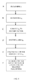
Figure 4 is a flowchart illustrating the method according to the present invention. - The invention will now be described in detail with reference to the attached drawings.
- The present invention relates to a
voltage transformation system 2 comprising a battery system which itself comprises afirst battery 4 and asecond battery 6 connected to one another in series, anequaliser 8 connected to at least one of said first and second batteries and adapted to transforming a first voltage VUT1 to a second voltage VUT2, and abattery sensor 10 which is situated close to saidfirst battery 4 and comprises a first current measuring circuit adapted to determining a value I1 which represents the current through said first battery. - The system further comprises a second
current measuring circuit 12 adapted to determining a value IEQ which represents the equaliser's current to or from the battery system, and to conveying said value to the battery sensor which itself comprises a calculation unit adapted to receiving the values I1 and IEQ and to calculating on the basis of them a value I2 which represents the current through said second battery. The current IEQ at the connection between the battery system and the equaliser may pass in either direction, depending on what state the equaliser is in. - The current through the second battery is easily calculated by the calculation unit by the equation I2 = I1+IEQ.
- In
Figures 1-3 the voltage across the first battery is denoted by V1 and the voltage across the two batteries by V12. - According to a variant of the voltage transformation system, the first voltage may have approximately double the amplitude of the second voltage. For example, the first voltage may be 12 volts and the second voltage 24 volts. In the diagram the output voltage across the two batteries is denoted by VUT1, which substantially corresponds to V12, and the output voltage received via the equaliser is denoted by VUT2, which substantially corresponds to V1.
- According to an embodiment, the first current measuring circuit comprises a current shunt for measuring the current through the first battery, and first and second voltage measuring units for respective measurements of the voltage across said first and second batteries.
- The second current measuring circuit preferably comprises also a current shunt.
- As mentioned above, a current shunt comprises a high-precision resistor with a known resistance and the current through the resistor can easily be determined by Ohm's law by measuring the voltage across the resistor.
- The first and/or second current measuring circuits may instead take the form of a so-called Hall element. The function of the Hall element is based on measuring the magnetic field which forms round a conductor which has current flowing through it. An advantage of this measuring technique is that it uses a current sensor which need not be connected directly to the conductor where the current is to be determined, since no resistance need be inserted, the current being read from outside the conductor.
-
Figures 1-3 depict three different embodiments of the invention which differ in where the second current measuring circuit is located. - In the embodiment in
Figure 1 , thesecond measuring circuit 12 is situated in the equaliser. According to this embodiment, the second current measuring circuit comprises a communication unit adapted to conducting with said battery sensor a transfer of information in one or both directions. The communication is here represented by a double-headed broken-line arrow. The information conveyed from the communication unit to battery sensor takes the form inter alia of values representing measured current IEQ to and from the equaliser. - It may also be appropriate to convey information from the battery sensor to the equaliser, e.g. information about battery status which may be relevant to recharging the batteries in enabling the equaliser to optimise the recharge according to battery status.
- The information exchange between the equaliser and the battery sensor may for example be via LIN (local interconnect network) or CAN (controller area network).
- In the embodiment depicted in
Figure 2 , the second current measuringcircuit 12 is a separate circuit situated on the connection between the equaliser and the battery system. Here again, the current measuring circuit comprises a communication unit for conveying information to the battery sensor, and the information exchange may for example be via LIN or CAN. - In the embodiment depicted in
Figure 3 , the second current measuringcircuit 12 is situated in the battery sensor. In this embodiment the second current measuring circuit is integrated in the battery sensor, which may for example be achieved by having the connection between the battery system and the equaliser pass through the battery sensor. InFigure 3 this is represented by a broken-line arrow from the connection to thebattery sensor 10. - For the battery sensor to be also able to measure rapid processes, e.g. when the starter motor is running, the measurements have to be made at a fast enough rate. The current I1 through the first battery and the current IEQ to and from the equaliser are preferably determined at a measuring frequency of more than 500 Hz. Still more preferably, the measuring rate is over 1000 Hz. The measuring rate may be predetermined and constant. The present invention does of course comprise also measurements at lower measuring rates, e.g. in situations where there is no justification for measuring so often. The measuring rate may also be variable and adaptive, e.g. measurements taking place more often when the starter motor is initiated and significantly less often when the vehicle is parked and the only current being drawn is for example for lighting and radio.
- Determining the battery system's state of charge (SOC) and state of health (SOH) involves a number of parameters for each battery, e.g. the respective voltages across said first and second batteries and the respective currents through said first and second batteries. Other parameters often used are temperature values and times when currents and voltages are measured. These status values for the battery system may be calculated by the calculation unit or by an external unit which has access to necessary parameters, e.g. via LIN or CAN.
- The invention comprises also a method in the voltage transformation system described above. The method is illustrated in general terms by the flowchart in
Figure 4 and comprises - A) determining a value I1 which represents the current through said first battery;
- B) determining a value IEQ which represents the equaliser's current to and from the battery system;
- C) conveying said value IEQ to the battery sensor;
- D) receiving in the calculation unit the values I1 and IEQ, and
- E) calculating on the basis of I1 and IEQ a value I2 which represents the current through said second battery.
- The measurement of I1 and IEQ take place in accordance with the method at a measuring rate which is preferably over 500 Hz and may be predetermined and constant or may vary. Other measuring rates may of course be appropriate as described above in relation to the description of the voltage transformation system.
- The battery sensor is adapted to measuring and/or determining parameters needed for determining one or more status values, e.g. the battery system's state of charge (SOC) and state of health (SOH). These parameters comprise the respective voltages across said first and second batteries and the respective currents through said first and second batteries. Other parameters may be the temperatures of the batteries and the times when the measurements are made.
- According to an embodiment, the method thus also comprises
- F) determining on the basis of said parameters the battery system's state of charge (SOC) and state of health (SOH).
- The present invention is not restricted to the preferred embodiments described above. Sundry alternatives, modifications and equivalents may be used. The above embodiments are therefore not to be regarded as limiting the invention's protective scope which is defined by the attached claims.
Claims (19)
- A voltage transformation system (2) comprising- a battery system comprising a first battery (4) and a second battery (6) connected to one another in series,- an equaliser (8) connected to at least one of said first and second batteries and adapted to transforming a first voltage to a second voltage,- a battery sensor (10) situated close to said first battery (4) and comprising a first current measuring circuit adapted to determining a value I1 which represents the current through said first battery,characterised in that the system further comprises
a second current measuring circuit (12) adapted to determining a value IEQ which represents the equaliser's current to or from the battery system, and to conveying said value to the battery sensor,
and that the battery sensor comprises a calculation unit adapted to receiving the values I1 and IEQ and to calculating on the basis of them a value I2 which represents the current through said second battery. - The voltage transformation system according to claim 1, in which said first current measuring circuit comprises a current shunt for measuring the current through said first battery, and first and second voltage measuring units for respective measurements of the voltage across said first and second batteries.
- The voltage transformation system according to either of claims 1 and 2, in which said second current measuring circuit comprises a current shunt.
- The voltage transformation system according to any one of claims 1-3, in which said equaliser comprises said second current measuring circuit.
- The voltage transformation system according to any one of claims 1-3, in which said battery sensor comprises said second current measuring circuit.
- The voltage transformation system according to any one of claims 1-4, in which said second current measuring circuit comprises a communication unit adapted to conducting with said battery sensor transfer of information in one or both directions.
- The voltage transformation system according to any one of claims 1-6, in which I1 and IEQ are arranged to be determined at a measuring rate of more than 500 Hz.
- The voltage transformation system according to any one of claims 1-7, in which I1 and IEQ are arranged to be determined at an adaptively varying measuring rate.
- The voltage transformation system according to any one of claims 1-8, in which said battery sensor is adapted to measuring and/or determining parameters which are needed for determining one or more status values of the battery system.
- The voltage transformation system according to claim 9, in which said parameters comprise the respective voltages across said first and second batteries and the respective currents through said first and second batteries.
- A method in a voltage transformation system comprising- a battery system comprising a first battery and a second battery connected to one another in series,- an equaliser connected to at least one of said first and second batteries and adapted to transforming a first voltage to a second voltage,- a battery sensor situated close to said first battery and comprising a first current measuring circuit and a calculation unit,characterised in that the method comprisesA) determining a value I1 which represents the current through said first battery;B) determining a value IEQ which represents the equaliser's current to or from the battery system;C) conveying said value IEQ to the battery sensor;D) receiving in the calculation unit the values I1 and IEQ, andE) calculating on the basis of I1 and IEQ a value I2 which represents the current through said second battery.
- The method according to claim 11, in which the voltage transformation system comprises a second current measuring circuit comprising a communication unit adapted to conducting with said battery sensor transfer of information in one or both directions.
- The method according to either of claims 11 and 12, in which second current measuring circuit comprises a current shunt.
- The method according to any one of claims 11-13, in which said first current measuring circuit comprises a current shunt for measuring the current through said first battery, and first and second voltage measuring units for respective measurements of the voltages across said first and second batteries.
- The method according to any one of claims 11-14, in which I1 and IEQ are arranged to be determined at a measuring rate of more than 500 Hz.
- The method according to any one of claims 11-15, in which I1 and IEQ are arranged to be determined at an adaptively varying measuring rate.
- The method according to any one of claims 11-16, in which said battery sensor is adapted to measuring and/or determining parameters which are needed for determining one or more status values of the battery system.
- The method according to claim 17, in which said parameters comprise the respective voltages across said first and second batteries and the respective currents through said first and second batteries.
- The method according to either of claims 17 and 18, comprising F) determining on the basis of said parameters the battery system's state of charge (SOC) and state of health (SOH).
Applications Claiming Priority (1)
| Application Number | Priority Date | Filing Date | Title |
|---|---|---|---|
| SE1150510A SE1150510A1 (en) | 2011-05-31 | 2011-05-31 | Power Conversion Systems |
Publications (1)
| Publication Number | Publication Date |
|---|---|
| EP2538521A1 true EP2538521A1 (en) | 2012-12-26 |
Family
ID=46147315
Family Applications (1)
| Application Number | Title | Priority Date | Filing Date |
|---|---|---|---|
| EP12168252A Withdrawn EP2538521A1 (en) | 2011-05-31 | 2012-05-16 | Voltage transformation system |
Country Status (3)
| Country | Link |
|---|---|
| EP (1) | EP2538521A1 (en) |
| BR (1) | BR102012012447A2 (en) |
| SE (1) | SE1150510A1 (en) |
Cited By (3)
| Publication number | Priority date | Publication date | Assignee | Title |
|---|---|---|---|---|
| WO2016079705A1 (en) * | 2014-11-19 | 2016-05-26 | Iveco S.P.A. | Charging system of a pair of batteries mutually connected in series of a heavy vehicle and heavy vehicle implementing the system |
| CN110764010A (en) * | 2018-07-27 | 2020-02-07 | 康明斯有限公司 | System and method for monitoring a vehicle battery system |
| EP3979449A1 (en) * | 2020-10-05 | 2022-04-06 | Volvo Truck Corporation | A method for reducing the overall power consumption of a parked vehicle |
Citations (5)
| Publication number | Priority date | Publication date | Assignee | Title |
|---|---|---|---|---|
| US6271645B1 (en) * | 2000-02-11 | 2001-08-07 | Delphi Technologies, Inc. | Method for balancing battery pack energy levels |
| US6373223B1 (en) | 2000-11-21 | 2002-04-16 | Nagano Japan Radio Co., Ltd. | Voltage equalizing apparatus and voltage equalizing method for battery devices |
| JP2004194410A (en) * | 2002-12-10 | 2004-07-08 | Denso Corp | Power supply device and control method thereof |
| WO2009145709A1 (en) | 2008-05-28 | 2009-12-03 | Scania Cv Ab (Publ) | Control of battery balance |
| US7808208B2 (en) | 2007-07-20 | 2010-10-05 | Hyundai Mobis Co., Ltd. | Battery equalizer for cars |
-
2011
- 2011-05-31 SE SE1150510A patent/SE1150510A1/en not_active Application Discontinuation
-
2012
- 2012-05-16 EP EP12168252A patent/EP2538521A1/en not_active Withdrawn
- 2012-05-24 BR BR102012012447-5A patent/BR102012012447A2/en not_active IP Right Cessation
Patent Citations (5)
| Publication number | Priority date | Publication date | Assignee | Title |
|---|---|---|---|---|
| US6271645B1 (en) * | 2000-02-11 | 2001-08-07 | Delphi Technologies, Inc. | Method for balancing battery pack energy levels |
| US6373223B1 (en) | 2000-11-21 | 2002-04-16 | Nagano Japan Radio Co., Ltd. | Voltage equalizing apparatus and voltage equalizing method for battery devices |
| JP2004194410A (en) * | 2002-12-10 | 2004-07-08 | Denso Corp | Power supply device and control method thereof |
| US7808208B2 (en) | 2007-07-20 | 2010-10-05 | Hyundai Mobis Co., Ltd. | Battery equalizer for cars |
| WO2009145709A1 (en) | 2008-05-28 | 2009-12-03 | Scania Cv Ab (Publ) | Control of battery balance |
Cited By (5)
| Publication number | Priority date | Publication date | Assignee | Title |
|---|---|---|---|---|
| WO2016079705A1 (en) * | 2014-11-19 | 2016-05-26 | Iveco S.P.A. | Charging system of a pair of batteries mutually connected in series of a heavy vehicle and heavy vehicle implementing the system |
| CN110764010A (en) * | 2018-07-27 | 2020-02-07 | 康明斯有限公司 | System and method for monitoring a vehicle battery system |
| CN110764010B (en) * | 2018-07-27 | 2024-04-02 | 康明斯有限公司 | System and method for monitoring a vehicle battery system |
| EP3979449A1 (en) * | 2020-10-05 | 2022-04-06 | Volvo Truck Corporation | A method for reducing the overall power consumption of a parked vehicle |
| US11584257B2 (en) | 2020-10-05 | 2023-02-21 | Volvo Truck Corporation | Method for reducing the overall power consumption of a parked vehicle |
Also Published As
| Publication number | Publication date |
|---|---|
| BR102012012447A2 (en) | 2013-11-05 |
| SE1150510A1 (en) | 2012-12-01 |
Similar Documents
| Publication | Publication Date | Title |
|---|---|---|
| US10948545B2 (en) | Residual quantity measuring device, battery pack, electric power tool, electric aircraft, electric vehicle, and power supply device | |
| JP7617533B2 (en) | Management device, power supply system, electric vehicle, and management method | |
| CA2941349C (en) | Charging device, charging control method, electricity storage device, power storage device, power system, and electric vehicle | |
| US12539781B2 (en) | Management device and power supply system | |
| JP5641006B2 (en) | Power storage device | |
| US20170144565A1 (en) | Power reserve apparatus, power system, and electric vehicle | |
| CA2923375C (en) | Power storage device and method of controlling power storage device | |
| CN102841318B (en) | Monitoring device and method, monitoring and control equipment and method and power-supply device | |
| EP4239291A1 (en) | Computation system, charging plan creation program, and discharging plan creation program | |
| EP3018791B1 (en) | Power storage device and power storage device control method | |
| CN102848929B (en) | Battery monitor circuit, electrical storage device, electronic installation and electric vehicle | |
| JP7149543B2 (en) | Management device, power storage system | |
| EP2664937A2 (en) | Semiconductor device and voltage measuring device | |
| WO2019181764A1 (en) | Battery control device, battery control method, uninterruptible power supply unit, power system, and electric vehicle | |
| US8233582B2 (en) | High dynamic range coulomb counter which simultaneously monitors multiple sense resistors | |
| SE1150510A1 (en) | Power Conversion Systems | |
| EP3048450B1 (en) | System and method for determining battery usage limits | |
| JP2012054034A (en) | Voltage monitoring circuit and cell power supply device | |
| JP5954381B2 (en) | Power storage system, power consumption device, and electric vehicle | |
| KR20230064134A (en) | Car battery monitoring system |
Legal Events
| Date | Code | Title | Description |
|---|---|---|---|
| PUAI | Public reference made under article 153(3) epc to a published international application that has entered the european phase |
Free format text: ORIGINAL CODE: 0009012 |
|
| AK | Designated contracting states |
Kind code of ref document: A1 Designated state(s): AL AT BE BG CH CY CZ DE DK EE ES FI FR GB GR HR HU IE IS IT LI LT LU LV MC MK MT NL NO PL PT RO RS SE SI SK SM TR |
|
| AX | Request for extension of the european patent |
Extension state: BA ME |
|
| 17P | Request for examination filed |
Effective date: 20130626 |
|
| RBV | Designated contracting states (corrected) |
Designated state(s): AL AT BE BG CH CY CZ DE DK EE ES FI FR GB GR HR HU IE IS IT LI LT LU LV MC MK MT NL NO PL PT RO RS SE SI SK SM TR |
|
| 17Q | First examination report despatched |
Effective date: 20131203 |
|
| STAA | Information on the status of an ep patent application or granted ep patent |
Free format text: STATUS: THE APPLICATION HAS BEEN WITHDRAWN |
|
| 18W | Application withdrawn |
Effective date: 20160427 |