EP2538502A2 - Apparatus for transmission testing of a telecommunications jack - Google Patents
Apparatus for transmission testing of a telecommunications jack Download PDFInfo
- Publication number
- EP2538502A2 EP2538502A2 EP12171971A EP12171971A EP2538502A2 EP 2538502 A2 EP2538502 A2 EP 2538502A2 EP 12171971 A EP12171971 A EP 12171971A EP 12171971 A EP12171971 A EP 12171971A EP 2538502 A2 EP2538502 A2 EP 2538502A2
- Authority
- EP
- European Patent Office
- Prior art keywords
- jack
- base
- holder
- probes
- idcs
- Prior art date
- Legal status (The legal status is an assumption and is not a legal conclusion. Google has not performed a legal analysis and makes no representation as to the accuracy of the status listed.)
- Granted
Links
Images


Classifications
-
- H—ELECTRICITY
- H01—ELECTRIC ELEMENTS
- H01R—ELECTRICALLY-CONDUCTIVE CONNECTIONS; STRUCTURAL ASSOCIATIONS OF A PLURALITY OF MUTUALLY-INSULATED ELECTRICAL CONNECTING ELEMENTS; COUPLING DEVICES; CURRENT COLLECTORS
- H01R24/00—Two-part coupling devices, or either of their cooperating parts, characterised by their overall structure
- H01R24/60—Contacts spaced along planar side wall transverse to longitudinal axis of engagement
- H01R24/62—Sliding engagements with one side only, e.g. modular jack coupling devices
- H01R24/64—Sliding engagements with one side only, e.g. modular jack coupling devices for high frequency, e.g. RJ 45
-
- G—PHYSICS
- G01—MEASURING; TESTING
- G01R—MEASURING ELECTRIC VARIABLES; MEASURING MAGNETIC VARIABLES
- G01R31/00—Arrangements for testing electric properties; Arrangements for locating electric faults; Arrangements for electrical testing characterised by what is being tested not provided for elsewhere
- G01R31/50—Testing of electric apparatus, lines, cables or components for short-circuits, continuity, leakage current or incorrect line connections
- G01R31/66—Testing of connections, e.g. of plugs or non-disconnectable joints
- G01R31/68—Testing of releasable connections, e.g. of terminals mounted on a printed circuit board
- G01R31/69—Testing of releasable connections, e.g. of terminals mounted on a printed circuit board of terminals at the end of a cable or a wire harness; of plugs; of sockets, e.g. wall sockets or power sockets in appliances
-
- H—ELECTRICITY
- H01—ELECTRIC ELEMENTS
- H01R—ELECTRICALLY-CONDUCTIVE CONNECTIONS; STRUCTURAL ASSOCIATIONS OF A PLURALITY OF MUTUALLY-INSULATED ELECTRICAL CONNECTING ELEMENTS; COUPLING DEVICES; CURRENT COLLECTORS
- H01R13/00—Details of coupling devices of the kinds covered by groups H01R12/70 or H01R24/00 - H01R33/00
- H01R13/62—Means for facilitating engagement or disengagement of coupling parts or for holding them in engagement
- H01R13/625—Casing or ring with bayonet engagement
-
- H—ELECTRICITY
- H01—ELECTRIC ELEMENTS
- H01R—ELECTRICALLY-CONDUCTIVE CONNECTIONS; STRUCTURAL ASSOCIATIONS OF A PLURALITY OF MUTUALLY-INSULATED ELECTRICAL CONNECTING ELEMENTS; COUPLING DEVICES; CURRENT COLLECTORS
- H01R13/00—Details of coupling devices of the kinds covered by groups H01R12/70 or H01R24/00 - H01R33/00
- H01R13/02—Contact members
- H01R13/22—Contacts for co-operating by abutting
- H01R13/24—Contacts for co-operating by abutting resilient; resiliently-mounted
- H01R13/2442—Contacts for co-operating by abutting resilient; resiliently-mounted with a single cantilevered beam
-
- H—ELECTRICITY
- H01—ELECTRIC ELEMENTS
- H01R—ELECTRICALLY-CONDUCTIVE CONNECTIONS; STRUCTURAL ASSOCIATIONS OF A PLURALITY OF MUTUALLY-INSULATED ELECTRICAL CONNECTING ELEMENTS; COUPLING DEVICES; CURRENT COLLECTORS
- H01R2201/00—Connectors or connections adapted for particular applications
- H01R2201/20—Connectors or connections adapted for particular applications for testing or measuring purposes
-
- H—ELECTRICITY
- H01—ELECTRIC ELEMENTS
- H01R—ELECTRICALLY-CONDUCTIVE CONNECTIONS; STRUCTURAL ASSOCIATIONS OF A PLURALITY OF MUTUALLY-INSULATED ELECTRICAL CONNECTING ELEMENTS; COUPLING DEVICES; CURRENT COLLECTORS
- H01R4/00—Electrically-conductive connections between two or more conductive members in direct contact, i.e. touching one another; Means for effecting or maintaining such contact; Electrically-conductive connections having two or more spaced connecting locations for conductors and using contact members penetrating insulation
- H01R4/24—Connections using contact members penetrating or cutting insulation or cable strands
- H01R4/2416—Connections using contact members penetrating or cutting insulation or cable strands the contact members having insulation-cutting edges, e.g. of tuning fork type
Definitions
- the present invention relates to an apparatus for transmission testing of a telecommunications jack having a plurality of insulation displacement contacts (IDCs), and to a method of positioning such a telecommunications jack for transmission testing.
- IDCs insulation displacement contacts
- telecommunications networks require testing of their physical components, including connecting hardware such as fixed connectors (jacks). Testing protocols such as those set out in the ANSI/TIA/EIA 568.B and 568.C standards require that twisted-pair cabling used in such networks meet optimum thresholds of certain field-test parameters including insertion loss, near-end crosstalk (NEXT) loss, far-end crosstalk (FEXT), return loss and propagation delay. Connecting hardware used with twisted-pair cabling must meet corresponding Connecting Hardware Transmission Performance standards.
- a test plug connected to field-test equipment is mated to the connecting hardware.
- the connecting hardware requires suitable far end termination in order to complete the test setup.
- 8P8C 8 position 8 contact
- RJ45 jacks this requires terminating physical wires (which are in electrical communication with a printed circuit board) onto the Insulation Displacement Contacts (IDCs) of the jacks. Termination of wires is typically time-consuming and labour-intensive. In addition, the wires have an inherent variability in their length, number of twists, and proximity to each other, all of which can adversely affect the reliability of the testing method.
- an apparatus for transmission testing of a telecommunications jack having a plurality of insulation displacement contacts (IDCs) including:
- the invention thus provides a fixed structure to which jacks can be mounted during testing, and removed after testing is complete.
- the jack is thus retained and kept aligned during the testing procedure, thereby ensuring that a repeatable outcome can be obtained.
- the apparatus of the invention may be used repeatedly, by way of contrast to the wire-termination method in which the wires must be thrown away after testing.
- the same apparatus can be used multiple times, the inherent variability in length, number of twists, and proximity of adjacent wires can be avoided or greatly reduced, thus greatly enhancing the reliability of the testing procedure.
- Providing an apparatus to which jacks can be simply mounted and demounted also saves greatly on time since the time-consuming step of terminating wires onto the IDCs is not required.
- this allows for online testing of jacks during high-speed manufacture - a facility which is not available with known testing methods and apparatus.
- the jack holder is formed separately from the base. This enables the jack to be mounted prior to bringing the IDCs into contact with the probes.
- the base includes one or more guides for aligning the jack holder with the base and the test probes.
- the base includes a cavity to receive a printed circuit board which is in electrical communication with the test probes.
- the apparatus preferably includes a locking mechanism for holding the jack holder fixed relative to the base.
- This may be in the form of a clip which is releasably attachable to the jack holder and to the base.
- the clip may include one or more tongues shaped to engage with corresponding brackets in or on the base.
- the clip includes a plate having a lower surface, and the jack holder includes one or more shoulders, wherein the plate is rotatable to bring the lower surface into engagement with the shoulders of the jack such that the jack remains stationary with respect to the probes.
- the locking mechanism is a simple cam lock which can be released by rotation of the clip, whereby the jack holder is released from the base in order to, in turn, remove the jack.
- the jack holder may include at least one groove shaped to slidingly receive a ridge on an external surface of the jack, thereby to retain the jack.
- each probe has a contact portion which is bent at an angle to a non-contact portion of the probe.
- the angle is preferably 45 degrees or less.
- the present invention provides a method of positioning a telecommunications jack for transmission testing, the jack including a plurality of insulation displacement contacts (IDCs), the method including:
- the jack holder is preferably formed separately from the base, and if so, the probes may be brought into contact with the IDCs after the jack is inserted into the jack holder.
- the method preferably further includes the step of locking the jack holder to the base, whereby the jack is held stationary with respect to the probes.
- the base and/or the jack holder are constructed of non conductive materials. This assists in avoiding spurious errors or interference during the transmission testing procedure.
- IDCs insulation displacement contacts
- the apparatus 10 includes a jack holder 20, which in this example is formed as a separate component.
- the jack holder 20 is configured to removably retain the jack 100 by virtue of opposed grooves 22 which are shaped to receive corresponding one or more ridges 104 formed on external surfaces of the jack 100, as shown in Figures 1 and 4 .
- Apparatus 10 also includes a base 30 for receiving a printed circuit board (PCB) 35 with which a plurality of transmission test probes 31 is in electrical communication.
- PCB 35 is received by and located within an aperture 38 in the base 30 (such that it is restrained against side-to-side movement by the internal walls of base 30) and rests against a seat 36, as best shown in the sectional views of Figures 4 and 5 .
- the PCB 35 and probes 31 are preferably formed as separate components from the base 30 so that they can be replaced as necessary.
- Each member of a pair of probes is insulated from its partner using insulating collar 32.
- each probe 31 will be associated with one of the IDCs, as will later be described.
- the apparatus 10 also features a locking mechanism for holding the jack holder 20 fixed relative to the base 30, such that the jack 100 remains stationary with respect to the probes 31.
- the locking mechanism takes the form of a clip 40 which includes a plate-like portion 42 having a plurality of tongues 43 projecting from its lower surface. The tongues are shaped to engage with corresponding brackets 33 which project from the base 30.
- the jack 100 is inserted into the jack holder 20 by sliding ridge 104 into one of the grooves 22, such that the IDC slots 102 of the jack 100 straddle the central portion 26 ( Figure 2 ), and such that the jack 100 abuts against the stop 24 of jack holder 20.
- the shoulders 28 of jack holder 20 are aligned with guides in the form of recesses 39 of brackets 33 and the jack holder 20 is lowered into the cavity 38, towards PCB 35 which has previously been seated inside the base 30 in abutment with the seat 36.
- the recesses 39 face into the cavity 38 and accommodate the shoulders 28 of jack holder 20 such that it is restrained against side-to-side or rotational movement.
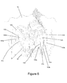
- the probes 31 on PCB 35 are located such that, when the PCB 35 is seated in the base 30 and the shoulders 28 of jack holder 20 are located within brackets 33, the probes 31 align with the positions of IDC towers 101. This ensures that each probe 31 is aligned and associated with one of the IDCs 103, as shown in Figure 6 .
- Each probe 31 has a contact portion in the form of a kinked or angled distal upper portion 31a which points away from the remainder (non-contact portion) of the probe.
- the angle of each upper portion 31a is chosen such that, if the upper portion 31a is not in alignment with the slot 102 as the jack holder 20 is lowered onto the probes 31, the angled upper portions 31a will come into contact with either of the blades 103a, 103b of the insulation displacement contacts 103 housed within IDC towers 101.
- the blades 103a, 103b have angled lower edges which form an angle of approximately 90 degrees therebetween so that as the jack holder 20 is pushed further down towards the probes 31, angled upper portions 31a will tend to slide along whichever of the blades 103a, 103b with which they are in contact such that the upper portion 31a will be trapped between the blades and be located within slot 102 of IDC 103. After the upper portion 31a has been located within the slot 102, further pressure can be applied such that the upper portion 31a can be bent for loading under tension. This is best shown in Figure 6 , in which the external housing of the jack 100 and the jack holder 20 are shown stripped away, so that only the IDCs 103 are visible.
- the angle between the upper portion 31a and the remainder of the probe 31 is preferably around 45 degrees or less in order to provide the required tension.
- Clip 40 has a plate-like portion 42 with a lower surface 45 which is adapted to engage with the top surface of shoulders 28 of the jack holder 20.
- Clip 40 is then rotated until tongues 43 engage with the brackets 33 on the base 30, at which point the lower surface 45 of clip 40 also engages with shoulders 28 of the jack holder 20, so that the base 30 and jack holder 20 are now held fixed relative to each other, thereby preventing any movement of the jack 100 relative to the probes 31.
- the cover 110 of the restrained jack 100 may be flipped to expose the socket of the jack.
- a test plug connected to field testing equipment (not shown) may then be mated with the socket and a suitable battery of tests may be triggered by the field testing equipment.
- tests may be run in accordance with Annexes D and E of ANSI/TIA/EIA/568-C.
Landscapes
- Physics & Mathematics (AREA)
- General Physics & Mathematics (AREA)
- Measuring Leads Or Probes (AREA)
- Testing Electric Properties And Detecting Electric Faults (AREA)
Abstract
Description
- The present invention relates to an apparatus for transmission testing of a telecommunications jack having a plurality of insulation displacement contacts (IDCs), and to a method of positioning such a telecommunications jack for transmission testing.
- To ensure that they meet performance requirements, telecommunications networks require testing of their physical components, including connecting hardware such as fixed connectors (jacks). Testing protocols such as those set out in the ANSI/TIA/EIA 568.B and 568.C standards require that twisted-pair cabling used in such networks meet optimum thresholds of certain field-test parameters including insertion loss, near-end crosstalk (NEXT) loss, far-end crosstalk (FEXT), return loss and propagation delay. Connecting hardware used with twisted-pair cabling must meet corresponding Connecting Hardware Transmission Performance standards.
- In order to perform the above-mentioned tests, a test plug connected to field-test equipment is mated to the connecting hardware. The connecting hardware requires suitable far end termination in order to complete the test setup. In the case of jacks for 8 position 8 contact (8P8C) connectors, generally referred to as "RJ45 jacks", this requires terminating physical wires (which are in electrical communication with a printed circuit board) onto the Insulation Displacement Contacts (IDCs) of the jacks. Termination of wires is typically time-consuming and labour-intensive. In addition, the wires have an inherent variability in their length, number of twists, and proximity to each other, all of which can adversely affect the reliability of the testing method.
- It would be desirable to overcome or alleviate the above mentioned difficulties, or at least provide a useful alternative.
- In accordance with one aspect of the invention, there is provided an apparatus for transmission testing of a telecommunications jack having a plurality of insulation displacement contacts (IDCs), the apparatus including:
- a base;
- a plurality of transmission test probes associated with the base; and
- a jack holder for removably coupling the jack to the base such that IDCs of the jack are in electrical communication with corresponding test probes;
- wherein the jack holder is fixed relative to the base during testing, such that the jack remains stationary with respect to the probes.
- The invention thus provides a fixed structure to which jacks can be mounted during testing, and removed after testing is complete. The jack is thus retained and kept aligned during the testing procedure, thereby ensuring that a repeatable outcome can be obtained.
- The apparatus of the invention may be used repeatedly, by way of contrast to the wire-termination method in which the wires must be thrown away after testing. In addition, since the same apparatus can be used multiple times, the inherent variability in length, number of twists, and proximity of adjacent wires can be avoided or greatly reduced, thus greatly enhancing the reliability of the testing procedure.
- Providing an apparatus to which jacks can be simply mounted and demounted also saves greatly on time since the time-consuming step of terminating wires onto the IDCs is not required. Advantageously, this allows for online testing of jacks during high-speed manufacture - a facility which is not available with known testing methods and apparatus.
- Replacement of wires with direct probes as provided herein may also provide the benefit of shorter far end termination length.
- In a particularly preferred embodiment, the jack holder is formed separately from the base. This enables the jack to be mounted prior to bringing the IDCs into contact with the probes.
- Preferably, the base includes one or more guides for aligning the jack holder with the base and the test probes.
- In one embodiment, the base includes a cavity to receive a printed circuit board which is in electrical communication with the test probes.
- The apparatus preferably includes a locking mechanism for holding the jack holder fixed relative to the base. This may be in the form of a clip which is releasably attachable to the jack holder and to the base. The clip may include one or more tongues shaped to engage with corresponding brackets in or on the base. Preferably, the clip includes a plate having a lower surface, and the jack holder includes one or more shoulders, wherein the plate is rotatable to bring the lower surface into engagement with the shoulders of the jack such that the jack remains stationary with respect to the probes. In this embodiment, the locking mechanism is a simple cam lock which can be released by rotation of the clip, whereby the jack holder is released from the base in order to, in turn, remove the jack.
- The jack holder may include at least one groove shaped to slidingly receive a ridge on an external surface of the jack, thereby to retain the jack.
- Preferably, each probe has a contact portion which is bent at an angle to a non-contact portion of the probe. The angle is preferably 45 degrees or less.
- In a second aspect, the present invention provides a method of positioning a telecommunications jack for transmission testing, the jack including a plurality of insulation displacement contacts (IDCs), the method including:
- providing an apparatus including a base including a plurality of transmission test probes, and a jack holder which is configured to removably retain the jack;
- inserting the jack into the jack holder;
- bringing the probes into contact with the IDCs; and
- holding the jack stationary with respect to the probes.
- The jack holder is preferably formed separately from the base, and if so, the probes may be brought into contact with the IDCs after the jack is inserted into the jack holder.
- The method preferably further includes the step of locking the jack holder to the base, whereby the jack is held stationary with respect to the probes.
- In preferred embodiments, the base and/or the jack holder are constructed of non conductive materials. This assists in avoiding spurious errors or interference during the transmission testing procedure.
- Preferred embodiments of the present invention are hereafter described, by way of nonlimiting example only, with reference to the accompanying drawings in which:
-
Figure 1 is an exploded view of one example of a testing apparatus according to the invention; -
Figure 2 shows the testing apparatus ofFigure 1 in assembled form, with a telecommunications jack mounted to the testing apparatus; -
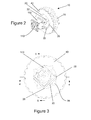
Figure 3 is a top plan view of the testing apparatus and jack shown inFigure 2 ; -
Figure 4 is a section through the line 4-4 ofFigure 3 ; -
Figure 5 is a section through the line 5-5 ofFigure 3 ; and -
Figure 6 is a partial cutaway view of the testing apparatus and jack ofFigure 2 . - Referring to the Figures, there is shown an exemplary apparatus, generally indicated by 10, for transmission testing of a
telecommunications jack 100 having a plurality of insulation displacement contacts (IDCs) which are housed in IDCtowers 101. - The
apparatus 10 includes ajack holder 20, which in this example is formed as a separate component. Thejack holder 20 is configured to removably retain thejack 100 by virtue ofopposed grooves 22 which are shaped to receive corresponding one ormore ridges 104 formed on external surfaces of thejack 100, as shown inFigures 1 and4 . -
Apparatus 10 also includes abase 30 for receiving a printed circuit board (PCB) 35 with which a plurality oftransmission test probes 31 is in electrical communication. When theapparatus 10 is fully assembled (Figures 2 and 3 ), PCB 35 is received by and located within anaperture 38 in the base 30 (such that it is restrained against side-to-side movement by the internal walls of base 30) and rests against aseat 36, as best shown in the sectional views ofFigures 4 and 5 . The PCB 35 andprobes 31 are preferably formed as separate components from thebase 30 so that they can be replaced as necessary. - Each member of a pair of probes is insulated from its partner using
insulating collar 32. When theapparatus 10 is in use, eachprobe 31 will be associated with one of the IDCs, as will later be described. - The
apparatus 10 also features a locking mechanism for holding thejack holder 20 fixed relative to thebase 30, such that thejack 100 remains stationary with respect to theprobes 31. In this embodiment, the locking mechanism takes the form of aclip 40 which includes a plate-like portion 42 having a plurality oftongues 43 projecting from its lower surface. The tongues are shaped to engage withcorresponding brackets 33 which project from thebase 30. - To position the
jack 100 for transmission testing, thejack 100 is inserted into thejack holder 20 by slidingridge 104 into one of thegrooves 22, such that theIDC slots 102 of thejack 100 straddle the central portion 26 (Figure 2 ), and such that thejack 100 abuts against thestop 24 ofjack holder 20. - Once the
jack 100 is positioned in thejack holder 20, theshoulders 28 ofjack holder 20 are aligned with guides in the form ofrecesses 39 ofbrackets 33 and thejack holder 20 is lowered into thecavity 38, towardsPCB 35 which has previously been seated inside the base 30 in abutment with theseat 36. Therecesses 39 face into thecavity 38 and accommodate theshoulders 28 ofjack holder 20 such that it is restrained against side-to-side or rotational movement. - The
probes 31 onPCB 35 are located such that, when thePCB 35 is seated in thebase 30 and theshoulders 28 ofjack holder 20 are located withinbrackets 33, theprobes 31 align with the positions of IDC towers 101. This ensures that eachprobe 31 is aligned and associated with one of theIDCs 103, as shown inFigure 6 . - Each
probe 31 has a contact portion in the form of a kinked or angled distalupper portion 31a which points away from the remainder (non-contact portion) of the probe. The angle of eachupper portion 31a is chosen such that, if theupper portion 31a is not in alignment with theslot 102 as thejack holder 20 is lowered onto theprobes 31, the angledupper portions 31a will come into contact with either of theblades insulation displacement contacts 103 housed within IDC towers 101. Theblades jack holder 20 is pushed further down towards theprobes 31, angledupper portions 31a will tend to slide along whichever of theblades upper portion 31a will be trapped between the blades and be located withinslot 102 ofIDC 103. After theupper portion 31a has been located within theslot 102, further pressure can be applied such that theupper portion 31a can be bent for loading under tension. This is best shown inFigure 6 , in which the external housing of thejack 100 and thejack holder 20 are shown stripped away, so that only theIDCs 103 are visible. The angle between theupper portion 31a and the remainder of theprobe 31 is preferably around 45 degrees or less in order to provide the required tension. - Once the
jack holder 20 has been located inbrackets 33, lowered onto theprobes 31 and seated againstsurfaces 37 of thebrackets 33, it can be locked to the base 30 using theclip 40.Clip 40 has a plate-like portion 42 with alower surface 45 which is adapted to engage with the top surface ofshoulders 28 of thejack holder 20. Thus, once thejack holder 20 is in position, theclip 40 is lowered overjack holder 20 so thatjack holder 20 fits throughaperture 44.Clip 40 is then rotated untiltongues 43 engage with thebrackets 33 on thebase 30, at which point thelower surface 45 ofclip 40 also engages withshoulders 28 of thejack holder 20, so that thebase 30 andjack holder 20 are now held fixed relative to each other, thereby preventing any movement of thejack 100 relative to theprobes 31. - In order to carry out a transmission test, the
cover 110 of the restrainedjack 100 may be flipped to expose the socket of the jack. A test plug connected to field testing equipment (not shown) may then be mated with the socket and a suitable battery of tests may be triggered by the field testing equipment. For example, in the case of a Category 6 (Cat 6) jack, tests may be run in accordance with Annexes D and E of ANSI/TIA/EIA/568-C. - Many modifications will be apparent to those skilled in the art without departing from the scope of the present invention.
- Throughout this specification, unless the context requires otherwise, the word "comprise", and variations such as "comprises" and "comprising", will be understood to imply the inclusion of a stated integer or step or group of integers or steps but not the exclusion of any other integer or step or group of integers or steps.
- The reference to any prior art in this specification is not, and should not be taken as, an acknowledgment or any form of suggestion that the prior art forms part of the common general knowledge in Australia.
Claims (14)
- Apparatus (10) for transmission testing of a telecommunications jack (100) having a plurality of insulation displacement contacts (IDCs) (103), the apparatus (10) including:a base (30);a plurality of transmission test probes (31) associated with the base (30); anda jack holder (20) for removably coupling the jack (100) to the base (30) such that IDCs (103) of the jack (100) are in electrical communication with corresponding test probes (31);wherein the jack holder (20) is fixed relative to the base (30) during testing, such that the jack (100) remains stationary with respect to the probes (31).
- Apparatus according to claim 1, wherein the jack holder (20) is formed separately from the base (30).
- Apparatus according to claim 2, wherein the base (30) includes one or more guides (39) for aligning the jack holder (20) with the base (30) and the test probes (31).
- Apparatus according to any one of claims 1 to 3, wherein the base (30) includes a cavity (38) to receive a printed circuit board (35) which is in electrical communication with the test probes (31).
- Apparatus according to any one of claims 2 to 4, further including a locking mechanism (40) for holding the jack holder (20) fixed relative to the base (30).
- Apparatus according to claim 5, wherein the locking mechanism is a clip (40) which is releasably attachable to the jack holder (20) and to the base (30).
- Apparatus according to claim 6, wherein the clip (40) includes one or more tongues (43) shaped to engage with corresponding brackets (33) in or on the base (30).
- Apparatus according to claim 6 or claim 7, wherein the clip (40) includes a plate (42) having a lower surface (45), and the jack holder (20) includes one or more shoulders (28), wherein the plate (42) is rotatable to bring the lower surface (45) into engagement with the shoulders (28) of the jack holder (20) such that the jack (100) remains stationary with respect to the probes (31).
- Apparatus according to any one of the preceding claims, wherein the jack holder (20) includes at least one groove (22) shaped to slidingly receive a ridge (104) formed on an external surface of the jack (100), thereby to retain the jack (100).
- Apparatus according to any one of the preceding claims, wherein each probe (31) has a contact portion (31a) which is bent at an angle to a non-contact portion of the probe.
- A method of positioning a telecommunications jack (100) for transmission testing, the jack (100) including a plurality of insulation displacement contacts (IDCs) (103), the method including:providing an apparatus (10) including a base (30) associated with a plurality of transmission test probes (31), and a jack holder (20) which is configured to removably retain the jack (100);inserting the jack (100) into the jack holder (20);bringing the probes (31) into contact with the IDCs (103); andholding the jack (100) stationary with respect to the probes (31).
- A method according to claim 11, wherein the jack holder (20) is formed separately from the base (30).
- A method according to claim 12, wherein the probes (31) are brought into contact with the IDCs (103) after the jack (100) is inserted into the jack holder (20).
- A method according to claim 12, further including the step of locking the jack holder (20) to the base (30), whereby the jack (100) is held stationary with respect to the probes (31).
Applications Claiming Priority (1)
| Application Number | Priority Date | Filing Date | Title |
|---|---|---|---|
| AU2011202975A AU2011202975B2 (en) | 2011-06-21 | 2011-06-21 | Apparatus for Transmission Testing of a Telecommunications Jack |
Publications (3)
| Publication Number | Publication Date |
|---|---|
| EP2538502A2 true EP2538502A2 (en) | 2012-12-26 |
| EP2538502A3 EP2538502A3 (en) | 2014-08-06 |
| EP2538502B1 EP2538502B1 (en) | 2016-08-10 |
Family
ID=46245964
Family Applications (1)
| Application Number | Title | Priority Date | Filing Date |
|---|---|---|---|
| EP12171971.0A Not-in-force EP2538502B1 (en) | 2011-06-21 | 2012-06-14 | Apparatus for transmission testing of a telecommunications jack |
Country Status (4)
| Country | Link |
|---|---|
| US (1) | US9337591B2 (en) |
| EP (1) | EP2538502B1 (en) |
| CN (1) | CN102841272B (en) |
| AU (1) | AU2011202975B2 (en) |
Family Cites Families (12)
| Publication number | Priority date | Publication date | Assignee | Title |
|---|---|---|---|---|
| CH508251A (en) * | 1970-07-23 | 1971-05-31 | Cerberus Ag | Ionization fire alarms |
| US4626633A (en) * | 1985-02-04 | 1986-12-02 | Illinois Tool Works, Inc. | In-line switched telephone line tester |
| US4734651A (en) * | 1986-06-30 | 1988-03-29 | Amp Incorporated | Electrical continuity and short circuit testing |
| US4959609A (en) * | 1988-01-27 | 1990-09-25 | Manfred Prokopp | Electrical connecting apparatus for an electrical or electronic testing unit |
| US5247259A (en) * | 1991-07-26 | 1993-09-21 | Amp Incorporated | Cable testing method and apparatus |
| US6019612A (en) * | 1997-02-10 | 2000-02-01 | Kabushiki Kaisha Nihon Micronics | Electrical connecting apparatus for electrically connecting a device to be tested |
| US6089894A (en) * | 1998-05-29 | 2000-07-18 | 3Com Technologies | Test connector |
| US6293815B1 (en) * | 1998-12-21 | 2001-09-25 | Lucent Technologies, Inc. | Connector having self-sealing membrane |
| US6731118B2 (en) * | 2001-06-07 | 2004-05-04 | Sumitomo Wiring System Ltd. | Connector inspection apparatus |
| US20070036489A1 (en) * | 2005-08-15 | 2007-02-15 | Barbara Grzegorzewska | Industrial interconnect system incorporating transceiver module cage |
| US7381098B2 (en) * | 2006-04-11 | 2008-06-03 | Adc Telecommunications, Inc. | Telecommunications jack with crosstalk multi-zone crosstalk compensation and method for designing |
| DK2220729T3 (en) * | 2007-11-13 | 2017-11-20 | Linak As | An actuator system |
-
2011
- 2011-06-21 AU AU2011202975A patent/AU2011202975B2/en not_active Ceased
-
2012
- 2012-06-14 EP EP12171971.0A patent/EP2538502B1/en not_active Not-in-force
- 2012-06-15 US US13/524,448 patent/US9337591B2/en not_active Expired - Fee Related
- 2012-06-21 CN CN201210212159.0A patent/CN102841272B/en not_active Expired - Fee Related
Non-Patent Citations (1)
| Title |
|---|
| None |
Also Published As
| Publication number | Publication date |
|---|---|
| AU2011202975B2 (en) | 2016-11-24 |
| CN102841272B (en) | 2016-08-24 |
| EP2538502B1 (en) | 2016-08-10 |
| US9337591B2 (en) | 2016-05-10 |
| AU2011202975A1 (en) | 2013-01-17 |
| CN102841272A (en) | 2012-12-26 |
| US20120326741A1 (en) | 2012-12-27 |
| EP2538502A3 (en) | 2014-08-06 |
Similar Documents
| Publication | Publication Date | Title |
|---|---|---|
| US5460545A (en) | Patch connector | |
| US7635285B2 (en) | Network connector and connection system | |
| US7229309B2 (en) | Network connection system | |
| US9172188B2 (en) | Plug for a data and/or telecommunication cable comprising several conductors | |
| US4759723A (en) | Patch connector | |
| US9627827B2 (en) | Communication outlet with shutter mechanism and wire manager | |
| KR101562778B1 (en) | - - plug-in connector and method for connecting electrical conductors to a plug-in connector | |
| US20160036179A1 (en) | Communication outlet with shutter mechanism and wire manager | |
| JP2008513954A (en) | Connector assembly containing an insulating displacement element | |
| EP2532052A1 (en) | Electrical connector assembly and method | |
| US4925393A (en) | 66 Block adapter | |
| US9306296B2 (en) | Contacting device of an electric plug-in connector | |
| US11870190B2 (en) | Anti-arc connector and pin array for a port | |
| US6193542B1 (en) | Modular electrical plug and plug-cable assembly including the same | |
| WO2008140693A1 (en) | Sequencing connection device | |
| EP2939314A1 (en) | Interface adapter | |
| US20060160407A1 (en) | Network connection system | |
| US6409535B1 (en) | Modular electrical plug and plug-cable assembly including the same | |
| US11482352B2 (en) | Quick connecting twisted pair cables | |
| AU2011202975B2 (en) | Apparatus for Transmission Testing of a Telecommunications Jack | |
| US4909753A (en) | Patch connector | |
| AU760804B2 (en) | Modular electrical plug and plug-cable assembly including the same | |
| US8357011B2 (en) | Plug assembly for telecommunications cable | |
| US7097493B1 (en) | Apparatus and method for interfacing connectors to network components | |
| EP2424049A2 (en) | Electronic device with modular jack |
Legal Events
| Date | Code | Title | Description |
|---|---|---|---|
| PUAI | Public reference made under article 153(3) epc to a published international application that has entered the european phase |
Free format text: ORIGINAL CODE: 0009012 |
|
| AK | Designated contracting states |
Kind code of ref document: A2 Designated state(s): AL AT BE BG CH CY CZ DE DK EE ES FI FR GB GR HR HU IE IS IT LI LT LU LV MC MK MT NL NO PL PT RO RS SE SI SK SM TR |
|
| AX | Request for extension of the european patent |
Extension state: BA ME |
|
| PUAL | Search report despatched |
Free format text: ORIGINAL CODE: 0009013 |
|
| AK | Designated contracting states |
Kind code of ref document: A3 Designated state(s): AL AT BE BG CH CY CZ DE DK EE ES FI FR GB GR HR HU IE IS IT LI LT LU LV MC MK MT NL NO PL PT RO RS SE SI SK SM TR |
|
| AX | Request for extension of the european patent |
Extension state: BA ME |
|
| RIC1 | Information provided on ipc code assigned before grant |
Ipc: H01R 4/24 20060101ALN20140630BHEP Ipc: G01R 1/04 20060101ALI20140630BHEP Ipc: H01R 24/64 20110101AFI20140630BHEP Ipc: H01R 13/24 20060101ALN20140630BHEP Ipc: H01R 13/625 20060101ALI20140630BHEP Ipc: G01R 31/04 20060101ALI20140630BHEP |
|
| 17P | Request for examination filed |
Effective date: 20140723 |
|
| RBV | Designated contracting states (corrected) |
Designated state(s): AL AT BE BG CH CY CZ DE DK EE ES FI FR GB GR HR HU IE IS IT LI LT LU LV MC MK MT NL NO PL PT RO RS SE SI SK SM TR |
|
| RIC1 | Information provided on ipc code assigned before grant |
Ipc: G01R 31/04 20060101ALI20151207BHEP Ipc: H01R 13/24 20060101ALN20151207BHEP Ipc: H01R 4/24 20060101ALN20151207BHEP Ipc: G01R 1/04 20060101ALI20151207BHEP Ipc: H01R 13/625 20060101ALI20151207BHEP Ipc: H01R 24/64 20110101AFI20151207BHEP |
|
| GRAP | Despatch of communication of intention to grant a patent |
Free format text: ORIGINAL CODE: EPIDOSNIGR1 |
|
| INTG | Intention to grant announced |
Effective date: 20160115 |
|
| GRAS | Grant fee paid |
Free format text: ORIGINAL CODE: EPIDOSNIGR3 |
|
| GRAA | (expected) grant |
Free format text: ORIGINAL CODE: 0009210 |
|
| AK | Designated contracting states |
Kind code of ref document: B1 Designated state(s): AL AT BE BG CH CY CZ DE DK EE ES FI FR GB GR HR HU IE IS IT LI LT LU LV MC MK MT NL NO PL PT RO RS SE SI SK SM TR |
|
| REG | Reference to a national code |
Ref country code: GB Ref legal event code: FG4D |
|
| REG | Reference to a national code |
Ref country code: CH Ref legal event code: EP Ref country code: AT Ref legal event code: REF Ref document number: 819790 Country of ref document: AT Kind code of ref document: T Effective date: 20160815 |
|
| REG | Reference to a national code |
Ref country code: IE Ref legal event code: FG4D |
|
| REG | Reference to a national code |
Ref country code: DE Ref legal event code: R096 Ref document number: 602012021386 Country of ref document: DE |
|
| REG | Reference to a national code |
Ref country code: LT Ref legal event code: MG4D |
|
| REG | Reference to a national code |
Ref country code: NL Ref legal event code: MP Effective date: 20160810 |
|
| REG | Reference to a national code |
Ref country code: AT Ref legal event code: MK05 Ref document number: 819790 Country of ref document: AT Kind code of ref document: T Effective date: 20160810 |
|
| PG25 | Lapsed in a contracting state [announced via postgrant information from national office to epo] |
Ref country code: LT Free format text: LAPSE BECAUSE OF FAILURE TO SUBMIT A TRANSLATION OF THE DESCRIPTION OR TO PAY THE FEE WITHIN THE PRESCRIBED TIME-LIMIT Effective date: 20160810 Ref country code: NL Free format text: LAPSE BECAUSE OF FAILURE TO SUBMIT A TRANSLATION OF THE DESCRIPTION OR TO PAY THE FEE WITHIN THE PRESCRIBED TIME-LIMIT Effective date: 20160810 Ref country code: RS Free format text: LAPSE BECAUSE OF FAILURE TO SUBMIT A TRANSLATION OF THE DESCRIPTION OR TO PAY THE FEE WITHIN THE PRESCRIBED TIME-LIMIT Effective date: 20160810 Ref country code: FI Free format text: LAPSE BECAUSE OF FAILURE TO SUBMIT A TRANSLATION OF THE DESCRIPTION OR TO PAY THE FEE WITHIN THE PRESCRIBED TIME-LIMIT Effective date: 20160810 Ref country code: IT Free format text: LAPSE BECAUSE OF FAILURE TO SUBMIT A TRANSLATION OF THE DESCRIPTION OR TO PAY THE FEE WITHIN THE PRESCRIBED TIME-LIMIT Effective date: 20160810 Ref country code: IS Free format text: LAPSE BECAUSE OF FAILURE TO SUBMIT A TRANSLATION OF THE DESCRIPTION OR TO PAY THE FEE WITHIN THE PRESCRIBED TIME-LIMIT Effective date: 20161210 Ref country code: HR Free format text: LAPSE BECAUSE OF FAILURE TO SUBMIT A TRANSLATION OF THE DESCRIPTION OR TO PAY THE FEE WITHIN THE PRESCRIBED TIME-LIMIT Effective date: 20160810 Ref country code: NO Free format text: LAPSE BECAUSE OF FAILURE TO SUBMIT A TRANSLATION OF THE DESCRIPTION OR TO PAY THE FEE WITHIN THE PRESCRIBED TIME-LIMIT Effective date: 20161110 |
|
| PG25 | Lapsed in a contracting state [announced via postgrant information from national office to epo] |
Ref country code: GR Free format text: LAPSE BECAUSE OF FAILURE TO SUBMIT A TRANSLATION OF THE DESCRIPTION OR TO PAY THE FEE WITHIN THE PRESCRIBED TIME-LIMIT Effective date: 20161111 Ref country code: ES Free format text: LAPSE BECAUSE OF FAILURE TO SUBMIT A TRANSLATION OF THE DESCRIPTION OR TO PAY THE FEE WITHIN THE PRESCRIBED TIME-LIMIT Effective date: 20160810 Ref country code: PL Free format text: LAPSE BECAUSE OF FAILURE TO SUBMIT A TRANSLATION OF THE DESCRIPTION OR TO PAY THE FEE WITHIN THE PRESCRIBED TIME-LIMIT Effective date: 20160810 Ref country code: AT Free format text: LAPSE BECAUSE OF FAILURE TO SUBMIT A TRANSLATION OF THE DESCRIPTION OR TO PAY THE FEE WITHIN THE PRESCRIBED TIME-LIMIT Effective date: 20160810 Ref country code: PT Free format text: LAPSE BECAUSE OF FAILURE TO SUBMIT A TRANSLATION OF THE DESCRIPTION OR TO PAY THE FEE WITHIN THE PRESCRIBED TIME-LIMIT Effective date: 20161212 Ref country code: SE Free format text: LAPSE BECAUSE OF FAILURE TO SUBMIT A TRANSLATION OF THE DESCRIPTION OR TO PAY THE FEE WITHIN THE PRESCRIBED TIME-LIMIT Effective date: 20160810 Ref country code: LV Free format text: LAPSE BECAUSE OF FAILURE TO SUBMIT A TRANSLATION OF THE DESCRIPTION OR TO PAY THE FEE WITHIN THE PRESCRIBED TIME-LIMIT Effective date: 20160810 |
|
| RAP2 | Party data changed (patent owner data changed or rights of a patent transferred) |
Owner name: COMMSCOPE EMEA LIMITED |
|
| RAP2 | Party data changed (patent owner data changed or rights of a patent transferred) |
Owner name: COMMSCOPE TECHNOLOGIES LLC |
|
| PG25 | Lapsed in a contracting state [announced via postgrant information from national office to epo] |
Ref country code: EE Free format text: LAPSE BECAUSE OF FAILURE TO SUBMIT A TRANSLATION OF THE DESCRIPTION OR TO PAY THE FEE WITHIN THE PRESCRIBED TIME-LIMIT Effective date: 20160810 Ref country code: RO Free format text: LAPSE BECAUSE OF FAILURE TO SUBMIT A TRANSLATION OF THE DESCRIPTION OR TO PAY THE FEE WITHIN THE PRESCRIBED TIME-LIMIT Effective date: 20160810 |
|
| REG | Reference to a national code |
Ref country code: DE Ref legal event code: R097 Ref document number: 602012021386 Country of ref document: DE |
|
| PG25 | Lapsed in a contracting state [announced via postgrant information from national office to epo] |
Ref country code: BG Free format text: LAPSE BECAUSE OF FAILURE TO SUBMIT A TRANSLATION OF THE DESCRIPTION OR TO PAY THE FEE WITHIN THE PRESCRIBED TIME-LIMIT Effective date: 20161110 Ref country code: SM Free format text: LAPSE BECAUSE OF FAILURE TO SUBMIT A TRANSLATION OF THE DESCRIPTION OR TO PAY THE FEE WITHIN THE PRESCRIBED TIME-LIMIT Effective date: 20160810 Ref country code: SK Free format text: LAPSE BECAUSE OF FAILURE TO SUBMIT A TRANSLATION OF THE DESCRIPTION OR TO PAY THE FEE WITHIN THE PRESCRIBED TIME-LIMIT Effective date: 20160810 Ref country code: DK Free format text: LAPSE BECAUSE OF FAILURE TO SUBMIT A TRANSLATION OF THE DESCRIPTION OR TO PAY THE FEE WITHIN THE PRESCRIBED TIME-LIMIT Effective date: 20160810 Ref country code: CZ Free format text: LAPSE BECAUSE OF FAILURE TO SUBMIT A TRANSLATION OF THE DESCRIPTION OR TO PAY THE FEE WITHIN THE PRESCRIBED TIME-LIMIT Effective date: 20160810 Ref country code: BE Free format text: LAPSE BECAUSE OF FAILURE TO SUBMIT A TRANSLATION OF THE DESCRIPTION OR TO PAY THE FEE WITHIN THE PRESCRIBED TIME-LIMIT Effective date: 20160810 |
|
| PLBE | No opposition filed within time limit |
Free format text: ORIGINAL CODE: 0009261 |
|
| STAA | Information on the status of an ep patent application or granted ep patent |
Free format text: STATUS: NO OPPOSITION FILED WITHIN TIME LIMIT |
|
| 26N | No opposition filed |
Effective date: 20170511 |
|
| PG25 | Lapsed in a contracting state [announced via postgrant information from national office to epo] |
Ref country code: SI Free format text: LAPSE BECAUSE OF FAILURE TO SUBMIT A TRANSLATION OF THE DESCRIPTION OR TO PAY THE FEE WITHIN THE PRESCRIBED TIME-LIMIT Effective date: 20160810 |
|
| REG | Reference to a national code |
Ref country code: DE Ref legal event code: R119 Ref document number: 602012021386 Country of ref document: DE |
|
| PG25 | Lapsed in a contracting state [announced via postgrant information from national office to epo] |
Ref country code: MC Free format text: LAPSE BECAUSE OF FAILURE TO SUBMIT A TRANSLATION OF THE DESCRIPTION OR TO PAY THE FEE WITHIN THE PRESCRIBED TIME-LIMIT Effective date: 20160810 |
|
| REG | Reference to a national code |
Ref country code: CH Ref legal event code: PL |
|
| GBPC | Gb: european patent ceased through non-payment of renewal fee |
Effective date: 20170614 |
|
| REG | Reference to a national code |
Ref country code: IE Ref legal event code: MM4A |
|
| REG | Reference to a national code |
Ref country code: FR Ref legal event code: ST Effective date: 20180228 |
|
| PG25 | Lapsed in a contracting state [announced via postgrant information from national office to epo] |
Ref country code: LI Free format text: LAPSE BECAUSE OF NON-PAYMENT OF DUE FEES Effective date: 20170630 Ref country code: CH Free format text: LAPSE BECAUSE OF NON-PAYMENT OF DUE FEES Effective date: 20170630 Ref country code: LU Free format text: LAPSE BECAUSE OF NON-PAYMENT OF DUE FEES Effective date: 20170614 Ref country code: GB Free format text: LAPSE BECAUSE OF NON-PAYMENT OF DUE FEES Effective date: 20170614 Ref country code: IE Free format text: LAPSE BECAUSE OF NON-PAYMENT OF DUE FEES Effective date: 20170614 Ref country code: DE Free format text: LAPSE BECAUSE OF NON-PAYMENT OF DUE FEES Effective date: 20180103 |
|
| PG25 | Lapsed in a contracting state [announced via postgrant information from national office to epo] |
Ref country code: FR Free format text: LAPSE BECAUSE OF NON-PAYMENT OF DUE FEES Effective date: 20170630 |
|
| PG25 | Lapsed in a contracting state [announced via postgrant information from national office to epo] |
Ref country code: MT Free format text: LAPSE BECAUSE OF NON-PAYMENT OF DUE FEES Effective date: 20170614 |
|
| PG25 | Lapsed in a contracting state [announced via postgrant information from national office to epo] |
Ref country code: AL Free format text: LAPSE BECAUSE OF FAILURE TO SUBMIT A TRANSLATION OF THE DESCRIPTION OR TO PAY THE FEE WITHIN THE PRESCRIBED TIME-LIMIT Effective date: 20160810 |
|
| PG25 | Lapsed in a contracting state [announced via postgrant information from national office to epo] |
Ref country code: HU Free format text: LAPSE BECAUSE OF FAILURE TO SUBMIT A TRANSLATION OF THE DESCRIPTION OR TO PAY THE FEE WITHIN THE PRESCRIBED TIME-LIMIT; INVALID AB INITIO Effective date: 20120614 |
|
| PG25 | Lapsed in a contracting state [announced via postgrant information from national office to epo] |
Ref country code: CY Free format text: LAPSE BECAUSE OF NON-PAYMENT OF DUE FEES Effective date: 20160810 |
|
| PG25 | Lapsed in a contracting state [announced via postgrant information from national office to epo] |
Ref country code: MK Free format text: LAPSE BECAUSE OF FAILURE TO SUBMIT A TRANSLATION OF THE DESCRIPTION OR TO PAY THE FEE WITHIN THE PRESCRIBED TIME-LIMIT Effective date: 20160810 |
|
| PG25 | Lapsed in a contracting state [announced via postgrant information from national office to epo] |
Ref country code: TR Free format text: LAPSE BECAUSE OF FAILURE TO SUBMIT A TRANSLATION OF THE DESCRIPTION OR TO PAY THE FEE WITHIN THE PRESCRIBED TIME-LIMIT Effective date: 20160810 |