EP2538483A1 - Secondary cell and secondary cell production device - Google Patents
Secondary cell and secondary cell production device Download PDFInfo
- Publication number
- EP2538483A1 EP2538483A1 EP11742359A EP11742359A EP2538483A1 EP 2538483 A1 EP2538483 A1 EP 2538483A1 EP 11742359 A EP11742359 A EP 11742359A EP 11742359 A EP11742359 A EP 11742359A EP 2538483 A1 EP2538483 A1 EP 2538483A1
- Authority
- EP
- European Patent Office
- Prior art keywords
- electrode plate
- negative electrode
- positive electrode
- plate
- cover
- Prior art date
- Legal status (The legal status is an assumption and is not a legal conclusion. Google has not performed a legal analysis and makes no representation as to the accuracy of the status listed.)
- Withdrawn
Links
- 238000004519 manufacturing process Methods 0.000 title claims description 36
- 230000005484 gravity Effects 0.000 abstract description 8
- 230000007246 mechanism Effects 0.000 description 11
- 238000003780 insertion Methods 0.000 description 10
- 230000037431 insertion Effects 0.000 description 10
- 238000003825 pressing Methods 0.000 description 5
- 239000011810 insulating material Substances 0.000 description 3
- 230000006698 induction Effects 0.000 description 2
- 238000000034 method Methods 0.000 description 2
- 238000004080 punching Methods 0.000 description 2
- 238000005452 bending Methods 0.000 description 1
- 230000006835 compression Effects 0.000 description 1
- 238000007906 compression Methods 0.000 description 1
- 230000008021 deposition Effects 0.000 description 1
- 230000000694 effects Effects 0.000 description 1
- 238000002360 preparation method Methods 0.000 description 1
- 239000003923 scrap metal Substances 0.000 description 1
- 239000000126 substance Substances 0.000 description 1
Images






Classifications
-
- H—ELECTRICITY
- H01—ELECTRIC ELEMENTS
- H01M—PROCESSES OR MEANS, e.g. BATTERIES, FOR THE DIRECT CONVERSION OF CHEMICAL ENERGY INTO ELECTRICAL ENERGY
- H01M50/00—Constructional details or processes of manufacture of the non-active parts of electrochemical cells other than fuel cells, e.g. hybrid cells
- H01M50/50—Current conducting connections for cells or batteries
- H01M50/531—Electrode connections inside a battery casing
- H01M50/54—Connection of several leads or tabs of plate-like electrode stacks, e.g. electrode pole straps or bridges
-
- H—ELECTRICITY
- H01—ELECTRIC ELEMENTS
- H01M—PROCESSES OR MEANS, e.g. BATTERIES, FOR THE DIRECT CONVERSION OF CHEMICAL ENERGY INTO ELECTRICAL ENERGY
- H01M10/00—Secondary cells; Manufacture thereof
- H01M10/04—Construction or manufacture in general
- H01M10/0404—Machines for assembling batteries
-
- H—ELECTRICITY
- H01—ELECTRIC ELEMENTS
- H01M—PROCESSES OR MEANS, e.g. BATTERIES, FOR THE DIRECT CONVERSION OF CHEMICAL ENERGY INTO ELECTRICAL ENERGY
- H01M10/00—Secondary cells; Manufacture thereof
- H01M10/04—Construction or manufacture in general
- H01M10/0413—Large-sized flat cells or batteries for motive or stationary systems with plate-like electrodes
-
- H—ELECTRICITY
- H01—ELECTRIC ELEMENTS
- H01M—PROCESSES OR MEANS, e.g. BATTERIES, FOR THE DIRECT CONVERSION OF CHEMICAL ENERGY INTO ELECTRICAL ENERGY
- H01M10/00—Secondary cells; Manufacture thereof
- H01M10/04—Construction or manufacture in general
- H01M10/0468—Compression means for stacks of electrodes and separators
-
- H—ELECTRICITY
- H01—ELECTRIC ELEMENTS
- H01M—PROCESSES OR MEANS, e.g. BATTERIES, FOR THE DIRECT CONVERSION OF CHEMICAL ENERGY INTO ELECTRICAL ENERGY
- H01M10/00—Secondary cells; Manufacture thereof
- H01M10/04—Construction or manufacture in general
- H01M10/049—Processes for forming or storing electrodes in the battery container
-
- H—ELECTRICITY
- H01—ELECTRIC ELEMENTS
- H01M—PROCESSES OR MEANS, e.g. BATTERIES, FOR THE DIRECT CONVERSION OF CHEMICAL ENERGY INTO ELECTRICAL ENERGY
- H01M10/00—Secondary cells; Manufacture thereof
- H01M10/05—Accumulators with non-aqueous electrolyte
- H01M10/052—Li-accumulators
-
- H—ELECTRICITY
- H01—ELECTRIC ELEMENTS
- H01M—PROCESSES OR MEANS, e.g. BATTERIES, FOR THE DIRECT CONVERSION OF CHEMICAL ENERGY INTO ELECTRICAL ENERGY
- H01M50/00—Constructional details or processes of manufacture of the non-active parts of electrochemical cells other than fuel cells, e.g. hybrid cells
- H01M50/10—Primary casings; Jackets or wrappings
- H01M50/102—Primary casings; Jackets or wrappings characterised by their shape or physical structure
- H01M50/103—Primary casings; Jackets or wrappings characterised by their shape or physical structure prismatic or rectangular
-
- H—ELECTRICITY
- H01—ELECTRIC ELEMENTS
- H01M—PROCESSES OR MEANS, e.g. BATTERIES, FOR THE DIRECT CONVERSION OF CHEMICAL ENERGY INTO ELECTRICAL ENERGY
- H01M50/00—Constructional details or processes of manufacture of the non-active parts of electrochemical cells other than fuel cells, e.g. hybrid cells
- H01M50/10—Primary casings; Jackets or wrappings
- H01M50/147—Lids or covers
- H01M50/166—Lids or covers characterised by the methods of assembling casings with lids
-
- H—ELECTRICITY
- H01—ELECTRIC ELEMENTS
- H01M—PROCESSES OR MEANS, e.g. BATTERIES, FOR THE DIRECT CONVERSION OF CHEMICAL ENERGY INTO ELECTRICAL ENERGY
- H01M50/00—Constructional details or processes of manufacture of the non-active parts of electrochemical cells other than fuel cells, e.g. hybrid cells
- H01M50/50—Current conducting connections for cells or batteries
- H01M50/528—Fixed electrical connections, i.e. not intended for disconnection
-
- Y—GENERAL TAGGING OF NEW TECHNOLOGICAL DEVELOPMENTS; GENERAL TAGGING OF CROSS-SECTIONAL TECHNOLOGIES SPANNING OVER SEVERAL SECTIONS OF THE IPC; TECHNICAL SUBJECTS COVERED BY FORMER USPC CROSS-REFERENCE ART COLLECTIONS [XRACs] AND DIGESTS
- Y02—TECHNOLOGIES OR APPLICATIONS FOR MITIGATION OR ADAPTATION AGAINST CLIMATE CHANGE
- Y02E—REDUCTION OF GREENHOUSE GAS [GHG] EMISSIONS, RELATED TO ENERGY GENERATION, TRANSMISSION OR DISTRIBUTION
- Y02E60/00—Enabling technologies; Technologies with a potential or indirect contribution to GHG emissions mitigation
- Y02E60/10—Energy storage using batteries
-
- Y—GENERAL TAGGING OF NEW TECHNOLOGICAL DEVELOPMENTS; GENERAL TAGGING OF CROSS-SECTIONAL TECHNOLOGIES SPANNING OVER SEVERAL SECTIONS OF THE IPC; TECHNICAL SUBJECTS COVERED BY FORMER USPC CROSS-REFERENCE ART COLLECTIONS [XRACs] AND DIGESTS
- Y02—TECHNOLOGIES OR APPLICATIONS FOR MITIGATION OR ADAPTATION AGAINST CLIMATE CHANGE
- Y02P—CLIMATE CHANGE MITIGATION TECHNOLOGIES IN THE PRODUCTION OR PROCESSING OF GOODS
- Y02P70/00—Climate change mitigation technologies in the production process for final industrial or consumer products
- Y02P70/50—Manufacturing or production processes characterised by the final manufactured product
-
- Y—GENERAL TAGGING OF NEW TECHNOLOGICAL DEVELOPMENTS; GENERAL TAGGING OF CROSS-SECTIONAL TECHNOLOGIES SPANNING OVER SEVERAL SECTIONS OF THE IPC; TECHNICAL SUBJECTS COVERED BY FORMER USPC CROSS-REFERENCE ART COLLECTIONS [XRACs] AND DIGESTS
- Y10—TECHNICAL SUBJECTS COVERED BY FORMER USPC
- Y10T—TECHNICAL SUBJECTS COVERED BY FORMER US CLASSIFICATION
- Y10T29/00—Metal working
- Y10T29/53—Means to assemble or disassemble
- Y10T29/5313—Means to assemble electrical device
- Y10T29/53135—Storage cell or battery
Definitions
- the present invention relates to a secondary battery in which a positive electrode plate and a negative electrode plate are stacked, and a secondary battery manufacturing apparatus for manufacturing the secondary battery.
- a stack-type secondary battery has an electrode body in which a positive electrode plate and a negative electrode plate with tabs formed at edges thereof are alternately stacked, and a positive electrode terminal and a negative electrode terminal correspondingly connected to the tabs of the positive electrode plate and the negative electrode plate, respectively.
- a separator formed of an insulating material is arranged between the plates (e.g., see Patent Document 1).
- the separator may have a pouch shape to surround the negative electrode plate to be insulated from the positive electrode plate (e.g., see Patent Document 2).
- the positive electrode plate and the negative electrode plate should be precisely stacked, and in general, the positive electrode plate and the negative electrode plate are alternately stacked with being positioned by a positioning pin, etc.
- Patent Document 1 Japanese Patent Application Laid-Open No. 2006-339054
- Patent Document 2 Japanese Patent Application Laid-Open No. 2003-45498
- the size of the positive electrode plate and the size of the negative electrode plate as described in Patent Documents 1 and 2 are different from each other in general.
- the total size for one electrode plate becomes larger because the separator is rimmed to form the pouch.
- the other electrode plate having a smaller size cannot be positioned by the pin due to interference with the previously stacked electrode plate. Therefore, to position the electrode plate accurately, it is needed to use a conveyor having high accuracy to position the electrode plate. As a result, an electrode body cannot be formed, that the electrode plates are arranged with high accuracy. Even when the electrode body can be formed, it is needed to have long time to position the electrode plates. Therefore, the cost of its production may be increased.
- the present invention has been made in view of the above-described circumstances, and an object of the invention is to provide a secondary battery without the positional error substantially when the size of the positive electrode plate and the size of the negative electrode plate are different from each other, which is achieved by precise positioning and stacking both of the electrode plates, and an apparatus for manufacturing the same secondary battery.
- a secondary battery manufacturing apparatus of the present invention includes: a cover fixing part to fix a cover having shaft parts of a positive electrode terminal and a negative electrode terminal in order that the shaft parts are directed upward; a positive electrode plate conveyance part to convey a positive electrode plate having a tab in which a first through-hole is formed and which is arranged to be line-symmetrical with respect to a centerline of the positive electrode plate, to the cover fixing part; a positive electrode plate disposing part to insert the first through-hole of the conveyed positive electrode plate into the shaft part of the positive electrode terminal; a negative electrode plate conveyance part to convey a negative electrode plate having a tab in which a second through-hole is formed and which is arranged to be line-symmetrical with respect to a centerline of the negative electrode plate, to the cover fixing part; a negative electrode plate disposing part to insert the second through-hole of the conveyed negative electrode plate into the shaft part of the negative electrode terminal and to stack the negative electrode plate on the positive electrode plate; and a cover fixing part to fix a cover
- the positive electrode plate and the negative electrode plate are hung.
- the tab is arranged to be line-symmetrical with respect to a centerline (to be defined later)
- the positive electrode plate and the negative electrode plate supported and hung by the tab coincide with directions of the centerlines thereof to be automatically positioned. Therefore, it is possible to manufacture the secondary battery in which both of the electrode plates are precisely positioned and stacked.
- a secondary battery of the present invention includes: an electrode body in which a positive electrode plate and a negative electrode plate are alternately stacked through a separator; a case to store the electrode body; and a cover having a positive electrode terminal and a negative electrode terminal and fitted to the case, wherein the positive electrode plate includes a positive electrode main body having a substantial plate shape, and a first tab arranged to be line-symmetrical with respect to a centerline of the positive electrode plate and connected to the positive electrode main body and the positive electrode terminal, the negative electrode plate includes a negative electrode main body having a substantial plate shape, and a second tab arranged to be line-symmetrical with respect to a centerline of the negative electrode plate and connected to the negative electrode main body and the negative electrode terminal, and the first tab and the second tab are arranged not to overlap each other when the tabs are stacked.
- the tabs thereof are arranged to be line-symmetrical with respect to centerlines thereof. Accordingly, the electrode plates are precisely positioned and stacked.
- the secondary battery is assembled to drive an electric motor of a movable body such as an electric vehicle and vibration in a centerline direction occurs to vertically shake a surface of the cover, application of a rotational force to a positive electrode main body at a connecting part between the positive electrode main body and the tab of the positive electrode plate is prevented and application of a rotational force to a negative electrode main body at a connecting part between the negative electrode main body and the tab of the negative electrode plate is also prevented.
- a failure of the secondary battery such as a breakage of the connecting part can be prevented.
- the secondary battery when a secondary battery constituted by a positive electrode plate and a negative electrode plate having different sizes is manufactured, the secondary battery can be manufactured with the electrode plates precisely positioned and stacked. According to the secondary battery of the present invention, the secondary battery in which the positive electrode plates and the negative electrode plates are precisely stacked can be provided.
- FIGS. 1 to 6 show a secondary battery of the embodiment.
- a secondary battery 100 of the embodiment includes an electrode body 103 in which a positive electrode plate 101 and a negative electrode plate 102 are alternately stacked, a case 104 configured to accommodate the electrode body 103, and a positive electrode terminal 105 and a negative electrode terminal 106 formed in the case 104 to correspond to the positive electrode plate 101 and the negative electrode plate 102 therein.
- the case 104 includes a case body 107 having an opening 107a in a Z-axis direction perpendicular to an X-axis direction in which the electrode body 103 is stacked, and a cover 108 configured to close the opening 107a of the case body 107.
- the positive electrode terminal 105 and the negative electrode terminal 106 are attached to the cover 108 via an insulating sleeve 109.
- One end 105a of the positive electrode terminal 105 and one end 106a of the negative electrode terminal 106 project to the outside of the case 104, and the other end 105b of the positive electrode terminal 105 and the other end 106b of the negative electrode terminal 106 project to the inside of the case 104 and are correspondingly connected to the positive electrode plate 101 and the negative electrode plate 102, respectively.
- the positive electrode plate 101 and the negative electrode plate 102 have main bodies 101a and 102a having substantially rectangular plate shapes, and tabs 101b, 102b and 102c projecting from edges of the main bodies 101a and 102a.
- the tabs 101b, 102b and 102c of the positive electrode plate 101 and the negative electrode plate 102 are perpendicular to the X-axis direction, which is a direction for stacking the electrode plates (herein, it is called as the "stacking direction"), and project in the Z-axis direction, which is a direction toward the positive electrode terminal 105 and the negative electrode terminal 106 in the case 104.
- the main body 102a of the negative electrode plate 102 is covered by a separator 110 formed of an insulating material, and thus, the positive electrode plate 101 and the negative electrode plate 102 are stacked on each other with the separator 110 arranged between them to insulate the electrode plates, for forming the electrode body 103.
- fixing tapes 111 formed of an insulating material are adhered to edges of the electrode body 143, and thus, the positive electrode plate 101 and the negative electrode plate 102 are fixed not to be dislocated.
- the fixing tapes 111 are adhered to both edges of the electrode body 103, in which the electrode plates (i.e., the positive electrode plate 101 and the negative electrode plate 102) are sequentially stacked in the X-axis direction perpendicular to the Y-axis direction and the Z-axis direction.
- the tabs 101b, 102b and 102c have a corresponding through-hole 101c, 102d or 102e.
- the positive electrode tab bundle 103a and the negative electrode tab bundles 103b and 103c are formed, the positions of the through-holes 101 c are corresponded each other, the positions of the through-holes 102d are corresponded each other, and the positions of the through-holes 102e are corresponded each other.
- the tabs 101b, 102b and 102c are arranged to be symmetrical with respect to a centerline L101 which is on the center of gravity of the main body 101 a and which is along the Z-axis direction, or a centerline L 102 which is on the center of gravity of the main body 102a and which is along the Z-axis direction, at one or two or more positions.
- the tab 101b that is only one tab for the positive electrode plate 101, is arranged at the main body 101 a of the positive electrode plate 101 to be line-symmetrical with respect to the centerline L101 in the Z-axis direction.
- the tabs 102b and 102c are arranged at the main body 102a of the negative electrode plate 102 to be line-symmetrical with respect to the center line L102 in the Z-axis direction.
- the centerline is a line along a projecting direction (i.e., the Z-axis direction) of the tab, which passes through the center of the gravity of the positive electrode plate or the negative electrode plate.
- the tab 101b of the positive electrode plate 101 works as a connecting tab, and the tabs 101b are gathered to form the positive electrode tab bundle 103a.
- the positive electrode tab bundle 103a in which the shaft part 105c is inserted into the through-hole 101c is sandwiched between the large diameter part 105d and the other end 105b, and fixed thereto.
- the tab 102b of two tabs 102b and 102c of the negative electrode plate 102 works as a connecting tab, and the tabs 102b are gathered to form the negative electrode tab bundle 103b.
- the negative electrode tab bundle 103b in which the shaft part 106c is inserted into the through-hole 102d is sandwiched between the large diameter part 106d and the other end 106b, and fixed thereto.
- a dummy terminal 112 is formed at a corresponding position to the tab 102c of two tabs 102b and 102c of the negative electrode plate 102.
- the dummy terminal 112 has only the other end 112b corresponding to the other end 106b of the negative electrode terminal 106, and has no portion corresponding to the front end 106a protruding to the outside of the case 104.
- a shaft part 112c and a large diameter part 112d are formed at the other end 112b of the dummy terminal 112, similar to the positive electrode terminal 105 and the negative electrode terminal 106.
- the other tab 102c of two tabs 102b and 102c of the negative electrode plate 102 is a dummy tab, and the tabs 102c are gathered to form the negative electrode tab bundle 103c.
- the shaft part 112c of the dummy terminal 112 is inserted into the through-hole 102e to sandwich and to fix the dummy tab between the other end 112b and the large diameter part 112d.
- the large diameter parts 105d, 106d and 112d of the positive electrode terminal 105, the negative electrode terminal 106 and the dummy terminal 112 are formed by deforming parts of the corresponding shaft parts 105c, 106c and 112c, respectively, in a manufacturing apparatus described later.
- FIG. 7 shows the secondary battery manufacturing apparatus 1 of the embodiment.
- the secondary battery manufacturing apparatus 1 includes a worktable 2 on which a positive electrode plate 101 and a negative electrode plate 102 are placed, an electrode plate conveyance unit 3 to convey the positive electrode plate 101 and the negative electrode plate 102 to the worktable 2 for forming an electrode body 103, a cover conveyance unit 4 to convey a cover 108 to the worktable 2, a standing-up unit 5 to stand the electrode body 103 up, a stacking/fixing unit 6 to integrally fix the stacked positive electrode plate 101 and negative electrode plate 102, a tab fixing unit 7 to fix tabs 101b, 102b and 102c to corresponding terminals, and an storing unit 8 to store the electrode body 103 into a case 104.
- the worktable 2 includes a main stage 21, and a placing plate 22 arranged on the main stage 21 and on which the positive electrode plate 101 and the negative electrode plate 102 are placed.
- the placing plate 22 is placed in order that the Z-axis direction, in which the tabs 101b, 102b and 102c protrude is directed to a P direction shown in FIG. 7 .
- the placing plate 22 includes a cover fixing part 22a having a concave part concaved in order that the cover 108 is fitted thereinto, and an electrode plate disposing part 22b arranged at a P2 direction in the P direction from the cover fixing part 22a and on which the positive electrode plate 101 and the negative electrode plate 102 are placed.
- the concave part having substantially the same width in the P direction as a width in the X-axis direction (see FIG. 1 ) of the cover 108 is formed at the cover fixing part 22a, in order that the cover 108 is fitted thereinto.
- a longitudinal direction of the concave part is directed to a Q direction perpendicular to the P direction.
- the concave part is designed to have a length larger than a width in the Y-axis direction (see FIG. 1 ) of the cover 108, in order that the cover 108 can be fitted into the cover fixing part 22a while the cover 108 is gripped by the cover conveyance unit 4.
- the electrode plate disposing part 22b has a groove 22c formed in the Q direction perpendicular to the P direction.
- the groove 22c is formed to pass through both edges of the placing plate 22. In this embodiment, two grooves are arranged in the P direction.
- a first rotary shaft 51 is arranged along the Q direction at an edge of the placing plate 22 in the P direction, and a rotation drive part (hereinafter, it is called as a first rotation drive part) is arranged to rotate the first rotary shaft 51, although the rotation drive part is not shown.
- the placing plate 22 can be rotated to stand up with the stacked electrode body 103, while the cover fixing part 22a is arranged at the upper side of the placing plate 22.
- the standing-up unit 5 to stand the electrode body 103 up is formed by the first rotary shaft 51 and the first rotation drive part.
- the electrode plate conveyance unit 3 includes a positive electrode plate conveyance part 31 to convey the positive electrode plate 101, and a negative electrode plate conveyance part 32 to convey the negative electrode plate 102, which are arranged at both sides of the worktable 2 in the Q direction.
- the positive electrode plate conveyance part 31 and the negative electrode plate conveyance part 32 have electrode plate conveyance arm parts 31 a and 32a, that are movable between electrode plate receiving positions M1, M2, and the electrode plate disposing part 22b of the worktable 2. At the positions M1 and M2, the corresponding positive electrode plate 101 or the negative electrode plate 102 is received.
- the electrode plate conveyance unit 3 includes electrode plate hand parts 31b and 32b formed at front ends of the electrode plate conveyance arm parts 31a and 32a to attach/detach the positive electrode plate 101 or the negative electrode plate 102.
- the electrode plate conveyance unit 3 includes electrode plate up/down positioning parts 31c and 32c to adjust the positions of the electrode plate hand parts 31b and 32b in an R direction, which is an up/down direction.
- the electrode plate hand parts 31b and 32b are, for example, suction pads to suction the positive electrode plate 101 or the negative electrode plate 102 by the vacuum suction.
- the positive electrode plate 101 and the negative electrode plate 102 are sequentially conveyed to the corresponding electrode plate receiving positions M1 and M2 by, for example, electrode plate-conveying conveyor belts 11 and 12.
- the positive electrode plate 101 and the negative electrode plate 102 are formed by punching an electrode sheet having a large length before the conveyance.
- the through-holes are simultaneously formed at the tabs when the main bodies of the electrode plates are formed by the punching.
- the main bodies, the tabs and the through-holes are able to be formed by the same mold.
- the through-holes are formed. Therefore, scrap metals like burrs may be mixed in the battery and cause a failure of the battery.
- the burrs do not be formed. This is because the burrs cannot be easily generated when only one tab is punched and the through-hole is formed, although the burrs may be easily generated when the plurality of tabs are gathered and punched.
- the through-holes are formed in the positive electrode plate and the negative electrode plate by using the same mold, when one of the two types of the electrode plates are considered, positions of the through-holes formed in the tabs of the plurality of stacked positive electrode plates (or the plurality of negative electrode plates) may be unified. That is, a position error of the through-holes of the tabs of the plurality of electrode plates can be prevented respectively.
- the electrode plate-conveying conveyor belts 11 and 12 convey the corresponding positive electrode plate 101 or negative electrode plate 102 to the electrode plate receiving positions M1 and M2, in order that the direction in which the tabs 101b, 102b and 102c protrude becomes a P1 direction in the P direction, when the positive electrode plate 101 or the negative electrode plate 102 is conveyed and placed on the worktable 2 from the electrode plate receiving positions M1 and M2 by the corresponding positive electrode plate conveyance part 31 or the corresponding negative electrode plate conveyance part 32.
- the arm parts 31 a and 32a of the positive electrode plate conveyance part 31 and the negative electrode plate conveyance part 32 are rotated about 90° around the rotary shafts thereof, the arm parts can move to the electrode plate disposing part 22a of the worktable 2 from the electrode plate receiving positions M1 and M2.
- the cover conveyance unit 4 is arranged adjacent to the place of the worktable 2, where the tabs 101b, 102b and 102c are to be arranged toward the P1 direction in the P direction.
- the cover conveyance unit 4 includes a cover conveyance guide part 41 arranged along the P direction, a cover slider 42 that is movable along the cover conveyance guide part 41 between a cover receiving position N in which the cover 108 is received and the worktable 2, a cover hand part 43 arranged at the cover slider 42 to attach/detach the cover 108, and a cover up/down positioning part 44 to adjust the position of the cover hand part 43 with respect to the cover slider 42 in the R direction.
- the cover hand part 43 has a base part 43a along the Q direction, and a pair of holding pieces 43b that are slidable along the base part 43a. A distance between the pair of holding pieces 43b can be reduced along the base part 43a to hold the cover 108.
- the cover hand part 43 may be formed with a suction pad by using the vacuum suction, similar to the cases of the positive electrode plate 101 or the negative electrode plate 102.
- the covers 108 are sequentially conveyed to a cover receiving position N by, for example, a cover-conveying conveyor belt 13.
- the cover 108 is conveyed by the cover-conveying conveyor belt 13, while the inner surface 108a of the cover 108 is directed upward.
- the positive electrode terminal 105, the negative electrode terminal 106 and the dummy terminal 112 of the cover 108 have no enlarged diameter parts 105d, 106d and 112d.
- front end small diameter parts 105e, 106e and 112e are formed, that have smaller diameters than the shaft parts 105c, 106c and 112c and becoming parts of the enlarged diameter parts 105d, 106d and 112d.
- the stacking/fixing unit 6 includes a temporary fixing unit 61 to temporarily fix the electrode body 103 stood-up by the standing-up unit 5, and tape adhering unit 62 to fix the temporarily fixed electrode body 103 by using a fixing tape 111.
- the temporary fixing unit 61 includes a holding plate 63 arranged adjacent to the placing plate 22 (i.e., the P2 direction in the P direction) on the main stage 21 of the worktable 2, and a second rotary shaft 64 arranged at an edge of the holding plate 63 along the Q direction to rotate the holding plate 63 on the main stage 21, although the edge is one edge existed to the P1 direction between two edges of the holding plate 63 existed in the P direction.
- the temporary fixing unit 61 includes a rotation drive part (hereinafter, it is called as a second rotation drive part) to rotate the second rotary shaft 64, although the second rotation drive part is not shown.
- the holding plate 63 is arranged at a position in order that the electrode body 102 on the placing plate 22 can be sandwiched between the holding plate 63 and the placing plate 22 stood-up by the standing-up unit 5, when the holding plate 63 is rotated around the second rotary shaft 64.
- a groove 63a is formed on the holding plate 63 at a position opposite to the groove 22c formed on the placing plate 22. The groove 63a is formed to pass through the both edges along the Q direction.
- the tape adhering unit 62 includes an adhering mechanism 65 to adhere the fixing tape 111 to the electrode body 103, and an advance/retreat mechanism 66 to move the adhering mechanism 65 forward to and backward from the worktable 2 in the Q direction.
- the advance/retreat mechanism 66 includes an advance/retreat guide part 66a arranged in the Q direction, and an advance/retreat member 66b having the the adhering mechanism 65 formed at a front end thereof and moving forward and backward by the advance/retreat guide part 66a in the Q direction.
- Two adhering mechanisms 65 are respectively arranged at upper part and a lower part of the advance/retreat member 66b corresponding to the groove 22c of the placing plate 22 and the groove 63a of the holding plate 63.
- the adhering mechanism 65 includes a base piece 65a having a length corresponding to a thickness of the electrode body 103 and being arranged in the P direction, and a pair of projecting pieces 65b protruding from both ends of the base piece 65a in the Q direction.
- the U shape is formed by the base piece 65a and the pair of projecting pieces 65b.
- the fixing tape 111 is arranged inside of the U-shaped portion to be extended from the one projecting piece 65b to the other projecting piece 65b via the base piece 65a. An adhering part of the fixing tape 111 is directed toward the inside of the U-shaped portion. According to this configuration, after the projecting pieces 65b are inserted into the grooves 63a respectively, the pair of projecting pieces 65b are slid to each other to press and sandwich the electrode body 103. Therefire, the fixing tape 111 is adhered to the electrode body 103.
- a guide member attachment/detachment unit 9 which attaches and detaches a guide member 14 (to be described later) to and from positions corresponding to the positive electrode terminal 105, the negative electrode terminal 106 and the dummy terminal 112 of the cover 108 fixed to the cover fixing part 22a, is formed at a position corresponding to the cover fixing part 22a formed at the placing plate 22.
- the guide member 14 has a conical shape.
- the guide member 14 includes a bottom surface 14a, which is a base end, having a concave part 14b fitted onto the front end small diameter parts 105e, 106e and 112e of the positive electrode terminal 105, the negative electrode terminal 106 and the dummy terminal 112 of the cover 108, in which the enlarged diameter parts 105d, 106d and 112d are not yet formed.
- the diameter of the bottom surface 14a of the guide member 14 is set to be substantially the same as the diameters of the shaft parts 105c, 106c and 112c.
- the guide member attachment/detachment unit 9 includes an insertion groove 91 into which a front end 14c of the guide member 14 is inserted, and chuck parts 92 formed inside the insertion groove 91 and being able to sandwich the front end 14c of the inserted guide member 14.
- the insertion grooves 91 are faced to the positive electrode terminal 105, the negative electrode terminal 106 and the dummy terminal 112 of the cover 108 fitted into the cover fixing part 22a of the placing plate 22. Therefore, the guide members 14 at the terminals are inserted into the insertion grooves 91 corresponding thereto, and the guide members 14 can be delivered and received between the terminals and the chuck parts 92 inside the insertion grooves 91.
- the tab fixing unit 7 includes a pressing plate 7a arranged at the P1 side of the placing plate 22 in the P direction, a third rotary shaft 7b arranged at an edge of the P1 side of the placing plate 22 in the P direction and being able to rotate the pressing plate 7a about the Q direction as an axial, and a rotation drive part (i.e., a third rotation drive part) (not shown) to rotate the third rotary shaft 7b.
- a rotation drive part i.e., a third rotation drive part
- the storing unit 8 includes an storing guide part 81 arranged in the P direction, and an storing slider 82 movable to an storing position S, at which the electrode body 103 is to be stored in the case body 107 from the upperside of the worktable 2. Further, the storing unit 8 includes an storing hand part 83 arranged at the storing slider 82 to attach and detach the cover 108, and an storing up/down positioning part 84 to adjust the position of the storing hand part 83 with respect to the storing slider 82 in the R direction.
- the case bodies 107 are sequentially conveyed to the storing position S by, for example, a case body-conveying conveyor belt 16. At this time, the opening 107a is arranged to be directed upward.
- the storing hand part 83 includes a base part 83a arranged in the Q direction, and a pair of holding pieces 83b that are slidable along the base part 83a.
- a spacing distance between the pair of holding pieces 83b is reduced along the base part 83a, the cover 108 can be held in the Q direction.
- contact plates 83c are rotatably supported at positions to hold the cover 108, and arranged at the pair of holding pieces 83b of the storing hand part 83, respectively.
- the contact plates 83c come in contact with the cover 108 in order that a direction of the cover 108 with respect to the holding pieces 83b can be changed by rotation of the contact plates 83c.
- the positive electrode plate 101 and the negative electrode plate 102 are prepared, and the cover 108 and the case body 107 are also prepared.
- the prepared positive electrode plate 101 and the negative electrode plate 102 are sequentially conveyed to the corresponding electrode plate receiving positions M1 or M2 respectively by the corresponding electrode plate-conveying conveyor belts 11 or 12.
- the prepared cover 108 is sequentially conveyed to the cover receiving position N by the cover-conveying conveyor belt 13.
- the prepared case body 107 is sequentially conveyed to the storing position S by the case body-conveying conveyor belt 16.
- the positive electrode terminal 105, the negative electrode terminal 106 and the dummy terminal 112 do not have the enlarged diameter parts 105d, 106d and 112d, and the front end small diameter parts 105e, 106e and 112e protrude from the shaft parts 105c, 106c and 112c.
- the cover 108 conveyed to the cover receiving position N by the cover conveyance unit 4, is conveyed to the cover fixing part 22a of the placing plate 22 of the worktable 2. That is, at the cover receiving position N, the cover 108 is held by the pair of holding pieces 43b of the cover conveyance unit 4. Then, the held cover 108 is conveyed over the cover fixing part 22a on the placing plate 22 of the worktable 2 in the P direction. Next, when the cover 108 is lowered by the cover up/down positioning part 44, the cover 108 is fitted and fixed to the cover fixing part 22a in order that the inner surface 108a of the cover 108 is received upward.
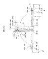
- the guide members 14 are mounted on the positive electrode terminal 105, the negative electrode terminal 106 and the dummy terminal 112 of the cover 108 on the worktable 2, respectively.
- the front ends 14c of the guide members 14 are inserted into the insertion groove 91 of the guide member attachment/detachment unit 9 formed at the holding plate 63 in order that the guide member 14 is held by the chuck parts 92.
- the placing plate 22 is rotated around the first rotary shaft 51 of the standing-up unit 5, and the holding plate 63 is also rotated around the second rotary shaft 64 of the temporary fixing unit 61 in order that the placing plate 22 and the holding plate 63 face each other.
- the concave parts 14b of the lower surfaces 14a of the guide members 14 inserted into the insertion parts 91 are fitted onto the front end small diameter parts 105e, 106e and 112e of the positive electrode terminal 105, the negative electrode terminal 106 and the dummy terminal 112 of the cover 108 fixed to the cover fixing part 22a.
- the chuck parts 92 of the guide member attachment/detachment unit 9 release the guide members 14.
- the holding plate 63 is rotated around the second rotary shaft 64 to return to its original position from the stood-up state
- the guide members 14 are separated from the insertion grooves 91 with the guide members 14 mounted on the front end small diameter parts 105e, 106e and 112e.
- the placing plate 22 is also rotated around the first rotary shaft 51 to return to its original position from the stood-up state.
- the positive electrode plate 101 and the negative electrode plate 102 are alternately stacked in order that the tabs 101b, 102b and 102c protrude in the same direction toward the P1 side in the P direction. That is, in the positive electrode plate conveyance part 31 and the negative electrode plate conveyance part 32 of the electrode plate conveyance unit 3, for example, the positive electrode plate conveyance part 31 is driven first.
- the positive electrode plate conveyance part 31 grips the positive electrode plate 101 conveyed to the corresponding electrode plate receiving position M1 by using the electrode plate hand part 31b, rotates an electrode plate conveyance arm part 31 a, and moves the positive electrode plate 101 over the electrode plate disposing part 22b of the worktable 2.
- the through-hole 101 c of the tab 101b is inserted onto the shaft part 105c of the positive electrode terminal 105, and the positive electrode plate 101 is arranged at the electrode plate disposing part 22b.
- the guide member 14 with a pointed tip and having an enlarged diameter toward the positive electrode terminal 105 is mounted on the positive electrode terminal 105, the shaft part 105c of the positive electrode terminal 105 can be easily inserted into the through-hole 101c of the tab 101b with minimal conveyance precision to enable precise position control thereof.
- the negative electrode plate conveyance part 32 grips the negative electrode plate 102 conveyed to the corresponding electrode plate receiving position M 1 by using the electrode plate hand part 32b, rotates the electrode plate conveyance arm part 32a, and moves the negative electrode plate 102 over the electrode plate disposing part 22b of the worktable 2.
- the negative electrode plate 102 is arranged on the electrode plate disposing part 22b, while the through-hole 102d of the tab 102b is inserted onto the shaft part 106c of the negative electrode terminal 106 and the through-hole 102e of the tab 102c is inserted onto the shaft part 112c of the dummy terminal 112.
- the guide members 14 are mounted on the negative electrode terminal 106 and the dummy terminal 112, respectively.
- the shaft parts 106c and 112c of the negative electrode terminals 106 are easily inserted into the through-holes 102d and 102e of the tabs 102b and 102c with minimal conveyance precision.
- the shaft part 105c of the corresponding positive electrode terminal 105, the shaft part 106c of the corresponding negative electrode terminal 106 and the shaft part 112c of the corresponding dummy terminal 112 are inserted into the corresponding through-holes 101c, 102d and 102e of the tabs 101 b, 102b and 102c, respectively.
- the positive electrode plate 101 and the negative electrode plate 102 are alternately stacked to form the electrode body 103 with keeping the shaft parts inserted into the corresponding through-holes.
- the positive electrode tab bundle 103a and the negative electrode tab bundles 103b and 103c of the electrode body 103 are supported to hang the positive electrode plates 101 and the negative electrode plates 102. That is, the standing-up unit 5 rotates the placing plate 22 around the first rotary shaft 51 to stand the placing plate 22 up.
- the shaft parts 105c, 106c and 112c of the positive electrode terminal 105, the negative electrode terminal 106 and the dummy terminal 112 are inserted into the through-holes 101c, 102d and 102e of the tabs 101 b, 102b and 102c of the positive electrode plate 101 and the negative electrode plate 102 respectively, the positive electrode tab bundle 103a and the negative electrode tab bundle 103b and 103c are hung with supported by the shaft parts 105c, 106c and 112c.
- the placing plate 22 may be stood-up vertically by the standing-up unit 5, it is preferable that the placing plate 22 is slightly inclined.
- each of the positive electrode plate 101 and the negative electrode plate 102 the tabs 101b, 102b and 102c are line-symmetrical with respect to the centerline L101 of the positive electrode plate 101 or the centerline L 102 of the negative electrode plate 102, that passes the coresponding center of gravity. Accordingly, each of the positive electrode plate 101 and the negative electrode plate 102 supported and hung by the positive electrode tab bundle 103a and the negative electrode tab bundles 103b and 103c is automatically positioned in order that directions of the centerlines L101 and L102 correspond each other due to gravity.
- the standing-up unit 5 may have a vibration induction part such as a vibration motor, and the like.
- the vibration induction part can cause vibrations to the positive electrode plates 101 and the negative electrode plates 102 on the placing plate 22, and a frictional force between the stacked positive electrode plate 101 and the stacked negative electrode plate 102 can be reduced by the vibrations to more effectively perform the positioning. Therefore, the stacking error is able to be prevented effectively.
- the positive electrode plates 101 and the negative electrode plates 102 are integrally fixed after they are stacked.
- the electrode body 103 is temporarily fixed by the temporary fixing unit 61. That is, as the holding plate 63 is rotated around the second rotary shaft 64 to face the placing plate 22, the electrode body 103 is sandwiched and pressed by the placing plate 22 and the holding plate 63. Accordingly, the positive electrode plates 101 and the negative electrode plates 102 are temporarily fixed so as not to be displaced from their stacked positions after the electrode plates are positioned by the hanging.
- the fixing tape 111 is adhered to the electrode body 103 by the tape adhering unit 62.
- the adhering mechanism 65 advances toward the worktable 2 by the advance/retreat mechanism 66 of the tape adhering unit 62 to insert the projecting plates 65b into the grooves 22c and 63a of the placing plate 22 and the holding plate 63. Then, a width between the pair of projecting plates 65b is made narrower. Therefore, the fixing tapes 111 are adhered to the edges of the electrode body 103 into a U shape, that is arranged between the projecting plates 65b. That is, the electrode body 103 is integrally fixed after positioning by the hanging.
- the guide members 14 are separated from the positive electrode terminal 105, the negative electrode terminal 106 and the dummy terminal 112 of the cover 108, respectively. That is, when the electrode body 103 is held by the placing plate 22 and the holding plate 63, the front end 14c of the guide member 14 is inserted into the insertion part 91 of the guide member attachment/detachment unit 9 (see FIG. 14 ). Then, while the front end 14c of the guide member 14 is kept to be inserted into the insertion part 9, the guide member 14 is held by the chuck parts 92. Next, the holding plate 63 is rotated around the first rotary shaft 51 to be spaced from the placing plate 22.
- the guide members 14 held by the chuck parts 92 are separated from the positive electrode terminal 105, the negative electrode terminal 106 and the dummy terminal 112, and retreated with the holding plate 63. Therefore, on the placing plate 22, the front ends of the shaft parts 105c, 106c and 112c protrude from the positive electrode tab bundle 103a and the negative electrode tab bundles 103b and 103c.
- the guide members 14 retreated with the holding plate 63 are used upon assembly of another new secondary battery 100.
- the placing plate 22 is rotated around the first rotary shaft 51 of the standing-up unit 5 to return the placing plate 22 to the state placed on the main stage 21.
- the positive electrode tab bundle 103a and the negative electrode tab bundles 103b and 103c are fixed to the corresponding terminals, respectively. That is, the pressing plate 7a of the tab fixing unit 7 is rotated around the third rotary shaft 7b to face the placing plate 22. Accordingly, the front end sides of the shaft parts 105c, 106c and 112c protruding from the tabs 101 b, 102b and 102c and also including the front end small diameter parts 105e, 106e and 112e are pressed and deformed to form the enlarged diameter parts 105d, 106d and 112d.
- the tabs 101b, 102b and 102c are fitted and fixed between the enlarged diameter parts 105d, 106d and 112d and the other ends 105c, 106c and 112c, although the corresponding shaft parts 105c, 106c, 112c are inserted into the through-holes 101c, 102d and 102e.
- the electrode body 103 is accommodated in the case body 107. That is, as shown in FIG. 18 , the pair of holding pieces 83b of the storing hand part 83 of the storing unit 8 are inserted into gaps formed at both sides of the cover 108 of the cover fixing part 22a in the Q direction to hold the cover 108. Then, as the storing hand part 83 is moved upward by the storing up/down positioning part 84, the cover 108 held by the storing hand part 83 is separated from the cover fixing part 22a so that the electrode body 103 constituted by the positive electrode plate 101 and the negative electrode plate 102 fixed to the positive electrode terminal 105, the negative electrode terminal 106 and the dummy terminal 112 of the cover 108 is further separated therefrom.
- the cover 108 and the electrode body 103 are hung by the storing unit 8 in a state held by the storing hand part 83, moved in the P direction, and conveyed to the storing position S. Then, at the storing position S, as the electrode body 103 is lowered by the storing up/down positioning part 84 from above the case body 107, the electrode body 103 is inserted into the case body 107 from the opening 107a thereof.
- the electrode body 103 and the cover 108 are further lowered by the storing up/down positioning part 84, the electrode body 103 is completely accommodated into the case body 107, the positive electrode tab bundle 103a and the negative electrode tab bundles 103b and 103c are folded to be accommodated in the case body 107, and the cover 108 is arranged at the opening 107a of the case body 107.
- the cover 108 can be rotated with respect to the storing hand part 83 by the contact plate 83c formed at the storing hand part 83 of the storing unit 8 as described above, the cover 108 is changed in direction to close the opening 107a of the case body 107 to be arranged at the opening 107a, closing the case body 107.
- the apparatus 1 for manufacturing the secondary battery of the embodiment in the positive electrode plate 101 and the negative electrode plate 102, one or two or more tabs are formed to be line-symmetrical with respect to the centerlines L101 and L102 of the main bodies 101a and 102a, and the plates are hung by standing-up unit 5, so that the positive electrode plate 101 and the negative electrode plate 102 can be precisely and effectively stacked to manufacture the secondary battery 100 without a stacking error, even when the plates have different sizes.
- the cover fixing part 22a is formed at the placing plate 22 of the worktable 2 at which the positive electrode plate 101 and the negative electrode plate 102 are stacked, the cover 108 conveyed by the cover conveyance unit 4 can be fixed to the cover fixing part 22a on the worktable 2.
- the positive electrode plate 101 and the negative electrode plate 102 are conveyed by the electrode plate conveyance unit 3, and the tabs 101b, 102b and 102c can be fixed onto the cover 108. Then, upon the hanging, the positive electrode plate 101 and the negative electrode plate 102 can be positioned with respect to each other by the standing-up unit 2 in a state supported by the cover 108.
- the positive electrode plate 101 and the negative electrode plate 102 are conveyed by the electrode plate conveyance unit 3 to pass the corresponding positive electrode terminal 105 or negative electrode terminal 106 through the through-holes 101 c, 102d and 102e of the tabs 101b, 102b and 102c
- the guide members 14 having a conical shape are fixed to the positive electrode terminal 105 and the negative electrode terminal 106, the positive electrode terminal 105 or the negative electrode terminal 106 may easily pass through the through-holes 101c, 102d and 102e of the tabs 101b, 102b and 102c with minimal conveyance precision.
- the guide members 14 are separated by the guide member attachment/detachment unit 9, and thus, the guide members 14 do not interfere with the following operation of the tab fixing unit 7.
- FIG. 20 shows another embodiment of a secondary battery.
- a case 201 in a secondary battery 200 of the embodiment, has a case body 202 having an opening 202a at one side in a stacking direction X, and a cover 203 configured to close the opening 202a. Because the cover 203 is configured to close the opening 202a, the cover 203 has an area larger than a positive electrode plate 101 and a negative electrode plate 102 accommodated in the case body 202.
- a positive electrode terminal 105, a negative electrode terminal 106 and a dummy terminal 112 are formed at the cover 203.
- the positive electrode terminal 145, the negative electrode terminal 106 and the dummy terminal 112 passing through the cover 203 also project in the X direction.
- main bodies 101a and 102a as well as tabs 101b, 102b and 102c are placed on the cover 203 such that the positive electrode plate 101 and the negative electrode plate 102 can be alternately stacked. Accordingly, the cover 203 and the electrode body 103 can be integrally and easily treated.
- the electrode body 103 is accommodated in the case body 107, because there is no need to convey/insert the hanging electrode body 103 and it is sufficient to cover the case body 202 from above the cover 203, an operation becomes easier.
- the tabs 101b, 102b and 102c are not folded but may be arranged without variation in direction. As a result, in a state accommodated in the case 201, there is no chance of damage to the tabs 101b, 102b and 102c due to generation of a tensile or compression stress caused by bending the tabs.
- the positive electrode plate 101 has one tab 101b and the negative electrode plate 102 has two tabs 102b and 102c
- the present invention is not limited thereto.
- the positive electrode plate 101, as well as the negative electrode plate 102 may also have two tabs 101b and 101d, one of which may be referred to as a connecting tab and the other of which may be referred to as a dummy tab.
- the number of tabs is not limited to 2 but may be 3 or more.
- the positive electrode plate and the negative electrode plate are at least stacked at different positions.
- the positive electrode plate and the negative electrode plate have at least one or two tabs, which do not overlap each other, and may be arranged to be line-symmetrical with respect to the centerlines L101 and L102 of the electrode plates.
- the centerlines of the electrode plates coincide with each other due to gravity upon the hanging such that the electrode plates can be positioned and stacked with high precision.
- the secondary battery when the secondary battery is assembled to drive an electric motor of a movable body such as a vehicle and vibration in a centerline direction occurs, because a rotational force to a positive electrode main body at a connecting part between the positive electrode main body and the tab of the positive electrode plate is not occurred or prevented, and because a rotational force to a negative electrode main body at a connecting part between the negative electrode main body and the tab of the negative electrode plate is not occurred or prevented, a breakage of the connecting part can be prevented and thus a failure of the secondary battery can be prevented.
- the tab may be designed to have a larger width than the tab of the other electrode plate.
- the tab is arranged to be line-symmetrical with respect to the centerline of the positive electrode plate or the negative electrode plate including the pouch-type separator.
- the present invention is not limited thereto.
- the positive electrode plate 101 and the negative electrode plate 102 may be stacked and then the tabs 101b, 102b and 102c may be supported and hung by another support member, the stacked state of the electrode body 103 positioned by the hanging is fixed, and then the positive electrode terminal 105, the negative electrode terminal 106 and the dummy terminal 112 of the cover 108 may be connected to the positive electrode tab bundle 103a and the negative electrode tab bundles 103b and 103c.
- the tab 102c Upon connection to the terminals, while the tab 102c, which is a dummy tab, is connected to the terminal using the dummy terminal 112, the tab 102c may not be connected to the terminal.
- the guide members 14 are mounted to the terminals before the positive electrode plate 101 and the negative electrode plate 102 are stacked, the present invention is not limited thereto.
- the guide members may be already mounted on the cover received at the cover receiving position. In this case, there is no need to provide the guide member attachment/detachment unit 9 configured to attach/detach the guide members 14, and it is sufficient to provide a guide member removal unit configured to remove the guide members 14.
- the used guide members 14 have a conical shape, various shapes of guide members can be applied.
- the guide member may have a conical shape in which a ridge arranged at an upper side thereof is substantially parallel to an axial line of the terminal during the hanging.
- the stacking may be easily performed, and positioning precision of the positive electrode plate 101 and the negative electrode plate 102 can be further improved during the hanging.
- the secondary battery manufacturing apparatus of the present invention even when a positive electrode plate and a negative electrode plate of the secondary battery have different sizes, the secondary battery in which the electrode plates are precisely positioned and stacked can be manufactured. According to the secondary battery of the present invention, it is possible to prevent a failure such as breakage of a connecting part between a positive electrode main body and a tab of the positive electrode plate and a connecting part between a negative electrode main body and a tab of the negative electrode plate.
Landscapes
- Chemical & Material Sciences (AREA)
- Chemical Kinetics & Catalysis (AREA)
- Electrochemistry (AREA)
- General Chemical & Material Sciences (AREA)
- Engineering & Computer Science (AREA)
- Manufacturing & Machinery (AREA)
- Secondary Cells (AREA)
- Sealing Battery Cases Or Jackets (AREA)
- Connection Of Batteries Or Terminals (AREA)
Abstract
Disclosed is a secondary cell provided with an electrode body in which a positive plate and a negative plate are alternately stacked with a separator therebetween, a case that houses the aforementioned electrode body, and a cover that is provided with a positive terminal and a negative terminal and fits in the aforementioned case, wherein the aforementioned positive plate is equipped with a roughly plate-like main positive electrode body and a first tab that is disposed axisymmetrically with respect to the axis of the center of gravity of the aforementioned positive plate and that is connected to the aforementioned main positive electrode body and the aforementioned positive terminal, the aforementioned negative plate is equipped with a roughly plate-like main negative electrode body and a second tab that is disposed axisymmetrically with respect to the axis of the center of gravity of the aforementioned negative plate and that is connected to the aforementioned main negative electrode body and the aforementioned negative terminal, and the aforementioned first and second tabs are disposed in positions that do not mutually overlap during stacking.
Description
- The present invention relates to a secondary battery in which a positive electrode plate and a negative electrode plate are stacked, and a secondary battery manufacturing apparatus for manufacturing the secondary battery.
This patent application claims priority of Japanese Patent Application No.2010-030421, filed on February 15, 2010 - A stack-type secondary battery has an electrode body in which a positive electrode plate and a negative electrode plate with tabs formed at edges thereof are alternately stacked, and a positive electrode terminal and a negative electrode terminal correspondingly connected to the tabs of the positive electrode plate and the negative electrode plate, respectively. Here, because the positive electrode plate and the negative electrode plate should be insulated from each other in a stacked state, a separator formed of an insulating material is arranged between the plates (e.g., see Patent Document 1). In addition, the separator may have a pouch shape to surround the negative electrode plate to be insulated from the positive electrode plate (e.g., see Patent Document 2).
- However, when a positional error occurs during stacking the positive electrode plate and the negative electrode plate of the electrode body, Li deposition is caused by an uneven reaction, or charge/discharge performance is affected by a reduction of reaction area. Further, when the error occurs, although the separator should have been interposed between the positive electrode plate and the negative electrode plate before the error occurs, the positive electrode plate and the negative electrode plate adjacent to the positive electrode plate may contact each other and cause a short circuit. Accordingly, in a process of manufacturing the electrode body, the positive electrode plate and the negative electrode plate should be precisely stacked, and in general, the positive electrode plate and the negative electrode plate are alternately stacked with being positioned by a positioning pin, etc.
- [Patent Document 1] Japanese Patent Application Laid-Open No.
2006-339054 2003-45498 - However, the size of the positive electrode plate and the size of the negative electrode plate as described in
Patent Documents Patent Document 2, the total size for one electrode plate becomes larger because the separator is rimmed to form the pouch. Accordingly, while one electrode plate having a larger size between the positive electrode plate and the negative electrode plate can be precisely positioned by a pin, the other electrode plate having a smaller size cannot be positioned by the pin due to interference with the previously stacked electrode plate. Therefore, to position the electrode plate accurately, it is needed to use a conveyor having high accuracy to position the electrode plate. As a result, an electrode body cannot be formed, that the electrode plates are arranged with high accuracy. Even when the electrode body can be formed, it is needed to have long time to position the electrode plates. Therefore, the cost of its production may be increased. - The present invention has been made in view of the above-described circumstances, and an object of the invention is to provide a secondary battery without the positional error substantially when the size of the positive electrode plate and the size of the negative electrode plate are different from each other, which is achieved by precise positioning and stacking both of the electrode plates, and an apparatus for manufacturing the same secondary battery.
- To achieve the above-described object, a secondary battery manufacturing apparatus of the present invention includes: a cover fixing part to fix a cover having shaft parts of a positive electrode terminal and a negative electrode terminal in order that the shaft parts are directed upward; a positive electrode plate conveyance part to convey a positive electrode plate having a tab in which a first through-hole is formed and which is arranged to be line-symmetrical with respect to a centerline of the positive electrode plate, to the cover fixing part; a positive electrode plate disposing part to insert the first through-hole of the conveyed positive electrode plate into the shaft part of the positive electrode terminal; a negative electrode plate conveyance part to convey a negative electrode plate having a tab in which a second through-hole is formed and which is arranged to be line-symmetrical with respect to a centerline of the negative electrode plate, to the cover fixing part; a negative electrode plate disposing part to insert the second through-hole of the conveyed negative electrode plate into the shaft part of the negative electrode terminal and to stack the negative electrode plate on the positive electrode plate; and a standing-up unit to stand the cover fixed by the cover fixing part up in order that the stacked positive electrode plate and the stacked negative electrode plate are hung and positioned.
- According to the above configuration, in a state in which the cover stood-up by the standing-up unit supports the tabs, the positive electrode plate and the negative electrode plate are hung. Here, because the tab is arranged to be line-symmetrical with respect to a centerline (to be defined later), the positive electrode plate and the negative electrode plate supported and hung by the tab coincide with directions of the centerlines thereof to be automatically positioned.
Therefore, it is possible to manufacture the secondary battery in which both of the electrode plates are precisely positioned and stacked. - In addition, a secondary battery of the present invention includes: an electrode body in which a positive electrode plate and a negative electrode plate are alternately stacked through a separator; a case to store the electrode body; and a cover having a positive electrode terminal and a negative electrode terminal and fitted to the case, wherein the positive electrode plate includes a positive electrode main body having a substantial plate shape, and a first tab arranged to be line-symmetrical with respect to a centerline of the positive electrode plate and connected to the positive electrode main body and the positive electrode terminal, the negative electrode plate includes a negative electrode main body having a substantial plate shape, and a second tab arranged to be line-symmetrical with respect to a centerline of the negative electrode plate and connected to the negative electrode main body and the negative electrode terminal, and the first tab and the second tab are arranged not to overlap each other when the tabs are stacked.
- According to the above configuration, in the positive electrode plate and the negative electrode plate, the tabs thereof are arranged to be line-symmetrical with respect to centerlines thereof. Accordingly, the electrode plates are precisely positioned and stacked.
In addition, for example, when the secondary battery is assembled to drive an electric motor of a movable body such as an electric vehicle and vibration in a centerline direction occurs to vertically shake a surface of the cover, application of a rotational force to a positive electrode main body at a connecting part between the positive electrode main body and the tab of the positive electrode plate is prevented and application of a rotational force to a negative electrode main body at a connecting part between the negative electrode main body and the tab of the negative electrode plate is also prevented.
As a result, a failure of the secondary battery such as a breakage of the connecting part can be prevented. - According to a secondary battery manufacturing apparatus of the present invention, when a secondary battery constituted by a positive electrode plate and a negative electrode plate having different sizes is manufactured, the secondary battery can be manufactured with the electrode plates precisely positioned and stacked.
According to the secondary battery of the present invention, the secondary battery in which the positive electrode plates and the negative electrode plates are precisely stacked can be provided. -
-
FIG. 1 is a perspective view of a secondary battery in accordance with an embodiment of the present invention, a portion of which is partially cut; -
FIG. 2 is a cross-sectional view along line A-A ofFIG 1 ; -
FIG. 3 is a cross-sectional view along line B-B ofFIG. 1 ; -
FIG. 4 is a view for explaining a state in that positive electrode plates and negative electrode plates are stacked in accordance with the embodiment of the present invention; -
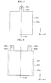
FIG. 5 is a front view of the positive electrode plate of the secondary battery in accordance with the embodiment of the present invention; -
FIG. 6 is a front view of the negative electrode plate of the secondary battery in accordance with the embodiment of the present invention; -
FIG. 7 is a perspective view schematically showing a secondary battery manufacturing apparatus in accordance with the embodiment of the present invention; -
FIG. 8 is a cross-sectional view specifically showing a guide member of the secondary battery manufacturing apparatus in accordance with the embodiment of the present invention; -
FIG. 9 is a cross-sectional view specifically showing a guide member attachment/detachment unit of the secondary battery manufacturing apparatus in accordance with the embodiment of the present invention; -
FIG. 10 is a cross-sectional view specifically showing a storing unit of the secondary battery manufacturing apparatus in accordance with the embodiment of the present invention; -
FIG. 11 is a view for explaining a cover conveyance operation of the secondary battery manufacturing apparatus in accordance with the embodiment of the present invention; -
FIG. 12 is a view for explaining a guide member mounting operation of the secondary battery manufacturing apparatus in accordance with the embodiment of the present invention; -
FIG. 13 is a view for explaining a stacking operation of the secondary battery manufacturing apparatus in accordance with the embodiment of the present invention; -
FIG. 14 is a view for explaining a hanging operation of the secondary battery manufacturing apparatus in accordance with the embodiment of the present invention; -
FIG. 15 is a view for explaining a stacking/fixing operation of the secondary battery manufacturing apparatus in accordance with the embodiment of the present invention; -
FIG. 16 is a view for explaining a guide member removal operation of the secondary battery manufacturing apparatus in accordance with the embodiment of the present invention; -
FIG. 17 is a view for explaining a terminal fixing operation of the secondary battery manufacturing apparatus in accordance with the embodiment of the present invention; -
FIG. 18 is a view for explaining a storing operation of the secondary battery manufacturing apparatus in accordance with the embodiment of the present invention; -
FIG. 19 is a view for explaining an operation of the secondary battery manufacturing apparatus in accordance with the embodiment of the present invention, in which an opening of a case body is closed by a cover; -
FIG. 20 is an exploded side view of a secondary battery in accordance with another embodiment of the present invention; -
FIG. 21 is a front view showing another example of the positive electrode plate and the negative electrode plate of the secondary battery in accordance with the embodiment of the present invention; and -
FIG. 22 is a side view showing another example of the guide member of the secondary battery in accordance with the embodiment of the present invention. - Hereinafter, an embodiment of the present invention will be described with reference to
FIGS. 1 to 15 .FIGS. 1 to 6 show a secondary battery of the embodiment. As shown inFIGS. 1 to 3 , asecondary battery 100 of the embodiment includes anelectrode body 103 in which apositive electrode plate 101 and anegative electrode plate 102 are alternately stacked, acase 104 configured to accommodate theelectrode body 103, and apositive electrode terminal 105 and anegative electrode terminal 106 formed in thecase 104 to correspond to thepositive electrode plate 101 and thenegative electrode plate 102 therein. Thecase 104 includes acase body 107 having an opening 107a in a Z-axis direction perpendicular to an X-axis direction in which theelectrode body 103 is stacked, and acover 108 configured to close the opening 107a of thecase body 107. In addition, thepositive electrode terminal 105 and thenegative electrode terminal 106 are attached to thecover 108 via aninsulating sleeve 109. Oneend 105a of thepositive electrode terminal 105 and oneend 106a of thenegative electrode terminal 106 project to the outside of thecase 104, and theother end 105b of thepositive electrode terminal 105 and theother end 106b of thenegative electrode terminal 106 project to the inside of thecase 104 and are correspondingly connected to thepositive electrode plate 101 and thenegative electrode plate 102, respectively. - The
positive electrode plate 101 and thenegative electrode plate 102 havemain bodies tabs main bodies tabs positive electrode plate 101 and thenegative electrode plate 102 are perpendicular to the X-axis direction, which is a direction for stacking the electrode plates (herein, it is called as the "stacking direction"), and project in the Z-axis direction, which is a direction toward thepositive electrode terminal 105 and thenegative electrode terminal 106 in thecase 104. In thepositive electrode plate 101 and thenegative electrode plate 102, themain body 102a of thenegative electrode plate 102 is covered by aseparator 110 formed of an insulating material, and thus, thepositive electrode plate 101 and thenegative electrode plate 102 are stacked on each other with theseparator 110 arranged between them to insulate the electrode plates, for forming theelectrode body 103.
In addition, fixingtapes 111 formed of an insulating material are adhered to edges of the electrode body 143, and thus, thepositive electrode plate 101 and thenegative electrode plate 102 are fixed not to be dislocated. In this embodiment, the fixingtapes 111 are adhered to both edges of theelectrode body 103, in which the electrode plates (i.e., thepositive electrode plate 101 and the negative electrode plate 102) are sequentially stacked in the X-axis direction perpendicular to the Y-axis direction and the Z-axis direction. - Further, as shown in
FIG. 4 , when the electrode plates are viewed from the X Direction, thetabs 101b of thepositive electrode plate 101 coincide each other, and thetabs negative electrode plate 102 coincide each other, although thetabs 101b and thetabs electrode body 103 is formed, a positive electrode tab bundle 143a is formed by gathering thetabs 101b of thepositive electrode plates 101, and negative electrode tab bundles 143b and 103c are formed by respectively gatering thetabs 102b and the tabs 142c of thenegative electrode plates 102. Here, thetabs hole electrode tab bundle 103a and the negative electrode tab bundles 103b and 103c are formed, the positions of the through-holes 101 c are corresponded each other, the positions of the through-holes 102d are corresponded each other, and the positions of the through-holes 102e are corresponded each other. - Furthermore, as shown in
FIGS. 5 and 6 , thetabs main body 101 a and which is along the Z-axis direction, or a centerline
L 102 which is on the center of gravity of themain body 102a and which is along the Z-axis direction, at one or two or more positions. Specifically, thetab 101b, that is only one tab for thepositive electrode plate 101, is arranged at themain body 101 a of thepositive electrode plate 101 to be line-symmetrical with respect to the centerline L101 in the Z-axis direction. In addition, thetabs main body 102a of thenegative electrode plate 102 to be line-symmetrical with respect to the center line L102 in the Z-axis direction. Further, here, the centerline is a line along a projecting direction (i.e., the Z-axis direction) of the tab, which passes through the center of the gravity of the positive electrode plate or the negative electrode plate. - As shown in
FIGS. 1 and2 , thetab 101b of thepositive electrode plate 101 works as a connecting tab, and thetabs 101b are gathered to form the positiveelectrode tab bundle 103a. Meanwhile, ashaft part 105c inserted into the through-hole 101c, and alarge diameter part 105d having a diameter enlarged in a flange shape from a front end of theshaft part 105c, are formed at theother end 105b of the positive electrode terminal 145. The positiveelectrode tab bundle 103a in which theshaft part 105c is inserted into the through-hole 101c is sandwiched between thelarge diameter part 105d and theother end 105b, and fixed thereto. - Similarly, the
tab 102b of twotabs negative electrode plate 102 works as a connecting tab, and thetabs 102b are gathered to form the negativeelectrode tab bundle 103b. Meanwhile, ashaft part 106c inserted into the through-hole 102d, and alarge diameter part 106d having a diameter enlarged in a flange shape from a front end of theshaft part 106c, are formed at theother end 106b of thenegative electrode terminal 106. The negativeelectrode tab bundle 103b in which theshaft part 106c is inserted into the through-hole 102d is sandwiched between thelarge diameter part 106d and theother end 106b, and fixed thereto. - In addition, as shown in
FIGS. 1 and3 , in thecover 108 for thecase 104, adummy terminal 112 is formed at a corresponding position to thetab 102c of twotabs negative electrode plate 102. Thedummy terminal 112 has only theother end 112b corresponding to theother end 106b of thenegative electrode terminal 106, and has no portion corresponding to thefront end 106a protruding to the outside of thecase 104.
Further, ashaft part 112c and alarge diameter part 112d are formed at theother end 112b of thedummy terminal 112, similar to thepositive electrode terminal 105 and thenegative electrode terminal 106. Theother tab 102c of twotabs negative electrode plate 102 is a dummy tab, and thetabs 102c are gathered to form the negativeelectrode tab bundle 103c. And theshaft part 112c of thedummy terminal 112 is inserted into the through-hole 102e to sandwich and to fix the dummy tab between theother end 112b and thelarge diameter part 112d. In addition, thelarge diameter parts positive electrode terminal 105, thenegative electrode terminal 106 and thedummy terminal 112 are formed by deforming parts of the correspondingshaft parts - Hereinafter, a secondary
battery manufacturing apparatus 1 for manufacturing thesecondary battery 100 will be described.
FIG. 7 shows the secondarybattery manufacturing apparatus 1 of the embodiment. As shown inFIG. 7 , the secondarybattery manufacturing apparatus 1 includes aworktable 2 on which apositive electrode plate 101 and anegative electrode plate 102 are placed, an electrodeplate conveyance unit 3 to convey thepositive electrode plate 101 and thenegative electrode plate 102 to theworktable 2 for forming anelectrode body 103, a cover conveyance unit 4 to convey acover 108 to theworktable 2, a standing-upunit 5 to stand theelectrode body 103 up, a stacking/fixingunit 6 to integrally fix the stackedpositive electrode plate 101 andnegative electrode plate 102, atab fixing unit 7 to fixtabs storing unit 8 to store theelectrode body 103 into acase 104. - The
worktable 2 includes amain stage 21, and a placingplate 22 arranged on themain stage 21 and on which thepositive electrode plate 101 and thenegative electrode plate 102 are placed. The placingplate 22 is placed in order that the Z-axis direction, in which thetabs FIG. 7 .
The placingplate 22 includes acover fixing part 22a having a concave part concaved in order that thecover 108 is fitted thereinto, and an electrodeplate disposing part 22b arranged at a P2 direction in the P direction from thecover fixing part 22a and on which thepositive electrode plate 101 and thenegative electrode plate 102 are placed.
The concave part having substantially the same width in the P direction as a width in the X-axis direction (seeFIG. 1 ) of thecover 108 is formed at thecover fixing part 22a, in order that thecover 108 is fitted thereinto. A longitudinal direction of the concave part is directed to a Q direction perpendicular to the P direction. The concave part is designed to have a length larger than a width in the Y-axis direction (seeFIG. 1 ) of thecover 108, in order that thecover 108 can be fitted into thecover fixing part 22a while thecover 108 is gripped by the cover conveyance unit 4.
In addition, the electrodeplate disposing part 22b has agroove 22c formed in the Q direction perpendicular to the P direction. Thegroove 22c is formed to pass through both edges of the placingplate 22. In this embodiment, two grooves are arranged in the P direction. - Further, a first
rotary shaft 51 is arranged along the Q direction at an edge of the placingplate 22 in the P direction, and a rotation drive part (hereinafter, it is called as a first rotation drive part) is arranged to rotate the firstrotary shaft 51, although the rotation drive part is not shown. The placingplate 22 can be rotated to stand up with thestacked electrode body 103, while thecover fixing part 22a is arranged at the upper side of the placingplate 22. The standing-upunit 5 to stand theelectrode body 103 up is formed by the firstrotary shaft 51 and the first rotation drive part. - The electrode
plate conveyance unit 3 includes a positive electrodeplate conveyance part 31 to convey thepositive electrode plate 101, and a negative electrodeplate conveyance part 32 to convey thenegative electrode plate 102, which are arranged at both sides of theworktable 2 in the Q direction. The positive electrodeplate conveyance part 31 and the negative electrodeplate conveyance part 32 have electrode plateconveyance arm parts plate disposing part 22b of theworktable 2. At the positions M1 and M2, the correspondingpositive electrode plate 101 or thenegative electrode plate 102 is received. Further, the electrodeplate conveyance unit 3 includes electrodeplate hand parts conveyance arm parts positive electrode plate 101 or thenegative electrode plate 102. And the electrodeplate conveyance unit 3 includes electrode plate up/downpositioning parts plate hand parts plate hand parts positive electrode plate 101 or thenegative electrode plate 102 by the vacuum suction. - The
positive electrode plate 101 and thenegative electrode plate 102 are sequentially conveyed to the corresponding electrode plate receiving positions M1 and M2 by, for example, electrode plate-conveyingconveyor belts
Thepositive electrode plate 101 and thenegative electrode plate 102 are formed by punching an electrode sheet having a large length before the conveyance. At this time, the through-holes are simultaneously formed at the tabs when the main bodies of the electrode plates are formed by the punching. Specifically, the main bodies, the tabs and the through-holes are able to be formed by the same mold.
In the related art, after the positive electrode plate and the negative electrode plate are stacked, the through-holes are formed. Therefore, scrap metals like burrs may be mixed in the battery and cause a failure of the battery. However, as described above, because the through-holes are formed simultaneously when thepositive electrode plate 101 and thenegative electrode plate 102 are formed, the burrs do not be formed. This is because the burrs cannot be easily generated when only one tab is punched and the through-hole is formed, although the burrs may be easily generated when the plurality of tabs are gathered and punched.
In addition, because the through-holes are formed in the positive electrode plate and the negative electrode plate by using the same mold, when one of the two types of the electrode plates are considered, positions of the through-holes formed in the tabs of the plurality of stacked positive electrode plates (or the plurality of negative electrode plates) may be unified. That is, a position error of the through-holes of the tabs of the plurality of electrode plates can be prevented respectively. - The electrode plate-conveying
conveyor belts positive electrode plate 101 ornegative electrode plate 102 to the electrode plate receiving positions M1 and M2, in order that the direction in which thetabs positive electrode plate 101 or thenegative electrode plate 102 is conveyed and placed on theworktable 2 from the electrode plate receiving positions M1 and M2 by the corresponding positive electrodeplate conveyance part 31 or the corresponding negative electrodeplate conveyance part 32.
More specifically, in this embodiment, as the electrode plateconveyance arm parts plate conveyance part 31 and the negative electrodeplate conveyance part 32 are rotated about 90° around the rotary shafts thereof, the arm parts can move to the electrodeplate disposing part 22a of theworktable 2 from the electrode plate receiving positions M1 and M2. - The cover conveyance unit 4 is arranged adjacent to the place of the
worktable 2, where thetabs conveyance guide part 41 arranged along the P direction, acover slider 42 that is movable along the coverconveyance guide part 41 between a cover receiving position N in which thecover 108 is received and theworktable 2, acover hand part 43 arranged at thecover slider 42 to attach/detach thecover 108, and a cover up/down positioningpart 44 to adjust the position of thecover hand part 43 with respect to thecover slider 42 in the R direction. - The
cover hand part 43 has abase part 43a along the Q direction, and a pair of holdingpieces 43b that are slidable along thebase part 43a. A distance between the pair of holdingpieces 43b can be reduced along thebase part 43a to hold thecover 108. Thecover hand part 43 may be formed with a suction pad by using the vacuum suction, similar to the cases of thepositive electrode plate 101 or thenegative electrode plate 102. - The
covers 108 are sequentially conveyed to a cover receiving position N by, for example, a cover-conveyingconveyor belt 13. In addition, thecover 108 is conveyed by the cover-conveyingconveyor belt 13, while theinner surface 108a of thecover 108 is directed upward.
When thecover 108 is conveyed to the cover receiving position N by the cover-conveyingconveyor belt 13, thepositive electrode terminal 105, thenegative electrode terminal 106 and thedummy terminal 112 of thecover 108 have noenlarged diameter parts shaft parts small diameter parts shaft parts enlarged diameter parts - In addition, the stacking/fixing
unit 6 includes atemporary fixing unit 61 to temporarily fix theelectrode body 103 stood-up by the standing-upunit 5, andtape adhering unit 62 to fix the temporarily fixedelectrode body 103 by using a fixingtape 111.
Thetemporary fixing unit 61 includes a holdingplate 63 arranged adjacent to the placing plate 22 (i.e., the P2 direction in the P direction) on themain stage 21 of theworktable 2, and a secondrotary shaft 64 arranged at an edge of the holdingplate 63 along the Q direction to rotate the holdingplate 63 on themain stage 21, although the edge is one edge existed to the P1 direction between two edges of the holdingplate 63 existed in the P direction. Further, thetemporary fixing unit 61 includes a rotation drive part (hereinafter, it is called as a second rotation drive part) to rotate the secondrotary shaft 64, although the second rotation drive part is not shown. The holdingplate 63 is arranged at a position in order that theelectrode body 102 on the placingplate 22 can be sandwiched between the holdingplate 63 and the placingplate 22 stood-up by the standing-upunit 5, when the holdingplate 63 is rotated around the secondrotary shaft 64. In addition, agroove 63a is formed on the holdingplate 63 at a position opposite to thegroove 22c formed on the placingplate 22. Thegroove 63a is formed to pass through the both edges along the Q direction. - Further, two of the
tape adhering units 62 are arranged at both sides of theworktable 2 to sandwich theworktable 2 in the Q direction. Thetape adhering unit 62 includes an adheringmechanism 65 to adhere the fixingtape 111 to theelectrode body 103, and an advance/retreat mechanism 66 to move the adheringmechanism 65 forward to and backward from theworktable 2 in the Q direction. The advance/retreat mechanism 66 includes an advance/retreat guide part 66a arranged in the Q direction, and an advance/retreat member 66b having the the adheringmechanism 65 formed at a front end thereof and moving forward and backward by the advance/retreat guide part 66a in the Q direction. Two adheringmechanisms 65 are respectively arranged at upper part and a lower part of the advance/retreat member 66b corresponding to thegroove 22c of the placingplate 22 and thegroove 63a of the holdingplate 63. - The adhering
mechanism 65 includes abase piece 65a having a length corresponding to a thickness of theelectrode body 103 and being arranged in the P direction, and a pair of projectingpieces 65b protruding from both ends of thebase piece 65a in the Q direction. The U shape is formed by thebase piece 65a and the pair of projectingpieces 65b.
As the adheringmechanism 65 moves toward theworktable 2 by the advance/retreat mechanism 66, the projectingpieces 65b can be inserted into thegroove 22c of the placingplate 22 stood-up by the standing-upunit 5 and thegroove 63a of the holdingplate 63 rotated to face the placingplate 22, respectively. Further, the projectingpieces 65b are able to slide along thebase piece 65a.
The fixingtape 111 is arranged inside of the U-shaped portion to be extended from the one projectingpiece 65b to the other projectingpiece 65b via thebase piece 65a. An adhering part of the fixingtape 111 is directed toward the inside of the U-shaped portion.
According to this configuration, after the projectingpieces 65b are inserted into thegrooves 63a respectively, the pair of projectingpieces 65b are slid to each other to press and sandwich theelectrode body 103. Therefire, the fixingtape 111 is adhered to theelectrode body 103. - In the holding
plate 63, a guide member attachment/detachment unit 9, which attaches and detaches a guide member 14 (to be described later) to and from positions corresponding to thepositive electrode terminal 105, thenegative electrode terminal 106 and thedummy terminal 112 of thecover 108 fixed to thecover fixing part 22a, is formed at a position corresponding to thecover fixing part 22a formed at the placingplate 22.
Here, as shown inFIG. 8 , in this embodiment, theguide member 14 has a conical shape. Theguide member 14 includes abottom surface 14a, which is a base end, having aconcave part 14b fitted onto the front endsmall diameter parts positive electrode terminal 105, thenegative electrode terminal 106 and thedummy terminal 112 of thecover 108, in which theenlarged diameter parts bottom surface 14a of theguide member 14 is set to be substantially the same as the diameters of theshaft parts - As shown in
FIG 9 , specifically, the guide member attachment/detachment unit 9 includes aninsertion groove 91 into which afront end 14c of theguide member 14 is inserted, and chuckparts 92 formed inside theinsertion groove 91 and being able to sandwich thefront end 14c of the insertedguide member 14. As shown inFIG. 7 , when the placingplate 22 and the holdingplate 63, that are stood-up by the standing-upunit 5 are faced to each other, theinsertion grooves 91 are faced to thepositive electrode terminal 105, thenegative electrode terminal 106 and thedummy terminal 112 of thecover 108 fitted into thecover fixing part 22a of the placingplate 22. Therefore, theguide members 14 at the terminals are inserted into theinsertion grooves 91 corresponding thereto, and theguide members 14 can be delivered and received between the terminals and thechuck parts 92 inside theinsertion grooves 91. - As shown in
FIG. 7 , thetab fixing unit 7 includes apressing plate 7a arranged at the P1 side of the placingplate 22 in the P direction, a thirdrotary shaft 7b arranged at an edge of the P1 side of the placingplate 22 in the P direction and being able to rotate thepressing plate 7a about the Q direction as an axial, and a rotation drive part (i.e., a third rotation drive part) (not shown) to rotate the thirdrotary shaft 7b.
As described later, after thepositive electrode plate 101 and thenegative electrode plate 102 are stacked on the placingplate 22 and theguide member 14 is separated from thepositive electrode terminal 105, thenegative electrode terminal 106 and the dummy terminal, thepressing plate 7a is rotated around the thirdrotary shaft 7b. And then, the front ends of theshaft parts positive electrode terminal 105, thenegative electrode terminal 106 and thedummy terminal 112 of thecover 108 fixed to thecover fixing part 22a are pressed and caulked by thepressing plate 7a to form theenlarged diameter parts - The storing
unit 8 includes an storingguide part 81 arranged in the P direction, and an storingslider 82 movable to an storing position S, at which theelectrode body 103 is to be stored in thecase body 107 from the upperside of theworktable 2. Further, the storingunit 8 includes an storinghand part 83 arranged at the storingslider 82 to attach and detach thecover 108, and an storing up/down positioningpart 84 to adjust the position of the storinghand part 83 with respect to the storingslider 82 in the R direction.
Here, thecase bodies 107 are sequentially conveyed to the storing position S by, for example, a case body-conveyingconveyor belt 16. At this time, theopening 107a is arranged to be directed upward. - The storing
hand part 83 includes abase part 83a arranged in the Q direction, and a pair of holdingpieces 83b that are slidable along thebase part 83a. When a spacing distance between the pair of holdingpieces 83b is reduced along thebase part 83a, thecover 108 can be held in the Q direction.
Here, as shown inFIG. 10 ,contact plates 83c are rotatably supported at positions to hold thecover 108, and arranged at the pair of holdingpieces 83b of the storinghand part 83, respectively. Accordingly, when thecover 108 is held by the pair of holdingpieces 83b, thecontact plates 83c come in contact with thecover 108 in order that a direction of thecover 108 with respect to the holdingpieces 83b can be changed by rotation of thecontact plates 83c. - Hereinafter, an operation of the
apparatus 1 for manufacturing thesecondary battery 100 of the embodiment will be described with reference toFIGS. 11 to 18 .
First, as a preparation process, thepositive electrode plate 101 and thenegative electrode plate 102 are prepared, and thecover 108 and thecase body 107 are also prepared. Then, the preparedpositive electrode plate 101 and thenegative electrode plate 102 are sequentially conveyed to the corresponding electrode plate receiving positions M1 or M2 respectively by the corresponding electrode plate-conveyingconveyor belts prepared cover 108 is sequentially conveyed to the cover receiving position N by the cover-conveyingconveyor belt 13. Next, theprepared case body 107 is sequentially conveyed to the storing position S by the case body-conveyingconveyor belt 16.
Here, in thecover 108 conveyed to the cover receiving position N, thepositive electrode terminal 105, thenegative electrode terminal 106 and thedummy terminal 112 do not have theenlarged diameter parts small diameter parts shaft parts - In addition, as shown in
FIG. 11 , thecover 108, conveyed to the cover receiving position N by the cover conveyance unit 4, is conveyed to thecover fixing part 22a of the placingplate 22 of theworktable 2. That is, at the cover receiving position N, thecover 108 is held by the pair of holdingpieces 43b of the cover conveyance unit 4. Then, the heldcover 108 is conveyed over thecover fixing part 22a on the placingplate 22 of theworktable 2 in the P direction. Next, when thecover 108 is lowered by the cover up/down positioningpart 44, thecover 108 is fitted and fixed to thecover fixing part 22a in order that theinner surface 108a of thecover 108 is received upward. - Next, as shown in
FIG. 12 , theguide members 14 are mounted on thepositive electrode terminal 105, thenegative electrode terminal 106 and thedummy terminal 112 of thecover 108 on theworktable 2, respectively. The front ends 14c of theguide members 14 are inserted into theinsertion groove 91 of the guide member attachment/detachment unit 9 formed at the holdingplate 63 in order that theguide member 14 is held by thechuck parts 92. Then, the placingplate 22 is rotated around the firstrotary shaft 51 of the standing-upunit 5, and the holdingplate 63 is also rotated around the secondrotary shaft 64 of thetemporary fixing unit 61 in order that the placingplate 22 and the holdingplate 63 face each other. Accordingly, theconcave parts 14b of thelower surfaces 14a of theguide members 14 inserted into theinsertion parts 91, are fitted onto the front endsmall diameter parts positive electrode terminal 105, thenegative electrode terminal 106 and thedummy terminal 112 of thecover 108 fixed to thecover fixing part 22a. After that, thechuck parts 92 of the guide member attachment/detachment unit 9 release theguide members 14.
Then, when the holdingplate 63 is rotated around the secondrotary shaft 64 to return to its original position from the stood-up state, theguide members 14 are separated from theinsertion grooves 91 with theguide members 14 mounted on the front endsmall diameter parts plate 22 is also rotated around the firstrotary shaft 51 to return to its original position from the stood-up state. - Next, as shown in
FIG. 13 , as a stacking process, thepositive electrode plate 101 and thenegative electrode plate 102 are alternately stacked in order that thetabs plate conveyance part 31 and the negative electrodeplate conveyance part 32 of the electrodeplate conveyance unit 3, for example, the positive electrodeplate conveyance part 31 is driven first. The positive electrodeplate conveyance part 31 grips thepositive electrode plate 101 conveyed to the corresponding electrode plate receiving position M1 by using the electrodeplate hand part 31b, rotates an electrode plateconveyance arm part 31 a, and moves thepositive electrode plate 101 over the electrodeplate disposing part 22b of theworktable 2.
Next, when the grippedpositive electrode plate 101 is lowered to the electrodeplate disposing part 22b by the electrode plate up/down positioningpart 31 c (the positive electrode disposing part), the through-hole 101 c of thetab 101b is inserted onto theshaft part 105c of thepositive electrode terminal 105, and thepositive electrode plate 101 is arranged at the electrodeplate disposing part 22b. At this time, because theguide member 14 with a pointed tip and having an enlarged diameter toward thepositive electrode terminal 105 is mounted on thepositive electrode terminal 105, theshaft part 105c of thepositive electrode terminal 105 can be easily inserted into the through-hole 101c of thetab 101b with minimal conveyance precision to enable precise position control thereof. - Next, the negative electrode
plate conveyance part 32 is driven.
The negative electrodeplate conveyance part 32 grips thenegative electrode plate 102 conveyed to the corresponding electrode plate receivingposition M 1 by using the electrodeplate hand part 32b, rotates the electrode plateconveyance arm part 32a, and moves thenegative electrode plate 102 over the electrodeplate disposing part 22b of theworktable 2.
Then, when the grippednegative electrode plate 102 is lowered to the electrodeplate disposing part 22b by the electrode plate up/down positioningpart 32c (the negative electrode plate disposing part), thenegative electrode plate 102 is arranged on the electrodeplate disposing part 22b, while the through-hole 102d of thetab 102b is inserted onto theshaft part 106c of thenegative electrode terminal 106 and the through-hole 102e of thetab 102c is inserted onto theshaft part 112c of thedummy terminal 112.
Even at this time, theguide members 14 are mounted on thenegative electrode terminal 106 and thedummy terminal 112, respectively. Therefore, they are precisely positioned, while theshaft parts negative electrode terminals 106 are easily inserted into the through-holes tabs
As mentioned above, when thepositive electrode plate 101 and thenegative electrode plate 102 are alternately conveyed by the positive electrodeplate conveyance part 31 and the negative electrodeplate conveyance part 32, theshaft part 105c of the correspondingpositive electrode terminal 105, theshaft part 106c of the correspondingnegative electrode terminal 106 and theshaft part 112c of thecorresponding dummy terminal 112 are inserted into the corresponding through-holes tabs positive electrode plate 101 and thenegative electrode plate 102 are alternately stacked to form theelectrode body 103 with keeping the shaft parts inserted into the corresponding through-holes. - Next, as shown in
FIG. 14 , the positiveelectrode tab bundle 103a and the negative electrode tab bundles 103b and 103c of theelectrode body 103 are supported to hang thepositive electrode plates 101 and thenegative electrode plates 102. That is, the standing-upunit 5 rotates the placingplate 22 around the firstrotary shaft 51 to stand the placingplate 22 up. At this time, because theshaft parts positive electrode terminal 105, thenegative electrode terminal 106 and thedummy terminal 112 are inserted into the through-holes tabs positive electrode plate 101 and thenegative electrode plate 102 respectively, the positiveelectrode tab bundle 103a and the negativeelectrode tab bundle shaft parts
Although the placingplate 22 may be stood-up vertically by the standing-upunit 5, it is preferable that the placingplate 22 is slightly inclined. Here, in each of thepositive electrode plate 101 and thenegative electrode plate 102, thetabs positive electrode plate 101 or thecenterline L 102 of thenegative electrode plate 102, that passes the coresponding center of gravity. Accordingly, each of thepositive electrode plate 101 and thenegative electrode plate 102 supported and hung by the positiveelectrode tab bundle 103a and the negative electrode tab bundles 103b and 103c is automatically positioned in order that directions of the centerlines L101 and L102 correspond each other due to gravity. When the positions of the centerlines as well as the directions of the centerlines correspond or overlap each other, because thepositive electrode plate 101 and thenegative electrode plate 102 are positioned and stacked to overlap each other at their center positions substantially, a stacking error may be prevented.
At this time, because the tabs of thepositive electrode plate 101 and the tabs of thenegative electrode plate 102 are arranged not to overlap each other, the short circuit is prevented between the tab of thepositive electrode plate 101 and the tab of thenegative electrode plate 102.
Here, the standing-upunit 5 may have a vibration induction part such as a vibration motor, and the like. The vibration induction part can cause vibrations to thepositive electrode plates 101 and thenegative electrode plates 102 on the placingplate 22, and a frictional force between the stackedpositive electrode plate 101 and the stackednegative electrode plate 102 can be reduced by the vibrations to more effectively perform the positioning. Therefore, the stacking error is able to be prevented effectively. - Next, the
positive electrode plates 101 and thenegative electrode plates 102 are integrally fixed after they are stacked.
First, as shown inFIG. 14 , in the stacking/fixingunit 6, theelectrode body 103 is temporarily fixed by thetemporary fixing unit 61. That is, as the holdingplate 63 is rotated around the secondrotary shaft 64 to face the placingplate 22, theelectrode body 103 is sandwiched and pressed by the placingplate 22 and the holdingplate 63. Accordingly, thepositive electrode plates 101 and thenegative electrode plates 102 are temporarily fixed so as not to be displaced from their stacked positions after the electrode plates are positioned by the hanging.
Next, as shown inFIG. 15 , the fixingtape 111 is adhered to theelectrode body 103 by thetape adhering unit 62. That is, while theelectrode body 103 is held between the placingplate 22 and the holdingplate 63, the adheringmechanism 65 advances toward theworktable 2 by the advance/retreat mechanism 66 of thetape adhering unit 62 to insert the projectingplates 65b into thegrooves plate 22 and the holdingplate 63.
Then, a width between the pair of projectingplates 65b is made narrower. Therefore, the fixingtapes 111 are adhered to the edges of theelectrode body 103 into a U shape, that is arranged between the projectingplates 65b. That is, theelectrode body 103 is integrally fixed after positioning by the hanging. - Next, the
guide members 14 are separated from thepositive electrode terminal 105, thenegative electrode terminal 106 and thedummy terminal 112 of thecover 108, respectively. That is, when theelectrode body 103 is held by the placingplate 22 and the holdingplate 63, thefront end 14c of theguide member 14 is inserted into theinsertion part 91 of the guide member attachment/detachment unit 9 (seeFIG. 14 ). Then, while thefront end 14c of theguide member 14 is kept to be inserted into theinsertion part 9, theguide member 14 is held by thechuck parts 92. Next, the holdingplate 63 is rotated around the firstrotary shaft 51 to be spaced from the placingplate 22. At this time, as shown inFIG 16 , theguide members 14 held by thechuck parts 92 are separated from thepositive electrode terminal 105, thenegative electrode terminal 106 and thedummy terminal 112, and retreated with the holdingplate 63. Therefore, on the placingplate 22, the front ends of theshaft parts electrode tab bundle 103a and the negative electrode tab bundles 103b and 103c. In addition, theguide members 14 retreated with the holdingplate 63 are used upon assembly of another newsecondary battery 100.
Next, the placingplate 22 is rotated around the firstrotary shaft 51 of the standing-upunit 5 to return the placingplate 22 to the state placed on themain stage 21. - Next, as shown in
FIG. 17 , the positiveelectrode tab bundle 103a and the negative electrode tab bundles 103b and 103c are fixed to the corresponding terminals, respectively. That is, thepressing plate 7a of thetab fixing unit 7 is rotated around the thirdrotary shaft 7b to face the placingplate 22. Accordingly, the front end sides of theshaft parts tabs small diameter parts enlarged diameter parts tabs enlarged diameter parts shaft parts holes - Next, the
electrode body 103 is accommodated in thecase body 107. That is, as shown inFIG. 18 , the pair of holdingpieces 83b of the storinghand part 83 of thestoring unit 8 are inserted into gaps formed at both sides of thecover 108 of thecover fixing part 22a in the Q direction to hold thecover 108. Then, as the storinghand part 83 is moved upward by the storing up/down positioningpart 84, thecover 108 held by the storinghand part 83 is separated from thecover fixing part 22a so that theelectrode body 103 constituted by thepositive electrode plate 101 and thenegative electrode plate 102 fixed to thepositive electrode terminal 105, thenegative electrode terminal 106 and thedummy terminal 112 of thecover 108 is further separated therefrom. Accordingly, thecover 108 and theelectrode body 103 are hung by the storingunit 8 in a state held by the storinghand part 83, moved in the P direction, and conveyed to the storing position S. Then, at the storing position S, as theelectrode body 103 is lowered by the storing up/down positioningpart 84 from above thecase body 107, theelectrode body 103 is inserted into thecase body 107 from theopening 107a thereof. - Next, as shown in
FIG. 19 , as theelectrode body 103 and thecover 108 are further lowered by the storing up/down positioningpart 84, theelectrode body 103 is completely accommodated into thecase body 107, the positiveelectrode tab bundle 103a and the negative electrode tab bundles 103b and 103c are folded to be accommodated in thecase body 107, and thecover 108 is arranged at theopening 107a of thecase body 107. At this time, because thecover 108 can be rotated with respect to the storinghand part 83 by thecontact plate 83c formed at the storinghand part 83 of thestoring unit 8 as described above, thecover 108 is changed in direction to close theopening 107a of thecase body 107 to be arranged at theopening 107a, closing thecase body 107. - As described above, according to the
apparatus 1 for manufacturing the secondary battery of the embodiment, in thepositive electrode plate 101 and thenegative electrode plate 102, one or two or more tabs are formed to be line-symmetrical with respect to the centerlines L101 and L102 of themain bodies unit 5, so that thepositive electrode plate 101 and thenegative electrode plate 102 can be precisely and effectively stacked to manufacture thesecondary battery 100 without a stacking error, even when the plates have different sizes.
In addition, because thecover fixing part 22a is formed at the placingplate 22 of theworktable 2 at which thepositive electrode plate 101 and thenegative electrode plate 102 are stacked, thecover 108 conveyed by the cover conveyance unit 4 can be fixed to thecover fixing part 22a on theworktable 2. Accordingly, thepositive electrode plate 101 and thenegative electrode plate 102 are conveyed by the electrodeplate conveyance unit 3, and thetabs cover 108.
Then, upon the hanging, thepositive electrode plate 101 and thenegative electrode plate 102 can be positioned with respect to each other by the standing-upunit 2 in a state supported by thecover 108.
In addition, when thepositive electrode plate 101 and thenegative electrode plate 102 are conveyed by the electrodeplate conveyance unit 3 to pass the correspondingpositive electrode terminal 105 ornegative electrode terminal 106 through the through-holes tabs guide members 14 having a conical shape are fixed to thepositive electrode terminal 105 and thenegative electrode terminal 106, thepositive electrode terminal 105 or thenegative electrode terminal 106 may easily pass through the through-holes tabs positive electrode plate 101 and thenegative electrode plate 102 are stacked, theguide members 14 are separated by the guide member attachment/detachment unit 9, and thus, theguide members 14 do not interfere with the following operation of thetab fixing unit 7. - Further, as described above, while the
secondary battery 100 and the secondarybattery manufacturing apparatus 1 of the present invention have been described, the present invention is not limited thereto but various embodiments may be considered.
FIG. 20 shows another embodiment of a secondary battery. As shown inFIG. 20 , in asecondary battery 200 of the embodiment, acase 201 has acase body 202 having anopening 202a at one side in a stacking direction X, and acover 203 configured to close theopening 202a. Because thecover 203 is configured to close theopening 202a, thecover 203 has an area larger than apositive electrode plate 101 and anegative electrode plate 102 accommodated in thecase body 202. In addition, also in this embodiment, apositive electrode terminal 105, anegative electrode terminal 106 and adummy terminal 112 are formed at thecover 203. Here, the positive electrode terminal 145, thenegative electrode terminal 106 and thedummy terminal 112 passing through thecover 203 also project in the X direction. - In the
secondary battery 200 shown inFIG. 20 ,main bodies tabs cover 203 such that thepositive electrode plate 101 and thenegative electrode plate 102 can be alternately stacked. Accordingly, thecover 203 and theelectrode body 103 can be integrally and easily treated.
In addition, when theelectrode body 103 is accommodated in thecase body 107, because there is no need to convey/insert the hangingelectrode body 103 and it is sufficient to cover thecase body 202 from above thecover 203, an operation becomes easier.
Further, even after theopening 202a of thecase body 202 is closed by thecover 203, thetabs case 201, there is no chance of damage to thetabs - Furthermore, in this embodiment, while the
positive electrode plate 101 has onetab 101b and thenegative electrode plate 102 has twotabs FIG. 21 , thepositive electrode plate 101, as well as thenegative electrode plate 102, may also have twotabs
In addition, the number of tabs is not limited to 2 but may be 3 or more. The positive electrode plate and the negative electrode plate are at least stacked at different positions. That is, the positive electrode plate and the negative electrode plate have at least one or two tabs, which do not overlap each other, and may be arranged to be line-symmetrical with respect to the centerlines L101 and L102 of the electrode plates.
According to the above configuration, the centerlines of the electrode plates coincide with each other due to gravity upon the hanging such that the electrode plates can be positioned and stacked with high precision.
In addition, for example, when the secondary battery is assembled to drive an electric motor of a movable body such as a vehicle and vibration in a centerline direction occurs, because a rotational force to a positive electrode main body at a connecting part between the positive electrode main body and the tab of the positive electrode plate is not occurred or prevented, and because a rotational force to a negative electrode main body at a connecting part between the negative electrode main body and the tab of the negative electrode plate is not occurred or prevented, a breakage of the connecting part can be prevented and thus a failure of the secondary battery can be prevented.
When one of the positive and negative electrode plates has only one tab, like the positive electrode plate ofFIG. 4 , the tab may be designed to have a larger width than the tab of the other electrode plate. Because strength of the tab can be increased by increasing the width, the breakage can be more effectively prevented.
When the positive electrode plate or the negative electrode plate is surrounded by a pouch-type separator, the tab is arranged to be line-symmetrical with respect to the centerline of the positive electrode plate or the negative electrode plate including the pouch-type separator. - Further, in the manufacturing apparatus, while the
cover 108 is arranged on theworktable 2 and then the through-holes tabs positive electrode plate 101 and thenegative electrode plate 102 are connected to thepositive electrode terminal 105, thenegative electrode terminal 106 and thedummy terminal 112, the present invention is not limited thereto.
For example, thepositive electrode plate 101 and thenegative electrode plate 102 may be stacked and then thetabs electrode body 103 positioned by the hanging is fixed, and then thepositive electrode terminal 105, thenegative electrode terminal 106 and thedummy terminal 112 of thecover 108 may be connected to the positiveelectrode tab bundle 103a and the negative electrode tab bundles 103b and 103c. - Upon connection to the terminals, while the
tab 102c, which is a dummy tab, is connected to the terminal using thedummy terminal 112, thetab 102c may not be connected to the terminal.
While theguide members 14 are mounted to the terminals before thepositive electrode plate 101 and thenegative electrode plate 102 are stacked, the present invention is not limited thereto. For example, the guide members may be already mounted on the cover received at the cover receiving position. In this case, there is no need to provide the guide member attachment/detachment unit 9 configured to attach/detach theguide members 14, and it is sufficient to provide a guide member removal unit configured to remove theguide members 14. In addition, while the usedguide members 14 have a conical shape, various shapes of guide members can be applied.
Further, similar to aguide member 18 shown inFIG. 22 , the guide member may have a conical shape in which a ridge arranged at an upper side thereof is substantially parallel to an axial line of the terminal during the hanging. In this case, the stacking may be easily performed, and positioning precision of thepositive electrode plate 101 and thenegative electrode plate 102 can be further improved during the hanging. - Hereinabove, while the embodiments of the present invention have been described in detail with reference to the accompanying drawings, specific configurations are not limited to the embodiments but may include design changes without departing from the substance of the present invention.
- According to a secondary battery manufacturing apparatus of the present invention, even when a positive electrode plate and a negative electrode plate of the secondary battery have different sizes, the secondary battery in which the electrode plates are precisely positioned and stacked can be manufactured.
According to the secondary battery of the present invention, it is possible to prevent a failure such as breakage of a connecting part between a positive electrode main body and a tab of the positive electrode plate and a connecting part between a negative electrode main body and a tab of the negative electrode plate. -
- 1: Secondary battery manufacturing apparatus
- 2: Worktable
- 22a: Cover fixing part
- 3: Electrode plate conveyance unit
- 4: Cover conveyance unit
- 5: Standing-up unit
- 6: Stacking/fixing unit
- 8: Storing unit
- 9: Guide member attachment/detachment unit (guide member removal unit)
- 14: Guide member
- 31 c: Electrode plate up/down positioning part (positive electrode plate disposing part)
- 32c: Electrode plate up/down positioning part (negative electrode plate disposing part)
- 100: Secondary battery
- 101: Positive electrode plate
- 101a: Main body
- 101b, 101d: Tab
- 101c: Through-hole
- 102: Negative electrode plate
- 102a: Main body
- 102b, 102c: Tab
- 102d, 102e: Through-hole
- 103: Electrode body
- 104: Case
- 105: Positive electrode terminal
- 106: Negative electrode terminal
- 107: Case body
- 107a: Opening
- 108: Cover
Claims (4)
- A secondary battery comprising:an electrode body in which a positive electrode plate and a negative electrode plate are alternately stacked through a separator;a case to store the electrode body; anda cover having a positive electrode terminal and a negative electrode terminal and fitted to the case,wherein the positive electrode plate includes a positive electrode main body having a substantial plate shape, and a first tab arranged to be line-symmetrical with respect to a centerline of the positive electrode plate and connected to the positive electrode main body and the positive electrode terminal,the negative electrode plate includes a negative electrode main body having a substantial plate shape, and a second tab arranged to be line-symmetrical with respect to a centerline of the negative electrode plate and connected to the negative electrode main body and the negative electrode terminal, andthe first tab and the second tab are arranged not to overlap each other when the tabs are stacked.
- The secondary battery according to claim 1, further comprising a dummy terminal formed at the cover,
wherein the second tab includes a connecting tab and a dummy tab, and
wherein the connecting tab is connected to the negative electrode terminal and the dummy tab is connected to the dummy terminal. - A secondary battery manufacturing apparatus comprising:a cover fixing part to fix a cover having shaft parts of a positive electrode terminal and a negative electrode terminal in order that the shaft parts are directed upward;a positive electrode plate conveyance part to convey a positive electrode plate having a tab in which a first through-hole is formed and which is arranged to be line-symmetrical with respect to a centerline of the positive electrode plate, to the cover fixing part;a positive electrode plate disposing part to insert the first through-hole of the conveyed positive electrode plate into the shaft part of the positive electrode terminal;a negative electrode plate conveyance part to convey a negative electrode plate having a tab in which a second through-hole is formed and which is arranged to be line-symmetrical with respect to a centerline of the negative electrode plate, to the cover fixing part;a negative electrode plate disposing part to insert the second through-hole of the conveyed negative electrode plate into the shaft part of the negative electrode terminal and to stack the negative electrode plate on the positive electrode plate; anda standing-up unit to stand the cover fixed by the cover fixing part up in order that the stacked positive electrode plate and the stacked negative electrode plate are hung and positioned.
- The secondary battery manufacturing apparatus according to claim 3, further comprising:a stacking/fixing unit to fix the positioned positive electrode plate and the positioned negative electrode plate to each other by using a tape; anda storing unit to store the positive electrode plate and the negative electrode plate fixed by the tape in a case to which the cover is fitted.
Applications Claiming Priority (2)
| Application Number | Priority Date | Filing Date | Title |
|---|---|---|---|
| JP2010030421A JP5055394B2 (en) | 2010-02-15 | 2010-02-15 | Secondary battery and secondary battery manufacturing equipment |
| PCT/JP2011/053126 WO2011099620A1 (en) | 2010-02-15 | 2011-02-15 | Secondary cell and secondary cell production device |
Publications (1)
| Publication Number | Publication Date |
|---|---|
| EP2538483A1 true EP2538483A1 (en) | 2012-12-26 |
Family
ID=44367883
Family Applications (1)
| Application Number | Title | Priority Date | Filing Date |
|---|---|---|---|
| EP11742359A Withdrawn EP2538483A1 (en) | 2010-02-15 | 2011-02-15 | Secondary cell and secondary cell production device |
Country Status (7)
| Country | Link |
|---|---|
| US (1) | US20120148913A1 (en) |
| EP (1) | EP2538483A1 (en) |
| JP (1) | JP5055394B2 (en) |
| KR (1) | KR101332960B1 (en) |
| CN (1) | CN203085688U (en) |
| TW (1) | TW201205917A (en) |
| WO (1) | WO2011099620A1 (en) |
Families Citing this family (28)
| Publication number | Priority date | Publication date | Assignee | Title |
|---|---|---|---|---|
| JP5796681B2 (en) * | 2012-06-28 | 2015-10-21 | 新神戸電機株式会社 | Secondary battery |
| WO2014013992A1 (en) * | 2012-07-17 | 2014-01-23 | 新神戸電機株式会社 | Secondary battery collector structure and secondary battery |
| KR101609425B1 (en) * | 2013-09-26 | 2016-04-05 | 주식회사 엘지화학 | Method of manufacturing electrode assembly using magazine |
| JP6191430B2 (en) * | 2013-12-09 | 2017-09-06 | 株式会社豊田自動織機 | Power storage device manufacturing apparatus and power storage device manufacturing method |
| JP6197630B2 (en) * | 2013-12-19 | 2017-09-20 | 株式会社豊田自動織機 | Manufacturing apparatus for adhering holding tape to electrode assembly and method for adhering holding tape to electrode assembly |
| WO2015112257A1 (en) * | 2014-01-27 | 2015-07-30 | The Penn State Research Foundation | Sandwich panels with battery cores |
| JP6330586B2 (en) * | 2014-09-03 | 2018-05-30 | 株式会社豊田自動織機 | Positioning structure |
| JP6413806B2 (en) * | 2015-01-30 | 2018-10-31 | 株式会社豊田自動織機 | Manufacturing method of power storage device and main alignment jig used in the manufacturing method |
| JP6464820B2 (en) * | 2015-02-27 | 2019-02-06 | 株式会社豊田自動織機 | Method for manufacturing power storage device |
| JP6627419B2 (en) * | 2015-10-28 | 2020-01-08 | 株式会社豊田自動織機 | Electrode lamination device |
| JP7075712B2 (en) * | 2016-03-18 | 2022-05-26 | 古河機械金属株式会社 | Electrode terminals for sheet-type lithium-ion batteries and sheet-type lithium-ion batteries |
| CN108140872B (en) * | 2016-07-12 | 2021-02-02 | 株式会社Lg化学 | Electrode assembly including electrode plate having bonded additional tab formed thereon |
| CN109690827A (en) | 2016-09-22 | 2019-04-26 | 苹果公司 | Current collector for stacked cell design |
| WO2018195372A1 (en) | 2017-04-21 | 2018-10-25 | Cougeller Research Llc | Battery cell with electrolyte diffusion material |
| US11888112B2 (en) | 2017-05-19 | 2024-01-30 | Apple Inc. | Rechargeable battery with anion conducting polymer |
| US11862801B1 (en) | 2017-09-14 | 2024-01-02 | Apple Inc. | Metallized current collector for stacked battery |
| US11335977B1 (en) | 2017-09-21 | 2022-05-17 | Apple Inc. | Inter-cell connection materials |
| KR102415121B1 (en) | 2017-09-22 | 2022-06-30 | 삼성에스디아이 주식회사 | Battery pack |
| US11043703B1 (en) | 2017-09-28 | 2021-06-22 | Apple Inc. | Stacked battery components and configurations |
| KR102278998B1 (en) * | 2017-12-26 | 2021-07-20 | 주식회사 엘지에너지솔루션 | Manufacturing system and manufacturing method of secondary battery |
| JP6994160B2 (en) * | 2018-04-16 | 2022-02-04 | トヨタ自動車株式会社 | Battery manufacturing method and battery manufacturing system |
| WO2019239560A1 (en) * | 2018-06-14 | 2019-12-19 | 国立大学法人東北大学 | Power storage element and storage battery using same |
| KR102814247B1 (en) * | 2019-10-01 | 2025-05-29 | 주식회사 엘지에너지솔루션 | Electrode Assembly for Secondary Battery Comprising Different-type Electrode |
| US11677120B2 (en) | 2020-09-08 | 2023-06-13 | Apple Inc. | Battery configurations having through-pack fasteners |
| US11600891B1 (en) | 2020-09-08 | 2023-03-07 | Apple Inc. | Battery configurations having balanced current collectors |
| US11588155B1 (en) | 2020-09-08 | 2023-02-21 | Apple Inc. | Battery configurations for cell balancing |
| US20240291117A1 (en) * | 2022-04-11 | 2024-08-29 | Lg Energy Solution, Ltd. | Prismatic secondary battery having improved safety |
| US20240128488A1 (en) * | 2022-10-17 | 2024-04-18 | Rivian Ip Holdings, Llc | Battery assembly systems and methods |
Family Cites Families (10)
| Publication number | Priority date | Publication date | Assignee | Title |
|---|---|---|---|---|
| JPS634551A (en) * | 1986-06-24 | 1988-01-09 | Matsushita Electric Ind Co Ltd | Lead-acid battery |
| JP3553755B2 (en) * | 1997-02-17 | 2004-08-11 | 三洋電機株式会社 | Prismatic storage battery |
| JP3749024B2 (en) * | 1998-09-28 | 2006-02-22 | 三洋電機株式会社 | battery |
| JP4850996B2 (en) * | 2000-04-28 | 2012-01-11 | パナソニック株式会社 | Electrode plate unit and battery |
| JP2002289168A (en) * | 2001-03-27 | 2002-10-04 | Shin Kobe Electric Mach Co Ltd | Control valve type lead storage battery |
| JP2003045498A (en) | 2001-08-02 | 2003-02-14 | Mitsubishi Heavy Ind Ltd | Secondary battery, its manufacturing method and its manufacturing apparatus |
| JP4615835B2 (en) * | 2003-07-29 | 2011-01-19 | パナソニック株式会社 | Battery manufacturing method |
| JP2006339054A (en) | 2005-06-03 | 2006-12-14 | Enerstruct Kk | Lithium secondary battery |
| JP5398192B2 (en) | 2008-07-29 | 2014-01-29 | 日本発條株式会社 | Stabilizer device and manufacturing method thereof |
| US8841020B2 (en) * | 2010-10-27 | 2014-09-23 | Medtronic, Inc. | Electrochemical cell with a direct connection between a feedthrough pin and an electrode stack |
-
2010
- 2010-02-15 JP JP2010030421A patent/JP5055394B2/en not_active Expired - Fee Related
-
2011
- 2011-02-15 US US13/391,550 patent/US20120148913A1/en not_active Abandoned
- 2011-02-15 CN CN2011900001466U patent/CN203085688U/en not_active Expired - Fee Related
- 2011-02-15 EP EP11742359A patent/EP2538483A1/en not_active Withdrawn
- 2011-02-15 KR KR1020127004923A patent/KR101332960B1/en not_active Expired - Fee Related
- 2011-02-15 WO PCT/JP2011/053126 patent/WO2011099620A1/en not_active Ceased
- 2011-02-15 TW TW100104973A patent/TW201205917A/en unknown
Non-Patent Citations (1)
| Title |
|---|
| See references of WO2011099620A1 * |
Also Published As
| Publication number | Publication date |
|---|---|
| CN203085688U (en) | 2013-07-24 |
| JP5055394B2 (en) | 2012-10-24 |
| TW201205917A (en) | 2012-02-01 |
| JP2011165620A (en) | 2011-08-25 |
| WO2011099620A1 (en) | 2011-08-18 |
| US20120148913A1 (en) | 2012-06-14 |
| KR101332960B1 (en) | 2013-11-25 |
| KR20120046292A (en) | 2012-05-09 |
Similar Documents
| Publication | Publication Date | Title |
|---|---|---|
| US20120148913A1 (en) | Secondary battery and secondary battery manufacturing apparatus | |
| EP2535966A1 (en) | Secondary cell, and production device and production method for secondary cell | |
| US11660710B2 (en) | Pressurization jig for pressurizing busbar and battery module manufacturing system comprising same | |
| CN111801810B (en) | Battery module including inner cover | |
| EP3367470B1 (en) | Battery pack and method for producing battery pack | |
| EP3671896B1 (en) | Device and method for mounting battery cell | |
| EP3709431B1 (en) | Secondary battery charging/discharging device | |
| CN211578893U (en) | Battery Module Manufacturing System and Extrusion Fixture Equipment for Welding | |
| EP3367469A1 (en) | Assembled battery | |
| EP4407776A1 (en) | Connector, battery pack, and electric device | |
| CN111070119A (en) | Clamping system for flexible manufacturing of lithium-ion battery packs | |
| CN102738499B (en) | For manufacturing the device of set of cells | |
| CN217412962U (en) | Positioning mechanism and welding positioning device | |
| JP7563294B2 (en) | Rotor Manufacturing Equipment | |
| EP4057408A2 (en) | Apparatus for manufacturing battery cell | |
| US6944941B2 (en) | Method for assembling cassette-loaded microcomponents | |
| KR20220126634A (en) | Battery cell manufacturing method and device | |
| CN116805708A (en) | Electrode assembly insertion device and electrode assembly insertion method using the device | |
| KR20240148209A (en) | Tape attachment device and tape attachment method | |
| KR20010087132A (en) | holder and holding device of poles of a cell | |
| CN113703095A (en) | Optical fiber cutting device and optical fiber cutting method | |
| CN214024379U (en) | Automatic assembling machine for middle pole plate | |
| CN222483240U (en) | A melt preparation module | |
| CN121713296A (en) | Method for assembling cell stack and assembling device for cell stack | |
| CN220498284U (en) | Battery cell welding jig |
Legal Events
| Date | Code | Title | Description |
|---|---|---|---|
| PUAI | Public reference made under article 153(3) epc to a published international application that has entered the european phase |
Free format text: ORIGINAL CODE: 0009012 |
|
| 17P | Request for examination filed |
Effective date: 20120217 |
|
| AK | Designated contracting states |
Kind code of ref document: A1 Designated state(s): AL AT BE BG CH CY CZ DE DK EE ES FI FR GB GR HR HU IE IS IT LI LT LU LV MC MK MT NL NO PL PT RO RS SE SI SK SM TR |
|
| DAX | Request for extension of the european patent (deleted) | ||
| STAA | Information on the status of an ep patent application or granted ep patent |
Free format text: STATUS: THE APPLICATION HAS BEEN WITHDRAWN |
|
| 18W | Application withdrawn |
Effective date: 20140210 |