EP2538405B1 - Vorrichtung und Verfahren zum Dekodieren von einem Parameter eines CELP-kodierten Sprachsignals - Google Patents
Vorrichtung und Verfahren zum Dekodieren von einem Parameter eines CELP-kodierten Sprachsignals Download PDFInfo
- Publication number
- EP2538405B1 EP2538405B1 EP12183692.8A EP12183692A EP2538405B1 EP 2538405 B1 EP2538405 B1 EP 2538405B1 EP 12183692 A EP12183692 A EP 12183692A EP 2538405 B1 EP2538405 B1 EP 2538405B1
- Authority
- EP
- European Patent Office
- Prior art keywords
- frame
- vector
- decoded
- parameter
- code
- Prior art date
- Legal status (The legal status is an assumption and is not a legal conclusion. Google has not performed a legal analysis and makes no representation as to the accuracy of the status listed.)
- Not-in-force
Links
- 238000000034 method Methods 0.000 title claims description 67
- 239000013598 vector Substances 0.000 claims description 290
- 230000003595 spectral effect Effects 0.000 claims description 10
- 238000012545 processing Methods 0.000 description 128
- 239000000872 buffer Substances 0.000 description 99
- 238000004364 calculation method Methods 0.000 description 66
- 238000010586 diagram Methods 0.000 description 33
- 230000015572 biosynthetic process Effects 0.000 description 31
- 230000005284 excitation Effects 0.000 description 31
- 238000003786 synthesis reaction Methods 0.000 description 31
- 238000006243 chemical reaction Methods 0.000 description 23
- 230000003044 adaptive effect Effects 0.000 description 22
- 238000013139 quantization Methods 0.000 description 17
- 230000004044 response Effects 0.000 description 15
- 238000004458 analytical method Methods 0.000 description 13
- 230000000694 effects Effects 0.000 description 6
- 230000005540 biological transmission Effects 0.000 description 5
- 230000015556 catabolic process Effects 0.000 description 5
- 238000006731 degradation reaction Methods 0.000 description 5
- 238000005516 engineering process Methods 0.000 description 5
- 238000010295 mobile communication Methods 0.000 description 4
- 238000000926 separation method Methods 0.000 description 4
- 238000004891 communication Methods 0.000 description 3
- 239000002360 explosive Substances 0.000 description 3
- 230000006870 function Effects 0.000 description 3
- 238000012935 Averaging Methods 0.000 description 2
- RYGMFSIKBFXOCR-UHFFFAOYSA-N Copper Chemical compound [Cu] RYGMFSIKBFXOCR-UHFFFAOYSA-N 0.000 description 2
- 238000004422 calculation algorithm Methods 0.000 description 2
- 230000010354 integration Effects 0.000 description 2
- 230000008054 signal transmission Effects 0.000 description 2
- 238000010521 absorption reaction Methods 0.000 description 1
- 230000003139 buffering effect Effects 0.000 description 1
- 238000007796 conventional method Methods 0.000 description 1
- 230000007423 decrease Effects 0.000 description 1
- 230000003247 decreasing effect Effects 0.000 description 1
- 230000001419 dependent effect Effects 0.000 description 1
- 238000009795 derivation Methods 0.000 description 1
- 238000013461 design Methods 0.000 description 1
- 238000006073 displacement reaction Methods 0.000 description 1
- 238000003379 elimination reaction Methods 0.000 description 1
- 238000000605 extraction Methods 0.000 description 1
- 230000010365 information processing Effects 0.000 description 1
- 238000004519 manufacturing process Methods 0.000 description 1
- 238000012986 modification Methods 0.000 description 1
- 230000004048 modification Effects 0.000 description 1
- 230000001373 regressive effect Effects 0.000 description 1
- 238000010187 selection method Methods 0.000 description 1
- 239000004065 semiconductor Substances 0.000 description 1
- 238000001228 spectrum Methods 0.000 description 1
Images


Classifications
-
- G—PHYSICS
- G10—MUSICAL INSTRUMENTS; ACOUSTICS
- G10L—SPEECH ANALYSIS OR SYNTHESIS; SPEECH RECOGNITION; SPEECH OR VOICE PROCESSING; SPEECH OR AUDIO CODING OR DECODING
- G10L19/00—Speech or audio signals analysis-synthesis techniques for redundancy reduction, e.g. in vocoders; Coding or decoding of speech or audio signals, using source filter models or psychoacoustic analysis
- G10L19/04—Speech or audio signals analysis-synthesis techniques for redundancy reduction, e.g. in vocoders; Coding or decoding of speech or audio signals, using source filter models or psychoacoustic analysis using predictive techniques
- G10L19/08—Determination or coding of the excitation function; Determination or coding of the long-term prediction parameters
- G10L19/12—Determination or coding of the excitation function; Determination or coding of the long-term prediction parameters the excitation function being a code excitation, e.g. in code excited linear prediction [CELP] vocoders
-
- G—PHYSICS
- G10—MUSICAL INSTRUMENTS; ACOUSTICS
- G10L—SPEECH ANALYSIS OR SYNTHESIS; SPEECH RECOGNITION; SPEECH OR VOICE PROCESSING; SPEECH OR AUDIO CODING OR DECODING
- G10L19/00—Speech or audio signals analysis-synthesis techniques for redundancy reduction, e.g. in vocoders; Coding or decoding of speech or audio signals, using source filter models or psychoacoustic analysis
- G10L19/005—Correction of errors induced by the transmission channel, if related to the coding algorithm
-
- G—PHYSICS
- G10—MUSICAL INSTRUMENTS; ACOUSTICS
- G10L—SPEECH ANALYSIS OR SYNTHESIS; SPEECH RECOGNITION; SPEECH OR VOICE PROCESSING; SPEECH OR AUDIO CODING OR DECODING
- G10L19/00—Speech or audio signals analysis-synthesis techniques for redundancy reduction, e.g. in vocoders; Coding or decoding of speech or audio signals, using source filter models or psychoacoustic analysis
- G10L19/04—Speech or audio signals analysis-synthesis techniques for redundancy reduction, e.g. in vocoders; Coding or decoding of speech or audio signals, using source filter models or psychoacoustic analysis using predictive techniques
- G10L19/06—Determination or coding of the spectral characteristics, e.g. of the short-term prediction coefficients
- G10L19/07—Line spectrum pair [LSP] vocoders
Definitions
- the present invention relates to a parameter encoding apparatus that encodes a parameter using a predictor, and a parameter decoding apparatus and parameter decoding method that decode an encoded parameter.
- an ITU-T Recommendation G.729, 3GPP AMR, or suchlike speech codec some of the parameters obtained by analyzing a speech signal are quantized by means of a predictive quantization method based on a Moving Average (MA) prediction model (Patent Document 1, Non-patent Document 1, Non-patent Document 2).
- An MA-type predictive quantizer is a model that predicts a current parameter subject to quantization from the linear sum of past quantized prediction residues, and with a Code Excited Linear Prediction (CELP) type speech codec, is used for Line Spectral Frequency (LSF) parameter and energy parameter prediction.
- CELP Code Excited Linear Prediction
- an MA-type predictive quantizer since prediction is performed from the weighted linear sum of quantized prediction residues in a finite number of past frames, even if there is a transmission path error in quantized information, its effect is limited to a finite number of frames.
- an Auto Regressive (AR) type of predictive quantizer that uses past decoded parameters recursively, although high prediction gain and quantization performance can generally be obtained, the effect of the error extends over a long period. Consequently, an MA-type predictive parameter quantizer can achieve higher error robustness than an AR-type predictive parameter quantizer, and is used in particular in a speech codec for mobile communication.
- Parameter concealment methods to be used when a frame is lost (erased) on the decoding side have been studied for some time.
- concealment is performed using a parameter of a frame before an erased frame instead of a parameter of the erased frame.
- parameters prior to an erased frame are gradually modified by gradually approaching an average LSF, or performing gradual attenuation in the case of an energy parameter.
- This method is normally also used in a quantizer using an MA-type predictor.
- processing is performed to update the state of the MA-type predictor by generating a quantized prediction residue so that a parameter generated in a concealed frame is decoded (Non-patent Document 1)
- processing is performed to update the state of the MA-type predictor using the result of attenuating an average of past quantized prediction residues by a fixed percentage (Patent Document 2, Non-patent Document 1).
- a method whereby an erased frame parameter is interpolated is used when predictive quantization is not performed, but when predictive quantization is performed, even if encoding information is received correctly in the frame immediately after an erased frame, a predictor is affected by an error in the immediately preceding frame and cannot obtain a correct decoded result, and therefore this method is not generally used.
- erased frame parameter concealment processing is not performed by means of an interpolative method, and therefore, for example, loss of sound may occur due to excessive attenuation for an energy parameter, causing degradation of subjective quality.
- a possible method is to decode a parameter simply by interpolating quantized prediction residues decoded, but whereas a decoded parameter fluctuates moderately between frames through weighted moving averaging even if a quantized prediction residue decoded fluctuates greatly, with this method, the decoded parameter also fluctuates in line with the fluctuation of the quantized prediction residue decoded, so that when the fluctuation of the quantized prediction residue decoded is large, degradation of subjective quality is increased.
- the present invention has been implemented taking into account the problems described above, and it is an object of the present invention to provide a parameter decoding apparatus, and parameter decoding method that enable parameter concealment processing to be performed so as to suppress degradation of subjective quality when predictive quantization is performed.
- a parameter decoding apparatus employs a configuration having a prediction residue decoding section that finds a quantized prediction residue based on encoded information included in a current frame subject to decoding, and a parameter decoding section that decodes a parameter based on the quantized prediction residue; wherein the prediction residue decoding section, when the current frame is erased, finds a current-frame quantized prediction residue from a weighted linear sum of a parameter decoded in the past and a quantized prediction residue of a future frame.
- a parameter encoding apparatus employs a configuration having: an analysis section that analyzes an input signal and finds an analysis parameter; an encoding section that predicts the analysis parameter using a predictive coefficient, and obtains a quantized parameter using a quantized prediction residue obtained by quantizing a prediction residue and the predictive coefficient; a preceding-frame concealment section that stores a plurality of sets of weighting coefficients, finds a weighted sum using the weighting coefficient sets for the quantized prediction residue of a current frame, the quantized prediction residue of two frames back, and the quantized parameter of two frames back, and finds a plurality of the quantized parameters of one frame back using the weighted sum; and a determination section that compares a plurality of the quantized parameters of the one frame back found by the preceding-frame concealment section and the analysis parameter found by the analysis section one frame back, selects one of the quantized parameters of the one frame back, and selects and encodes a weighting coefficient set corresponding to the selected quantized parameter of the one frame back.
- a parameter decoding method employs a method having a prediction residue decoding step of finding a quantized prediction residue based on encoded information included in a current frame subject to decoding, and a parameter decoding step of decoding a parameter based on the quantized prediction residue; wherein, in the prediction residue decoding step, when the current frame is erased, a current-frame quantized prediction residue is found from a weighted linear sum of a parameter decoded in the past and a future-frame quantized prediction residue.
- parameter concealment processing can be performed so as to suppress degradation of subjective quality by finding a current-frame quantized prediction residue from a weighted linear sum of past-frame quantized prediction residues and future frame quantized prediction residues.
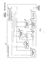
- FIG.1 is a block diagram showing the main configuration of a speech decoding apparatus according to Example 1 of the present invention.
- speech decoding apparatus 100 shown in FIG.1 encoded information transmitted from an encoding apparatus (not shown) is separated into fixed codebook code F n+1 , adaptive codebook code A n+1 , gain code G n+1 , and LPC (Linear Predictive Coefficients) code L n+1 , by demultiplexing section 101.
- frame erasure code B n+1 is input to speech decoding apparatus 100.
- subscript n of each code indicates the number of a frame subject to decoding. That is to say, encoding information in the (n+1)'th frame (hereinafter referred to as "next frame”) after the nth frame subject to decoding (hereinafter referred to as "current frame”) is separated.
- Fixed codebook code F n+1 is input to Fixed Codebook Vector (FCV) decoding section 102, adaptive codebook code A n+1 to Adaptive Codebook Vector (ACV) decoding section 103, gain code G n+1 to gain decoding section 104, and LPC code Ln +1 to LPC decoding section 105.
- Frame erasure code B n+1 is input to FCV decoding section 102, ACV decoding section 103, gain decoding section 104, and LPC decoding section 105.
- FCV decoding section 102 generates a fixed codebook vector using fixed codebook code F n if frame erasure code B n indicates that "the n'th frame is a normal frame", and generates a fixed codebook vector by means of frame erasure concealment processing if frame erasure code B n indicates that "the n'th frame is an erased frame".
- a generated fixed codebook vector is input to gain decoding section 104 and amplifier 106.
- ACV decoding section 103 generates an adaptive codebook vector using adaptive codebook code A n if frame erasure code B n indicates that "the n'th frame is a normal frame", and generates an adaptive codebook vector by means of frame erasure concealment processing if frame erasure code B n indicates that "the n'th frame is an erased frame".
- a generated adaptive codebook vector is input to amplifier 107.
- Gain decoding section 104 generates fixed codebook gain and adaptive codebook gain using gain code G n and a fixed codebook vector if frame erasure code B n indicates that "the n'th frame is a normal frame", and generates fixed codebook gain and adaptive codebook gain by means of frame erasure concealment processing if frame erasure code B n indicates that "the n'th frame is an erased frame”.
- Generated fixed codebook gain is input to amplifier 106, and generated adaptive codebook gain is input to amplifier 107.
- LPC decoding section 105 decodes an LPC parameter using LPC code L n if frame erasure code B n indicates that "the n'th frame is a normal frame", and decodes an LPC parameter by means of frame erasure concealment processing if frame erasure code B n indicates that "the n'th frame is an erased frame”.
- a decoded LPC parameter is input to LPC synthesis section 109. Details of LPC decoding section 105 will be given later herein.
- Amplifier 106 multiplies fixed codebook gain output from gain decoding section 104 by a fixed codebook vector output from FCV decoding section 102, and outputs the multiplication result to adder 108.
- Amplifier 107 multiplies adaptive codebook gain output from gain decoding section 104 by an adaptive codebook vector output from ACV decoding section 103, and outputs the multiplication result to adder 108.
- Adder 108 adds together a fixed codebook vector after fixed codebook gain multiplication output from amplifier 106 and an adaptive codebook vector after adaptive codebook gain multiplication output from amplifier 107, and outputs the addition result (hereinafter referred to as "sum vector") to LPC synthesis section 109.
- LPC synthesis section 109 configures linear predictive synthesis filter using a decoded LPC parameter output from LPC decoding section 105, drives the linear predictive synthesis filter with the sum vector output from adder 108 as an excitation signal, and outputs a synthesized signal obtained as a result of the drive to postfilter 110.
- Postfilter 110 performs formant emphasis and pitch emphasis processing and so forth on the synthesized signal output from LPC synthesis section 109, and outputs the signal as a decoded speech signal.
- FIG.2 is a drawing showing the internal configuration of an LPC decoding section of LPC decoding section 105 in FIG.1 .
- LPC code L n+1 is input to buffer 201 and code vector decoding section 203, and frame erasure code B n+1 is input to buffer 202,code vector decoding section 203, and selector 209.
- Buffer 201 holds next-frame LPC code L n+1 for the duration of one frame, and then outputs this LPC code to code vector decoding section 203.
- the LPC code output from buffer 201 to code vector decoding section 203 is current-frame LPC code L n .
- Buffer 202 holds next-frame frame erasure code B n+1 for the duration of one frame, and then outputs this frame erasure code to code vector decoding section 203.
- the frame erasure code output from buffer 202 to code vector decoding section 203 is current-frame frame erasure code B n .
- Code vector decoding section 203 has quantized prediction residual vectors x n-1 through x n-M of the past M frames, decoded LSF vector y n-1 of one frame before, next-frame LPC code L n+1, next-frame frame erasure code B n+1 , current-frame LPC code L n , and current-frame frame erasure code B n , as input, generates current-frame quantized prediction residual vector x n based on these items of information, and outputs current-frame quantized prediction residual vector x n to buffer 204-1 and amplifier 205-1. Details of code vector decoding section 203 will be given later herein.
- Buffer 204-1 holds current-frame quantized prediction residual vector x n for the duration of one frame, and then outputs this quantized prediction residual vector to code vector decoding section 203, buffer 204-2, and amplifier 205-2.
- the quantized prediction residual vector input to code vector decoding section 203, buffer 204-2, and amplifier 205-2 is quantized prediction residual vector x n-1 of one frame before.
- buffers 204-i (where i is 2 through M-1) each hold quantized prediction residual vector x n-j+1 for the duration of one frame, and then output this quantized prediction residual vector to code vector decoding section 203, buffer 204-(i+1), and amplifier 205-(i+1).
- Buffer 204-M holds quantized prediction residual vector x n-M+1 for the duration of one frame, and then outputs this quantized prediction residual vector to code vector decoding section 203 and amplifier 205-(M+1).
- Amplifier 205-1 multiplies quantized prediction residual vector x n by predetermined MA predictive coefficient ⁇ 0 , and outputs the result to adder 206.
- amplifiers 205-j (where j is 2 through M+1) multiply quantized prediction residual vector x n-j+1 by predetermined MA predictive coefficient ⁇ j-1, and output the result to adder 206.
- the MA predictive coefficient set may be fixed values of one kind, but in ITU-T Recommendation G. 729 two kinds of sets are provided, which set is used for performing decoding is decided on the encoder side, and the set is encoded and transmitted as a part of LPC code L n information. In this case, a configuration is employed whereby LPC decoding section 105 is provided with an MA predictive coefficient set as a table, and a set specified on the encoder side is used as ⁇ 0 through ⁇ M in FIG.2 .
- Adder 206 calculates the sum total of quantized prediction residual vectors after MA predictive coefficient multiplication output from amplifiers 205-1 through 205-(M+1), and outputs the calculation result, decoded LSF vector y n , to buffer 207 and LPC conversion section 208.
- Buffer 207 holds decoded LSF vector y n for the duration of one frame, and then outputs this decoded LSF vector to code vector decoding section 203. As a result, the decoded LSF vector output from buffer 207 to code vector decoding section 203 is decoded LSF vector y n-1 of one frame before.
- LPC conversion section 208 converts decoded LSF vector y n to a set of linear prediction coefficients (decoded LPC parameter), and outputs this to selector 209.
- Selector 209 selects a decoded LPC parameter output from LPC conversion section 208 or a decoded LPC parameter in the preceding frame output from buffer 210 based on current-frame frame erasure code B n and next-frame frame erasure code B n+1 .
- a decoded LPC parameter output from LPC conversion section 208 is selected if current-frame frame erasure code B n indicates that "the n'th frame is a normal frame” or next-frame frame erasure code B n+1 indicates that "the (n+1)'th frame is a normal frame”, and a decoded LPC parameter in the next frame output from buffer 210 is selected if current-frame frame erasure code B n indicates that "the n'th frame is an erased frame” and next-frame frame erasure code B n+1 indicates that "the (n+1)'th frame is an erased frame”. Then selector 209 outputs the selection result to LPC synthesis section 109 and buffer 210 as a final decoded LPC parameter.
- selector 209 selects a decoded LPC parameter in the next frame output from buffer 210, it is not actually necessary to perform all the processing from code vector decoding section 203 through LPC conversion section 208, and only processing to update the contents of buffers 204-1 through 204-M need be performed.
- Buffer 210 holds a decoded LPC parameter output from selector 209 for the duration of one frame, and then outputs this decoded LPC parameter to selector 209.
- the decoded LPC parameter output from buffer 210 to selector 209 is a decoded LPC parameter of one frame before.
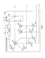
- code vector decoding section 203 in FIG.2 will be described in detail using the block diagram in FIG.3 .
- Codebook 301 generates a code vector identified by current-frame LPC code L n and outputs this to switch 309, and also generates a code vector identified by next-frame LPC code L n+1 and outputs this to amplifier 307.
- ITU-T Recommendation G.729 information that specifies an MA predictive coefficient set is included in LPC code L n , and in this case LPC code L n is also used for MA predictive coefficient decoding in addition to code vector decoding, but a description of this is omitted here.
- a codebook may have a multi-stage configuration and may have a split configuration.
- the codebook configuration is a two-stage configuration with the second stage split into two.
- a vector output from a multi-stage-configuration or split-configuration codebook is generally not used as it is, and if the interval between its elements is extremely small or the order of the elements is reversed, processing is generally performed to guarantee that the minimum interval becomes a specific value or to maintain ordinality.
- Quantized prediction residual vectors x n-1 through x n-M of the past M frames are input to corresponding amplifiers 302-1 through 302-M and corresponding amplifiers 305-1 through 305-M respectively.
- Amplifiers 302-1 through 302-M multiply input quantized prediction residual vectors x n-1 through x n-M by MA predictive coefficients ⁇ 0 through ⁇ M respectively, and output the results to adder 303.
- there are two kinds of MA predictive coefficient sets and information as to which is used is included in LPC code L n .
- the MA predictive coefficient set used in the preceding frame is actually used since LPC code L n has been erased. That is to say, MA predictive coefficient information decoded from preceding-frame LPC code L n-1 is used. If the preceding frame is also an erased frame, information of the frame before that is used.
- Adder 303 calculates the sum total of quantized prediction residual vectors after MA predictive coefficient multiplication output from amplifiers 302-1 through 302-M, and outputs a vector that is the multiplication result to adder 304.
- Adder 304 subtracts the vector output from adder 303 from preceding-frame decoded LSF vector y n-1 output from buffer 207, and outputs a vector that is the result of this calculation to switch 309.
- the vector output from adder 303 is a predictive LSF vector predicted by an MA-type predictor in the current frame, and adder 304 performs processing to find a quantized prediction residual vector in the current frame necessary for a preceding-frame decoded LSF vector to be generated. That is to say, by means of amplifiers 302-1 through 302-M, adder 303, and adder 304, a vector is calculated so that preceding-frame decoded LSF vector y n-1 becomes current-frame decoded LSF vector y n .
- Amplifiers 305-1 through 305-M multiply input quantized prediction residual vectors x n-1 through x n-M by weighting coefficients ⁇ 1 through ⁇ M respectively, and output the results to adder 308.
- Amplifier 306 multiplies preceding-frame decoded LSF vector y n-1 output from buffer 207 by weighting coefficient ⁇ -1 , and outputs the result to adder 308.
- Amplifier 307 multiplies code vector x n+1 output from codebook 301 by weighting coefficient ⁇ 0 , and outputs the result to adder 308.
- Adder 308 calculates the sum total of the vectors output from amplifiers 305-1 through 305-M, amplifier 306, and amplifier 307, and outputs a code vector that is the result of this calculation to switch 309. That is to say, adder 308 calculates a vector by performing weighted addition of a code vector identified by next-frame LPC code L n+1 , the preceding-frame decoded LSF vector, and quantized prediction residual vectors of the past M frames.
- switch 309 selects a code vector output from codebook 301, and outputs this as current-frame quantized prediction residual vector x n .
- switch 309 further selects a vector to be output according to which information next-frame frame erasure code B n+1 has.
- switch 309 selects a vector output from adder 304, and outputs this as current-frame quantized prediction residual vector x n .
- processing for the vector generation process from codebook 301 and amplifiers 305-1 through 305-M to adder 308 need not be performed.
- switch 309 selects a vector output from adder 308, and outputs this as current-frame quantized prediction residual vector x n . In this case, processing for the vector generation process from amplifiers 302-1 through 302-M to adder 304 need not be performed.
- FIG. 4 through FIG.7 presenting actual examples in comparison with conventional technology.
- ⁇ indicates a decoded quantized prediction residue
- ⁇ indicates a decoded quantized prediction residue obtained by concealment processing
- ⁇ indicates a decoded parameter
- ⁇ indicates a decoded parameter obtained by concealment processing.
- FIG. 4 is a drawing showing an example of the result of performing normal processing when there is no erased frame, in which n'th-frame decoded parameter y n is found by means of Equation (1) below from decoded quantized prediction residue.
- c n is an n'th-frame decoded quantized prediction residue.
- y n 0.6 ⁇ c n + 0.3 ⁇ c n - 1 + 0.1 ⁇ c n - 2
- FIG.5 is a drawing showing an example of the result of performing concealment processing of this example
- FIG.6 and FIG.7 are drawings showing examples of the result of performing conventional concealment processing.
- FIG.5 , FIG.6, and FIG.7 it is assumed that the n'th frame is erased and other frames are normal frames.
- quantized prediction residue C n decoded for an erased n' th-frame is found using Equation (3) below so as to make sum D (where D is defined by Equation (2) below) of the distance between (n-1)'th-frame decoded parameter y n-1 and n'th-frame decoded parameter y n and the distance between n'th-frame decoded parameter y n and (n+1)'th-frame decoded parameter y n+1 a minimum, so that fluctuation of the decoded parameter between frames becomes moderate.
- concealment processing of this example finds erased n'th-frame decoded parameter y n by means of Equation (1) above using erased n'th-frame decoded quantized prediction residue C n is found by means of Equation (3).
- decoded parameter y n obtained by means of concealment processing of this example becomes almost the same value as that obtained by normal processing when there is no erased frame.
- decoded parameter y n obtained by means of the conventional concealment processing in FIG.6 has a greatly different value from that obtained by means of normal processing when there is no erased frame. Also, since n'th-frame decoded quantized prediction residue C n is also different, (n+1)'th-frame decoded parameter y n+1 obtained by means of the conventional concealment processing in FIG.6 also has a different value from that obtained by means of normal processing when there is no erased frame.
- the conventional concealment processing shown in FIG.7 finds a decoded quantized prediction residue by means of interpolation, and when the n'th frame is erased, uses the average of (n-1)'th-frame decoded quantized prediction residue C n-1 and (n+1)'th-frame decoded quantized prediction residue C n+1 as n'th-frame decoded quantized prediction residue C n .
- decoded parameter y n obtained by means of the conventional concealment processing in FIG.7 has a greatly different value from that obtained by means of normal processing when there is no erased frame. This is because, whereas a decoded parameter fluctuates moderately between frames through weighted moving averaging, with this conventional concealment processing a decoded parameter also fluctuates together with decoded quantized prediction residue fluctuation.
- (n+1)' th-frame decoded parameter y n+1 obtained by means of the conventional concealment processing in FIG.7 also has a different value from that obtained by means of normal processing when there is no erased frame.
- FIG.8 is a block diagram showing the main configuration of a speech decoding apparatus according to Example 2.
- Speech decoding apparatus 100 shown in FIG.8 differs from that in FIG.1 only in the further addition of concealment mode information E n+1 as a parameter input to LPC decoding section 105.
- FIG.9 is a block diagram showing the internal configuration of LPC decoding section 105 in FIG.8 .
- LPC decoding section 105 shown in FIG.9 differs from that in FIG.2 only in the further addition of concealment mode information E n+1 as a parameter input to code vector decoding section 203.
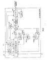
- FIG.10 is a block diagram showing the internal configuration of code vector decoding section 203 in FIG.9 .
- Code vector decoding section 203 shown in FIG.10 differs from that in FIG.3 only in the further addition of coefficient decoding section 401.
- Coefficient decoding section 401 stores a plurality of kinds of sets of weighting coefficients ( ⁇ -1 through ⁇ M ) (hereinafter referred to as "coefficient sets"), selects one weighting coefficient set from among the coefficient sets according to input concealment mode E n+1 , and outputs this to amplifiers 305-1 through 305-M, 306, and 307.
- a plurality of weighted-addition weight ing coefficient sets for performing concealment processing are provided, information for identifying an optimal set is transmitted to the decoder side after confirming for the use of which weighting coefficient set on the encoder side high concealment performance is obtained, and concealment processing is performed using a specified weighting coefficient set based on information received on the decoder side, enabling still higher concealment performance to be obtained than in Example 1.
- FIG.11 is a block diagram showing the main configuration of a speech decoding apparatus according to Example 3.
- Speech decoding apparatus 100 shown in FIG.11 differs from that in FIG.8 only in the further addition of separation section 501 that separates LPC code L n+1 input to LPC decoding section 105 into two kinds of codes, V n+1 and K n+1 .
- Code V is code for generating a code vector
- code K is MA predictive coefficient code.
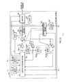
- FIG.12 is a block diagram showing the internal configuration of LPC decoding section 105 in FIG.11 .
- Codes V n and V n+1 that generate a code vector are used in the same way as LPC codes L n and L n+1 , and therefore a description thereof is omitted here.
- LPC decoding section 105 shown in FIG.12 differs from that in FIG.9 only in the further addition of buffer 601 and coefficient decoding section 602, and the further addition of MA predictive coefficient code K n+1 as a parameter input to code vector decoding section 203.
- Buffer 601 holds MA predictive coefficient code K n+1 for the duration of one frame, and then outputs this MA predictive coefficient code to coefficient decoding section 602.
- the MA predictive coefficient code output from buffer 601 to coefficient decoding section 602 is MA predictive coefficient code K n of one frame before.
- Coefficient decoding section 602 stores a plurality of kinds of coefficient sets, identifies a coefficient set by means of frame erasure codes B n and B n+1 , concealment mode E n+1 , and MA predictive coefficient code K n , and outputs this to amplifiers 205-1 through 205-(M+1).
- coefficient set identification can be performed in coefficient decoding section 602, as follows.
- coefficient decoding section 602 selects a coefficient set specified by MA predictive coefficient code K n .
- coefficient decoding section 602 decides a coefficient set to be subject to selection using concealment mode E n+1 received as an (n+1)'th frame parameter. For example, if concealment mode code E n+1 is decided beforehand so as to indicate an MA predictive coefficient mode to be used with an n'th frame that is a concealed frame, concealment mode code E n+1 can be used directly instead of MA predictive coefficient code K n .
- coefficient decoding section 602 repeatedly uses the coefficient set used by the preceding frame.
- provision may be made for a coefficient set of a mode decided beforehand to be used in a fixed manner.
- FIG.13 is a block diagram showing the internal configuration of the code vector decoding section 203 in FIG.12 .
- Code vector decoding section 203 shown in FIG. 13 differs from that in FIG. 10 only in that coefficient decoding section 401 selects a coefficient set using both concealment mode E n+1 and MA predictive coefficient code K n+1 .
- coefficient decoding section 401 is provided with a plurality of weighting coefficient sets, and a weighting coefficient set is prepared according to the MA predictive coefficient used by the next frame.
- MA predictive coefficient sets are of two kinds, with one designated mode 0 and the other mode 1
- MA predictive coefficient sets comprise a group of weighting coefficient sets specifically for use when the next-frame MA predictive coefficient set is mode 0, and a group of weighting coefficient sets specifically for use when the next-frame MA predictive coefficient set is mode 1.
- coefficient decoding section 401 decides a weighting coefficient set group for one or the other of the above, selects one weighting coefficient set from among the coefficient sets according to input concealment mode E n+1 , and outputs this to amplifiers 305-1 through 305-M, 306, and 307.
- quantized prediction residue x n is found by means of Equation (4) below so as to minimize D (j) , the sum of the distance between a decoded parameter in the n'th frame and a decoded parameter in the (n-1)'th frame, and the distance between a decoded parameter in the (n+1)'th frame and a decoded parameter in the n'th frame, so that n'th-frame and (n+1)'th-frame decoded parameters are as far as possible not separated, from an already decoded (n-1)'th-frame decoded parameter.
- Equation (4) When a parameter is an LSF parameter, x n (j) , y n (j) , ⁇ i (j) , and ⁇ ' i (j) in Equation (4) are as follows.
- x n (j) ⁇ 0 j ⁇ x n + 1 j + ⁇ i - 1 M ⁇ i j ⁇ x n - i j + ⁇ - 1 j ⁇ y n - 1 j
- ⁇ i (j) is a weighting coefficient, expressed by ⁇ i (j) and ⁇ ' i (j) . That is to say, if there is only one kind of MA predictive coefficient set, there is also only one kind of weighting coefficient ⁇ i (j) set, but if there are a plurality of kinds of MA predictive coefficient sets, a plurality of kinds of weighting coefficient sets are obtained by combinations of ⁇ i (j) and ⁇ ' i (j) .
- MA predictive coefficient sets are of two kinds, and therefore if these are designated mode 0 and mode 1, it is possible for four kinds of sets to be obtained - when the n'th frame and (n+1)'th frame are both mode 0, when the n'th frame is mode 0 and the (n+1)'th frame is mode 1, when the n'th frame is mode 1 and the (n+1)'th frame is mode 0, and when the n'th frame and (n+1)'th frame are both mode 1.
- a number of methods can be conceived of for deciding which weighting coefficient set is to be used of these four kinds of sets.
- a first method is to generate an n'th-frame decoded LSF and (n+1)'th-frame decoded LSF on the encoder side using all four kinds of sets, calculate the Euclidian distance between the generated n'th-frame decoded LSF and an unquantized LSF obtained by analyzing an input signal, calculate the Euclidian distance between the generated (n+1)'th-frame decoded LSF and an unquantized LSF obtained by analyzing an input signal, choosing one of the weighting coefficient ⁇ sets that minimizes the sum of these Euclidian distances, encoding the chosen set as two bits and transmitting this to the decoder.
- a second method is to make the number of additional bits per frame one by using (n+1)'th-frame MA predictive coefficient mode information. Since (n+1)'th-frame MA predictive coefficient mode information on the decoder side, combinations of ⁇ i (j) and ⁇ ' i (j) are limited to two. That is to say, if the (n+1)'th-frame MA prediction mode is mode 0, an n'th-frame and (n+1)'th-frame MA prediction mode combination is either (0-0) or (1-0), enabling weighting coefficient ⁇ sets to be limited to two kinds.
- a third method is one in which no selection information whatever is sent, a used weighting coefficient set is one for which MA prediction mode combinations are of only two kinds, (0-0) or (1-0), with the former being selected when the (n+1)'th-frame MA predictive coefficient mode is 0, and the latter being selected when the (n+1)'th-frame MA predictive coefficient mode is 1.
- a method may be used whereby an erasure-frame mode is fixed at a specific mode, such as (0-0) or (0-1).
- (n-1)'th-frame and (n+1)'th-frame pitch period information, MA predictive coefficient mode information, or the like can be used to determine stationarity. That is to say, possible methods are to determine that a signal is stationary when a decoded pitch period difference between the (n-1)'th-frame and (n+1)'th-frame is small, or to determine that a signal is stationary when a mode suitable for encoding a frame for which MA predictive coefficient mode information decoded in the (n+1)'th frame is stationary (that is, a mode in which a high-order MA predictive coefficient also has weight of a certain size) has been selected.
- MA predictive coefficient modes are of two kinds, allowing different MA predictive coefficient sets to be used for a stationary section and a section that is not so, and enabling LSF quantizer performance to be improved.
- Equation (5) weighting coefficient set that minimizes Equation (4), decoded LSF parameters of an erased frame and a normal frame that is the next frame after the erased frame are guaranteed not to become values that deviate greatly from an LSF parameter of the frame preceding the erased frame. Consequently, even if a decoded LSF parameter of the next frame is unknown, reception information (a quantized prediction residue) of the next frame can continue to be used effectively, and the risk of concealment being performed in the wrong direction - that is, the risk of deviating greatly from a correct decoded LSF parameter - can be kept to a minimum.
- MA predictive coefficient mode information can be used as part of the information that identifies a weighting coefficient set for concealment processing use, enabling the amount of additionally transmitted weighting coefficient set information for concealment processing use to be reduced.
- FIG.14 is a block diagram showing the internal configuration of gain decoding section 104 in FIG.1 (the same applying to gain decoding section 104 in FIG.8 and FIG. 11 ) .
- gain decoding is performed once on a subframe and one frame is composed of two subframes
- FIG.14 illustrates sequential decoding of gain codes (G m and G m+1 ) of two subframes of the n'th frame, where n denotes a frame number and m denotes a subframe number (the subframe numbers of the first subframe and second subframe of the n'th frame being designated m and m+1 respectively).
- (n+1)'th-frame gain code G n+1 is input to gain decoding section 104 from demultiplexing section 101.
- Gain code G n+1 is input to separation section 700, and is separated into (n+1)'th-frame first-subframe gain code G m+2 and second-subframe gain code G m+3 . Separation into gain codes G m+2 and G m+3 may also be performed by demultiplexing section 101.
- Gain decoding section 104 decodes subframe m decoded gain and subframe m+1 decoded gain in order using G m , G m+1 , G m+2 , and G m+3 generated from input G n and G n+1 .
- Gain code G m+2 is input to buffer 701 and prediction residue decoding section 704, and frame erasure code B n+1 is input to buffer 703, prediction residue decoding section 704, and selector 713.
- Buffer 701 holds an input gain code for the duration of one frame, and then outputs this gain code to prediction residue decoding section 704, so that the gain code input to prediction residue decoding section 704 is the gain code for one frame before. That is to say, if the gain code input to buffer 701 is G m+2 , the output gain code is G m . Buffer 702 also performs the same kind of processing as buffer 701. That is to say, an input gain code is held for the duration of one frame, and then output to prediction residue decoding section 704. The only difference is that buffer 701 input/output is first-subframe gain code, and buffer 702 input/output is second-subframe gain code.
- Buffer 703 holds next-frame frame erasure code B n+1 for the duration of one frame, and then outputs this frame erasure code to prediction residue decoding section 704, selector 713, and FC vector energy calculation section 708.
- the frame erasure code output from buffer 703 to prediction residue decoding section 704, selector 713, and FC vector energy calculation section 708 is the frame erasure code of one frame before the input frame, and is thus current-frame frame erasure code B n .
- Prediction residue decoding section 704 has logarithmic quantized prediction residues (resulting from finding the logarithms of quantized MA prediction residues) x m-1 through x m-M of the past M subframes, decoded energy (logarithmic decoded gain) e m-1 of one subframe before, prediction residue bias gain e B , next-frame gain codes G m+2 and G m+3 , next-frame frame erasure code B n+1 , current-frame gain codes G m and G m+1 , and current-frame frame erasure code B n , as input, generates a current-frame quantized prediction residue based on these items of information, and outputs this to logarithm calculation section 705 and multiplication section 712. Details of prediction residue decoding section 704 will be given later herein.
- Logarithm calculation section 705 calculates logarithm x m of a quantized prediction residue output from prediction residue decoding section 704 (in ITU-T Recommendation G. 729, 20 ⁇ log 10 (x), where x is input), and outputs this to buffer 706-1.
- Buffer 706-1 has logarithmic quantized prediction residue x m output from logarithm calculation section 705 as input, holds this for the duration of one subframe, and then outputs this logarithmic quantized prediction residue to prediction residue decoding section 704, buffer 706-2 and buffer 707-1. That is to say, the logarithmic quantized prediction residue input to prediction residue decoding section 704, buffer 706-2, and amplifier 707-1 is logarithmic quantized prediction residue x m-1 of one subframe before.
- buffers 706-i (where i is 2 through M-1) each hold input logarithmic quantized prediction residue x m-i for the duration of one subframe, and then output this logarithmic quantized prediction residue to prediction residue decoding section 704, buffer 706-(i+1), and amplifier 707-i.
- Buffer 706-M holds input logarithmic quantized prediction residue x m-M-1 for the duration of one subframe, and then outputs this logarithmic quantized prediction residue to prediction residue decoding section 704 and amplifier 707-M.
- Amplifier 707-1 multiplies logarithmic quantized prediction residue x m-i by predetermined MA predictive coefficient ⁇ 1 , and outputs the result to adder 710.
- amplifiers 707-j (where j is 2 through M) each multiply logarithmic quantized prediction residue x m-j by predetermined MA predictive coefficient ⁇ j , and output the result to adder 710.
- the MA predictive coefficient set comprises fixed values of one kind in ITU-T Recommendation G.729, but a configuration may also be used whereby a plurality of kinds of sets are provided and a suitable one is selected.
- FC vector energy calculation section 708 calculates the energy of an FC (fixed codebook) vector decoded separately, and outputs the calculation result to average energy addition section 709. If current-frame frame erasure code B n indicates that "the n'th frame is an erased frame", FC vector energy calculation section 708 outputs the FC vector energy of the preceding subframe to average energy addition section 709.
- Average energy addition section 709 subtracts the FC vector energy output from FC vector energy calculation section 708 from the average energy, and outputs the subtraction result, prediction residue bias gain e B , to prediction residue decoding section 704 and adder 710.
- average energy is assumed to be a preset constant. Also, energy addition/subtraction is performed in the logarithmic domain.
- Adder 710 calculates the sum total of logarithmic quantized prediction residues after MA predictive coefficient multiplication output from amplifiers 707-1 through 707-M and prediction residue bias gain e B output from average energy addition section 709, and outputs logarithmic prediction gain that is the result of this calculation to exponential calculation section 711.
- Exponential calculation section 711 calculates an exponential (10 x , where x is input) of logarithmic prediction gain output from adder 710, and outputs prediction gain that is the result of this calculation to multiplier 712.
- Multiplier 712 multiplies the prediction gain output from exponential calculation section 711 by the quantized prediction residue output from prediction residue decoding section 704, and outputs decoded gain that is the result of this calculation to selector 713.
- Selector 713 selects either decoded gain output from multiplier 712 or post-attenuation preceding-frame decoded gain output from amplifier 715 based on current-frame frame erasure code B n and next-frame frame erasure code B n+1 .
- decoded gain output from multiplier 712 is selected if current-frame frame erasure code B n indicates that "the n'th frame is a normal frame” or next-frame frame erasure code B n+1 indicates that "the (n+1)'th frame is a normal frame”, and post-attenuation preceding-frame decoded gain output from amplifier 715 is selected if current-frame frame erasure code B n indicates that "the n'th frame is an erased frame” and next-frame frame erasure code B n+1 indicates that "the (n+1)'th frame is an erased frame”. Then selector 713 outputs the selection result as final prediction gain to amplifiers 106 and 107, buffer 714, and logarithm calculation section 716.
- selector 713 selects post-attenuation preceding-frame decoded gain output from amplifier 715, it is not actually necessary to perform all the processing from prediction residue decoding section 704 through multiplier 712, and only processing to update the contents of buffers 706-1 through 706-M need be performed.
- Buffer 714 holds decoded gain output from selector 713 for the duration of one subframe, and then outputs this decoded gain to amplifier 715.
- the decoded gain output from buffer 714 to amplifier 715 is the decoded gain of one subframe before.
- Amplifier 715 multiplies the decoded gain of one subframe before output from buffer 714 by a predetermined attenuation coefficient, and outputs the result to selector 713.
- this predetermined attenuation coefficient is 0.98 in ITU-T Recommendation G.729, for example, but an optimal value for the codec may be set as appropriate, and the value may also be changed according to the characteristics of an erased frame signal, such as whether the erased frame is a voiced frame or an unvoiced frame.
- Logarithm calculation section 716 calculates logarithm e m of decoded gain output from selector 713 (in ITU-T Recommendation G. 729, 20 ⁇ log 10 (x), where x is input), and outputs this to buffer 717.
- Buffer 717 has logarithmic decoded gain e m as input from logarithm calculation section 716, holds this for the duration of one subframe, and then outputs this logarithmic decoded gain to prediction residue decoding section 704. That is to say, the logarithmic prediction gain input to prediction residue decoding section 704 is logarithmic decoded gain e m-1 of one subframe before.
- FIG.15 is a block diagram showing the internal configuration of prediction residue decoding section 704 in FIG.14 .
- gain codes G m , G m+1 , G m+2 , and G m+3 are input to codebook 801
- frame erasure codes B n and B n+1 are input to switch 812
- logarithmic quantized prediction residues x m-1 through x m-M of the past M subframes are input to adder 802
- logarithmic decoded gain e m-1 of one subframe before and prediction residue bias gain e B are inputtosubframequantized prediction residue generation section 807 and subframe quantized prediction residue generation section 808.
- Codebook 801 decodes corresponding quantized prediction residues from input gain codes G m , G m+1 , G m+2 , and G m+3 , outputs quantized prediction residues corresponding to input gain codes G m and G m+1 to switch 812 via switch 813, and outputs quantized prediction residues corresponding to input gain codes G m+2 and G m+3 to logarithm calculation section 806.
- Switch 813 selects either of quantized prediction residues decoded from gain codes G m and G m+1 , and outputs this to switch 812. Specifically, a quantized prediction residue decoded from gain code G m is selected when first-subframe gain decoding processing is performed, and a quantized prediction residue decoded from gain code G m+1 is selected when second-subframe gain decoding processing is performed.
- Adder 802 calculates the sum total of logarithmic quantized prediction residues x m-1 through x m-M of the past M subframes, and outputs the result of this calculation to amplifier 803.
- Amplifier 803 calculates an average by multiplying the adder 802 output value by 1/M, and outputs the result of this calculation to 4dB attenuation section 804.
- 4 dB attenuation section 804 lowers the amplifier 803 output value by 4 dB, and outputs the result to exponential calculation section 805.
- This 4 dB attenuation is to prevent a predictor outputting an excessively large prediction value in a frame (subframe) recovered from frame erasure, and an attenuator is not necessarily essential in a configuration example in which such a necessity does not arise.
- the 4 dB attenuation amount also, it is possible to design an optimal value freely.
- Exponential calculation section 805 calculates an exponential of the 4dB attenuation section 804 output value, and outputs a concealed prediction residue that is the result of this calculation to switch 812.
- Logarithm calculation section 806 calculates logarithms of two quantized prediction residues output from codebook 801 (resulting from decoded gain codes G m+2 and G m+3 ), and outputs logarithmic quantized prediction residues x m+2 and x m+3 that are the results of the calculations to subframe quantized prediction residue generation section 807 and subframe quantized prediction residue generation section 808.
- Subframequantized predictionresiduegeneration section 807 has logarithmic quantized prediction residues x m+2 and x m+3 , logarithmic quantized prediction residues x m-1 through x m-M of the past M subframes, decoded energy e m-1 of one subframe before, and prediction residue bias gain e B , as input, calculates a first-subframe logarithmic quantized prediction residue based on these items of information, and outputs this to switch 810.
- subframe quantized prediction residue generation section 808 has logarithmic quantized prediction residues x m+2 and x m+3 , logarithmic quantized prediction residues x m-1 through x m-M of the past M subframes, decoded energy e m-1 of one subframe before, and prediction residue bias gain e B , as input, calculates a second-subframe logarithmic quantized prediction residue based on these items of information, and outputs this to buffer 809. Details of subframe quantized prediction residue generation sections 807 and 808 will be given later herein.
- Buffer 809 holds the second-subframe logarithmic quantized prediction residue output from subframe quantized prediction residue generation section 808 for the duration of one subframe, and outputs this second-subframe logarithmic quantized prediction residue to switch 810 when second-subframe processing is performed.
- x m-1 through x m-M , e m-1 , and e B are updated outside prediction residue decoding section 704, but no processing is performed by either subframe quantized prediction residue generation section 807 or subframe quantized prediction residue generation section 808, and all processing is performed at the time of first-subframe processing.
- switch 810 is connected to subframe quantized prediction residue generation section 807, and outputs a generated first-subframe logarithmic quantized prediction residue to exponential calculation section 811, whereas at the time of second-subframe processing, switch 810 is connected to buffer 809, and outputs a second-subframe logarithmic quantized prediction residue generated by subframe quantized prediction residue generation section 808 to exponential calculation section 811.
- Exponential calculation section 811 exponentiates a logarithmic quantized residue output from switch 810, and outputs a concealed prediction residue that is the result of this calculation to switch 812.
- switch 812 selects a quantized prediction residue output from codebook 801 via switch 813. On the other hand, if current-frame frame erasure code B n indicates that "the n'th frame is an erased frame", switch 812 further selects a quantized prediction residue to be output according to which information next-frame frame erasure code B n+1 has.
- switch 812 selects a concealed prediction residue output from exponential calculation section 805 if next-frame frame erasure code B n+1 indicates that "the (n+1)'th frame is an erased frame”, and selects a concealed prediction residue output from exponential calculation section 811 if next-frame frame erasure code B n+1 indicates that "the (n+1)'th frame is a normal frame”.
- Data input to a terminal other than the selected terminal is not necessary, and therefore, in actual processing, it is usual first to decide which terminal is to be selected in switch 812, and to perform processing to generate a signal to be output to the decided terminal.
- FIG.16 is a block diagram showing the internal configuration of subframe quantized prediction residue generation section 807 in FIG.15 .
- the internal configuration of subframe quantized prediction residue generation section 808 is also identical to that in FIG. 16 , and only the weighting coefficient values differ from thoseinsubframequantized prediction residue generation section 807.
- Amplifiers 901-1 through 901-M multiply input logarithmic quantized prediction residues x m-1 through x m-M by weighting coefficients ⁇ 1 through ⁇ M respectively, and output the results to adder 906.
- Amplifier 902 multiplies preceding-subframe logarithmic gain e m-1 by weighting coefficient ⁇ -1 , and outputs the result to adder 906.
- Amplifier 903 multiplies logarithmic bias gain e B by weighting coefficient ⁇ B , and outputs the result to adder 906.
- Amplifier 904 multiplies logarithmic quantized prediction residue x m+2 by weighting coefficient ⁇ 00 , and outputs the result to adder 906.
- Amplifier 905 multiplies logarithmic quantized prediction residue x m+3 by weighting coefficient ⁇ 01 , and outputs the result to adder 906.
- Adder 906 calculates the sum total of the logarithmic quantized prediction residues output from amplifiers 901-1 through 901-M, amplifier 902, amplifier 903, amplifier 904,and amplifier 905, and outputs the result of this calculation to switch 810.
- Equation (6) y m-1 , y m , y m+1 , y m+2 , y m+3 , x m , x m+1 , x m+2 , x m+3 , x B , and ⁇ i are as follows.
- Equation (7) and Equation (8) are obtained.
- ⁇ 00 , ⁇ 01 , ⁇ 1 through ⁇ M , ⁇ -1 , ⁇ B , ⁇ ' 00 , ⁇ ' 01 , ⁇ ' 1 through ⁇ ' M , ⁇ ' -1 , and ⁇ ' B are found from ⁇ 0 through ⁇ M , they are decided uniquely.
- current-frame logarithmic quantized prediction residue concealment processing is performed by means of weighted addition processing specifically for concealment processing using a logarithmic quantized prediction residue received in the past and a next-frame logarithmic quantized prediction residue, and gain parameter decoding is performed using a concealed logarithmic quantized prediction residue, enabling higher concealment performance to be achieved than when a past decoded gain parameter is used after monotonic decay.
- Equation (6) decoded logarithmic gain parameters of an erased frame (two subframes) and a normal frame (two subframes) that is the next frame (two subframes) after the erased frame are guaranteed not to be greatly separated from a logarithmic gain parameter of the frame preceding the erased frame.
- reception information a logarithmic quantized prediction residue of the next frame (two subframes) can continue to be used effectively, and the risk of concealment being performed in the wrong direction (the risk of deviating greatly from a correct decoded gain parameter) can be kept to a minimum.
- FIG.17 is a block diagram showing the main configuration of a speech encoding apparatus according to Example 5.
- FIG.17 shows an example of encoding of concealment mode information E n+1 to decide a weighting coefficient set by means of the second method described in Example 3 - that is, a method whereby (n-1)'th-frame concealment mode information is represented by one bit using n'th-frame MA predictive coefficient mode information.
- preceding-frame LPC concealment section 1003 finds an (n-1)'th-frame concealment LSF as described using FIG.13 by means of the weighted sum of the current-frame decoded quantized prediction residue and the decoded quantized prediction residues of two frames before through M+1 frames before.
- an n'th-frame concealment LSF was found using (n+1)'th-frame encoding information
- an (n-1)'th-frame concealment LSF is found using n'th-frame encoding information, and therefore the correspondence relationship is one of displacement by one frame number.
- Concealment mode determiner 1004 performs a mode decision based on which of ⁇ 0 n (j) and ⁇ 1 n (j) is closer to input LSF ⁇ n (j) .
- the degree of separation of ⁇ 0 n (j) and ⁇ 1 n (j) from ⁇ n (j) may be based on simple Euclidian distance, or may be based on a weighted Euclidian distance such as used in ITU-T Recommendation G.729 LSF quantization.
- Input signal s n is input to LPC analysis section 1001, target vector calculation section 1006, and filter state update section 1013.
- LPC encoding section 1002 performs quantization and encoding of the input LPC (linear predictive coefficients), and outputs quantized linear predictive coefficients a' j to impulse response calculation section 1005, target vector calculation section 1006, and synthesis filter section 1011.
- LPC quantization and encoding are performed in the LSF parameter domain.
- LPC encoding section 1002 outputs LPC encoding result L n to multiplexing section 1014, and outputs quantized prediction residue x n , decoded quantized LSF parameter ⁇ ' n (j) , and MA predictive quantization mode K n to preceding-frame LPC concealment section 1003.
- Preceding-frame LPC concealment section 1003 holds n'th-frame decoded quantized LSF parameter ⁇ ' n (j) output from LPC encoding section 1002 in a buffer for the duration of two frames.
- the decoded quantized LSF parameter of two frames before is ⁇ ' n-2 (j) .
- preceding-frame LPC concealment section 1003 holds n'th-frame decoded quantized prediction residue x n for the duration of M+1 frames.
- preceding-frame LPC concealment section 1003 generates (n-1) 'th-frame decoded quantized LSF parameters ⁇ 0 n (j) and ⁇ 1 n (j) by means of the weighted sum of quantized prediction residue x n , decoded quantized LSF parameter ⁇ ' n-2 (j) of two frames before, and decoded quantized prediction residues x n-2 through x n-M-1 of two frames before through M+1 frames before, and outputs the result to concealment mode determiner 1004.
- preceding-frame LPC concealment section 1003 is provided with four kinds of weighting coefficient sets when finding a weighted sum, but two of the four kinds are chosen according to whether MA predictive quantization mode information K n input from LPC encoding section 1002 is 0 or 1, and are used for ⁇ 0 n (j) and ⁇ 1 n (j) generation.
- Concealment mode determiner 1004 determines which of the two kinds of concealment LSF parameters ⁇ 0 n (j) and ⁇ 1 n (j) output from preceding-frame LPC concealment section 1003 is closer to unquantized LSF parameter ⁇ n (j) output from LPC analysis section 1001, and outputs code E n corresponding to a weighting coefficient set that generates the closer concealed LSF parameter to multiplexing section 1014.
- Impulse response calculation section 1005 generates perceptual weighting synthesis filter impulse response h using unquantized linear predictive coefficients a j output from LPC analysis section 1001 and quantized linear predictive coefficients a' j output from LPC encoding section 1002, and outputs these to ACV encoding section 1007 and FCV encoding section 1008.
- Target vector calculation section 1006 calculates target vector o (a signal in which a perceptual weighting synthesis filter zero input response has been subtracted from a signal resulting from applying a perceptual weighting filter to an input signal) from input signal s n , unquantized linear predictive coefficients a j output from LPC analysis section 1001, and quantized linear predictive coefficients a' j output from LPC encoding section 1002, and outputs these to ACV encoding section 1007, gain encoding section 1009, and filter state update section 1012.
- target vector o a signal in which a perceptual weighting synthesis filter zero input response has been subtracted from a signal resulting from applying a perceptual weighting filter to an input signal
- ACV encoding section 1007 has target vector o from target vector calculation section 1006, perceptual weighting synthesis filter impulse response h from impulse response calculation section 1005, and excitation signal ex from excitation generation section 1010, as input, performs an adaptive codebook search, and outputs resulting adaptive codebook code
- a more concrete search method is similar to that described in ITU-T Recommendation G.729 and so forth. Although omitted in FIG.17 , it is usual for the amount of computation necessary for an adaptive codebook search to be kept down by deciding a range in which a closed-loop pitch search is performed by means of an open-loop pitch search or the like.
- FCV encoding section 1008 has fixed codebook target vector o' and quantized pitch lag T as input from ACV encoding section 1007, and perceptual weighting synthesis filter impulse response h as input from impulse response calculation section 1005, performs a fixed codebook search by means of a method such as described in ITU-T Recommendation G.729, for example, and outputs fixed codebook code F n to multiplexing section 1014, FC vector u to excitation generation section 1010, and filtered FC contribution q obtained by performing convolution of a perceptual weighting synthesis filter impulse response on FC vector u to filter state update section 1012 and gain encoding section 1009.
- Gain encoding section 1009 has target vector o as input from target vector calculation section 1006, filtered AC vector contribution p as input from ACV encoding section 1007, and filtered FC vector contribution q as input from FCV encoding section 1008, and outputs a pair of ga and gf for which
- Excitation generation section 1010 has adaptive codebook vector v as input fromACV encoding section 1007, fixed codebook vector u as input from FCV encoding section 1008, adaptive codebook vector gain ga and fixed codebook vector gain gf as input from gain encoding section 1009, calculates excitation vector ex as gaxv+gfxu, and outputs this to ACV encoding section 1007 and synthesis filter section 1011. Excitation vector ex output to ACV encoding section 1007 is used for updating ACB (past generated excitation vector buffer) in the ACV encoding section.
- ACB past generated excitation vector buffer
- Synthesis filter section 1011 drives a linear predictive filter configured by means of quantized linear predictive coefficients a' j output from LPC encoding section 1002 by means of excitation vector ex output from excitation generation section 1010, generates local decoded speech signal s' n , and outputs this to filter state update section 1013.
- Filter state update section 1012 has synthesis adaptive codebook vector p as input from ACV encoding section 1007, synthesis fixed codebook vector q as input from FCV encoding section 1008, and target vector o as input from target vector calculation section 1006, generates a filter state of a perceptual weighting filter in target vector calculation section 1006, and outputs this to target vector calculation section 1006.
- Filter state updating section 1013 calculates error between local decoded speech signal s' n input from synthesis filter section 1011 and input signal s n , and outputs this to target vector calculation section 1006 as the state of the synthesis filter in target vector calculation section 1006.
- Multiplexing section 1014 outputs encoding information in which codes F n , An, G n , L n , and E n are multiplexed.
- an example has been shown in which error with respect to an unquantized LSF parameter is calculated only for an (n-1)'th-frame decoded quantized LSF parameter, but provision may also be made for a concealment mode to be decided taking error between an n'th-frame decoded quantized LSF parameter and n'th- frame unquanti zed LSF parameter into consideration.
- an optimal concealment processing weighting coefficient set is identified for concealment processing for a speech decoding apparatus of Example 3, and that information is transmitted to the decoder side, enabling higher concealment performance to be obtained and decoded speech signal quality to be improved on the decoder side.
- FIG.18 is a block diagram showing the configuration of a speech signal transmitting apparatus and speech signal receiving apparatus configuring a speech signal transmission system according to Example.
- the only difference from conventional system is that a speech encoding apparatus of Example 5 is applied to a speech signal transmitting apparatus, and a speech decoding apparatus of any of Examples 1 through 3 is applied to a speech signal receiving apparatus.
- Speech signal transmitting apparatus 1100 has input apparatus 1101, A/D conversion apparatus 1102, speech encoding apparatus 1103, signal processing apparatus 1104, RF modulation apparatus 1105, transmitting apparatus 1106, and antenna 1107.
- An input terminal of A/D conversion apparatus 1102 is connected to input apparatus 1101.
- An input terminal of speech encoding apparatus 1103 is connected to an output terminal of A/D conversion apparatus 1102.
- An input terminal of signal processing apparatus 1104 is connected to an output terminal of speech encoding apparatus 1103.
- An input terminal of RF modulation apparatus 1105 is connected to an output terminal of signal processing apparatus 1104.
- An input terminal of transmitting apparatus 1106 is connected to an output terminal of RF modulation apparatus 1105.
- Antenna 1107 is connected to an output terminal of transmitting apparatus 1106.
- Input apparatus 1101 receives a speech signal, converts this to an analog speech signal that is an electrical signal, and provides this signal to A/D conversion apparatus 1102.
- A/D conversion apparatus 1102 converts the analog speech signal from input apparatus 1101 to a digital speech signal, and provides this signal to speech encoding apparatus 1103.
- Speech encoding apparatus 1103 encodes the digital speech signal from A/D conversion apparatus 1102 and generates a speech encoded bit stream, and provides this bit stream to signal processing apparatus 1104.
- Signal processing apparatus 1104 performs channel encoding processing, packetization processing, transmission buffer processing, and so forth on the speech encoded bit stream from speech encoding apparatus 1103, and then provides that speech encoded bit stream to RF modulation apparatus 1105.
- RF modulation apparatus 1105 modulates the speech encoded bit stream signal from signal processing apparatus 1104 on which channel encoding processing and so forth has been performed, and provides the signal to transmitting apparatus 1106. Transmitting apparatus 1106 transmits the modulated speech encoded bit stream from RF modulation apparatus 1105 as a radio wave (RF signal) via antenna 1107.
- RF signal radio wave
- speech signal transmitting apparatus 1100 processing is performed on a digital speech signal obtained via A/D conversion apparatus 1102 in frame units of several tens of ms. If a network configuring a system is a packet network, one frame or several frames of encoded data are put into one packet, and this packet is transmitted to the packet network. If the network is a circuit switched network, packetization processing and transmission buffer processing are unnecessary.
- Speech signal receiving apparatus 1150 has antenna 1151, receiving apparatus 1152, RF demodulation apparatus 1153, signal processing apparatus 1154, speech decoding apparatus 1155, D/A conversion apparatus 1156, and output apparatus 1157.
- An input terminal of receiving apparatus 1152 is connected to antenna 1151.
- An input terminal of RF demodulation apparatus 1153 is connected to an output terminal of receiving apparatus 1152.
- Two input terminals of signal processing apparatus 1154 are connected to two output terminals of RF demodulation apparatus 1153.
- Two input terminals of speech decoding apparatus 1155 are connected to two output terminals of signal processing apparatus 1154.
- An input terminal of D/A conversion apparatus 1156 is connected to an output terminal of speech decoding apparatus 1155.
- An input terminal of output apparatus 1157 is connected to an output terminal of D/A conversion apparatus 1156.
- Receiving apparatus 1152 receives a radio wave (RF signal) including speech encoded information via antenna 1151 and generates a received speech encoded signal that is an analog electrical signal, and provides this signal to RF demodulation apparatus 1153. If there is no signal attenuation or noise superimposition in the transmission path, the radio wave (RF signal) received via the antenna is exactly the same as the radio wave (RF signal) transmitted by the speech signal transmitting apparatus.
- RF signal radio wave
- RF demodulation apparatus 1153 demodulates the received speech encoded signal from receiving apparatus 1152, and provides this signal to signal processing apparatus 1154.
- RF demodulation apparatus 1153 also separately provides signal processing apparatus 1154 with information as to whether or not the received speech encoded signal has been able to be demodulated normally.
- Signal processing apparatus 1154 performs jitter absorption buffering processing, packet assembly processing, channel decoding processing, and so forth on the received speech encoded signal from RF demodulation apparatus 1153, and provides a received speech encoded bit stream to speech decoding apparatus 1155.
- RF demodulation apparatus 1153 information as to whether or not the received speech encoded signal has been able to be demodulated normally is input from RF demodulation apparatus 1153, and if the information input from RF demodulation apparatus 1153 indicates that "demodulation has not been able to be performed normally", or if packet assembly processing or the like in the signal processing apparatus has not been able to be performed normally and the received speech encoded bit stream has not been able to be decoded normally, the occurrence of frame erasure is conveyed to speech decoding apparatus 1155 as frame erasure information.
- Speech decoding apparatus 1155 performs decoding processing on the received speech encoded bit stream from signal processing apparatus 1154 and generates a decoded speech signal, and provides this signal to D/A conversion apparatus 1156.
- Speech decoding apparatus 1155 decides whether to perform normal decoding processing or to perform decoding processing by means of frame erasure concealment processing in accordance with frame erasure information input in parallel with the received speech encoded bit string.
- D/A conversion apparatus 1156 converts the digital decoded speech signal from speech decoding apparatus 1155 to an analog decoded speech signal, and provides this signal to output apparatus 1157.
- Output apparatus 1157 converts the analog decoded speech signal from D/A conversion apparatus 1156 to vibrations of the air, and outputs these as a sound wave audible to the human ear.
- a decoded speech signal of better quality than heretofore can be obtained even if a transmission path error (in particular, a frame erasure error typified by a packet loss) occurs.
- a transmission path error in particular, a frame erasure error typified by a packet loss
- Example 7 a case will be described in which an AR type is used as a prediction model.
- the configuration of a speech decoding apparatus according to Example 7 is identical to that in FIG.1 .
- FIG.19 is a drawing showing the internal configuration of LPC decoding section 105 of a speech decoding apparatus according to this example. Configuration parts in FIG. 19 common to FIG. 2 are assigned the same reference codes as in FIG.2 , and detailed descriptions thereof are omitted here.
- LPC decoding section 105 shown in FIG.19 employs a configuration in which, in comparison with FIG.2 , parts relating to prediction (buffers 204, amplifiers 205, and adder 206) and parts relating to frame erasure concealment (code vector decoding section 203 and buffer 207) have been eliminated, and configuration parts replacing these (code vector decoding section 1901, amplifier 1902, adder 1903, and buffer 1904) have been added.
- LPC code L n+1 is input to buffer 201 and code vector decoding section 1901, and frame erasure code B n+1 is input to buffer 202, code vector decoding section 1901, and selector 209.
- Buffer 201 holds next-frame LPC code L n+1 for the duration of one frame, and then outputs this LPC code to code vector decoding section 1901.
- the LPC code output from buffer 201 to code vector decoding section 1901 is current-frame LPC code L n .
- Buffer 202 holds next-frame frame erasure code B n+1 for the duration of one frame, and then outputs this frame erasure code to code vector decoding section 1901.
- the frame erasure code output from buffer 202 to code vector decoding section 1901 is current-frame frame erasure code B n .
- Code vector decoding section 1901 has decoded LSF vector y n-1 of one frame before, next-frame LPC code L n+1 , next- f rame frame erasure code B n+1 , current- f rame LPC code L n , and current-frame frame erasure code B n , as input, generates current-frame quantized prediction residual vector x n based on these items of information, and outputs current-frame quantized prediction residual vector x n to adder 1903. Details of code vector decoding section 1901 will be given later herein.
- Amplifier 1902 multiplies next-frame decoded LSF vector y n-1 by predetermined AR predictive coefficient ⁇ 1 , and outputs the result to adder 1903.
- Adder 1903 calculates the sum the predictive LSF vector output from amplifier 1902 (that is, the result of multiplying the preceding-frame decoded LSF vector by an AR predictive coefficient) and current-frame quantized prediction residual vector x n , and outputs the multiplication result, decoded LSF vector y n , to buffer 1904 and LPC conversion section 208.
- Buffer 1904 holds decoded LSF vector y n for the duration of one frame, and then outputs this decoded LSF vector to code vector decoding section 1901 and amplifier 1902. As a result of being held in buffer 1904 for the duration of one frame, the decoded LSF vector input to code vector decoding section 1901 and amplifier 1902 is decoded LSF vector y n-1 of one frame before.
- selector 209 selects a decoded LPC parameter in the preceding frame output from buffer 210, it is not actually necessary to perform all the processing from code vector decoding section 1901 through LPC conversion section 208.
- code vector decoding section 1901 in FIG. 19 will be described in detail using the block diagram in FIG.20 .
- Codebook 2001 generates a code vector identified by current-frame LPC code L n and outputs this to switch 309, and also generates a code vector identified by next-frame LPC code L n+1 and outputs this to amplifier 2002. Also, a codebook may have a multi-stage configuration and may have a split configuration.
- Amplifier 2002 multiplies code vector xn+1 output from codebook 2001 by weighting coefficient b 0 , and outputs the result to adder 2005.
- Amplifier 2003 performs processing to find a quantized prediction residual vector in the current frame necessary for a preceding-frame decoded LSF vector to be generated. That is to say, amplifier 2003 calculates current-frame vector x n so that preceding-frame decoded LSF vector y n-1 becomes current-frame decoded LSF vector y n . Specifically, amplifier 2003 multiplies input preceding-frame decoded LSF vector y n-1 by coefficient (1-a 1 ). Then amplifier 2003 outputs the result of this calculation to switch 309.
- Amplifier 2004 multiplies input preceding-frame decoded LSF vector y n-1 by weighting coefficient b -1 , and outputs the result to adder 2005.
- Adder 2005 calculates the sum of the vectors output from amplifier 2002 and amplifier 2004, and outputs a code vector that is the result of this calculation to switch 309. That is to say, adder 2005 calculates current-frame vector x n by performing weighted addition of a code vector identified by next-frame LPC code L n+1 and the preceding-frame decoded LSF vector.
- switch 309 selects a code vector output from codebook 2001, and outputs this as current-frame quantized prediction residual vector x n .
- switch 309 further selects a vector to be output according to which information next-frame frame erasure code B n+1 has.
- switch 309 selects a vector output from coding apparatus 2003, and outputs this as current-frame quantized prediction residual vector x n .
- processing for the vector generation process from codebook 2001 and amplifiers 2002 and 2004 through adder 2005 need not be performed.
- y n-1 may be used as y n
- x n need not necessarily be generated by amplifier 2003 processing.
- switch 309 selects a vector output from adder 2005, and outputs this as current-frame quantized prediction residual vector x n . In this case, amplifier 2003 processing need not be performed.
- weighting coefficients b -1 and b 0 are decided so that sum D (where D is as shown in Equation (9) below) of the distance between (n-1)'th-frame decoded parameter y n-1 and n'th-frame decoded parameter y n and the distance between n'th-frame decoded parameter y n and (n+1)'th-frame decoded parameter y n+1 becomes small, so that fluctuation between decoded parameter frames becomes moderate.
- Equation (10) is solved for decoded quantized prediction residual vector x n of an erased n'th frame.
- x n can be found by means of Equation (11) below.
- Equation (12) is replaced by Equation (12).
- a1 represents an AR predictive coefficient
- a 1 (j) represents the j'th element of an AR predictive coefficient set (that is, a coefficient multiplied by y n-1 (j) , the j'th element of preceding-frame decoded LSF parameter y n-1 ).
- Example 7 a case has been described in which there is only one kind of predictive coefficient set, but the present technique is not limited to this and can also be applied to a case in which there are a plurality of kinds of predictive coefficient sets, in the same way as in Examples 2 and 3.
- Example 8 an example of a case will be described in which an AR type for which there are a plurality of kinds of predictive coefficient sets is used.
- FIG.21 is a block diagram of a speech decoding apparatus according to this example. Except for a difference in the internal configuration of the LPC decoding section and the absence of a concealment mode information E n+1 input line from demultiplexing section 101 to LPC decoding section 105, the configuration of speech decoding apparatus 100 shown in FIG. 21 is identical to that in FIG.11 .
- FIG.22 is a drawing showing the internal configuration of LPC decoding section 105 of a speech decoding apparatus according to this example. Configuration parts in FIG.22 common to FIG.19 are assigned the same reference codes as in FIG.19 , and detailed descriptions thereof are omitted here.
- LPC decoding section 105 shown in FIG.22 employs a configuration in which, in comparison with FIG.19 , buffer 2202 and coefficient decoding section 2203 have been added. Also, the operation and internal configuration of code vector decoding section 2201 in FIG.22 differ from those of code vector decoding section 1901 in FIG.19 .
- LPC code V n+1 is input to buffer 201 and code vector decoding section 2201, and frame erasure code B n+1 is input to buffer 202, code vector decoding section 2201, and selector 209.
- Buffer 201 holds next-frame LPC code V n+1 for the duration of one frame, and then outputs this LPC code to code vector decoding section 2201.
- the LPC code output from buffer 201 to code vector decoding section 2201 is current-frame LPC code V n .
- buffer 202 holds next-frame frame erasure code B n+1 for the duration of one frame, and then outputs this frame erasure code to code vector decoding section 2201.
- Code vector decoding section 2201 has decoded LSF vector y n-1 of one frame before, next-frame LPC code V n+1 , next-frame frame erasure code B n+1 , current-frame LPC code V n , next-frame predictive coefficient code K n+1 , and current-frame frame erasure code B n , as input, generates current-frame quantized prediction residual vector x n based on these items of information, and outputs current-frame quantized prediction residual vector x n to adder 1903. Details of code vector decoding section 2201 will be given later herein.
- Buffer 2202 holds AR predictive coefficient code K n+1 for the duration of one frame, and then outputs this AR predictive coefficient code to coefficient decoding section 2203.
- the AR predictive coefficient code output from buffer 2202 to coefficient decoding section 2203 is AR predictive coefficient code K n of one frame before.
- Coefficient decoding section 2203 stores a plurality of kinds of coefficient sets, and identifies a coefficient set by means of frame erasure codes B n and B n+1 and AR predictive coefficient codes K n and K n+1 .
- coefficient set identification can be performed in coefficient decoding section 2203, as follows.
- coefficient decoding section 2203 selects a coefficient set specified by AR predictive coefficient code K n .
- coefficient decoding section 2203 decides a coefficient set to be selected using AR predictive coefficient code K n+1 received as an (n+1)'th-frame parameter. That is to say, K n+1 is used directly instead of AR predictive coefficient code K n .
- K n+1 is used directly instead of AR predictive coefficient code K n .
- coefficient decoding section 2203 outputs AR predictive coefficient a 1 to amplifier 1902, and outputs AR predictive coefficient (1-a 1 ) to code vector decoding section 2201.
- Amplifier 1902 multiplies preceding-frame decoded LSF vector y n-1 by AR predictive coefficient a 1 input from coefficient decoding section 2203, and outputs the result to adder 1903.
- Code vector decoding section 2201 in FIG.23 employs a configuration in which coefficient decoding section 2301 has been added to code vector decoding section 1901 in FIG.20 .
- Coefficient decoding section 2301 stores a plurality of kinds of coefficient sets, identifies a coefficient set by means of AR predictive coefficient code K n+1 , and outputs this to amplifiers 2002 and 2004. It is also possible for a coefficient set used here to be calculated using AR predictive coefficient a 1 output from coefficient decoding section 2203, in which case it is not necessary to store coefficient sets, and calculation can be performed after inputting AR predictive coefficient a 1 . Details of the calculation method will be given later herein.
- Codebook 2001 generates a code vector identified by current-frame LPC code V n and outputs this to switch 309, and also generates a code vector identified by next-frame LPC code V n+1 and outputs this to amplifier 2002. Also, a codebook may have a multi-stage configuration and may have a split configuration.
- Amplifier 2002 multiplies code vector xn+1 output from codebook 2001 by weighting coefficient b 0 , and outputs the result to adder 2005.
- Amplifier 2003 multiplies AR predictive coefficient (1-a 1 ) output from coefficient decoding section 2203 by preceding-frame decoded LSF vector y n-1 , and outputs the result to switch 309.
- this kind of path is not created and a switching configuration is provided such that buffer 1904 output is changed to adder 1903 output and input to LPC conversion section 208 instead of performing amplifier 2003, amplifier 1902, and adder 1903 processing, a path via amplifier 2003 is unnecessary.
- Amplifier 2004 multiplies input preceding-frame decoded LSF vector y n-1 by weighting coefficient b -1 output from coefficient decoding section 2301, and outputs the result to adder 2005.
- weighting coefficients b -1 and b 0 are decided so that sum D (where D is as shown in Equation (13) below) of the distance between (n-1)'th-frame decoded parameter y n-1 and n'th-frame decoded parameter yn and the distance between n'th-frame decoded parameter y n and (n+1)'th-frame decoded parameter y n+1 becomes small, so that fluctuation between decoded parameter frames becomes moderate.
- Equation (14) is solved for decoded quantized prediction residual vector x n of an erased n'th frame.
- x n can be found by means of Equation (15) below. If predictive coefficients differ at each order, Equation (13) is replaced by Equation (16).
- a' 1 represents an AR predictive coefficient in the (n+1)'th-frame
- a 1 represents an AR predictive coefficient in the n'th-frame
- a 1 (j) represents the j'th element of an AR predictive coefficient set (that is, a coefficient multiplied by y n-1 (j) , the j'th element of preceding-frame decoded LSF parameter y n-1 ).
- the predictive coefficient set of the n'th-frame is unknown.
- decoded y n 's will be equal by performing AR prediction using the same a 1 .
- quantized prediction residue x n is not related to prediction, and only decoded quantized parameter y n is related to prediction, and therefore a1 may be an arbitrary value in this case.
- b 0 and b 1 can be decided from Equation (15) or Equation (16), and code vector x n of the erased frame can be generated.
- Equation (17) a decoded parameter in an erased frame generated by concealment processing can be found directly from x n+1 , y n-1 , and a' 1 .
- concealment processing that does not use predictive coefficient a 1 in an erased frame becomes possible.
- y n j a ⁇ 1 j 2 - 2 ⁇ a ⁇ 1 j + 2 - 1 ⁇ 1 - a ⁇ 1 j ⁇ x n + 1 j + y n - 1 j
- Example 7 in addition to the provision of the features described in Example 7, a plurality of predictive coefficient sets for performing concealment processing are provided and concealment processing is performed, enabling still higher concealment performance to be obtained than in Example 7.
- n'th-frame decoding is performed after the (n+1)'th-frame is received, but the present technique is not limited to this, and it is also possible to perform n'th-frame generation using an (n-1)'th-frame decoded parameter, to perform n'th-frame parameter decoding using a method of the present technique at the time of (n+1)'th-frame decoding, and to perform (n+1)'th-frame decoding after updating the internal state of a predictor with that result.
- Example 9 This case will be described.
- the configuration of a speech decoding apparatus according to Example 9 is identical to that in FIG.1 .
- the configuration of LPC decoding section 105 may be identical to that in FIG.19 , but is redrawn as shown in FIG.24 to make it clear that (n+1)'th-frame decoding is performed on (n+1)'th-frame encoding information input.
- FIG.24 is a block diagram showing the internal configuration of LPC decoding section 105 of a speech decoding apparatus according to this example. Configuration parts in FIG.24 common to FIG.19 are assigned the same reference codes as in FIG.19 , and detailed descriptions thereof are omitted here.
- LPC decoding section 105 shown in FIG.24 employs a configuration in which, in comparison with FIG.19 , buffer 201 has been eliminated, code vector decoding section output is x n+1 , a decoded parameter is that of the (n+1)'th-frame (y n ), and switch 2402 has been added. Also, the operation and internal configuration of code vector decoding section 2401 in FIG.24 differ from those of code vector decoding section 1901 in FIG.19 .
- LPC code L n+1 is input to code vector decoding section 2401, and frame erasure code B n+1 is input to buffer 202, code vector decoding section 2401, and selector 209.
- Buffer 202 holds current-frame frame erasure code B n+1 for the duration of one frame, and then outputs this frame erasure code to code vector decoding section 2401. As a result of being held in buffer 202 for the duration of one frame, the frame erasure code output from buffer 202 to code vector decoding section 2401 is preceding-frame frame erasure code B n .
- Code vector decoding section 2401 has decoded LSF vector y n-1 of two frames before, current-frame LPC code L n+1 . and current-frame frame erasure code B n+1 , as input, generates current-frame quantized prediction residual vector Xn+1 and preceding-frame decoded LSF vector y' n based on these items of information, and outputs these to adder 1903 and switch 2402. Details of code vector decoding section 2401 will be given later herein.
- Amplifier 1902 multiplies preceding-frame decoded LSF vector y n-1 or y' n by predetermined AR predictive coefficient a 1 , and outputs the result to adder 1903.
- Adder 1903 calculates a predictive LSF vector output from amplifier 1902 (that is, the result of multiplying the preceding-frame decoded LSF vector by an AR predictive coefficient), and outputs the result of this calculation, decoded LSF vector y n+1 , to buffer 1904 and LPC conversion section 208.
- Buffer 1904 holds current-frame decoded LSF vector y n+1 for the duration of one frame, and then outputs this decoded LSF vector to code vector decoding section 2401 and switch 2402. As a result of being held in buffer 1904 for the duration of one frame, the decoded LSF vector input to code vector decoding section 2401 and switch 2402 is decoded LSF vector y n of one frame before.
- Switch 2402 selects either preceding-frame decoded LSF vector y n , or preceding-frame decoded LSF vector y' n generated by code vector decoding section 2401 using current-frame LPC code L n+1 , according to preceding-frame frame erasure code B n . If B n indicates an erased frame, switch 2402 selects y' n .
- selector 209 selects a decoded LPC parameter in the preceding frame output from buffer 210, it is not actually necessary to perform all the processing from code vector decoding section 2401 through LPC conversion section 208.
- code vector decoding section 2401 in FIG. 24 will be described in detail using the block diagram in FIG.25 .
- Configuration parts in FIG.25 common to FIG.20 are assigned the same reference codes as in FIG.20 , and detailed descriptions thereof are omitted here.
- Code vector decoding section 2401 in FIG.25 employs a configuration in which buffer 2502, amplifier 2503, and adder 2504 have been added to code vector decoding section 1901 in FIG.20 .
- the operation and internal configuration of switch 2501 in FIG.25 differ from those of switch 309 in FIG.20 .
- Codebook 2001 generates a code vector identified by current-frame LPC code L n+1 , and outputs this to switch 2501 and also to amplifier 2002.
- Amplifier 2003 performs processing to find a quantized prediction residual vector in the current frame necessary for a preceding-frame decoded LSF vector to be generated. That is to say, amplifier 2003 calculates current-frame vector x n+1 so that preceding-frame decoded LSF vector y n becomes current-frame decoded LSF vector y n+1 . Specifically, amplifier 2003 multiplies input preceding-frame decoded LSF vector y n by coefficient (1-a 1 ). Then amplifier 2003 outputs the result of this calculation to switch 2501.
- switch 2501 selects a vector output from codebook 2001, and outputs this as current-frame quantized prediction residual vector x n+1 .
- switch 2501 selects a vector output from amplifier 2003, and outputs this as current-frame quantized prediction residual vector x n+1 . In this case, processing for the vector generation process from codebook 2001 and amplifiers 2002 and 2004 through adder 2005 need not be performed.
- Buffer 2502 holds preceding-frame decoded LSF vector y n for the duration of one frame, and then outputs this decoded LSF vector to amplifier 2004 and amplifier 2503 as decoded LSF vector y n-1 of two frames before.
- Amplifier 2004 multiplies input decoded LSF vector y n-1 of two frames before by weighting coefficient b -1 , and outputs the result to adder 2005.
- Adder 2005 calculates the sum of the vectors output from amplifier 2002 and amplifier 2004, and outputs a code vector that is the result of this calculation to adder 2504. That is to say, adder 2005 calculates preceding-frame vector x n by performing weighted addition of a code vector identified by current-frame LPC code L n+1 and the decoded LSF vector of two frames before, and outputs this to adder 2504.
- Amplifier 2503 multiplies decoded LSF vector y n-1 of two frames before by predictive coefficient a 1 , and outputs the result to adder 2504.
- Adder 2504 adds together adder 2005 output (preceding-frame decoded vector x n recalculated using current-frame LPC code L n+1 ) and amplifier 2503 output (a vector resulting from multiplying decoded LSF vector y n-1 of two frames before by predictive coefficient a 1 ), and recalculates preceding-frame decoded LSF vector y' n .
- the decoded LSF vector y' n recalculation method of this example is the same as the concealment processing in Example 7.
- FIG.26 is a block diagram showing a speech decoding apparatus according to this example. Configuration parts in FIG.26 common to FIG.21 are assigned the same reference codes as in FIG.21 , and detailed descriptions thereof are omitted here. Speech decoding apparatus 100 shown in FIG.26 employs a configuration inwhich, in comparisonwithFIG.21, filter gain calculation section 2601, excitation power control section 2602, and amplifier 2603 have been added.
- LPC decoding section 105 outputs a decoded LPC to LPC synthesis section 109 and filter gain calculation section 2601. Also, LPC decoding section 105 outputs frame erasure code B n corresponding to the n'th frame being decoded to excitation power control section 2602.
- Filter gain calculation section 2601 calculates filter gain of a synthesis filter configured by means of an LPC input from LPC decoding section 105.
- a filter gain calculation method there is a method whereby the square root of impulse response energy is found and taken as filter gain. This is based on the fact that, if an input signal is thought of as an impulse with energy of 1, the impulse response energy of a synthesis filter configured by means of an input LPC is filter gain information in itself.
- a filter gain calculation method is a one whereby, since the mean square of a linear prediction residue can be found from an LPC using a Levinson-Durbin algorithm, the inverse of this is used as filter gain information, and the square root of the inverse of the mean square of a linear prediction residue is taken as filter gain.
- the found filter gain is output to excitation power control section 2602.
- the mean square of impulse response energy or a linear prediction residue may also be output to excitation power control section 2602 without finding the square root.
- Excitation power control section 2602 has filter gain from filter gain calculation section 2601 as input, and calculates a scaling factor for excitation signal amplitude adjustment.
- Excitation power control section 2602 is provided with internal memory, and holds filter gain of one frame before in this memory. After a scaling factor has been calculated, the memory contents are rewritten with the input current-frame filter gain.
- the gain increase rate is defined as FG n /FG n-1 , and indicates what multiple of the preceding-frame filter gain the current-frame filter gain is.
- the upper-limit of the gain increase rate is decided beforehand as DG max . If filter gain rises sharply relative to the filter gain of the preceding frame in a synthesis filter created by means of frame erasure concealment processing, synthesis filter output signal energy will also rise sharply, and a decoded signal (synthesized signal) will have large amplitude locally, producing an explosive sound.
- a synthesis filter configured by means of a decoded LPC generated by frame erasure concealment processing exceeds a predetermined gain increase rate relative to preceding-frame filter gain
- the power of the decoded excitation signal that is the synthesis filter drive signal is decreased.
- the coefficient for this purpose is the scaling factor
- the predetermined gain increase rate is gain increase rate upper limit DG max .
- DG max Normally, the occurrence of an explosive sound can be prevented by setting DG max to a value of 1, or a value less than 1 such as 0.98. If FG n /FG n-1 is less than or equal to DG max , SG n is taken to be 1.0 and scaling need not be performed in amplifier 2603.
- SG n Max (SG max , FG n-1 /FG n ), for example.
- SG max represents the maximum value of the scaling factor, and has a value somewhat greater than 1, such as 1.5, for example, and Max(A, B) isafunctionthatoutputs A or B, whichever is greater.
- SG n FG n-1 /FG n
- SG n has a value of 1 or above, and plays a role in preventing local attenuation of synthesized signal energy.
- an excitation signal generated by frame erasure concealment processing is not necessarily suitable as an excitation signal, making the scaling factor too large may result in marked distortion and quality degradation. Consequently, if an upper limit is provided for the scaling factor and FG n-1 /FG n exceeds that upper limit, FG n-1 /FG n is clipped to the upper limit.
- Filter gain of one frame before or a parameter representing filter gain may be input from outside excitation power control section 2602 rather than being held in memory inside excitation power control section 2602.
- a parameter representing filter gain such as synthesis filter impulse response energy
- excitation power control section 2602 has frame erasure code B n as input from LPC decoding section 105, and if B n indicates that the current frame is an erased frame, outputs a calculated scaling factor to amplifier 2603. On the other hand, if B n indicates that the current frame is not an erased frame, excitation power control section 2602 outputs "1" to amplifier 2603 as a scaling factor.
- Amplifier 2603 multiplies the scaling factor input from excitation power control section 2602 by a decoded excitation signal input from adder 108, and outputs the result to LPC synthesis section 109.
- excitation power control section 2602 may output a calculated scaling factor to amplifier 2603 if the immediately preceding frame is an erased frame (that is, if B n-1 indicates that the preceding frame is an erased frame). This is because, when predictive encoding is used, there may be residual influence of an error on a frame reconstructed from a frame erasure. In this case, also, the same kind of effects as described above can be obtained.
- an encoding parameter has been assumed to be an LSF parameter, but the present technique is not limited to this, and can be applied to any kind of parameter as long as it is a parameter with moderate fluctuation between frames.
- immittance spectrum frequencies ISFs
- ISFs immittance spectrum frequencies
- an encoding parameter has been assumed to be an LSF parameter itself, but a post-average-elimination LSF parameter, resulting from extraction of a difference from an average LSF, may also be used.
- a parameter decoding apparatus and parameter encoding apparatus in addition to being applied to a speech decoding apparatus and speech encoding apparatus, it is also possible for a parameter decoding apparatus and parameter encoding apparatus according to the present technique to be installed in a communication terminal apparatus and base station apparatus in a mobile communication system, by which means a communication terminal apparatus, base station apparatus, and mobile communication system that have the same kind of operational effects as described above can be provided.
- the present technique is configured as hardware, but it is also possible for the present technique to be implemented by software.
- the same kind of functions as those of a parameter decoding apparatus according to the present technique can be realized by writing an algorithm of a parameter decoding method according to the present technique in a programming language, storing this program in memory, and having it executed by an information processing means.
- LSIs are integrated circuits. These may be implemented individually as single chips, or a single chip may incorporate some or all of them.
- LSI has been used, but the terms IC, system LSI, super LSI, ultra LSI, and so forth may also be used according to differences in the degree of integration.
- the method of implementing integrated circuitry is not limited to LSI, and implementation by means of dedicated circuitry or a general-purpose processor may also be used.
- An FPGA Field Programmable Gate Array
- An FPGA Field Programmable Gate Array
- reconfigurable processor allowing reconfiguration of circuit cell connections and settings within an LSI, may also be used.
- a parameter decoding apparatus, parameter encoding apparatus, and parameter decoding method according to the present technique are suitable for use in a speech decoding apparatus and speech encoding apparatus, and furthermore, in a communication terminal apparatus, base station apparatus, and the like, in a mobile communication system.
Claims (4)
- Parameterdecodierverfahren, das umfasst:einen Vorhersagerestdecodierschritt des Ausfindigmachens eines quantisierten Vorhersagerestvektors auf Grundlage einer Codierinformation, die in einem aktuellen Rahmen eines sprachcodierten Bitstroms beinhaltet ist; undeinen Parameterdecodierschritt des Decodierens eines Parameters auf Grundlage des quantisierten Vorhersagerestvektors,wobei der Vorhersagerestdecodierschritt dadurch gekennzeichnet ist, dass wenn der aktuelle Rahmen gelöscht wird, der quantisierte Vorhersagerestvektor in dem aktuellen Rahmen mit der folgenden Formel berechnet wird:wobei


 wobei die Gewichtungskoeffizienten


wobei


 M : MA-Vorhersage-Ordnung.
 - Parameterdecodierverfahren nach Anspruch 1, wobei der Parameterdecodierschritt einschließt:einen Vorhersageschritt des Erzeugens eines Vorhersagevektors durch Berechnen der Gesamtsumme der quantisierten Vorhersagerestvektoren von M vergangenen Rahmen, x für i=1..M, multipliziert mit ihren jeweiligen MA-Vorhersagekoeffizienten; undeinen Additionsschritt des Decodierens des aktuellen Rahmenparameters yn durch Addieren des quantisierten Vorhersagerestvektors des aktuellen Rahmens xn, multipliziert mit seinem Vorhersagekoeffizienten, zu dem Vorhersagevektor.
- Parameterdecodiervorrichtung, die umfasst:einen Vorhersagerestdecodierabschnitt, der ausgelegt ist zum Ausfindigmachen eines quantisierten Vorhersagerestvektors auf Grundlage einer Codierinformation, die in einem aktuellen Rahmen eines sprachcodierten Bitstroms beinhaltet ist; undeinen Parameterdecodierabschnitt, der ausgelegt ist zum Decodieren eines Parameters auf Grundlage des quantisierten Vorhersagerestvektors,dadurch gekennzeichnet, dasswenn der aktuelle Rahmen gelöscht wird, der Vorhersagerestdecodierabschnitt ausgelegt ist zum Berechnen des quantisierten Vorhersagerestvektors in dem aktuellen Rahmen mit der folgenden Formelwobei


 wobei die Gewichtungskoeffizienten


wobei


 M : MA-Vorhersage-Ordnung.
 - Parameterdecodiervorrichtung nach Anspruch 3, wobei der Parameterdecodierer enthält:einen Vorhersageabschnitt, der ausgelegt ist zum Erzeugen eines Vorhersagevektors durch Berechnen der Gesamtsumme jedes der quantisierten Vorhersagerestvektoren der M vergangenen Rahmen, x i=1..M, multipliziert mit seinem MA-Koeffizienten; undein Addierabschnitt, der ausgelegt ist zum Decodieren des aktuellen Rahmenparameters yn durch Addieren des quantisierten Vorhersagevektors xn des aktuellen Rahmens, multipliziert mit seinem Vorhersagekoeffizienten, zu dem Vorhersagevektor.
Applications Claiming Priority (4)
| Application Number | Priority Date | Filing Date | Title |
|---|---|---|---|
| JP2006305861 | 2006-11-10 | ||
| JP2007132195 | 2007-05-17 | ||
| JP2007240198 | 2007-09-14 | ||
| EP07831534A EP2088588B1 (de) | 2006-11-10 | 2007-11-09 | Parameterdecodiereinrichtung, parametercodiereinrichtung und parameterdecodierverfahren |
Related Parent Applications (2)
| Application Number | Title | Priority Date | Filing Date |
|---|---|---|---|
| EP07831534A Division EP2088588B1 (de) | 2006-11-10 | 2007-11-09 | Parameterdecodiereinrichtung, parametercodiereinrichtung und parameterdecodierverfahren |
| EP07831534.8 Division | 2007-11-09 |
Publications (3)
| Publication Number | Publication Date |
|---|---|
| EP2538405A2 EP2538405A2 (de) | 2012-12-26 |
| EP2538405A3 EP2538405A3 (de) | 2013-12-25 |
| EP2538405B1 true EP2538405B1 (de) | 2015-07-08 |
Family
ID=39364585
Family Applications (3)
| Application Number | Title | Priority Date | Filing Date |
|---|---|---|---|
| EP12183693.6A Not-in-force EP2538406B1 (de) | 2006-11-10 | 2007-11-09 | Verfahren und Vorrichtung zum Dekodieren eines Parameters eines CELP-kodierten Sprachsignals |
| EP12183692.8A Not-in-force EP2538405B1 (de) | 2006-11-10 | 2007-11-09 | Vorrichtung und Verfahren zum Dekodieren von einem Parameter eines CELP-kodierten Sprachsignals |
| EP07831534A Not-in-force EP2088588B1 (de) | 2006-11-10 | 2007-11-09 | Parameterdecodiereinrichtung, parametercodiereinrichtung und parameterdecodierverfahren |
Family Applications Before (1)
| Application Number | Title | Priority Date | Filing Date |
|---|---|---|---|
| EP12183693.6A Not-in-force EP2538406B1 (de) | 2006-11-10 | 2007-11-09 | Verfahren und Vorrichtung zum Dekodieren eines Parameters eines CELP-kodierten Sprachsignals |
Family Applications After (1)
| Application Number | Title | Priority Date | Filing Date |
|---|---|---|---|
| EP07831534A Not-in-force EP2088588B1 (de) | 2006-11-10 | 2007-11-09 | Parameterdecodiereinrichtung, parametercodiereinrichtung und parameterdecodierverfahren |
Country Status (10)
| Country | Link |
|---|---|
| US (3) | US8468015B2 (de) |
| EP (3) | EP2538406B1 (de) |
| JP (3) | JP5121719B2 (de) |
| KR (1) | KR20090076964A (de) |
| CN (3) | CN102682775B (de) |
| AU (1) | AU2007318506B2 (de) |
| BR (1) | BRPI0721490A2 (de) |
| RU (2) | RU2011124080A (de) |
| SG (2) | SG166095A1 (de) |
| WO (1) | WO2008056775A1 (de) |
Families Citing this family (45)
| Publication number | Priority date | Publication date | Assignee | Title |
|---|---|---|---|---|
| KR100723409B1 (ko) | 2005-07-27 | 2007-05-30 | 삼성전자주식회사 | 프레임 소거 은닉장치 및 방법, 및 이를 이용한 음성복호화 방법 및 장치 |
| GB2466675B (en) | 2009-01-06 | 2013-03-06 | Skype | Speech coding |
| GB2466672B (en) | 2009-01-06 | 2013-03-13 | Skype | Speech coding |
| GB2466673B (en) | 2009-01-06 | 2012-11-07 | Skype | Quantization |
| GB2466674B (en) | 2009-01-06 | 2013-11-13 | Skype | Speech coding |
| GB2466669B (en) | 2009-01-06 | 2013-03-06 | Skype | Speech coding |
| GB2466671B (en) | 2009-01-06 | 2013-03-27 | Skype | Speech encoding |
| GB2466670B (en) * | 2009-01-06 | 2012-11-14 | Skype | Speech encoding |
| KR101622950B1 (ko) * | 2009-01-28 | 2016-05-23 | 삼성전자주식회사 | 오디오 신호의 부호화 및 복호화 방법 및 그 장치 |
| US8428938B2 (en) | 2009-06-04 | 2013-04-23 | Qualcomm Incorporated | Systems and methods for reconstructing an erased speech frame |
| US10178396B2 (en) | 2009-09-04 | 2019-01-08 | Stmicroelectronics International N.V. | Object tracking |
| US9626769B2 (en) | 2009-09-04 | 2017-04-18 | Stmicroelectronics International N.V. | Digital video encoder system, method, and non-transitory computer-readable medium for tracking object regions |
| US8848802B2 (en) | 2009-09-04 | 2014-09-30 | Stmicroelectronics International N.V. | System and method for object based parametric video coding |
| US8452606B2 (en) | 2009-09-29 | 2013-05-28 | Skype | Speech encoding using multiple bit rates |
| EP2369861B1 (de) * | 2010-03-25 | 2016-07-27 | Nxp B.V. | Verarbeitung eines Mehrkanal-Audiosignals |
| AU2014200719B2 (en) * | 2010-04-09 | 2016-07-14 | Dolby International Ab | Mdct-based complex prediction stereo coding |
| EP4120246A1 (de) | 2010-04-09 | 2023-01-18 | Dolby International AB | Stereocodierung unter verwendung eines vorhersagemodus oder eines nicht-vorhersagemodus |
| WO2012004998A1 (ja) * | 2010-07-06 | 2012-01-12 | パナソニック株式会社 | スペクトル係数コーディングの量子化パラメータを効率的に符号化する装置及び方法 |
| JP5849106B2 (ja) * | 2011-02-14 | 2016-01-27 | フラウンホーファー−ゲゼルシャフト・ツール・フェルデルング・デル・アンゲヴァンテン・フォルシュング・アインゲトラーゲネル・フェライン | 低遅延の統合されたスピーチ及びオーディオ符号化におけるエラー隠しのための装置及び方法 |
| US9449607B2 (en) * | 2012-01-06 | 2016-09-20 | Qualcomm Incorporated | Systems and methods for detecting overflow |
| TWI626644B (zh) * | 2012-06-08 | 2018-06-11 | 三星電子股份有限公司 | 訊框錯誤隱藏的裝置 |
| US9280975B2 (en) | 2012-09-24 | 2016-03-08 | Samsung Electronics Co., Ltd. | Frame error concealment method and apparatus, and audio decoding method and apparatus |
| KR102349025B1 (ko) | 2013-02-05 | 2022-01-07 | 텔레폰악티에볼라겟엘엠에릭슨(펍) | 오디오 프레임 손실 은폐를 제어하기 위한 방법 및 장치 |
| US9208775B2 (en) * | 2013-02-21 | 2015-12-08 | Qualcomm Incorporated | Systems and methods for determining pitch pulse period signal boundaries |
| US9842598B2 (en) * | 2013-02-21 | 2017-12-12 | Qualcomm Incorporated | Systems and methods for mitigating potential frame instability |
| US9336789B2 (en) * | 2013-02-21 | 2016-05-10 | Qualcomm Incorporated | Systems and methods for determining an interpolation factor set for synthesizing a speech signal |
| US20140279778A1 (en) * | 2013-03-18 | 2014-09-18 | The Trustees Of Columbia University In The City Of New York | Systems and Methods for Time Encoding and Decoding Machines |
| CN107818789B (zh) * | 2013-07-16 | 2020-11-17 | 华为技术有限公司 | 解码方法和解码装置 |
| JP5981408B2 (ja) | 2013-10-29 | 2016-08-31 | 株式会社Nttドコモ | 音声信号処理装置、音声信号処理方法、及び音声信号処理プログラム |
| CN104751849B (zh) | 2013-12-31 | 2017-04-19 | 华为技术有限公司 | 语音频码流的解码方法及装置 |
| CN111105807B (zh) * | 2014-01-15 | 2023-09-15 | 三星电子株式会社 | 对线性预测编码系数进行量化的加权函数确定装置和方法 |
| EP2922054A1 (de) | 2014-03-19 | 2015-09-23 | Fraunhofer-Gesellschaft zur Förderung der angewandten Forschung e.V. | Vorrichtung, Verfahren und zugehöriges Computerprogramm zur Erzeugung eines Fehlerverschleierungssignals unter Verwendung einer adaptiven Rauschschätzung |
| EP2922055A1 (de) * | 2014-03-19 | 2015-09-23 | Fraunhofer-Gesellschaft zur Förderung der angewandten Forschung e.V. | Vorrichtung, Verfahren und zugehöriges Computerprogramm zur Erzeugung eines Fehlerverschleierungssignals mit einzelnen Ersatz-LPC-Repräsentationen für individuelle Codebuchinformationen |
| EP2922056A1 (de) * | 2014-03-19 | 2015-09-23 | Fraunhofer-Gesellschaft zur Förderung der angewandten Forschung e.V. | Vorrichtung, Verfahren und zugehöriges Computerprogramm zur Erzeugung eines Fehlerverschleierungssignals unter Verwendung von Leistungskompensation |
| CN107369455B (zh) * | 2014-03-21 | 2020-12-15 | 华为技术有限公司 | 语音频码流的解码方法及装置 |
| ES2761681T3 (es) * | 2014-05-01 | 2020-05-20 | Nippon Telegraph & Telephone | Codificación y descodificación de una señal de sonido |
| JP6061901B2 (ja) * | 2014-07-24 | 2017-01-18 | 株式会社タムラ製作所 | 音符号化システム |
| CN106205626B (zh) * | 2015-05-06 | 2019-09-24 | 南京青衿信息科技有限公司 | 一种针对被舍弃的子空间分量的补偿编解码装置及方法 |
| EP3107096A1 (de) | 2015-06-16 | 2016-12-21 | Fraunhofer-Gesellschaft zur Förderung der angewandten Forschung e.V. | Verkleinerte decodierung |
| BR112017002758B1 (pt) * | 2015-06-17 | 2022-12-20 | Sony Corporation | Dispositivo e método de transmissão, e, dispositivo e método de recepção |
| US9837094B2 (en) * | 2015-08-18 | 2017-12-05 | Qualcomm Incorporated | Signal re-use during bandwidth transition period |
| JP6352487B2 (ja) * | 2017-04-19 | 2018-07-04 | 株式会社Nttドコモ | 音声信号処理方法及び音声信号処理装置 |
| JP6691169B2 (ja) * | 2018-06-06 | 2020-04-28 | 株式会社Nttドコモ | 音声信号処理方法及び音声信号処理装置 |
| JP6914390B2 (ja) * | 2018-06-06 | 2021-08-04 | 株式会社Nttドコモ | 音声信号処理方法 |
| CN110660402B (zh) | 2018-06-29 | 2022-03-29 | 华为技术有限公司 | 立体声信号编码过程中确定加权系数的方法和装置 |
Family Cites Families (36)
| Publication number | Priority date | Publication date | Assignee | Title |
|---|---|---|---|---|
| JPS6310200A (ja) * | 1986-07-02 | 1988-01-16 | 日本電気株式会社 | 音声分析方式 |
| JPH02216200A (ja) * | 1989-02-17 | 1990-08-29 | Matsushita Electric Ind Co Ltd | 音声符号化装置および音声復号化装置 |
| JP3275248B2 (ja) * | 1991-07-15 | 2002-04-15 | 日本電信電話株式会社 | 音声復号方法 |
| JPH06130999A (ja) * | 1992-10-22 | 1994-05-13 | Oki Electric Ind Co Ltd | コード励振線形予測復号化装置 |
| JP3255189B2 (ja) * | 1992-12-01 | 2002-02-12 | 日本電信電話株式会社 | 音声パラメータの符号化方法および復号方法 |
| US5781880A (en) * | 1994-11-21 | 1998-07-14 | Rockwell International Corporation | Pitch lag estimation using frequency-domain lowpass filtering of the linear predictive coding (LPC) residual |
| US5732389A (en) | 1995-06-07 | 1998-03-24 | Lucent Technologies Inc. | Voiced/unvoiced classification of speech for excitation codebook selection in celp speech decoding during frame erasures |
| US5699485A (en) | 1995-06-07 | 1997-12-16 | Lucent Technologies Inc. | Pitch delay modification during frame erasures |
| CA2177413A1 (en) * | 1995-06-07 | 1996-12-08 | Yair Shoham | Codebook gain attenuation during frame erasures |
| US5664055A (en) * | 1995-06-07 | 1997-09-02 | Lucent Technologies Inc. | CS-ACELP speech compression system with adaptive pitch prediction filter gain based on a measure of periodicity |
| JP3215026B2 (ja) | 1995-10-25 | 2001-10-02 | 富士通テン株式会社 | 自動車用制御ユニットパルス通信システム、共通分周処理回路及び分周信号通信システム |
| EP1596367A3 (de) * | 1997-12-24 | 2006-02-15 | Mitsubishi Denki Kabushiki Kaisha | Verfahren und Vorrichtung zur Dekodierung von Sprachsignalen |
| FI113571B (fi) * | 1998-03-09 | 2004-05-14 | Nokia Corp | Puheenkoodaus |
| US6470309B1 (en) * | 1998-05-08 | 2002-10-22 | Texas Instruments Incorporated | Subframe-based correlation |
| US6188980B1 (en) * | 1998-08-24 | 2001-02-13 | Conexant Systems, Inc. | Synchronized encoder-decoder frame concealment using speech coding parameters including line spectral frequencies and filter coefficients |
| US6104992A (en) * | 1998-08-24 | 2000-08-15 | Conexant Systems, Inc. | Adaptive gain reduction to produce fixed codebook target signal |
| US6330533B2 (en) * | 1998-08-24 | 2001-12-11 | Conexant Systems, Inc. | Speech encoder adaptively applying pitch preprocessing with warping of target signal |
| US6463407B2 (en) * | 1998-11-13 | 2002-10-08 | Qualcomm Inc. | Low bit-rate coding of unvoiced segments of speech |
| US6456964B2 (en) * | 1998-12-21 | 2002-09-24 | Qualcomm, Incorporated | Encoding of periodic speech using prototype waveforms |
| JP4464488B2 (ja) * | 1999-06-30 | 2010-05-19 | パナソニック株式会社 | 音声復号化装置及び符号誤り補償方法、音声復号化方法 |
| US6775649B1 (en) * | 1999-09-01 | 2004-08-10 | Texas Instruments Incorporated | Concealment of frame erasures for speech transmission and storage system and method |
| US6963833B1 (en) * | 1999-10-26 | 2005-11-08 | Sasken Communication Technologies Limited | Modifications in the multi-band excitation (MBE) model for generating high quality speech at low bit rates |
| US7031926B2 (en) * | 2000-10-23 | 2006-04-18 | Nokia Corporation | Spectral parameter substitution for the frame error concealment in a speech decoder |
| EP1235203B1 (de) | 2001-02-27 | 2009-08-12 | Texas Instruments Incorporated | Verschleierungsverfahren bei Verlust von Sprachrahmen und Dekoder dafér |
| CN1420487A (zh) * | 2002-12-19 | 2003-05-28 | 北京工业大学 | 1kb/s线谱频率参数的一步插值预测矢量量化方法 |
| AU2003901528A0 (en) * | 2003-03-31 | 2003-05-01 | Seeing Machines Pty Ltd | Eye tracking system and method |
| WO2005096274A1 (fr) | 2004-04-01 | 2005-10-13 | Beijing Media Works Co., Ltd | Dispositif et procede de codage/decodage audio ameliores |
| CN1677491A (zh) * | 2004-04-01 | 2005-10-05 | 北京宫羽数字技术有限责任公司 | 一种增强音频编解码装置及方法 |
| CN1677493A (zh) * | 2004-04-01 | 2005-10-05 | 北京宫羽数字技术有限责任公司 | 一种增强音频编解码装置及方法 |
| JP4445328B2 (ja) | 2004-05-24 | 2010-04-07 | パナソニック株式会社 | 音声・楽音復号化装置および音声・楽音復号化方法 |
| WO2006025313A1 (ja) | 2004-08-31 | 2006-03-09 | Matsushita Electric Industrial Co., Ltd. | 音声符号化装置、音声復号化装置、通信装置及び音声符号化方法 |
| EP1798724B1 (de) | 2004-11-05 | 2014-06-18 | Panasonic Corporation | Kodierer, dekodierer, kodiermethode und dekodiermethode |
| KR100888962B1 (ko) * | 2004-12-06 | 2009-03-17 | 엘지전자 주식회사 | 영상 신호의 인코딩 및 디코딩 방법 |
| KR20060063613A (ko) * | 2004-12-06 | 2006-06-12 | 엘지전자 주식회사 | 영상 신호의 스케일러블 인코딩 및 디코딩 방법 |
| US20080249767A1 (en) * | 2007-04-05 | 2008-10-09 | Ali Erdem Ertan | Method and system for reducing frame erasure related error propagation in predictive speech parameter coding |
| JP5113798B2 (ja) | 2009-04-20 | 2013-01-09 | パナソニックエコソリューションズ電路株式会社 | 漏電ブレーカ |
-
2007
- 2007-11-09 US US12/514,094 patent/US8468015B2/en active Active
- 2007-11-09 EP EP12183693.6A patent/EP2538406B1/de not_active Not-in-force
- 2007-11-09 CN CN201210120786.1A patent/CN102682775B/zh not_active Expired - Fee Related
- 2007-11-09 SG SG201006706-4A patent/SG166095A1/en unknown
- 2007-11-09 CN CN2007800491285A patent/CN101583995B/zh not_active Expired - Fee Related
- 2007-11-09 CN CN201210120581.3A patent/CN102682774B/zh not_active Expired - Fee Related
- 2007-11-09 AU AU2007318506A patent/AU2007318506B2/en not_active Ceased
- 2007-11-09 EP EP12183692.8A patent/EP2538405B1/de not_active Not-in-force
- 2007-11-09 JP JP2008543141A patent/JP5121719B2/ja not_active Expired - Fee Related
- 2007-11-09 SG SG201006705-6A patent/SG165383A1/en unknown
- 2007-11-09 WO PCT/JP2007/071803 patent/WO2008056775A1/ja active Application Filing
- 2007-11-09 KR KR1020097009519A patent/KR20090076964A/ko not_active Application Discontinuation
- 2007-11-09 EP EP07831534A patent/EP2088588B1/de not_active Not-in-force
- 2007-11-09 BR BRPI0721490-1A patent/BRPI0721490A2/pt not_active IP Right Cessation
-
2011
- 2011-06-14 RU RU2011124080/08A patent/RU2011124080A/ru not_active Application Discontinuation
- 2011-06-14 RU RU2011124068/08A patent/RU2011124068A/ru not_active Application Discontinuation
-
2012
- 2012-08-31 JP JP2012191612A patent/JP5270025B2/ja not_active Expired - Fee Related
- 2012-08-31 JP JP2012191614A patent/JP5270026B2/ja not_active Expired - Fee Related
-
2013
- 2013-05-17 US US13/896,397 patent/US8538765B1/en active Active
- 2013-05-17 US US13/896,399 patent/US8712765B2/en active Active
Also Published As
Similar Documents
| Publication | Publication Date | Title |
|---|---|---|
| EP2538405B1 (de) | Vorrichtung und Verfahren zum Dekodieren von einem Parameter eines CELP-kodierten Sprachsignals | |
| EP2157572B1 (de) | Signalverarbeitungsverfahren, Verarbeitungsvorrichtung und Sprachdecodierer | |
| EP1526507B1 (de) | Verfahren zur Maskierung von Paketverlusten und/oder Rahmenausfall in einem Kommunikationssystem | |
| US20090248404A1 (en) | Lost frame compensating method, audio encoding apparatus and audio decoding apparatus | |
| KR101689766B1 (ko) | 음성 복호 장치, 음성 복호 방법, 음성 부호화 장치, 및 음성 부호화 방법 | |
| EP2128854B1 (de) | Vorrichtung zur tonkodierung und tondekodierung | |
| EP1288915B1 (de) | Verfahren und Vorrichtung zur Wellenformdämpfung von fehlerbehafteten Sprachrahmen | |
| US6983241B2 (en) | Method and apparatus for performing harmonic noise weighting in digital speech coders | |
| EP2951819B1 (de) | Gerät, verfahren und computermedium zur synthetisierung eines audiosignals | |
| RU2431892C2 (ru) | Устройство декодирования параметров, устройство кодирования параметров и способ декодирования параметров |
Legal Events
| Date | Code | Title | Description |
|---|---|---|---|
| PUAI | Public reference made under article 153(3) epc to a published international application that has entered the european phase |
Free format text: ORIGINAL CODE: 0009012 |
|
| 17P | Request for examination filed |
Effective date: 20120910 |
|
| AC | Divisional application: reference to earlier application |
Ref document number: 2088588 Country of ref document: EP Kind code of ref document: P |
|
| AK | Designated contracting states |
Kind code of ref document: A2 Designated state(s): AT BE BG CH CY CZ DE DK EE ES FI FR GB GR HU IE IS IT LI LT LU LV MC MT NL PL PT RO SE SI SK TR |
|
| PUAL | Search report despatched |
Free format text: ORIGINAL CODE: 0009013 |
|
| AK | Designated contracting states |
Kind code of ref document: A3 Designated state(s): AT BE BG CH CY CZ DE DK EE ES FI FR GB GR HU IE IS IT LI LT LU LV MC MT NL PL PT RO SE SI SK TR |
|
| RIC1 | Information provided on ipc code assigned before grant |
Ipc: G10L 19/07 20130101ALN20131121BHEP Ipc: G10L 19/005 20130101AFI20131121BHEP |
|
| RAP1 | Party data changed (applicant data changed or rights of an application transferred) |
Owner name: PANASONIC INTELLECTUAL PROPERTY CORPORATION OF AME |
|
| REG | Reference to a national code |
Ref country code: DE Ref legal event code: R079 Ref document number: 602007042123 Country of ref document: DE Free format text: PREVIOUS MAIN CLASS: G10L0019000000 Ipc: G10L0019005000 |
|
| GRAP | Despatch of communication of intention to grant a patent |
Free format text: ORIGINAL CODE: EPIDOSNIGR1 |
|
| RIC1 | Information provided on ipc code assigned before grant |
Ipc: G10L 19/005 20130101AFI20150108BHEP Ipc: G10L 19/07 20130101ALN20150108BHEP |
|
| RIC1 | Information provided on ipc code assigned before grant |
Ipc: G10L 19/07 20130101ALN20150109BHEP Ipc: G10L 19/005 20130101AFI20150109BHEP |
|
| INTG | Intention to grant announced |
Effective date: 20150128 |
|
| RIC1 | Information provided on ipc code assigned before grant |
Ipc: G10L 19/005 20130101AFI20150119BHEP Ipc: G10L 19/07 20130101ALN20150119BHEP |
|
| GRAS | Grant fee paid |
Free format text: ORIGINAL CODE: EPIDOSNIGR3 |
|
| GRAA | (expected) grant |
Free format text: ORIGINAL CODE: 0009210 |
|
| AC | Divisional application: reference to earlier application |
Ref document number: 2088588 Country of ref document: EP Kind code of ref document: P |
|
| AK | Designated contracting states |
Kind code of ref document: B1 Designated state(s): AT BE BG CH CY CZ DE DK EE ES FI FR GB GR HU IE IS IT LI LT LU LV MC MT NL PL PT RO SE SI SK TR |
|
| REG | Reference to a national code |
Ref country code: GB Ref legal event code: FG4D |
|
| REG | Reference to a national code |
Ref country code: AT Ref legal event code: REF Ref document number: 735926 Country of ref document: AT Kind code of ref document: T Effective date: 20150715 Ref country code: CH Ref legal event code: EP |
|
| REG | Reference to a national code |
Ref country code: IE Ref legal event code: FG4D |
|
| REG | Reference to a national code |
Ref country code: DE Ref legal event code: R096 Ref document number: 602007042123 Country of ref document: DE |
|
| REG | Reference to a national code |
Ref country code: AT Ref legal event code: MK05 Ref document number: 735926 Country of ref document: AT Kind code of ref document: T Effective date: 20150708 |
|
| REG | Reference to a national code |
Ref country code: FR Ref legal event code: PLFP Year of fee payment: 9 |
|
| REG | Reference to a national code |
Ref country code: NL Ref legal event code: MP Effective date: 20150708 |
|
| REG | Reference to a national code |
Ref country code: LT Ref legal event code: MG4D |
|
| PG25 | Lapsed in a contracting state [announced via postgrant information from national office to epo] |
Ref country code: LV Free format text: LAPSE BECAUSE OF FAILURE TO SUBMIT A TRANSLATION OF THE DESCRIPTION OR TO PAY THE FEE WITHIN THE PRESCRIBED TIME-LIMIT Effective date: 20150708 Ref country code: FI Free format text: LAPSE BECAUSE OF FAILURE TO SUBMIT A TRANSLATION OF THE DESCRIPTION OR TO PAY THE FEE WITHIN THE PRESCRIBED TIME-LIMIT Effective date: 20150708 Ref country code: LT Free format text: LAPSE BECAUSE OF FAILURE TO SUBMIT A TRANSLATION OF THE DESCRIPTION OR TO PAY THE FEE WITHIN THE PRESCRIBED TIME-LIMIT Effective date: 20150708 Ref country code: GR Free format text: LAPSE BECAUSE OF FAILURE TO SUBMIT A TRANSLATION OF THE DESCRIPTION OR TO PAY THE FEE WITHIN THE PRESCRIBED TIME-LIMIT Effective date: 20151009 |
|
| PG25 | Lapsed in a contracting state [announced via postgrant information from national office to epo] |
Ref country code: PL Free format text: LAPSE BECAUSE OF FAILURE TO SUBMIT A TRANSLATION OF THE DESCRIPTION OR TO PAY THE FEE WITHIN THE PRESCRIBED TIME-LIMIT Effective date: 20150708 Ref country code: AT Free format text: LAPSE BECAUSE OF FAILURE TO SUBMIT A TRANSLATION OF THE DESCRIPTION OR TO PAY THE FEE WITHIN THE PRESCRIBED TIME-LIMIT Effective date: 20150708 Ref country code: IS Free format text: LAPSE BECAUSE OF FAILURE TO SUBMIT A TRANSLATION OF THE DESCRIPTION OR TO PAY THE FEE WITHIN THE PRESCRIBED TIME-LIMIT Effective date: 20151108 Ref country code: ES Free format text: LAPSE BECAUSE OF FAILURE TO SUBMIT A TRANSLATION OF THE DESCRIPTION OR TO PAY THE FEE WITHIN THE PRESCRIBED TIME-LIMIT Effective date: 20150708 Ref country code: SE Free format text: LAPSE BECAUSE OF FAILURE TO SUBMIT A TRANSLATION OF THE DESCRIPTION OR TO PAY THE FEE WITHIN THE PRESCRIBED TIME-LIMIT Effective date: 20150708 Ref country code: PT Free format text: LAPSE BECAUSE OF FAILURE TO SUBMIT A TRANSLATION OF THE DESCRIPTION OR TO PAY THE FEE WITHIN THE PRESCRIBED TIME-LIMIT Effective date: 20151109 |
|
| REG | Reference to a national code |
Ref country code: DE Ref legal event code: R097 Ref document number: 602007042123 Country of ref document: DE |
|
| PG25 | Lapsed in a contracting state [announced via postgrant information from national office to epo] |
Ref country code: IT Free format text: LAPSE BECAUSE OF FAILURE TO SUBMIT A TRANSLATION OF THE DESCRIPTION OR TO PAY THE FEE WITHIN THE PRESCRIBED TIME-LIMIT Effective date: 20150708 Ref country code: SK Free format text: LAPSE BECAUSE OF FAILURE TO SUBMIT A TRANSLATION OF THE DESCRIPTION OR TO PAY THE FEE WITHIN THE PRESCRIBED TIME-LIMIT Effective date: 20150708 Ref country code: DK Free format text: LAPSE BECAUSE OF FAILURE TO SUBMIT A TRANSLATION OF THE DESCRIPTION OR TO PAY THE FEE WITHIN THE PRESCRIBED TIME-LIMIT Effective date: 20150708 Ref country code: CZ Free format text: LAPSE BECAUSE OF FAILURE TO SUBMIT A TRANSLATION OF THE DESCRIPTION OR TO PAY THE FEE WITHIN THE PRESCRIBED TIME-LIMIT Effective date: 20150708 Ref country code: EE Free format text: LAPSE BECAUSE OF FAILURE TO SUBMIT A TRANSLATION OF THE DESCRIPTION OR TO PAY THE FEE WITHIN THE PRESCRIBED TIME-LIMIT Effective date: 20150708 |
|
| PLBE | No opposition filed within time limit |
Free format text: ORIGINAL CODE: 0009261 |
|
| STAA | Information on the status of an ep patent application or granted ep patent |
Free format text: STATUS: NO OPPOSITION FILED WITHIN TIME LIMIT |
|
| PG25 | Lapsed in a contracting state [announced via postgrant information from national office to epo] |
Ref country code: RO Free format text: LAPSE BECAUSE OF FAILURE TO SUBMIT A TRANSLATION OF THE DESCRIPTION OR TO PAY THE FEE WITHIN THE PRESCRIBED TIME-LIMIT Effective date: 20150708 |
|
| 26N | No opposition filed |
Effective date: 20160411 |
|
| PG25 | Lapsed in a contracting state [announced via postgrant information from national office to epo] |
Ref country code: LU Free format text: LAPSE BECAUSE OF FAILURE TO SUBMIT A TRANSLATION OF THE DESCRIPTION OR TO PAY THE FEE WITHIN THE PRESCRIBED TIME-LIMIT Effective date: 20151109 Ref country code: MC Free format text: LAPSE BECAUSE OF FAILURE TO SUBMIT A TRANSLATION OF THE DESCRIPTION OR TO PAY THE FEE WITHIN THE PRESCRIBED TIME-LIMIT Effective date: 20150708 |
|
| REG | Reference to a national code |
Ref country code: CH Ref legal event code: PL |
|
| PG25 | Lapsed in a contracting state [announced via postgrant information from national office to epo] |
Ref country code: LI Free format text: LAPSE BECAUSE OF NON-PAYMENT OF DUE FEES Effective date: 20151130 Ref country code: CH Free format text: LAPSE BECAUSE OF NON-PAYMENT OF DUE FEES Effective date: 20151130 |
|
| REG | Reference to a national code |
Ref country code: IE Ref legal event code: MM4A |
|
| PG25 | Lapsed in a contracting state [announced via postgrant information from national office to epo] |
Ref country code: SI Free format text: LAPSE BECAUSE OF FAILURE TO SUBMIT A TRANSLATION OF THE DESCRIPTION OR TO PAY THE FEE WITHIN THE PRESCRIBED TIME-LIMIT Effective date: 20150708 |
|
| PG25 | Lapsed in a contracting state [announced via postgrant information from national office to epo] |
Ref country code: IE Free format text: LAPSE BECAUSE OF NON-PAYMENT OF DUE FEES Effective date: 20151109 |
|
| REG | Reference to a national code |
Ref country code: FR Ref legal event code: PLFP Year of fee payment: 10 |
|
| PG25 | Lapsed in a contracting state [announced via postgrant information from national office to epo] |
Ref country code: BE Free format text: LAPSE BECAUSE OF FAILURE TO SUBMIT A TRANSLATION OF THE DESCRIPTION OR TO PAY THE FEE WITHIN THE PRESCRIBED TIME-LIMIT Effective date: 20150708 |
|
| PG25 | Lapsed in a contracting state [announced via postgrant information from national office to epo] |
Ref country code: BG Free format text: LAPSE BECAUSE OF FAILURE TO SUBMIT A TRANSLATION OF THE DESCRIPTION OR TO PAY THE FEE WITHIN THE PRESCRIBED TIME-LIMIT Effective date: 20150708 Ref country code: HU Free format text: LAPSE BECAUSE OF FAILURE TO SUBMIT A TRANSLATION OF THE DESCRIPTION OR TO PAY THE FEE WITHIN THE PRESCRIBED TIME-LIMIT; INVALID AB INITIO Effective date: 20071109 |
|
| REG | Reference to a national code |
Ref country code: DE Ref legal event code: R081 Ref document number: 602007042123 Country of ref document: DE Owner name: III HOLDINGS 12, LLC, WILMINGTON, US Free format text: FORMER OWNER: PANASONIC INTELLECTUAL PROPERTY CORPORATION OF AMERICA, TORRANCE, CALIF., US |
|
| PG25 | Lapsed in a contracting state [announced via postgrant information from national office to epo] |
Ref country code: NL Free format text: LAPSE BECAUSE OF FAILURE TO SUBMIT A TRANSLATION OF THE DESCRIPTION OR TO PAY THE FEE WITHIN THE PRESCRIBED TIME-LIMIT Effective date: 20150708 Ref country code: CY Free format text: LAPSE BECAUSE OF FAILURE TO SUBMIT A TRANSLATION OF THE DESCRIPTION OR TO PAY THE FEE WITHIN THE PRESCRIBED TIME-LIMIT Effective date: 20150708 |
|
| REG | Reference to a national code |
Ref country code: GB Ref legal event code: 732E Free format text: REGISTERED BETWEEN 20170727 AND 20170802 |
|
| PG25 | Lapsed in a contracting state [announced via postgrant information from national office to epo] |
Ref country code: MT Free format text: LAPSE BECAUSE OF FAILURE TO SUBMIT A TRANSLATION OF THE DESCRIPTION OR TO PAY THE FEE WITHIN THE PRESCRIBED TIME-LIMIT Effective date: 20150708 |
|
| REG | Reference to a national code |
Ref country code: FR Ref legal event code: PLFP Year of fee payment: 11 |
|
| REG | Reference to a national code |
Ref country code: FR Ref legal event code: TP Owner name: III HOLDINGS 12, LLC, US Effective date: 20171207 |
|
| PG25 | Lapsed in a contracting state [announced via postgrant information from national office to epo] |
Ref country code: TR Free format text: LAPSE BECAUSE OF FAILURE TO SUBMIT A TRANSLATION OF THE DESCRIPTION OR TO PAY THE FEE WITHIN THE PRESCRIBED TIME-LIMIT Effective date: 20150708 |
|
| REG | Reference to a national code |
Ref country code: FR Ref legal event code: PLFP Year of fee payment: 12 |
|
| PGFP | Annual fee paid to national office [announced via postgrant information from national office to epo] |
Ref country code: GB Payment date: 20211123 Year of fee payment: 15 Ref country code: FR Payment date: 20211126 Year of fee payment: 15 Ref country code: DE Payment date: 20211129 Year of fee payment: 15 |
|
| REG | Reference to a national code |
Ref country code: DE Ref legal event code: R119 Ref document number: 602007042123 Country of ref document: DE |
|
| GBPC | Gb: european patent ceased through non-payment of renewal fee |
Effective date: 20221109 |
|
| PG25 | Lapsed in a contracting state [announced via postgrant information from national office to epo] |
Ref country code: GB Free format text: LAPSE BECAUSE OF NON-PAYMENT OF DUE FEES Effective date: 20221109 Ref country code: DE Free format text: LAPSE BECAUSE OF NON-PAYMENT OF DUE FEES Effective date: 20230601 |
|
| PG25 | Lapsed in a contracting state [announced via postgrant information from national office to epo] |
Ref country code: FR Free format text: LAPSE BECAUSE OF NON-PAYMENT OF DUE FEES Effective date: 20221130 |