EP2538194A1 - Fluid Leak Detection System - Google Patents
Fluid Leak Detection System Download PDFInfo
- Publication number
- EP2538194A1 EP2538194A1 EP12172565A EP12172565A EP2538194A1 EP 2538194 A1 EP2538194 A1 EP 2538194A1 EP 12172565 A EP12172565 A EP 12172565A EP 12172565 A EP12172565 A EP 12172565A EP 2538194 A1 EP2538194 A1 EP 2538194A1
- Authority
- EP
- European Patent Office
- Prior art keywords
- fluid
- inlet
- outlet
- flow meter
- flow rate
- Prior art date
- Legal status (The legal status is an assumption and is not a legal conclusion. Google has not performed a legal analysis and makes no representation as to the accuracy of the status listed.)
- Withdrawn
Links
- 239000012530 fluid Substances 0.000 title claims abstract description 111
- 238000001514 detection method Methods 0.000 title claims abstract description 36
- 238000000034 method Methods 0.000 claims abstract description 18
- 230000008569 process Effects 0.000 claims abstract description 18
- 238000004891 communication Methods 0.000 claims abstract description 8
- 239000000446 fuel Substances 0.000 claims description 10
- 239000007788 liquid Substances 0.000 claims description 9
- 238000012544 monitoring process Methods 0.000 claims description 8
- 238000010926 purge Methods 0.000 claims description 5
- 230000000007 visual effect Effects 0.000 claims description 5
- 230000000903 blocking effect Effects 0.000 claims 1
- 239000000498 cooling water Substances 0.000 description 7
- 238000011144 upstream manufacturing Methods 0.000 description 3
- XLYOFNOQVPJJNP-UHFFFAOYSA-N water Substances O XLYOFNOQVPJJNP-UHFFFAOYSA-N 0.000 description 3
- 238000013459 approach Methods 0.000 description 2
- 239000002826 coolant Substances 0.000 description 2
- 238000001816 cooling Methods 0.000 description 2
- 230000006870 function Effects 0.000 description 2
- 238000005259 measurement Methods 0.000 description 2
- 230000004075 alteration Effects 0.000 description 1
- 230000008859 change Effects 0.000 description 1
- 238000004939 coking Methods 0.000 description 1
- 239000000356 contaminant Substances 0.000 description 1
- -1 for example Substances 0.000 description 1
- 238000002955 isolation Methods 0.000 description 1
- 238000012423 maintenance Methods 0.000 description 1
- 238000006467 substitution reaction Methods 0.000 description 1
Images
Classifications
-
- G—PHYSICS
- G01—MEASURING; TESTING
- G01M—TESTING STATIC OR DYNAMIC BALANCE OF MACHINES OR STRUCTURES; TESTING OF STRUCTURES OR APPARATUS, NOT OTHERWISE PROVIDED FOR
- G01M3/00—Investigating fluid-tightness of structures
- G01M3/02—Investigating fluid-tightness of structures by using fluid or vacuum
- G01M3/26—Investigating fluid-tightness of structures by using fluid or vacuum by measuring rate of loss or gain of fluid, e.g. by pressure-responsive devices, by flow detectors
- G01M3/32—Investigating fluid-tightness of structures by using fluid or vacuum by measuring rate of loss or gain of fluid, e.g. by pressure-responsive devices, by flow detectors for containers, e.g. radiators
- G01M3/3227—Investigating fluid-tightness of structures by using fluid or vacuum by measuring rate of loss or gain of fluid, e.g. by pressure-responsive devices, by flow detectors for containers, e.g. radiators for radiators
-
- G—PHYSICS
- G01—MEASURING; TESTING
- G01F—MEASURING VOLUME, VOLUME FLOW, MASS FLOW OR LIQUID LEVEL; METERING BY VOLUME
- G01F25/00—Testing or calibration of apparatus for measuring volume, volume flow or liquid level or for metering by volume
- G01F25/10—Testing or calibration of apparatus for measuring volume, volume flow or liquid level or for metering by volume of flowmeters
Definitions
- the subject matter disclosed herein relates to a fluid leak detection system, and more specifically to a fluid leak detection system having a controller with control logic for monitoring the fluid leak detection system and determining if a leak condition exists.
- gas turbine flame detectors have been used to ensure the presence of a flame during gas turbine light-off.
- Some flame detectors employ a cooling coil that uses water as a cooling medium to keep a flame detector sensor below a threshold temperature.
- a leak may occur in the cooling water circuit. Leakage of the cooling water may cause a casing of the gas turbine or components located within the casing to need replacement. Replacing the casing of the gas turbine or the components located within the casing may become time-consuming and costly.
- Cooling water may also be employed to cool a liquid fuel purge system as well in a gas turbine. Specifically, cooling water may be used to cool a three way liquid fuel valve. Cooling water may also be employed to cool check valves of the liquid fuel purge system. Specifically, cooling water is used to maintain an internal check valve or three way valve temperature below the coking threshold of the liquid fuel. However, a leak may also occur in the cooling water circuit of the liquid fuel purge system, which may also cause the water cooled valve to operate incorrectly. The leak may also cause casing or other gas turbine component issues.
- a fluid leak detection system includes a fluid conduit, a fluid-cooled device having an inlet and an outlet, an inlet flow meter, an outlet flow meter, and a controller.
- the inlet flow meter is fluidly connected to the fluid conduit.
- the inlet flow meter monitors the inlet of the fluid-cooled device for an inlet temperature and an inlet flow rate.
- the inlet flow meter has an inlet flow meter drift versus process fluid temperature curve.
- the outlet flow meter is fluidly connected to the fluid conduit.
- the outlet flow meter monitors the outlet of the fluid-cooled device for an outlet temperature and an outlet flow rate.
- the outlet flow meter has an outlet flow meter drift versus process fluid temperature curve.
- the controller is in communication with the inlet flow meter and the outlet flow meter.
- the controller includes a memory having the inlet flow meter drift versus process fluid temperature curve and the outlet flow meter drift versus process fluid temperature curve stored therein.
- the inlet flow meter drift versus process fluid temperature curve is substantially identical to the outlet flow meter drift versus process fluid temperature curve. A zero flow condition where flow of fluid in the fluid conduit is substantially halted and the inlet flow rate and the outlet flow rate are saved in the memory of the controller as well.
- the controller includes control logic for monitoring the inlet flow meter for the inlet temperature and the inlet flow rate and the outlet flow meter for the outlet temperature and the outlet flow rate.
- the controller also includes control logic for compensating measurement drift due to the temperature of the process fluid and the percentage of error in the respective flow rates.
- the controller includes control logic for determining the difference between the inlet temperature and the outlet temperature.
- the memory of the controller includes a set of data stored therein that indicates a percentage of error in flow rate based on the difference between the inlet temperature and the outlet temperature.
- the controller further includes control logic for determining the difference between the inlet flow rate and the outlet flow rate.
- the controller includes control logic for calculating an actual flow rate difference between the inlet flow rate and the outlet flow rate.
- the actual flow rate difference is based on the percentage of error in flow rate, the difference between the inlet flow rate and the outlet flow rate, and the zero flow condition.
- the controller also includes control logic for indicating a leak condition in the fluid leak detection system if the actual flow rate difference is above a threshold value.
- module and sub-module refer to an application specific integrated circuit (ASIC), an electronic circuit, a processor (shared, dedicated, or group) and memory that executes one or more software or firmware programs, a combinational logic circuit, and/or other suitable components that provide the described functionality.
- ASIC application specific integrated circuit
- processor shared, dedicated, or group
- memory that executes one or more software or firmware programs
- combinational logic circuit and/or other suitable components that provide the described functionality.
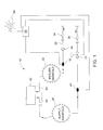
- FIG. 1 is an illustration of an exemplary fluid leak detection system indicated by reference number 10.
- the fluid leak detection system 10 includes a fluid conduit 20, a shutoff valve 22, an inlet flow meter 24, an inlet valve 26, a supply manifold 28, a fluid-cooled device 30, a return manifold 32, an outlet valve 34, an outlet flow meter 36, and a check valve 40.
- the fluid leak detection system 10 is part of a cooling circuit employed in a gas turbine (not shown), and the fluid-cooled device 30 is a gas turbine flame detector that detects the presence of a flame during gas turbine light-off.
- the fluid-cooled device 30 may be employed in a liquid fuel purge system, where the fluid-cooled device 30 is either a three way liquid fuel valve or a check valve.
- the fluid leak detection system 10 may be used in a variety of applications.
- a cooling medium such as, for example, water may flow through the fluid conduit 20 and is used to conduct heat away from the fluid-cooled device 30.
- the inlet valve 26 is a manual valve that is fluidly connected to the fluid conduit 20 and normally open during operation of the fluid leak detection system 10.
- the shutoff valve 22 is located downstream of the inlet valve 26 and is fluidly connected to and selectively blocks the amount of fluid that flows through the fluid conduit 20. Specifically, the shutoff valve 22 is employed to substantially block the flow of fluid to the fluid leak detection system 10 based on certain operating conditions. Downstream of the shutoff valve 22 is the inlet flow meter 24.
- the inlet flow meter 24 is a Coriolis flow meter that measures the mass flow rate of fluid traveling through the fluid conduit 20. However, it is to be understood that other types of flow meters may be used as well.
- the inlet flow meter 24 monitors an inlet 60 that is fluidly connected the fluid-cooled device 30 for an inlet temperature and an inlet flow rate.
- the supply manifold 28 is located downstream of the inlet flow meter 24, where the inlet flow meter 24 measures the flow rate and the temperature into the supply manifold 28.
- An outlet 62 of the fluid-cooled device 30 is fluidly connected to the return manifold 32.
- the return manifold 32 is located upstream of the outlet flow meter 36.
- the outlet flow meter 36 is a Coriolis flow meter that measures the mass flow rate of the fluid traveling through the fluid conduit 20.
- the outlet flow meter 36 monitors the outlet 62 of the fluid-cooled device 30 for an outlet temperature and an outlet flow rate.
- the outlet flow meter 36 is situated upstream of the check valve 40.
- the check valve 40 is employed to prevent the ingression of contaminants into the fluid leak detection system 10, and is also employed to reduce or substantially prevent the occurrence of backflow into the fluid conduit 20.
- the check valve 40 is located upstream of the outlet valve 34.
- the outlet valve 34 is typically a manual valve that is normally open during operation of the fluid leak detection system 10.
- the inlet valve 26 and the outlet valve 26 may be isolation valves typically employed during maintenance or system issues.
- the inlet flow meter 24 and the outlet flow meter 36 are both configured for monitoring fluid temperature and fluid flow rate of the fluid conduit 20 at their respective locations. Both the inlet flow meter 24 and the outlet flow meter 36 include substantially identical characteristics such as a drift versus process fluid curve, accuracy and tolerance. The drift versus process fluid curve represents the change in flow rate measurement accuracy of a flow meter that is caused by changes in ambient temperature. Moreover, in one embodiment, the inlet flow meter 24 and the outlet flow meter 36 are substantially identical and are produced by the same manufacturer.
- a controller 50 is provided and is in communication with the shutoff valve 22, the inlet flow meter 24, and the outlet flow meter 36.
- the controller 50 includes control logic for monitoring the inlet flow meter 24 and the outlet flow meter 36, as well as control logic for selectively actuating the shutoff valve 22.
- the controller 50 is a turbine controller that is employed for controlling various functions of a turbine (not shown) such as fuel and emissions control, as well as other functions of a gas turbine.
- the controller 50 includes a memory as well, where the drift versus process temperature curve, accuracy and tolerance of both the inlet flow meter 24 and the outlet flow meter 36 are stored in the memory of the controller 50.
- the memory of the controller 50 also includes a zero flow condition, where flow of the fluid in the fluid conduit 20 is substantially halted, and the inlet flow rate at the inlet 60 and the outlet flow rate at the outlet 62 are compared to one another and stored in the memory of the controller 50.
- a zero flow condition where flow of the fluid in the fluid conduit 20 is substantially halted, and the inlet flow rate at the inlet 60 and the outlet flow rate at the outlet 62 are compared to one another and stored in the memory of the controller 50.
- the flow of fluid through the fluid conduit 20 is substantially halted for a specified period of time where the fluid conduit 20 is filled with fluid.
- there is substantially zero flow of fluid through the fluid conduit 20 which may lead to a corresponding reading of zero flow output by both the inlet flow meter 24 and the outlet flow meter 36.
- the inlet flow meters 24 and outlet flow meters 36 may produce a non-zero flow rate during a time of substantially zero flow. In this case, the non-zero flow rate from the inlet flow meters 24
- the memory of the controller 50 also includes a set of data that indicates a percentage of error in flow rate in the fluid conduit 20 based on the temperature at the inlet 60 and the outlet 62.
- the difference in temperature between the inlet 60 and the outlet 62 is typically referred to as the sensing drift difference between the inlet flow meter 24 and the outlet flow meter 36.
- the percentage of error in flow rate in the fluid conduit 20 increases.
- the percentage of error in the flow rate may be based on the maximum flow rate in the fluid conduit 20.
- the controller 50 includes control logic for monitoring the inlet flow meter 24 for the inlet temperature and flow rate at the inlet 60, and the outlet flow meter 36 for the outlet temperature and flow rate at the outlet 62.
- the controller 50 includes control logic for determining the difference between the inlet temperature from the inlet flow meter 24 and the outlet temperature from the outlet flow meter 36.
- the controller 50 also includes control logic for determining the difference between the inlet flow rate from the inlet flow meter 24 and the outlet flow rate from the outlet flow meter 36.
- the controller 50 further includes control logic for calculating an actual flow rate difference between the inlet flow meter 24 and the outlet flow meter 36.
- the actual flow rate difference represents the real difference between the flow of fluid in the fluid conduit 20 at the inlet flow meter 24 and the outlet flow meter 36 during operation of the fluid leak detection system 10.
- the controller 50 calculates the actual flow rate difference based on the percentage of error in flow rate, the zero flow condition, and the difference between the inlet flow rate from the inlet flow meter 24 and the outlet flow rate from the outlet flow meter 36.
- the actual flow rate difference may be calculated by subtracting the inlet flow Flow in from the outlet flow Flow out .
- m errori m erroro
- m errori the error of the mass flow rate at the inlet flow meter 24
- m erroro the error of the mass flow rate at the outlet flow meter 36.
- m readi the mass flow rate read by the inlet flow meter 24
- m actuali the actual mass flow rate at the inlet flow meter 24
- m errori the error in mass flow rate at the inlet flow meter 24 read by the controller 50.
- m reado is the mass flow rate read by the outlet flow meter 36
- m actualo is the actual mass flow rate at the outlet flow meter 36
- m erroro is the error in mass flow rate at the inlet flow meter 36 read by the controller 50.
- the controller 50 includes control logic for indicating a leak condition in the fluid leak detection system 10 if the actual flow rate difference is above a threshold value. For example, in one embodiment if the difference between the mass flow rate m readi read by the inlet flow meter 24 and the mass flow rate m reado read by the outlet flow meter 36 is above the threshold value, then the controller 50 determines that a leak condition in the fluid leak detection system 10 has occurred.
- the fluid leak detection system 10 includes an indicator or an alarm 80 that is in communication with the controller 50, where the alarm 80 emits a visual indicator or sound to alert an operator that a leak condition has occurred.
- the controller 50 may also be in communication with a computing screen, which is not illustrated, where the controller 50 sends a signal to the screen to display a visual indicator that informs an operator that the leak condition has occurred.
- the controller 50 may include control logic for calculating a level one leak condition, which occurs if the actual flow rate difference is above a level one threshold value. In this situation, the controller 50 includes control logic for sending a signal to the alarm 80. The alarm will then emit a level one tone or visual indicator. A level two leak condition may occur as well if the actual flow rate difference is above a level two threshold value. The level two threshold value is greater than the level one threshold value. During the level two leak the controller 50 includes control logic for sending a signal to the alarm 80 for emitting a level two tone or indicator. The level two tone or indicator is typically louder or brighter than the level one tone or indictor, in an effort to alert an operator of a leak condition that may require greater attention.
- the controller 50 is in communication with a turbine (not shown) for sending a signal to the turbine indicating that a false outage condition is created or induced in an effort to substantially reduce the risk of turbine trip and to reduce the amount of fluid leakage.
- the controller 50 further includes control logic for sending a signal to the shutoff valve 22 to substantially block the flow of fluid to the inlet 60 of the fluid-cooled device 30.
Landscapes
- Physics & Mathematics (AREA)
- General Physics & Mathematics (AREA)
- Fluid Mechanics (AREA)
- Examining Or Testing Airtightness (AREA)
- Measuring Volume Flow (AREA)
Abstract
Description
- The subject matter disclosed herein relates to a fluid leak detection system, and more specifically to a fluid leak detection system having a controller with control logic for monitoring the fluid leak detection system and determining if a leak condition exists.
- Traditionally, gas turbine flame detectors have been used to ensure the presence of a flame during gas turbine light-off. Some flame detectors employ a cooling coil that uses water as a cooling medium to keep a flame detector sensor below a threshold temperature. However, a leak may occur in the cooling water circuit. Leakage of the cooling water may cause a casing of the gas turbine or components located within the casing to need replacement. Replacing the casing of the gas turbine or the components located within the casing may become time-consuming and costly.
- Cooling water may also be employed to cool a liquid fuel purge system as well in a gas turbine. Specifically, cooling water may be used to cool a three way liquid fuel valve. Cooling water may also be employed to cool check valves of the liquid fuel purge system. Specifically, cooling water is used to maintain an internal check valve or three way valve temperature below the coking threshold of the liquid fuel. However, a leak may also occur in the cooling water circuit of the liquid fuel purge system, which may also cause the water cooled valve to operate incorrectly. The leak may also cause casing or other gas turbine component issues.
- According to one aspect of the invention, a fluid leak detection system is provided and includes a fluid conduit, a fluid-cooled device having an inlet and an outlet, an inlet flow meter, an outlet flow meter, and a controller. The inlet flow meter is fluidly connected to the fluid conduit. The inlet flow meter monitors the inlet of the fluid-cooled device for an inlet temperature and an inlet flow rate. The inlet flow meter has an inlet flow meter drift versus process fluid temperature curve. The outlet flow meter is fluidly connected to the fluid conduit. The outlet flow meter monitors the outlet of the fluid-cooled device for an outlet temperature and an outlet flow rate. The outlet flow meter has an outlet flow meter drift versus process fluid temperature curve. The controller is in communication with the inlet flow meter and the outlet flow meter. The controller includes a memory having the inlet flow meter drift versus process fluid temperature curve and the outlet flow meter drift versus process fluid temperature curve stored therein. The inlet flow meter drift versus process fluid temperature curve is substantially identical to the outlet flow meter drift versus process fluid temperature curve. A zero flow condition where flow of fluid in the fluid conduit is substantially halted and the inlet flow rate and the outlet flow rate are saved in the memory of the controller as well.
- The controller includes control logic for monitoring the inlet flow meter for the inlet temperature and the inlet flow rate and the outlet flow meter for the outlet temperature and the outlet flow rate. The controller also includes control logic for compensating measurement drift due to the temperature of the process fluid and the percentage of error in the respective flow rates. Specifically, the controller includes control logic for determining the difference between the inlet temperature and the outlet temperature. The memory of the controller includes a set of data stored therein that indicates a percentage of error in flow rate based on the difference between the inlet temperature and the outlet temperature. The controller further includes control logic for determining the difference between the inlet flow rate and the outlet flow rate. The controller includes control logic for calculating an actual flow rate difference between the inlet flow rate and the outlet flow rate. The actual flow rate difference is based on the percentage of error in flow rate, the difference between the inlet flow rate and the outlet flow rate, and the zero flow condition. The controller also includes control logic for indicating a leak condition in the fluid leak detection system if the actual flow rate difference is above a threshold value.
- These and other advantages and features will become more apparent from the following description taken in conjunction with the drawings.
- Embodiments of the present invention will now be described, by way of example only, with reference to the accompanying drawings in which:
-
FIG. 1 is an exemplary schematic illustration of a fluid leak detection system. - The detailed description explains embodiments of the invention, together with advantages and features, by way of example with reference to the drawings.
- As used herein the terms module and sub-module refer to an application specific integrated circuit (ASIC), an electronic circuit, a processor (shared, dedicated, or group) and memory that executes one or more software or firmware programs, a combinational logic circuit, and/or other suitable components that provide the described functionality.
-
FIG. 1 is an illustration of an exemplary fluid leak detection system indicated byreference number 10. The fluidleak detection system 10 includes afluid conduit 20, ashutoff valve 22, aninlet flow meter 24, aninlet valve 26, asupply manifold 28, a fluid-cooleddevice 30, areturn manifold 32, anoutlet valve 34, anoutlet flow meter 36, and acheck valve 40. In one exemplary embodiment, the fluidleak detection system 10 is part of a cooling circuit employed in a gas turbine (not shown), and the fluid-cooleddevice 30 is a gas turbine flame detector that detects the presence of a flame during gas turbine light-off. Alternatively, in another exemplary embodiment the fluid-cooleddevice 30 may be employed in a liquid fuel purge system, where the fluid-cooleddevice 30 is either a three way liquid fuel valve or a check valve. However, it is to be understood that the fluidleak detection system 10 may be used in a variety of applications. In one embodiment a cooling medium such as, for example, water may flow through thefluid conduit 20 and is used to conduct heat away from the fluid-cooleddevice 30. - The
inlet valve 26 is a manual valve that is fluidly connected to thefluid conduit 20 and normally open during operation of the fluidleak detection system 10. Theshutoff valve 22 is located downstream of theinlet valve 26 and is fluidly connected to and selectively blocks the amount of fluid that flows through thefluid conduit 20. Specifically, theshutoff valve 22 is employed to substantially block the flow of fluid to the fluidleak detection system 10 based on certain operating conditions. Downstream of theshutoff valve 22 is theinlet flow meter 24. In one embodiment, theinlet flow meter 24 is a Coriolis flow meter that measures the mass flow rate of fluid traveling through thefluid conduit 20. However, it is to be understood that other types of flow meters may be used as well. Theinlet flow meter 24 monitors aninlet 60 that is fluidly connected the fluid-cooleddevice 30 for an inlet temperature and an inlet flow rate. Thesupply manifold 28 is located downstream of theinlet flow meter 24, where theinlet flow meter 24 measures the flow rate and the temperature into thesupply manifold 28. - An
outlet 62 of the fluid-cooleddevice 30 is fluidly connected to thereturn manifold 32. Thereturn manifold 32 is located upstream of theoutlet flow meter 36. In one embodiment, theoutlet flow meter 36 is a Coriolis flow meter that measures the mass flow rate of the fluid traveling through thefluid conduit 20. However other types of flow meters may be used as well. Theoutlet flow meter 36 monitors theoutlet 62 of the fluid-cooleddevice 30 for an outlet temperature and an outlet flow rate.. Theoutlet flow meter 36 is situated upstream of thecheck valve 40. Thecheck valve 40 is employed to prevent the ingression of contaminants into the fluidleak detection system 10, and is also employed to reduce or substantially prevent the occurrence of backflow into thefluid conduit 20. Thecheck valve 40 is located upstream of theoutlet valve 34. Theoutlet valve 34 is typically a manual valve that is normally open during operation of the fluidleak detection system 10. Theinlet valve 26 and theoutlet valve 26 may be isolation valves typically employed during maintenance or system issues. - The
inlet flow meter 24 and theoutlet flow meter 36 are both configured for monitoring fluid temperature and fluid flow rate of thefluid conduit 20 at their respective locations. Both theinlet flow meter 24 and theoutlet flow meter 36 include substantially identical characteristics such as a drift versus process fluid curve, accuracy and tolerance. The drift versus process fluid curve represents the change in flow rate measurement accuracy of a flow meter that is caused by changes in ambient temperature. Moreover, in one embodiment, theinlet flow meter 24 and theoutlet flow meter 36 are substantially identical and are produced by the same manufacturer. - A
controller 50 is provided and is in communication with theshutoff valve 22, theinlet flow meter 24, and theoutlet flow meter 36. Specifically, thecontroller 50 includes control logic for monitoring theinlet flow meter 24 and theoutlet flow meter 36, as well as control logic for selectively actuating theshutoff valve 22. In one exemplary embodiment, thecontroller 50 is a turbine controller that is employed for controlling various functions of a turbine (not shown) such as fuel and emissions control, as well as other functions of a gas turbine. Thecontroller 50 includes a memory as well, where the drift versus process temperature curve, accuracy and tolerance of both theinlet flow meter 24 and theoutlet flow meter 36 are stored in the memory of thecontroller 50. - The memory of the
controller 50 also includes a zero flow condition, where flow of the fluid in thefluid conduit 20 is substantially halted, and the inlet flow rate at theinlet 60 and the outlet flow rate at theoutlet 62 are compared to one another and stored in the memory of thecontroller 50. Specifically, during zeroing of thecontroller 50, the flow of fluid through thefluid conduit 20 is substantially halted for a specified period of time where thefluid conduit 20 is filled with fluid. As a result, there is substantially zero flow of fluid through thefluid conduit 20, which may lead to a corresponding reading of zero flow output by both theinlet flow meter 24 and theoutlet flow meter 36. However, sometimes theinlet flow meters 24 andoutlet flow meters 36 may produce a non-zero flow rate during a time of substantially zero flow. In this case, the non-zero flow rate from theinlet flow meters 24 andoutlet flow meters 36 may be used as the zero flow condition. - The memory of the
controller 50 also includes a set of data that indicates a percentage of error in flow rate in thefluid conduit 20 based on the temperature at theinlet 60 and theoutlet 62. The difference in temperature between theinlet 60 and theoutlet 62 is typically referred to as the sensing drift difference between theinlet flow meter 24 and theoutlet flow meter 36. As the difference between the temperature at theinlet 60 and theoutlet 62 increase, the percentage of error in flow rate in thefluid conduit 20 increases. The percentage of error in the flow rate may be based on the maximum flow rate in thefluid conduit 20. - The
controller 50 includes control logic for monitoring theinlet flow meter 24 for the inlet temperature and flow rate at theinlet 60, and theoutlet flow meter 36 for the outlet temperature and flow rate at theoutlet 62. Thecontroller 50 includes control logic for determining the difference between the inlet temperature from theinlet flow meter 24 and the outlet temperature from theoutlet flow meter 36. Thecontroller 50 also includes control logic for determining the difference between the inlet flow rate from theinlet flow meter 24 and the outlet flow rate from theoutlet flow meter 36. - The
controller 50 further includes control logic for calculating an actual flow rate difference between theinlet flow meter 24 and theoutlet flow meter 36. Specifically, the actual flow rate difference represents the real difference between the flow of fluid in thefluid conduit 20 at theinlet flow meter 24 and theoutlet flow meter 36 during operation of the fluidleak detection system 10. Thecontroller 50 calculates the actual flow rate difference based on the percentage of error in flow rate, the zero flow condition, and the difference between the inlet flow rate from theinlet flow meter 24 and the outlet flow rate from theoutlet flow meter 36. The actual flow rate difference may be calculated by subtracting the inlet flow Flowin from the outlet flow Flowout. Specifically, because theinlet flow meter 24 and theoutlet flow meter 36 both share the same error and tolerance,
where merrori is the error of the mass flow rate at theinlet flow meter 24 and merroro is the error of the mass flow rate at theoutlet flow meter 36. Moreover, when the flow of fluid in thefluid conduit 20 is substantially halted, then
and
where mreadi is the mass flow rate read by theinlet flow meter 24, mactuali is the actual mass flow rate at theinlet flow meter 24, and merrori is the error in mass flow rate at theinlet flow meter 24 read by thecontroller 50. Also, mreado is the mass flow rate read by theoutlet flow meter 36, mactualo is the actual mass flow rate at theoutlet flow meter 36, and merroro is the error in mass flow rate at theinlet flow meter 36 read by thecontroller 50. In the event there is fluid flow through thefluid conduit 20 and the fluidleak detection system 10 is substantially leak free, then:
and
- The
controller 50 includes control logic for indicating a leak condition in the fluidleak detection system 10 if the actual flow rate difference is above a threshold value. For example, in one embodiment if the difference between the mass flow rate mreadi read by theinlet flow meter 24 and the mass flow rate mreado read by theoutlet flow meter 36 is above the threshold value, then thecontroller 50 determines that a leak condition in the fluidleak detection system 10 has occurred. Specifically, in one embodiment the fluidleak detection system 10 includes an indicator or analarm 80 that is in communication with thecontroller 50, where thealarm 80 emits a visual indicator or sound to alert an operator that a leak condition has occurred. In one example, thecontroller 50 may also be in communication with a computing screen, which is not illustrated, where thecontroller 50 sends a signal to the screen to display a visual indicator that informs an operator that the leak condition has occurred. - Several types of leak conditions exist. In one embodiment, the
controller 50 may include control logic for calculating a level one leak condition, which occurs if the actual flow rate difference is above a level one threshold value. In this situation, thecontroller 50 includes control logic for sending a signal to thealarm 80. The alarm will then emit a level one tone or visual indicator. A level two leak condition may occur as well if the actual flow rate difference is above a level two threshold value. The level two threshold value is greater than the level one threshold value. During the level two leak thecontroller 50 includes control logic for sending a signal to thealarm 80 for emitting a level two tone or indicator. The level two tone or indicator is typically louder or brighter than the level one tone or indictor, in an effort to alert an operator of a leak condition that may require greater attention. - In addition to the
alarm 80, two different approaches may be used as well if the level two leak condition occurs. In a first approach, thecontroller 50 is in communication with a turbine (not shown) for sending a signal to the turbine indicating that a false outage condition is created or induced in an effort to substantially reduce the risk of turbine trip and to reduce the amount of fluid leakage. Alternatively, in another embodiment thecontroller 50 further includes control logic for sending a signal to theshutoff valve 22 to substantially block the flow of fluid to theinlet 60 of the fluid-cooleddevice 30. Thus, in the event a leak is detected, fluid may no longer flow through thefluid conduit 20, which may reduce the occurrence of fluid leakage in the system. - While the invention has been described in detail in connection with only a limited number of embodiments, it should be readily understood that the invention is not limited to such disclosed embodiments. Rather, the invention can be modified to incorporate any number of variations, alterations, substitutions or equivalent arrangements not heretofore described, but which are commensurate with the spirit and scope of the invention. Additionally, while various embodiments of the invention have been described, it is to be understood that aspects of the invention may include only some of the described embodiments. Accordingly, the invention is not to be seen as limited by the foregoing description, but is only limited by the scope of the appended claims.
Claims (14)
- A fluid leak detection system (10), comprising:a fluid conduit (20);a fluid-cooled device (30) having an inlet (60) and an outlet (62);an inlet flow meter (24) fluidly connected to the fluid conduit (20), the inlet flow meter (24) monitoring the inlet (60) of the fluid-cooled device (30) for an inlet (60) temperature and an inlet flow rate, the inlet flow meter (24) having an inlet flow meter (24) drift versus process fluid temperature curve;an outlet flow meter (36) fluidly connected to the fluid conduit (20), the outlet flow meter (36) monitoring the outlet (62) of the fluid-cooled device (30) for an outlet (62) temperature and an outlet flow rate, the outlet flow meter (36) having an outlet flow meter (36) drift versus process fluid temperature curve;a controller (50) in communication with the inlet flow meter (24) and the outlet flow meter (36), the controller (50) including a memory having the inlet flow meter (24) drift versus process fluid temperature curve and the outlet flow meter (36) drift versus process fluid temperature curve stored therein, the inlet flow meter (24) drift versus process fluid temperature curve substantially identical to the outlet flow meter (36) drift versus process fluid temperature curve, and a zero flow condition where a fluid flow in the fluid conduit (20) is substantially halted and values of the inlet flow rate and the outlet flow rate are saved in the memory of the controller (50), the controller (50) including:a control logic for monitoring the inlet flow meter (24) for the inlet temperature and the inlet flow rate and the outlet flow meter (36) for the outlet (62) temperature and the outlet flow rate;a control logic for determining the difference between the inlet (60) temperature and the outlet (62) temperature, the memory of the controller (50) including a set of data stored therein that indicates a percentage of error in flow rate based on the difference between the inlet (60) temperature and the outlet (62) temperature;a control logic for determining the difference between the inlet flow rate and the outlet flow rate;a control logic for calculating an actual flow rate difference between the inlet flow rate and the outlet flow rate, the actual flow rate difference based on the percentage of error in flow rate, the difference between the inlet flow rate and the outlet flow rate, and the zero flow condition; anda control logic for indicating a leak condition in the fluid leak detection system (10) if the actual flow rate difference is above a threshold value.
- The fluid leak detection system (10) of claim 1, further comprising an inlet valve (26) fluidly connected to the fluid conduit (20) an outlet valve (34) fluidly connected to the fluid conduit (20), wherein the inlet valve (26) and the outlet valve (34) are manual valves.
- The fluid leak detection system (10) of claim 1 or 2, further comprising a shutoff valve (22) fluidly connected to and selectively blocking the fluid flow through the fluid conduit (20).
- The fluid leak detection system (10) of claim 3, wherein the controller (50) is in communication with the shutoff valve (22), and wherein the controller (50) includes control logic for selectively sending a signal to the shutoff valve (22) to substantially block the flow of fluid to the inlet (60) of the fluid-cooled device (30).
- The fluid leak detection system (10) of any of claims 1 to 4, wherein the threshold value further includes a level one threshold value and a level two threshold value, wherein the level two threshold value is greater than the level one threshold value.
- The fluid leak detection system (10) of claim 5, wherein if the controller (50) detects the level one threshold value, then controller (50) includes control logic for sending a signal to an alarm (80), wherein the signal instructs the alarm (80) to emit one of a level one tone and a level one visual indicator.
- The fluid leak detection system (10) of claim 5 or 6, wherein if the controller (50) detects the level two threshold value, then controller (50) includes control logic for sending a signal to an alarm (80), wherein the signal instructs the alarm (80) to emit one of a level two tone and a level two visual indicator.
- The fluid leak detection system (10) of claim 7, wherein if the controller (50) detects the level two threshold value, then controller (50) includes control logic for sending a signal to the shutoff valve (22) to substantially block the flow of fluid to the inlet (60) of the fluid-cooled device (30).
- The fluid leak detection system (10) of claim 7, wherein if the controller (50) detects the level two threshold value, then controller (50) includes control logic for sending a signal to a turbine indicating that a false outage condition is to be induced.
- The fluid leak detection system (10) of any preceding claim, further comprising a check valve (40) fluidly connected to the fluid conduit (20) and located downstream of the outlet flow meter (36).
- The fluid leak detection system of any preceding claim, wherein the fluid-cooled device (30) is one of a gas turbine flame detector, a three way liquid fuel valve, and a check valve of a liquid fuel purge system.
- The fluid leak detection system of any preceding claim, wherein the inlet flow meter (24) and the outlet flow meter (36) are both Coriolis flow meters for measuring a mass flow rate of the fluid flow traveling through the fluid conduit (20).
- The fluid leak detection system of any preceding claim, wherein the inlet flow meter (24) and the outlet flow meter (36) include substantially identical accuracy and tolerance.
- A turbine having the fluid leak detection system of any of claims 1 to 13.
Applications Claiming Priority (1)
| Application Number | Priority Date | Filing Date | Title |
|---|---|---|---|
| US13/166,973 US20120324985A1 (en) | 2011-06-23 | 2011-06-23 | Fluid leak detection system |
Publications (1)
| Publication Number | Publication Date |
|---|---|
| EP2538194A1 true EP2538194A1 (en) | 2012-12-26 |
Family
ID=46583848
Family Applications (1)
| Application Number | Title | Priority Date | Filing Date |
|---|---|---|---|
| EP12172565A Withdrawn EP2538194A1 (en) | 2011-06-23 | 2012-06-19 | Fluid Leak Detection System |
Country Status (3)
| Country | Link |
|---|---|
| US (1) | US20120324985A1 (en) |
| EP (1) | EP2538194A1 (en) |
| CN (1) | CN102840034A (en) |
Cited By (3)
| Publication number | Priority date | Publication date | Assignee | Title |
|---|---|---|---|---|
| CN103278221A (en) * | 2013-06-07 | 2013-09-04 | 重庆前卫克罗姆表业有限责任公司 | Detection equipment used for finished intelligent meter |
| AU2014405569C1 (en) * | 2014-09-04 | 2019-06-20 | Micro Motion, Inc. | Differential flowmeter tool |
| FR3147365A1 (en) * | 2023-03-27 | 2024-10-04 | Safran Helicopter Engines | Permeability measurement of a turbomachine injection system |
Families Citing this family (35)
| Publication number | Priority date | Publication date | Assignee | Title |
|---|---|---|---|---|
| CA3116787C (en) | 2010-06-16 | 2023-07-11 | Mueller International, Llc | Infrastructure monitoring devices, systems, and methods |
| US9772250B2 (en) | 2011-08-12 | 2017-09-26 | Mueller International, Llc | Leak detector and sensor |
| US9037422B2 (en) * | 2012-08-13 | 2015-05-19 | Invensys Systems, Inc. | Leak detection in fluid conducting conduit |
| US9506785B2 (en) | 2013-03-15 | 2016-11-29 | Rain Bird Corporation | Remote flow rate measuring |
| CN103321635B (en) * | 2013-06-09 | 2016-06-15 | 中煤矿山建设集团有限责任公司 | A kind of accurate warning of freezing apparatus saline leakage |
| US20150346049A1 (en) * | 2014-06-02 | 2015-12-03 | Mechanical Testing Services, Llc | Quantitative Leak Detection System and Method |
| JP6501380B2 (en) * | 2014-07-01 | 2019-04-17 | 三菱重工コンプレッサ株式会社 | Multistage compressor system, control device, abnormality determination method and program |
| AU2015301406B2 (en) * | 2014-08-14 | 2020-07-16 | Reliance Worldwide Corporation | Methods and apparatus for fluid flow monitoring and leak detection |
| MX370819B (en) | 2014-08-14 | 2020-01-08 | Reliance Worldwide Corp | Devices and system for channeling and automatic monitoring of fluid flow in fluid distribution systems |
| GB2553681B (en) | 2015-01-07 | 2019-06-26 | Homeserve Plc | Flow detection device |
| GB201501935D0 (en) | 2015-02-05 | 2015-03-25 | Tooms Moore Consulting Ltd And Trow Consulting Ltd | Water flow analysis |
| US9696235B2 (en) | 2015-03-18 | 2017-07-04 | Lenovo Enterprise Solutions (Singapore) Pte. Ltd. | Managing water leakage from a water cooling system within a compute node |
| US10125711B2 (en) | 2015-07-29 | 2018-11-13 | General Electric Company | Systems for fuel delivery |
| WO2017039683A1 (en) | 2015-09-04 | 2017-03-09 | Hewlett Packard Enterprise Development Lp | Valve failure predictions |
| US10837438B2 (en) | 2015-09-04 | 2020-11-17 | Hewlett Packard Enterprise Development Lp | Pump based issue identification |
| US10283857B2 (en) | 2016-02-12 | 2019-05-07 | Mueller International, Llc | Nozzle cap multi-band antenna assembly |
| US10305178B2 (en) | 2016-02-12 | 2019-05-28 | Mueller International, Llc | Nozzle cap multi-band antenna assembly |
| USD800591S1 (en) | 2016-03-31 | 2017-10-24 | Homeserve Plc | Flowmeter |
| WO2018013857A1 (en) | 2016-07-13 | 2018-01-18 | Rain Bird Corporation | Flow sensor |
| US10473494B2 (en) | 2017-10-24 | 2019-11-12 | Rain Bird Corporation | Flow sensor |
| US11300365B2 (en) | 2018-06-19 | 2022-04-12 | General Electric Company | Heat exchanger and leak detection system |
| CN109029055A (en) * | 2018-07-05 | 2018-12-18 | 亓培荣 | A kind of heat exchanger convenient for leak detection |
| US10859462B2 (en) | 2018-09-04 | 2020-12-08 | Mueller International, Llc | Hydrant cap leak detector with oriented sensor |
| US11342656B2 (en) | 2018-12-28 | 2022-05-24 | Mueller International, Llc | Nozzle cap encapsulated antenna system |
| US11662242B2 (en) | 2018-12-31 | 2023-05-30 | Rain Bird Corporation | Flow sensor gauge |
| US11473993B2 (en) | 2019-05-31 | 2022-10-18 | Mueller International, Llc | Hydrant nozzle cap |
| US20200407238A1 (en) * | 2019-06-26 | 2020-12-31 | Haier Us Appliance Solutions, Inc. | Connected water treatment system with remotely operated shut-off valve |
| EP3772048B1 (en) * | 2019-07-31 | 2021-06-16 | Siemens Aktiengesellschaft | Overpressure encapsulation |
| US11542690B2 (en) | 2020-05-14 | 2023-01-03 | Mueller International, Llc | Hydrant nozzle cap adapter |
| CN112051014A (en) * | 2020-09-21 | 2020-12-08 | 贵州安吉航空精密铸造有限责任公司 | Shell airtightness detection device and shell airtightness detection method |
| CN114562365B (en) * | 2022-02-25 | 2023-06-16 | 河南柴油机重工有限责任公司 | Control method for monitoring oil leakage and water leakage of diesel engine |
| US12578245B2 (en) | 2022-10-28 | 2026-03-17 | Mueller International, Llc | Self-leveling sensor assembly |
| US12443208B2 (en) | 2023-02-08 | 2025-10-14 | Rain Bird Corporation | Control zone devices, systems and methods |
| CN116952485A (en) * | 2023-07-27 | 2023-10-27 | 上海云懋空气处理设备有限公司 | Sealing performance detection device, rotary dehumidifier and sealing performance detection method |
| CN117538031B (en) * | 2023-10-11 | 2024-06-04 | 无锡宝丰电力设备有限公司 | Intelligent valve on-line monitoring system |
Citations (3)
| Publication number | Priority date | Publication date | Assignee | Title |
|---|---|---|---|---|
| US20030110834A1 (en) * | 1999-11-18 | 2003-06-19 | Gunther Weber | Method and apparatus for detecting leaks |
| US20090148800A1 (en) * | 2007-12-05 | 2009-06-11 | Berry Metal Company | Furnace panel leak detection system |
| WO2011019345A1 (en) * | 2009-08-12 | 2011-02-17 | Micro Motion, Inc. | Method and apparatus for determining a zero offset in a vibrating flow meter |
Family Cites Families (3)
| Publication number | Priority date | Publication date | Assignee | Title |
|---|---|---|---|---|
| DE1922986C3 (en) * | 1969-05-06 | 1975-09-18 | Erdoel-Raffinerie Mannheim Gmbh, 6800 Mannheim | Procedure for monitoring leaks in liquid lines |
| US5524084A (en) * | 1994-12-30 | 1996-06-04 | Hewlett-Packard Company | Method and apparatus for improved flow and pressure measurement and control |
| US6526358B1 (en) * | 1999-10-01 | 2003-02-25 | General Electric Company | Model-based detection of leaks and blockages in fluid handling systems |
-
2011
- 2011-06-23 US US13/166,973 patent/US20120324985A1/en not_active Abandoned
-
2012
- 2012-06-19 EP EP12172565A patent/EP2538194A1/en not_active Withdrawn
- 2012-06-25 CN CN2012102138873A patent/CN102840034A/en active Pending
Patent Citations (3)
| Publication number | Priority date | Publication date | Assignee | Title |
|---|---|---|---|---|
| US20030110834A1 (en) * | 1999-11-18 | 2003-06-19 | Gunther Weber | Method and apparatus for detecting leaks |
| US20090148800A1 (en) * | 2007-12-05 | 2009-06-11 | Berry Metal Company | Furnace panel leak detection system |
| WO2011019345A1 (en) * | 2009-08-12 | 2011-02-17 | Micro Motion, Inc. | Method and apparatus for determining a zero offset in a vibrating flow meter |
Cited By (5)
| Publication number | Priority date | Publication date | Assignee | Title |
|---|---|---|---|---|
| CN103278221A (en) * | 2013-06-07 | 2013-09-04 | 重庆前卫克罗姆表业有限责任公司 | Detection equipment used for finished intelligent meter |
| CN103278221B (en) * | 2013-06-07 | 2016-02-10 | 重庆前卫克罗姆表业有限责任公司 | For the checkout equipment of intelligent telogenesis table |
| AU2014405569C1 (en) * | 2014-09-04 | 2019-06-20 | Micro Motion, Inc. | Differential flowmeter tool |
| US10663338B2 (en) | 2014-09-04 | 2020-05-26 | Micro Motion, Inc. | Differential flowmeter tool |
| FR3147365A1 (en) * | 2023-03-27 | 2024-10-04 | Safran Helicopter Engines | Permeability measurement of a turbomachine injection system |
Also Published As
| Publication number | Publication date |
|---|---|
| US20120324985A1 (en) | 2012-12-27 |
| CN102840034A (en) | 2012-12-26 |
Similar Documents
| Publication | Publication Date | Title |
|---|---|---|
| EP2538194A1 (en) | Fluid Leak Detection System | |
| EP2615432A1 (en) | Fluid leak detection system | |
| CN102667422B (en) | Self-monitoring flow measurement device and method for its operation | |
| US8386084B2 (en) | Gas shutoff device | |
| JPH0961284A (en) | Pipe leakage monitoring device | |
| JP5689947B2 (en) | Automatic operation method of measuring device for particle measurement in gas | |
| CN101960266B (en) | Gas meter and gas safety system | |
| JP2013524164A5 (en) | ||
| US11480493B2 (en) | Gas safety device | |
| EP2994724A1 (en) | Consumption meter with selectable legal registers | |
| US8578763B2 (en) | System and method for fuel system health monitoring | |
| WO2010087185A1 (en) | Gas shutoff device | |
| KR20040030352A (en) | Gas shutoff device | |
| CN118913553A (en) | Self-adaptive pressure regulating system of air tightness detection equipment | |
| CN102279024B (en) | For the method and apparatus of detecting liquids inside gas return pipeline | |
| US11525754B2 (en) | Leak detection system and method | |
| WO2010041456A1 (en) | Gas circuit breaker | |
| CN113811745B (en) | Gas safety device | |
| JP5950834B2 (en) | Abnormality measuring device judgment system | |
| JP2001296162A (en) | Gas security equipment | |
| KR20210128764A (en) | Leakage and freezing detection system of pressure pipe/tube having dead-end type field transmitter | |
| JP2009168739A (en) | Gas meter with self-diagnostic function | |
| JP5299039B2 (en) | Gas shut-off device | |
| JP5213220B2 (en) | Flow rate measuring device, communication system, flow rate measuring method, flow rate measuring program, and fluid supply system | |
| CN116717736A (en) | AI artificial intelligence gas leakage early warning monitoring method |
Legal Events
| Date | Code | Title | Description |
|---|---|---|---|
| PUAI | Public reference made under article 153(3) epc to a published international application that has entered the european phase |
Free format text: ORIGINAL CODE: 0009012 |
|
| AK | Designated contracting states |
Kind code of ref document: A1 Designated state(s): AL AT BE BG CH CY CZ DE DK EE ES FI FR GB GR HR HU IE IS IT LI LT LU LV MC MK MT NL NO PL PT RO RS SE SI SK SM TR |
|
| AX | Request for extension of the european patent |
Extension state: BA ME |
|
| 17P | Request for examination filed |
Effective date: 20130626 |
|
| RBV | Designated contracting states (corrected) |
Designated state(s): AL AT BE BG CH CY CZ DE DK EE ES FI FR GB GR HR HU IE IS IT LI LT LU LV MC MK MT NL NO PL PT RO RS SE SI SK SM TR |
|
| GRAP | Despatch of communication of intention to grant a patent |
Free format text: ORIGINAL CODE: EPIDOSNIGR1 |
|
| RIC1 | Information provided on ipc code assigned before grant |
Ipc: G01F 25/00 20060101ALI20140422BHEP Ipc: F01P 11/18 20060101ALI20140422BHEP Ipc: G01M 3/32 20060101AFI20140422BHEP |
|
| INTG | Intention to grant announced |
Effective date: 20140520 |
|
| STAA | Information on the status of an ep patent application or granted ep patent |
Free format text: STATUS: THE APPLICATION IS DEEMED TO BE WITHDRAWN |
|
| 18D | Application deemed to be withdrawn |
Effective date: 20141001 |