EP2538172A1 - Method for adjusting optical displacement sensor and method for manufacturing optical displacement sensor - Google Patents
Method for adjusting optical displacement sensor and method for manufacturing optical displacement sensor Download PDFInfo
- Publication number
- EP2538172A1 EP2538172A1 EP11828506A EP11828506A EP2538172A1 EP 2538172 A1 EP2538172 A1 EP 2538172A1 EP 11828506 A EP11828506 A EP 11828506A EP 11828506 A EP11828506 A EP 11828506A EP 2538172 A1 EP2538172 A1 EP 2538172A1
- Authority
- EP
- European Patent Office
- Prior art keywords
- light
- lens
- receiving
- displacement sensor
- receiving lens
- Prior art date
- Legal status (The legal status is an assumption and is not a legal conclusion. Google has not performed a legal analysis and makes no representation as to the accuracy of the status listed.)
- Granted
Links
Images




Classifications
-
- G—PHYSICS
- G01—MEASURING; TESTING
- G01S—RADIO DIRECTION-FINDING; RADIO NAVIGATION; DETERMINING DISTANCE OR VELOCITY BY USE OF RADIO WAVES; LOCATING OR PRESENCE-DETECTING BY USE OF THE REFLECTION OR RERADIATION OF RADIO WAVES; ANALOGOUS ARRANGEMENTS USING OTHER WAVES
- G01S17/00—Systems using the reflection or reradiation of electromagnetic waves other than radio waves, e.g. lidar systems
- G01S17/02—Systems using the reflection of electromagnetic waves other than radio waves
- G01S17/06—Systems determining position data of a target
- G01S17/46—Indirect determination of position data
- G01S17/48—Active triangulation systems, i.e. using the transmission and reflection of electromagnetic waves other than radio waves
-
- G—PHYSICS
- G01—MEASURING; TESTING
- G01B—MEASURING LENGTH, THICKNESS OR SIMILAR LINEAR DIMENSIONS; MEASURING ANGLES; MEASURING AREAS; MEASURING IRREGULARITIES OF SURFACES OR CONTOURS
- G01B11/00—Measuring arrangements characterised by the use of optical techniques
- G01B11/02—Measuring arrangements characterised by the use of optical techniques for measuring length, width or thickness
- G01B11/026—Measuring arrangements characterised by the use of optical techniques for measuring length, width or thickness by measuring distance between sensor and object
-
- G—PHYSICS
- G01—MEASURING; TESTING
- G01C—MEASURING DISTANCES, LEVELS OR BEARINGS; SURVEYING; NAVIGATION; GYROSCOPIC INSTRUMENTS; PHOTOGRAMMETRY OR VIDEOGRAMMETRY
- G01C3/00—Measuring distances in line of sight; Optical rangefinders
- G01C3/02—Details
- G01C3/06—Use of electric means to obtain final indication
-
- G—PHYSICS
- G01—MEASURING; TESTING
- G01S—RADIO DIRECTION-FINDING; RADIO NAVIGATION; DETERMINING DISTANCE OR VELOCITY BY USE OF RADIO WAVES; LOCATING OR PRESENCE-DETECTING BY USE OF THE REFLECTION OR RERADIATION OF RADIO WAVES; ANALOGOUS ARRANGEMENTS USING OTHER WAVES
- G01S7/00—Details of systems according to groups G01S13/00, G01S15/00, G01S17/00
- G01S7/48—Details of systems according to groups G01S13/00, G01S15/00, G01S17/00 of systems according to group G01S17/00
- G01S7/481—Constructional features, e.g. arrangements of optical elements
-
- G—PHYSICS
- G01—MEASURING; TESTING
- G01S—RADIO DIRECTION-FINDING; RADIO NAVIGATION; DETERMINING DISTANCE OR VELOCITY BY USE OF RADIO WAVES; LOCATING OR PRESENCE-DETECTING BY USE OF THE REFLECTION OR RERADIATION OF RADIO WAVES; ANALOGOUS ARRANGEMENTS USING OTHER WAVES
- G01S7/00—Details of systems according to groups G01S13/00, G01S15/00, G01S17/00
- G01S7/48—Details of systems according to groups G01S13/00, G01S15/00, G01S17/00 of systems according to group G01S17/00
- G01S7/497—Means for monitoring or calibrating
-
- G—PHYSICS
- G01—MEASURING; TESTING
- G01S—RADIO DIRECTION-FINDING; RADIO NAVIGATION; DETERMINING DISTANCE OR VELOCITY BY USE OF RADIO WAVES; LOCATING OR PRESENCE-DETECTING BY USE OF THE REFLECTION OR RERADIATION OF RADIO WAVES; ANALOGOUS ARRANGEMENTS USING OTHER WAVES
- G01S7/00—Details of systems according to groups G01S13/00, G01S15/00, G01S17/00
- G01S7/48—Details of systems according to groups G01S13/00, G01S15/00, G01S17/00 of systems according to group G01S17/00
- G01S7/497—Means for monitoring or calibrating
- G01S7/4972—Alignment of sensor
Definitions
- the present invention relates to a method for adjusting an optical displacement sensor and a method for manufacturing an optical displacement sensor, and particularly relates to a method for adjusting an optical displacement sensor for measuring the displacement of an object to be measured by using a triangulation principle, and a method for manufacturing an optical displacement sensor.
- FIG. 9 is a view showing the conventional optical displacement sensor 100 disclosed in Patent Citation 1.
- the optical displacement sensor 100 is provided with a projection module 101 which includes a laser diode 10 a for radiating light to an object to be measured 106, and a projection lens 101b for collecting light from the laser diode 101a; a CCD 103 for receiving the reflected light on a light-receiving face 103a when the light from the projection module 101 is reflected by the object to be measured 106; and a light-receiving lens 104 for imaging the reflected light on the light-receiving face 103a of the CCD 103.
- the optical displacement sensor 100 When light is radiated toward the object to be measured 106 from the laser diode 101a, the radiated light is reflected by the object to be measured 106, and the reflected light is received by the light-receiving face 103a of the CCD 103 via the light-receiving lens 104, and the optical displacement sensor 100 thereby measures the displacement of the object to be measured 106 on the basis of the position of an image formed by the received light.
- Patent Citation 1 Japanese Laid-open Patent Publication No. 2008-145160
- the arrangement of the projection module 101, the CCD 103, and the light-receiving lens 104 is adjusted so that the Scheimpflug condition is met.
- the light-receiving face 103a of the CCD 103 has a predetermined width W 2
- the reflection position of an object to be measured 106 in the range in which reflected light can be received by the light-receiving face 103a has a predetermined width W 1 on the optical axis of the projection module 101, i.e., the projection axis L 1 .
- the arrangement of the abovementioned components is adjusted so that lines extending from the reflection position in the predetermined width W 1 , the light-receiving face 103a, and a principal face 104a of the light-receiving lens 104 intersect at a single point D, i.e., so that the Scheimpflug condition is met.
- focus is achieved on the light-receiving face 103a during imaging, irrespective of the position at which the light is reflected in the predetermined width W 1 .
- the light-receiving lens 104 is considered to be a thin lens in this description.
- the light-receiving lens 104 is shifted along the optical axis of the light-receiving lens 104, i.e., in the direction of the light-receiving axis L 2 , as indicated by the arrow A in FIG. 9 , and the CCD 103 is slid and rotated as indicated by the arrows B and C in FIG. 9 .
- two members, the light-receiving lens 104 and the CCD 103 are adjusted.
- the light-receiving lens 104 must sometimes be readjusted when there is any error in the adjustment of the CCD 103, and adjustment is troublesome to perform. A larger amount of labor may then be required to perform the adjustment. Individual mechanisms must also be provided for adjustment, thus increasing the size of the optical displacement sensor 100 and possibly leading to increased size of the facility for manufacturing the optical displacement sensor 100.
- a first object of the present invention is to provide a method for adjusting an optical displacement sensor whereby the optical system of an optical displacement sensor can be easily adjusted.
- a second object of the present invention is to provide a method for manufacturing an optical displacement sensor in which the optical system of the optical displacement sensor can be easily adjusted.
- a method for adjusting an optical displacement sensor relates to a method for adjusting an optical displacement sensor having a predetermined optical system.
- the predetermined optical system has a projection module configured to project light onto an object to be measured, a light-receiving element configured to receive reflected light reflected by the object to be measured of light projected from the projection module, and a light-receiving lens configured to image the reflected light onto the light-receiving element, the light-receiving lens being positioned between the object to be measured and the light-receiving element.
- the adjustment method performs an adjustment by moving only the light-receiving lens in a direction of an optical axis of the light-receiving lens and in a direction perpendicular to the direction of the optical axis of the light-receiving lens.
- the predetermined optical system can thereby be adjusted by moving only the light-receiving lens. Specifically, only a single member need be adjusted.
- the amount of labor required for adjustment can thereby be kept from increasing, the optical displacement sensor can be reduced in size, and the size of the facility for manufacturing the optical displacement sensor can also be reduced. As a result, adjustment can be easily performed.
- the adjustment method adjusts the predetermined optical system so that the Scheimpflug condition is met.
- the predetermined optical system can thereby be adjusted to meet the Scheimpflug condition by moving only the light-receiving lens.
- the projection module, the light-receiving element, and the light-receiving lens are arranged on a reference surface constituting a housing of the optical displacement sensor, and the adjustment method performs the adjustment by sliding the light-receiving lens over the reference surface. This obviates the need to provide another mechanism for adjustment, and enables adjustment by a simple method.
- the projection module has a light source configured to emit light, and a projection lens configured to adjust light from the light source to a predetermined shape, and the adjustment method performs the adjustment by moving the projection lens in a direction of an optical axis of the projection lens, in a direction perpendicular to the direction of the optical axis of the projection lens and parallel to the reference surface, and in a direction perpendicular to the direction of the optical axis of the projection lens and perpendicular to the reference surface.
- the inclination of the optical axis of the projection module can be adjusted in a case in which the Scheimpflug condition is not met as components are arranged at an angle to the reference surface due to such factors as variation in the shape of the components constituting the projection module, for example.
- a method for manufacturing an optical displacement sensor relates to a method for manufacturing an optical displacement sensor having a projection module configured to project light onto an object to be measured, a light-receiving element configured to receive reflected light projected by the projection module and reflected by the object to be measured, and a light-receiving lens configured to image the reflected light onto the light-receiving element, the light-receiving lens being positioned between the object to be measured and the light-receiving element.
- the manufacturing method comprises a first attachment step of mounting the projection module and the light-receiving element to a reference surface constituting a housing of the optical displacement sensor; a light-receiving lens movement step of moving the light-receiving lens in a direction of an optical axis of the light-receiving lens and in a direction perpendicular to the direction of the optical axis of the light-receiving lens, the reference surface used as a reference; and a second attachment step of mounting the light-receiving lens to the reference surface at a position to which the light-receiving lens is moved in the light-receiving lens movement step.
- the predetermined optical system can thereby be adjusted by moving only the light-receiving lens during manufacturing of the optical displacement sensor. Specifically, only a single member need be adjusted.
- the amount of labor required for adjustment can thereby be kept from increasing, the optical displacement sensor can be reduced in size, and the size of the facility for manufacturing the optical displacement sensor can also be reduced. As a result, adjustment can be easily performed.
- the method for adjusting an optical displacement sensor according to the present invention enables a predetermined optical system to be adjusted by moving only the light-receiving lens. Specifically, only a single member need be adjusted. The amount of labor required for adjustment can thereby be kept from increasing, the optical displacement sensor can be reduced in size, and the size of the facility for manufacturing the optical displacement sensor can also be reduced. As a result, adjustment can be easily performed.
- the method for manufacturing an optical displacement sensor according to the present invention enables a predetermined optical system to be adjusted by moving only the light-receiving lens. Specifically, only a single member need be adjusted. The amount of labor required for adjustment can thereby be kept from increasing, the optical displacement sensor can be reduced in size, and the size of the facility for manufacturing the optical displacement sensor can also be reduced. As a result, adjustment can be easily performed.
- FIG. 1 is a perspective view showing the outside of the optical displacement sensor 10.
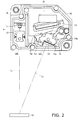
- FIG. 2 is a plan view from the direction of the arrow II in FIG. 1 , showing a case in which a cover 33 of the optical displacement sensor 10 shown in FIG. 1 is removed.
- FIG. 2 also shows an object to be measured 16.
- the optical displacement sensor 10 measures the displacement of the object to be measured 16.
- a projection module 9 for emitting light in a desired beam shape to the object to be measured 16, a light-receiving element 13 for receiving reflected light from the object to be measured 16, the reflected light being formed by light from the projection module 9, and a light-receiving lens 14 positioned between the object to be measured 16 and the light-receiving element 13 are provided inside a substantially rectangular housing 30.
- the projection module 9 includes a light source 11 for emitting light, and a projection lens 12 positioned between the object to be measured 16 and the light source 11.
- the projection module 9, the light-receiving element 13, and the light-receiving lens 14 constitute a predetermined optical system.
- the optical axis of the projection module 9 i.e., the projection axis L 1 , along which the light rays emitted by the projection module 9 travel, and the optical axis, i.e., the light-receiving axis L 2 , of the light-receiving lens 14 for receiving the reflected light from the object to be measured 16
- the housing 30 has a bottom surface 31 disposed at the bottom on which the members constituting the optical system of the optical displacement sensor 10 are fixed, and openings 32a, 32b, and includes a side wall 32 disposed so as to surround the peripheral edge of the bottom surface 31, and a cover 33 disposed opposite the bottom surface 31.
- the bottom surface 31 is flat, and the light source 11 and other components are fixed thereon.
- the side wall 32 is configured so as to have a connecting part (not shown) to which a cable or the like can be connected.
- the opening 32a is provided opposite the light-receiving lens 14, and the opening 32b is provided opposite the projection lens 12.
- FIG. 3 is a perspective view showing the projection lens 12.
- FIG. 4 is a perspective view showing the light-receiving lens 14.
- the light source 11 is a laser diode which emits a laser beam to the object to be measured 16.
- the projection lens 12 includes a lens holder for accommodating a lens, and collects the light emitted from the light source 11 and adjusts the shape of the light from the light source 11 to form a predetermined shape.
- the light-receiving element 13 is a CMOS (Complementary Metal Oxide Semiconductor) sensor in which the reflected light from the object to be measured 16 is received on a light-receiving face.
- CMOS Complementary Metal Oxide Semiconductor
- the light-receiving lens 14 is a single lens having an aspherical surface on which the reflected light is incident, for example, and is accommodated in a lens holder 15.
- the light-receiving lens 14 collects the reflected light from the object to be measured 16 and images the light on the light-receiving face.
- the light-receiving lens 14 is disposed so that the light-receiving axis L 2 passes through the center of the light-receiving lens 14, and the principal face of the light-receiving lens 14 is orthogonal to the light-receiving axis L 2 .
- the lens holder 15 accommodates the light-receiving lens 14 so that the peripheral edge of the light-receiving lens 14 is sealed in four places, for example, the surface of the lens holder 15 adjacent to the bottom surface 31 is flat, and the shape of the lens holder 15 as viewed from the direction of the arrow II is substantially rectangular.
- Pins 15a through 15d are fixed to the bottom surface 31 in four locations around the lens holder 15.
- the four pins 15a through 15d are disposed so as to correspond to the corners of the substantially rectangular shape of the lens holder 15, and are positioning members for when the lens holder 15 is moved.
- the optical displacement sensor 10 when a laser beam is emitted from the light source 11 of the projection module 9, the emitted light reaches the object to be measured 16 via the opening 32b of the side wall 32 and is reflected by the object to be measured 16.
- the reflected light from the object to be measured 16 is incident on the light-receiving lens 14 via the opening 32a of the side wall 32, and the light-receiving lens 14 images the reflected light on the light-receiving face.
- the position of the image received when the light is imaged is then detected.
- the optical displacement sensor 10 thereby measures the displacement of the object to be measured 16 in the direction of the projection axis L 1 .
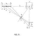
- FIG. 5 is a schematic view showing the optical displacement sensor 10.
- the optical displacement sensor 10 has a predetermined measurement range W 1 in which the displacement of the object to be measured 16 can be measured, as shown in FIG. 5 .
- This predetermined measurement range W 1 indicates the reflection position 16a of light reflected by the object to be measured 16, and is the range from a first position P N1 near the light source 11 on the projection axis L 1 to a second position P F1 , distant from the light source 11.
- the reflection position 16a of the light reflected by the object to be measured 16 has a width in the predetermined measurement range W 1 on the projection axis L 1 .
- the object to be measured 16' at the first position P N1 and the object to be measured 16" at the second position P F1 are indicated by dotted lines in FIG. 5
- the reflection position 16a of light, which is the predetermined measurement range W 1 is indicated by a heavy line.
- the predetermined measurement range W 1 is 20 to 30 mm, for example.
- a light-receiving face 13a of the light-receiving element 13 has a predetermined width W 2 , corresponding to the predetermined measurement range W 1 , from a position P N2 near the light source 11 to a position P F2 distant from the light source 11.
- the configuration of the optical displacement sensor 10 is adjusted so that a predetermined optical system satisfies the Scheimpflug condition, i.e., so that lines extending from the reflection position 16a (projection axis L 1 ) for the object to be measured 16, a principal face 14a of the light-receiving lens 14, and the light-receiving face 13a of the light-receiving element 13 intersect at a single point S 1 .
- focus is achieved on the light-receiving face 13a during imaging, irrespective of the position at which the light is reflected in the measurement range W 1 .
- the optical displacement sensor 10 thus measures the displacement of the object to be measured 16 in the measurement range W 1 .
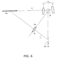
- FIG. 6 is a view showing a case in which the Scheimpflug condition is not met in the schematic view of FIG. 5 .
- FIG. 7 is a view showing the procedure for adjusting the position of the light-receiving lens 14 so that the Scheimpflug condition is met in the schematic view of FIG. 6 .
- the position-adjusted light-receiving lens 14, the principal face 14a of the light-receiving lens 14, and the light-receiving axis L 2 ' are indicated by dot-dash lines in FIG. 7 .
- the line extending from the reflection position 16a of the object to be measured 16 on the projection axis L 1 ' does not intersect at a single point with the lines extending from the principal face 14a of the light-receiving lens 14 and the light-receiving face 13a of the light-receiving portion 13. The method of adjustment for such a case will be described.
- the light source 11, the projection lens 12, the light-receiving element 13, and the light-receiving lens 14 are arranged in advance as shown in FIG. 6 .
- the light source 11, the projection lens 12, and the light-receiving element 13, for example, are mounted on the bottom surface 31 of the housing 30 in advance.
- This mounting step is the first attachment step.
- the position of the light-receiving lens 14 is then moved. Specifically, with the light-receiving lens 14 accommodated in the lens holder 15, the lens holder 15 is pushed against the bottom surface 31 by an arm or the like. In this state, the light-receiving lens 14 is slid in the Z 1 direction (direction of the light-receiving axis L 2 ) and the X 1 direction (direction parallel to the bottom surface 31 and perpendicular to the direction of the light-receiving axis L 2 ) in FIG. 7 . Sliding means slipping on the bottom surface 31.
- the bottom surface 31 constitutes a reference surface as a reference for moving the light-receiving lens 14, and the light-receiving lens 14 is moved forward, backward, left, and right in two axes with the reference surface as a reference.
- the range of movement of the lens holder 15 at this time is restricted by the pins 15 a through 15d.
- Adjustment is thus performed by moving the light-receiving lens 14 so that the Scheimpflug condition is met.
- the light-receiving axis L 2 is adjusted in the Z 1 direction (direction of the light-receiving axis L 2 ) and the X 1 direction (direction parallel to the bottom surface 31 and perpendicular to the direction of the light-receiving axis L 2 ).
- the step of moving the light-receiving lens 14 is the light-receiving lens movement step.
- the lens holder 15 is fixed to the bottom surface 31 at the position.
- An ultraviolet-curing adhesive, a screw, or the like is used for this fixing. As shown in FIG.
- the step of fixing the light-receiving lens 14 to the bottom surface 31 is the second attachment step.
- the predetermined optical system can be adjusted to meet the Scheimpflug condition by moving only the light-receiving lens 14. Specifically, only a single member need be adjusted. The amount of labor required for adjustment can thereby be kept from increasing, the optical displacement sensor 10 can be reduced in size, and the size of the facility for manufacturing the optical displacement sensor 10 can also be reduced. As a result, adjustment can be easily performed.
- the adjustment is accomplished merely by sliding the lens holder 15 on the bottom surface 31, the light-receiving lens 14 being accommodated in the lens holder, there is no need to provide another mechanism for adjustment, and the adjustment can be performed by a simple method.
- the predetermined optical system can be adjusted to meet the Scheimpflug condition by moving only the light-receiving lens 14. Specifically, only a single member need be adjusted. The amount of labor required for adjustment can thereby be kept from increasing, the optical displacement sensor 10 can be reduced in size, and the size of the facility for manufacturing the optical displacement sensor 10 can also be reduced. As a result, adjustment can be easily performed.
- FIG. 8 is a view showing the procedure for adjusting the position of the projection lens 12 so that the Scheimpflug condition is met in the schematic view of FIG. 6 .
- the position-adjusted projection lens 12 and the projection axis L 1 " are indicated by two-dot chain lines in FIG. 8 .
- the light source 11, the projection lens 12, the light-receiving element 13, and the light-receiving lens 14 are arranged in advance as shown in FIG. 6 .
- the light source 11 and the light-receiving element 13, for example, are mounted on the bottom surface 31 of the housing 30 in advance.
- the position of the projection lens 12 is first moved. Specifically, by holding the lens holder, in which the projection lens 12 is accommodated, with an arm or the like at the top part of the cover 33 side of the bottom surface 31, the projection lens 12 is moved in the Z 2 direction (direction of the projection axis L 1 ), the X 2 direction (direction parallel to the bottom surface 31 and perpendicular to the projection axis L 1 ), and the Y 2 direction (direction perpendicular to the bottom surface 31 and perpendicular to the projection axis L 1 ) in FIG. 8 .
- the projection lens 12 in a state of separation from the bottom surface 31 is moved along the triaxial directions including the forward-backward, left-right, and up-down axes.
- the projection axis L 1 is adjusted in the Z 2 direction (direction of the projection axis L 1 ), the X 2 direction (direction parallel to the bottom surface 31 and perpendicular to the projection axis L 1 ), and the Y 2 direction (direction perpendicular to the bottom surface 31 and perpendicular to the projection axis L 1 ).
- the projection lens 12 is then fixed in the position to which the projection lens is moved, and after the projection lens 12 is thus fixed, the light-receiving lens 14 is fixed to the bottom surface 31 in the same manner as in the light-receiving lens movement step and the second attachment step described above.
- the attachment positions of the projection lens 12 and the light-receiving lens 14 are thus adjusted so that the Scheimpflug condition is met.
- the inclination of the projection axis L 1 ' can be suppressed in a case in which the Scheimpflug condition is not met as components are arranged at an angle to the bottom surface 31 due to such factors as variation in the shape of the components constituting the projection module 9, for example.
- the position of the light-receiving lens 14 can also be adjusted with a suppressed movement.
- the light-receiving element 13 is a CMOS sensor in the embodiment described above, but this configuration is not limiting, and the light-receiving element 13 may also be a CCD (Charge Coupled Device) sensor.
- CCD Charge Coupled Device
- pins 15a through 15d are provided around the lens holder 15 and the movement range of the lens holder 15 is restricted by the pins 15a through 15d, but this configuration is not limiting, and a configuration may be adopted in which pins 15a through 15d in particular are not provided, and the movement range of the lens holder 15 is not restricted.
- the above embodiment describes an optical displacement sensor 10 being adjusted so that the Scheimpflug condition is met, but this configuration is not limiting, and the present invention can also be applied to adjusting an optical system. Specifically, only the light-receiving lens 14 need be adjusted to adjust the optical system.
- the present invention is effective for use in manufacturing an optical displacement sensor.
Landscapes
- Physics & Mathematics (AREA)
- Engineering & Computer Science (AREA)
- General Physics & Mathematics (AREA)
- Electromagnetism (AREA)
- Radar, Positioning & Navigation (AREA)
- Remote Sensing (AREA)
- Computer Networks & Wireless Communication (AREA)
- Measurement Of Optical Distance (AREA)
- Length Measuring Devices By Optical Means (AREA)
- Optical Radar Systems And Details Thereof (AREA)
Abstract
Description
- The present invention relates to a method for adjusting an optical displacement sensor and a method for manufacturing an optical displacement sensor, and particularly relates to a method for adjusting an optical displacement sensor for measuring the displacement of an object to be measured by using a triangulation principle, and a method for manufacturing an optical displacement sensor.
- A conventional optical displacement sensor is disclosed in Japanese Laid-open Patent Publication No.
2008-145160 FIG. 9 is a view showing the conventionaloptical displacement sensor 100 disclosed in Patent Citation 1. As shown inFIG. 9 , theoptical displacement sensor 100 is provided with aprojection module 101 which includes a laser diode 10 a for radiating light to an object to be measured 106, and aprojection lens 101b for collecting light from thelaser diode 101a; aCCD 103 for receiving the reflected light on a light-receivingface 103a when the light from theprojection module 101 is reflected by the object to be measured 106; and a light-receivinglens 104 for imaging the reflected light on the light-receivingface 103a of theCCD 103. - When light is radiated toward the object to be measured 106 from the
laser diode 101a, the radiated light is reflected by the object to be measured 106, and the reflected light is received by the light-receivingface 103a of theCCD 103 via the light-receivinglens 104, and theoptical displacement sensor 100 thereby measures the displacement of the object to be measured 106 on the basis of the position of an image formed by the received light. - (Patent Citation 1) Japanese Laid-open Patent Publication No.
2008-145160 - The arrangement of the
projection module 101, theCCD 103, and the light-receivinglens 104 is adjusted so that the Scheimpflug condition is met. Specifically, the light-receivingface 103a of theCCD 103 has a predetermined width W2, and the reflection position of an object to be measured 106 in the range in which reflected light can be received by the light-receivingface 103a has a predetermined width W1 on the optical axis of theprojection module 101, i.e., the projection axis L1. The arrangement of the abovementioned components is adjusted so that lines extending from the reflection position in the predetermined width W1, the light-receivingface 103a, and aprincipal face 104a of the light-receivinglens 104 intersect at a single point D, i.e., so that the Scheimpflug condition is met. By this adjustment, focus is achieved on the light-receivingface 103a during imaging, irrespective of the position at which the light is reflected in the predetermined width W1. The light-receivinglens 104 is considered to be a thin lens in this description. - In the adjustment according to
Patent Citation 1, the light-receivinglens 104 is shifted along the optical axis of the light-receivinglens 104, i.e., in the direction of the light-receiving axis L2, as indicated by the arrow A inFIG. 9 , and theCCD 103 is slid and rotated as indicated by the arrows B and C inFIG. 9 . Specifically, two members, the light-receivinglens 104 and theCCD 103, are adjusted. - However, with this adjustment method, for example, in the case that the
CCD 103 is adjusted after the light-receivinglens 104 is adjusted, the light-receivinglens 104 must sometimes be readjusted when there is any error in the adjustment of theCCD 103, and adjustment is troublesome to perform. A larger amount of labor may then be required to perform the adjustment. Individual mechanisms must also be provided for adjustment, thus increasing the size of theoptical displacement sensor 100 and possibly leading to increased size of the facility for manufacturing theoptical displacement sensor 100. - A first object of the present invention is to provide a method for adjusting an optical displacement sensor whereby the optical system of an optical displacement sensor can be easily adjusted.
- A second object of the present invention is to provide a method for manufacturing an optical displacement sensor in which the optical system of the optical displacement sensor can be easily adjusted.
- A method for adjusting an optical displacement sensor according to a first aspect of the present invention relates to a method for adjusting an optical displacement sensor having a predetermined optical system. The predetermined optical system has a projection module configured to project light onto an object to be measured, a light-receiving element configured to receive reflected light reflected by the object to be measured of light projected from the projection module, and a light-receiving lens configured to image the reflected light onto the light-receiving element, the light-receiving lens being positioned between the object to be measured and the light-receiving element. The adjustment method performs an adjustment by moving only the light-receiving lens in a direction of an optical axis of the light-receiving lens and in a direction perpendicular to the direction of the optical axis of the light-receiving lens.
- The predetermined optical system can thereby be adjusted by moving only the light-receiving lens. Specifically, only a single member need be adjusted. The amount of labor required for adjustment can thereby be kept from increasing, the optical displacement sensor can be reduced in size, and the size of the facility for manufacturing the optical displacement sensor can also be reduced. As a result, adjustment can be easily performed.
- In an embodiment, the adjustment method adjusts the predetermined optical system so that the Scheimpflug condition is met. The predetermined optical system can thereby be adjusted to meet the Scheimpflug condition by moving only the light-receiving lens.
- Preferably, the projection module, the light-receiving element, and the light-receiving lens are arranged on a reference surface constituting a housing of the optical displacement sensor, and the adjustment method performs the adjustment by sliding the light-receiving lens over the reference surface. This obviates the need to provide another mechanism for adjustment, and enables adjustment by a simple method.
- Preferably, the projection module has a light source configured to emit light, and a projection lens configured to adjust light from the light source to a predetermined shape, and the adjustment method performs the adjustment by moving the projection lens in a direction of an optical axis of the projection lens, in a direction perpendicular to the direction of the optical axis of the projection lens and parallel to the reference surface, and in a direction perpendicular to the direction of the optical axis of the projection lens and perpendicular to the reference surface. Through this configuration, the inclination of the optical axis of the projection module can be adjusted in a case in which the Scheimpflug condition is not met as components are arranged at an angle to the reference surface due to such factors as variation in the shape of the components constituting the projection module, for example.
- A method for manufacturing an optical displacement sensor according to a second aspect of the present invention relates to a method for manufacturing an optical displacement sensor having a projection module configured to project light onto an object to be measured, a light-receiving element configured to receive reflected light projected by the projection module and reflected by the object to be measured, and a light-receiving lens configured to image the reflected light onto the light-receiving element, the light-receiving lens being positioned between the object to be measured and the light-receiving element. The manufacturing method comprises a first attachment step of mounting the projection module and the light-receiving element to a reference surface constituting a housing of the optical displacement sensor; a light-receiving lens movement step of moving the light-receiving lens in a direction of an optical axis of the light-receiving lens and in a direction perpendicular to the direction of the optical axis of the light-receiving lens, the reference surface used as a reference; and a second attachment step of mounting the light-receiving lens to the reference surface at a position to which the light-receiving lens is moved in the light-receiving lens movement step.
- The predetermined optical system can thereby be adjusted by moving only the light-receiving lens during manufacturing of the optical displacement sensor. Specifically, only a single member need be adjusted. The amount of labor required for adjustment can thereby be kept from increasing, the optical displacement sensor can be reduced in size, and the size of the facility for manufacturing the optical displacement sensor can also be reduced. As a result, adjustment can be easily performed.
- The method for adjusting an optical displacement sensor according to the present invention enables a predetermined optical system to be adjusted by moving only the light-receiving lens. Specifically, only a single member need be adjusted. The amount of labor required for adjustment can thereby be kept from increasing, the optical displacement sensor can be reduced in size, and the size of the facility for manufacturing the optical displacement sensor can also be reduced. As a result, adjustment can be easily performed.
- The method for manufacturing an optical displacement sensor according to the present invention enables a predetermined optical system to be adjusted by moving only the light-receiving lens. Specifically, only a single member need be adjusted. The amount of labor required for adjustment can thereby be kept from increasing, the optical displacement sensor can be reduced in size, and the size of the facility for manufacturing the optical displacement sensor can also be reduced. As a result, adjustment can be easily performed.
-
-
FIG. 1 is a perspective view showing the outside of the optical displacement sensor. -
FIG. 2 is a plan view from the direction of the arrow II inFIG. 1 , showing a case in which the cover of the optical displacement sensor shown inFIG. 1 is removed. -
FIG. 3 is a perspective view showing the projection lens. -
FIG. 4 is a perspective view showing the light-receiving lens. -
FIG. 5 is a schematic view showing the optical displacement sensor. -
FIG. 6 is a view showing a case in which the Scheimpflug condition is not met in the schematic view ofFIG. 5 . -
FIG. 7 is a view showing the procedure for adjusting the position of the light-receiving lens so that the Scheimpflug condition is met in the schematic view ofFIG. 6 . -
FIG. 8 is a view showing the procedure for adjusting the position of the projection lens so that the Scheimpflug condition is met in the schematic view ofFIG. 6 . -
FIG. 9 is a view showing the conventional optical displacement sensor disclosed in Patent Citation 1. - The method for adjusting an optical displacement sensor according to an embodiment of the present invention will be described with reference to the drawings.
FIG. 1 is a perspective view showing the outside of theoptical displacement sensor 10.FIG. 2 is a plan view from the direction of the arrow II inFIG. 1 , showing a case in which acover 33 of theoptical displacement sensor 10 shown inFIG. 1 is removed. In addition to the plan view of theoptical displacement sensor 10,FIG. 2 also shows an object to be measured 16. As shown inFIGS. 1 and2 , theoptical displacement sensor 10 measures the displacement of the object to be measured 16. In theoptical displacement sensor 10, aprojection module 9 for emitting light in a desired beam shape to the object to be measured 16, a light-receivingelement 13 for receiving reflected light from the object to be measured 16, the reflected light being formed by light from theprojection module 9, and a light-receivinglens 14 positioned between the object to be measured 16 and the light-receivingelement 13 are provided inside a substantiallyrectangular housing 30. Theprojection module 9 includes alight source 11 for emitting light, and aprojection lens 12 positioned between the object to be measured 16 and thelight source 11. Theprojection module 9, the light-receivingelement 13, and the light-receivinglens 14 constitute a predetermined optical system. The three-dot chain lines inFIG. 2 indicate the optical axis of theprojection module 9, i.e., the projection axis L1, along which the light rays emitted by theprojection module 9 travel, and the optical axis, i.e., the light-receiving axis L2, of the light-receivinglens 14 for receiving the reflected light from the object to be measured 16 - The
housing 30 has abottom surface 31 disposed at the bottom on which the members constituting the optical system of theoptical displacement sensor 10 are fixed, andopenings side wall 32 disposed so as to surround the peripheral edge of thebottom surface 31, and acover 33 disposed opposite thebottom surface 31. Thebottom surface 31 is flat, and thelight source 11 and other components are fixed thereon. Theside wall 32 is configured so as to have a connecting part (not shown) to which a cable or the like can be connected. Theopening 32a is provided opposite the light-receivinglens 14, and theopening 32b is provided opposite theprojection lens 12. -
FIG. 3 is a perspective view showing theprojection lens 12.FIG. 4 is a perspective view showing the light-receivinglens 14. As shown inFIGS. 1 through 4 , thelight source 11 is a laser diode which emits a laser beam to the object to be measured 16. Theprojection lens 12 includes a lens holder for accommodating a lens, and collects the light emitted from thelight source 11 and adjusts the shape of the light from thelight source 11 to form a predetermined shape. The light-receivingelement 13 is a CMOS (Complementary Metal Oxide Semiconductor) sensor in which the reflected light from the object to be measured 16 is received on a light-receiving face. A plurality of light-receiving elements is arranged in a line on the light-receiving face. The light-receivinglens 14 is a single lens having an aspherical surface on which the reflected light is incident, for example, and is accommodated in alens holder 15. The light-receivinglens 14 collects the reflected light from the object to be measured 16 and images the light on the light-receiving face. The light-receivinglens 14 is disposed so that the light-receiving axis L2 passes through the center of the light-receivinglens 14, and the principal face of the light-receivinglens 14 is orthogonal to the light-receiving axis L2. - The
lens holder 15 accommodates the light-receivinglens 14 so that the peripheral edge of the light-receivinglens 14 is sealed in four places, for example, the surface of thelens holder 15 adjacent to thebottom surface 31 is flat, and the shape of thelens holder 15 as viewed from the direction of the arrow II is substantially rectangular.Pins 15a through 15d are fixed to thebottom surface 31 in four locations around thelens holder 15. The fourpins 15a through 15d are disposed so as to correspond to the corners of the substantially rectangular shape of thelens holder 15, and are positioning members for when thelens holder 15 is moved. - In the
optical displacement sensor 10, when a laser beam is emitted from thelight source 11 of theprojection module 9, the emitted light reaches the object to be measured 16 via theopening 32b of theside wall 32 and is reflected by the object to be measured 16. The reflected light from the object to be measured 16 is incident on the light-receivinglens 14 via theopening 32a of theside wall 32, and the light-receivinglens 14 images the reflected light on the light-receiving face. The position of the image received when the light is imaged is then detected. Theoptical displacement sensor 10 thereby measures the displacement of the object to be measured 16 in the direction of the projection axis L1. - In this
optical displacement sensor 10, the arrangement of theprojection module 9, the light-receivingelement 13, and the light-receivinglens 14 is adjusted so as to satisfy the Scheimpflug condition.FIG. 5 is a schematic view showing theoptical displacement sensor 10. Specifically, theoptical displacement sensor 10 has a predetermined measurement range W1 in which the displacement of the object to be measured 16 can be measured, as shown inFIG. 5 . This predetermined measurement range W1 indicates thereflection position 16a of light reflected by the object to be measured 16, and is the range from a first position PN1 near thelight source 11 on the projection axis L1 to a second position PF1, distant from thelight source 11. Specifically, thereflection position 16a of the light reflected by the object to be measured 16 has a width in the predetermined measurement range W1 on the projection axis L1. The object to be measured 16' at the first position PN1 and the object to be measured 16" at the second position PF1 are indicated by dotted lines inFIG. 5 , and thereflection position 16a of light, which is the predetermined measurement range W1, is indicated by a heavy line. The predetermined measurement range W1 is 20 to 30 mm, for example. A light-receivingface 13a of the light-receivingelement 13 has a predetermined width W2, corresponding to the predetermined measurement range W1, from a position PN2 near thelight source 11 to a position PF2 distant from thelight source 11. - The configuration of the
optical displacement sensor 10 is adjusted so that a predetermined optical system satisfies the Scheimpflug condition, i.e., so that lines extending from thereflection position 16a (projection axis L1) for the object to be measured 16, aprincipal face 14a of the light-receivinglens 14, and the light-receivingface 13a of the light-receivingelement 13 intersect at a single point S1. By this adjustment in theoptical displacement sensor 10, focus is achieved on the light-receivingface 13a during imaging, irrespective of the position at which the light is reflected in the measurement range W1. Theoptical displacement sensor 10 thus measures the displacement of the object to be measured 16 in the measurement range W1. - The specific method of adjustment to meet the Scheimpflug condition will next be described.
FIG. 6 is a view showing a case in which the Scheimpflug condition is not met in the schematic view ofFIG. 5 .FIG. 7 is a view showing the procedure for adjusting the position of the light-receivinglens 14 so that the Scheimpflug condition is met in the schematic view ofFIG. 6 . The position-adjusted light-receivinglens 14, theprincipal face 14a of the light-receivinglens 14, and the light-receiving axis L2' are indicated by dot-dash lines inFIG. 7 . - As shown in
FIG. 6 , since the attachment position of thelight source 11 is misaligned, the line extending from thereflection position 16a of the object to be measured 16 on the projection axis L1' does not intersect at a single point with the lines extending from theprincipal face 14a of the light-receivinglens 14 and the light-receivingface 13a of the light-receivingportion 13. The method of adjustment for such a case will be described. - First, the
light source 11, theprojection lens 12, the light-receivingelement 13, and the light-receivinglens 14 are arranged in advance as shown inFIG. 6 . At this time, thelight source 11, theprojection lens 12, and the light-receivingelement 13, for example, are mounted on thebottom surface 31 of thehousing 30 in advance. This mounting step is the first attachment step. - The position of the light-receiving
lens 14 is then moved. Specifically, with the light-receivinglens 14 accommodated in thelens holder 15, thelens holder 15 is pushed against thebottom surface 31 by an arm or the like. In this state, the light-receivinglens 14 is slid in the Z1 direction (direction of the light-receiving axis L2) and the X1 direction (direction parallel to thebottom surface 31 and perpendicular to the direction of the light-receiving axis L2) inFIG. 7 . Sliding means slipping on thebottom surface 31. Specifically, thebottom surface 31 constitutes a reference surface as a reference for moving the light-receivinglens 14, and the light-receivinglens 14 is moved forward, backward, left, and right in two axes with the reference surface as a reference. The range of movement of thelens holder 15 at this time is restricted by thepins 15 a through 15d. - Adjustment is thus performed by moving the light-receiving
lens 14 so that the Scheimpflug condition is met. Specifically, the light-receiving axis L2 is adjusted in the Z1 direction (direction of the light-receiving axis L2) and the X1 direction (direction parallel to thebottom surface 31 and perpendicular to the direction of the light-receiving axis L2). The step of moving the light-receivinglens 14 is the light-receiving lens movement step. - When the light-receiving
lens 14 reaches the position at which the Scheimpflug condition is met, i.e., the position at which lines extending from thereflection position 16a of the object to be measured 16, theprincipal face 14a of the light-receivinglens 14, and the light-receivingface 13a of the light-receivingelement 13 intersect at a single point, thelens holder 15 is fixed to thebottom surface 31 at the position. An ultraviolet-curing adhesive, a screw, or the like is used for this fixing. As shown inFIG. 7 , the line extending from thereflection position 16a of the object to be measured 16 and the one-dot chain line extending from theprincipal face 14a of the position-adjusted light-receivinglens 14 and the line extending from the light-receivingface 13a of the light-receivingelement 13 intersect at a single point S2. The step of fixing the light-receivinglens 14 to thebottom surface 31 is the second attachment step. - By the method for adjusting the
optical displacement sensor 10, the predetermined optical system can be adjusted to meet the Scheimpflug condition by moving only the light-receivinglens 14. Specifically, only a single member need be adjusted. The amount of labor required for adjustment can thereby be kept from increasing, theoptical displacement sensor 10 can be reduced in size, and the size of the facility for manufacturing theoptical displacement sensor 10 can also be reduced. As a result, adjustment can be easily performed. - Since the adjustment is accomplished merely by sliding the
lens holder 15 on thebottom surface 31, the light-receivinglens 14 being accommodated in the lens holder, there is no need to provide another mechanism for adjustment, and the adjustment can be performed by a simple method. - By the method for manufacturing the
optical displacement sensor 10, the predetermined optical system can be adjusted to meet the Scheimpflug condition by moving only the light-receivinglens 14. Specifically, only a single member need be adjusted. The amount of labor required for adjustment can thereby be kept from increasing, theoptical displacement sensor 10 can be reduced in size, and the size of the facility for manufacturing theoptical displacement sensor 10 can also be reduced. As a result, adjustment can be easily performed. - Another method for adjusting to meet the Scheimpflug will next be described.
FIG. 8 is a view showing the procedure for adjusting the position of theprojection lens 12 so that the Scheimpflug condition is met in the schematic view ofFIG. 6 . The position-adjustedprojection lens 12 and the projection axis L1" are indicated by two-dot chain lines inFIG. 8 . - The adjustment method for the state shown in
FIG. 6 will again be described. - First, the
light source 11, theprojection lens 12, the light-receivingelement 13, and the light-receivinglens 14 are arranged in advance as shown inFIG. 6 . At this time, thelight source 11 and the light-receivingelement 13, for example, are mounted on thebottom surface 31 of thehousing 30 in advance. - Here, the position of the
projection lens 12 is first moved. Specifically, by holding the lens holder, in which theprojection lens 12 is accommodated, with an arm or the like at the top part of thecover 33 side of thebottom surface 31, theprojection lens 12 is moved in the Z2 direction (direction of the projection axis L1), the X2 direction (direction parallel to thebottom surface 31 and perpendicular to the projection axis L1), and the Y2 direction (direction perpendicular to thebottom surface 31 and perpendicular to the projection axis L1) inFIG. 8 . In other words, theprojection lens 12 in a state of separation from thebottom surface 31 is moved along the triaxial directions including the forward-backward, left-right, and up-down axes. - By moving the
projection lens 12 in this manner, the projection axis L1 is adjusted in the Z2 direction (direction of the projection axis L1), the X2 direction (direction parallel to thebottom surface 31 and perpendicular to the projection axis L1), and the Y2 direction (direction perpendicular to thebottom surface 31 and perpendicular to the projection axis L1). - The
projection lens 12 is then fixed in the position to which the projection lens is moved, and after theprojection lens 12 is thus fixed, the light-receivinglens 14 is fixed to thebottom surface 31 in the same manner as in the light-receiving lens movement step and the second attachment step described above. - The attachment positions of the
projection lens 12 and the light-receivinglens 14 are thus adjusted so that the Scheimpflug condition is met. Through this configuration, the inclination of the projection axis L1' can be suppressed in a case in which the Scheimpflug condition is not met as components are arranged at an angle to thebottom surface 31 due to such factors as variation in the shape of the components constituting theprojection module 9, for example. The position of the light-receivinglens 14 can also be adjusted with a suppressed movement. - The light-receiving
element 13 is a CMOS sensor in the embodiment described above, but this configuration is not limiting, and the light-receivingelement 13 may also be a CCD (Charge Coupled Device) sensor. - An example is described in the above embodiment in which the light-receiving
lens 14 is moved by sliding on thebottom surface 31 in S12, but this configuration is not limiting, and grooves or the like extending in the Z1 direction and X1 direction may be provided in thebottom surface 31, and the light-receivinglens 14 may be moved along the grooves, for example. - An example is described in the above embodiment in which pins 15a through 15d are provided around the
lens holder 15 and the movement range of thelens holder 15 is restricted by thepins 15a through 15d, but this configuration is not limiting, and a configuration may be adopted in which pins 15a through 15d in particular are not provided, and the movement range of thelens holder 15 is not restricted. - An example is described in the above embodiment in which the movement of the light-receiving
lens 14 is restricted by thepins 15a through 15d, but movement of theprojection lens 12 as well may be restricted by attaching a pin or the like to thebottom surface 31 in advance in the same manner. - The above embodiment describes an
optical displacement sensor 10 being adjusted so that the Scheimpflug condition is met, but this configuration is not limiting, and the present invention can also be applied to adjusting an optical system. Specifically, only the light-receivinglens 14 need be adjusted to adjust the optical system. - An example is described in the above embodiment in which the light-receiving
lens 14 is moved with thebottom surface 31 as a reference surface, but this configuration is not limiting, and theside wall 32, for example, or another surface may be used as a reference surface for movement. - An embodiment of the invention was described above with reference to the drawings, but the present invention is not limited to the embodiment shown in the drawings. Various revisions and/or modifications within a scope the same as or equivalent to that of the present invention may be made to the embodiment shown in the drawings
- The present invention is effective for use in manufacturing an optical displacement sensor.
-
- 9 projection module
- 10 optical displacement sensor
- 11 light source
- 12 projection lens
- 13 light-receiving element
- 13 a light-receiving face
- 14 light-receiving lens
- 14a principal face
- 15 lens holder
- 15a-15d pins
- 16 measured object
- 16a reflection position
- 30 housing
- 31 bottom surface
- 32 side wall
- 32a, 32b openings
- 33 cover
Claims (5)
- A method for adjusting an optical displacement sensor including a predetermined optical system, the predetermined optical system having a projection module configured to project light onto an object to be measured, a light-receiving element configured to receive reflected light reflected by the object to be measured of light projected from the projection module, and a light-receiving lens configured to image the reflected light onto the light-receiving element, the light-receiving lens being positioned between the object to be measured and the light-receiving element;
the method comprising
adjusting by moving only the light-receiving lens in a direction of an optical axis of the light-receiving lens and in a direction perpendicular to the direction of the optical axis of the light-receiving lens. - The method for adjusting the optical displacement sensor according to claim 1, wherein adjusting includes adjusting the predetermined optical system so that the Scheimpflug condition is met.
- The method for adjusting the optical displacement sensor according to claim 1 or 2, wherein
the projection module, the light-receiving element, and the light-receiving lens are arranged on a reference surface constituting a housing of the optical displacement sensor, and
adjusting is performed by sliding the light-receiving lens over the referene surface. - The method for adjusting the optical displacement sensor according to claim 3, wherein
the projection module has a light source configured to emit light, and a projection lens configured to adjust light from the light source to a predetermined shape; and
the method further comprising
adjusting by moving the projection lens in a direction of an optical axis of the projection lens, in a direction perpendicular to the direction of the optical axis of the projection lens and parallel to the reference surface, and in a direction perpendicular to the direction of the optical axis of the projection lens and perpendicular to the reference surface. - A method for manufacturing an optical displacement sensor having a projection module configured to project light onto an object to be measured, a light-receiving element configured to receive reflected light reflected by the object to be measured of light projected from the projection module, and a light-receiving lens configured to image the reflected light onto the light-receiving element, the light-receiving lens being positioned between the object to be measured and the light-receiving element, the method comprising:a first attachment step of mounting the projection module and the light-receiving element to a reference surface constituting a housing of the optical displacement sensor;a light-receiving lens movement step of moving the light-receiving lens in a direction of an optical axis of the light-receiving lens and in a direction perpendicular to the direction of the optical axis of the light-receiving lens, the reference surface used as a reference; anda second attachment step of mounting the light-receiving lens to the reference surface at a position to which the light-receiving lens is moved in the light-receiving lens movement step.
Applications Claiming Priority (2)
| Application Number | Priority Date | Filing Date | Title |
|---|---|---|---|
| JP2010222238A JP5418458B2 (en) | 2010-09-30 | 2010-09-30 | Method for adjusting optical displacement sensor, method for manufacturing optical displacement sensor, and optical displacement sensor |
| PCT/JP2011/057137 WO2012042944A1 (en) | 2010-09-30 | 2011-03-24 | Method for adjusting optical displacement sensor and method for manufacturing optical displacement sensor |
Publications (3)
| Publication Number | Publication Date |
|---|---|
| EP2538172A1 true EP2538172A1 (en) | 2012-12-26 |
| EP2538172A4 EP2538172A4 (en) | 2014-12-17 |
| EP2538172B1 EP2538172B1 (en) | 2019-09-04 |
Family
ID=45892427
Family Applications (1)
| Application Number | Title | Priority Date | Filing Date |
|---|---|---|---|
| EP11828506.3A Active EP2538172B1 (en) | 2010-09-30 | 2011-03-24 | Method for adjusting optical displacement sensor and method for manufacturing optical displacement sensor |
Country Status (4)
| Country | Link |
|---|---|
| EP (1) | EP2538172B1 (en) |
| JP (1) | JP5418458B2 (en) |
| CN (1) | CN102834692B (en) |
| WO (1) | WO2012042944A1 (en) |
Cited By (3)
| Publication number | Priority date | Publication date | Assignee | Title |
|---|---|---|---|---|
| US20150285743A1 (en) * | 2014-04-07 | 2015-10-08 | Seagate Technology Llc | Features maps of articles with polarized light |
| US9448106B2 (en) | 2012-10-30 | 2016-09-20 | Omron Corporation | Optical sensor |
| US11226196B2 (en) | 2017-07-31 | 2022-01-18 | Nidek Co., Ltd. | Eyeglass frame shape measurement device and lens processing device |
Families Citing this family (4)
| Publication number | Priority date | Publication date | Assignee | Title |
|---|---|---|---|---|
| CN109444913A (en) * | 2018-12-28 | 2019-03-08 | 广州市合熠电子科技有限公司 | A kind of digital intelligent miniature laser displacement sensor and its distance measuring method |
| JP7478084B2 (en) | 2020-11-20 | 2024-05-02 | 株式会社キーエンス | Optical Measuring Device |
| JP2023161100A (en) * | 2022-04-25 | 2023-11-07 | フェニックス電機株式会社 | optical measurement mechanism |
| US20250076034A1 (en) * | 2023-08-30 | 2025-03-06 | Keyence Corporation | Optical displacement meter |
Family Cites Families (8)
| Publication number | Priority date | Publication date | Assignee | Title |
|---|---|---|---|---|
| US5032023A (en) * | 1990-07-02 | 1991-07-16 | General Electric Company | Optical fiber based sensor for a variable depth range camera |
| JPH06213657A (en) * | 1993-01-20 | 1994-08-05 | Omron Corp | Displacement measuring device with variable measuring distance |
| JPH09257467A (en) * | 1996-03-22 | 1997-10-03 | Omron Corp | Optical displacement measuring device |
| JP3945120B2 (en) * | 2000-03-31 | 2007-07-18 | 松下電工株式会社 | Ranging sensor and adjustment method thereof |
| DE10044432A1 (en) * | 2000-09-08 | 2002-04-04 | Siemens Ag | Device, method and use for the automatic detection of the wear of the contact wires of overhead lines for electrically powered vehicles |
| JP3587303B2 (en) * | 2001-06-26 | 2004-11-10 | オムロン株式会社 | Optical displacement sensor |
| JP2004117161A (en) * | 2002-09-26 | 2004-04-15 | Sharp Corp | Optical displacement sensor |
| JP5072337B2 (en) * | 2006-12-07 | 2012-11-14 | 株式会社キーエンス | Optical displacement sensor and adjustment method thereof |
-
2010
- 2010-09-30 JP JP2010222238A patent/JP5418458B2/en not_active Expired - Fee Related
-
2011
- 2011-03-24 WO PCT/JP2011/057137 patent/WO2012042944A1/en not_active Ceased
- 2011-03-24 EP EP11828506.3A patent/EP2538172B1/en active Active
- 2011-03-24 CN CN201180015365.6A patent/CN102834692B/en not_active Expired - Fee Related
Cited By (5)
| Publication number | Priority date | Publication date | Assignee | Title |
|---|---|---|---|---|
| US9448106B2 (en) | 2012-10-30 | 2016-09-20 | Omron Corporation | Optical sensor |
| US9593980B2 (en) | 2012-10-30 | 2017-03-14 | Omron Corporation | Optical sensor |
| US20150285743A1 (en) * | 2014-04-07 | 2015-10-08 | Seagate Technology Llc | Features maps of articles with polarized light |
| US10152998B2 (en) * | 2014-04-07 | 2018-12-11 | Seagate Technology Llc | Features maps of articles with polarized light |
| US11226196B2 (en) | 2017-07-31 | 2022-01-18 | Nidek Co., Ltd. | Eyeglass frame shape measurement device and lens processing device |
Also Published As
| Publication number | Publication date |
|---|---|
| JP5418458B2 (en) | 2014-02-19 |
| EP2538172A4 (en) | 2014-12-17 |
| JP2012078153A (en) | 2012-04-19 |
| CN102834692B (en) | 2015-02-25 |
| CN102834692A (en) | 2012-12-19 |
| EP2538172B1 (en) | 2019-09-04 |
| WO2012042944A1 (en) | 2012-04-05 |
Similar Documents
| Publication | Publication Date | Title |
|---|---|---|
| EP2538172B1 (en) | Method for adjusting optical displacement sensor and method for manufacturing optical displacement sensor | |
| EP2728378B1 (en) | Optical sensor | |
| JP5549230B2 (en) | Ranging device, ranging module, and imaging device using the same | |
| JP5816836B2 (en) | Optical element holder and stereo image pickup apparatus using the same | |
| US20250362571A1 (en) | Imaging device including an imaging element, a mount, and members | |
| EP2538171A1 (en) | Method for adjusting floodlight beam | |
| JP2023126981A (en) | optical displacement meter | |
| TWI732484B (en) | Camera module manufacturing device and camera module manufacturing method | |
| JP2013050352A (en) | Method of adjusting installation of stereo camera, and stereo camera | |
| EP2538173A1 (en) | Method for arranging photoreceiving lens, and optical displacement sensor | |
| JP6220672B2 (en) | Displacement sensor | |
| US9588260B2 (en) | Microlens substrate and imaging apparatus | |
| US12174445B2 (en) | Camera module manufacturing device | |
| US20250208261A1 (en) | Distance measuring module | |
| US5956534A (en) | Range finder for camera | |
| CN215769015U (en) | Single-lens ranging device, laser radar and mobile robot | |
| WO2022174479A1 (en) | Ranging device, lidar, and mobile robot | |
| JP2021021939A (en) | Imaging unit and vehicle control unit | |
| CN112698462A (en) | Optical member driving device, camera device, and electronic apparatus | |
| JP2018197743A (en) | Photoelectric encoder | |
| JP2589579Y2 (en) | Mounting structure of light emitting element for auto focus | |
| JP7398694B2 (en) | Electronics | |
| JP6504970B2 (en) | Prism dustproof structure of optical equipment | |
| JP2023104675A (en) | Measuring device and manufacturing method of measuring device | |
| WO2022190522A1 (en) | Triangulating displacement sensor |
Legal Events
| Date | Code | Title | Description |
|---|---|---|---|
| PUAI | Public reference made under article 153(3) epc to a published international application that has entered the european phase |
Free format text: ORIGINAL CODE: 0009012 |
|
| 17P | Request for examination filed |
Effective date: 20120921 |
|
| AK | Designated contracting states |
Kind code of ref document: A1 Designated state(s): AL AT BE BG CH CY CZ DE DK EE ES FI FR GB GR HR HU IE IS IT LI LT LU LV MC MK MT NL NO PL PT RO RS SE SI SK SM TR |
|
| DAX | Request for extension of the european patent (deleted) | ||
| A4 | Supplementary search report drawn up and despatched |
Effective date: 20141119 |
|
| RIC1 | Information provided on ipc code assigned before grant |
Ipc: G01S 7/48 20060101ALI20141113BHEP Ipc: G01C 3/06 20060101AFI20141113BHEP Ipc: G01S 7/497 20060101ALI20141113BHEP Ipc: G01S 7/481 20060101ALI20141113BHEP Ipc: G01S 17/48 20060101ALI20141113BHEP Ipc: G01B 11/00 20060101ALI20141113BHEP Ipc: G01B 11/02 20060101ALI20141113BHEP |
|
| STAA | Information on the status of an ep patent application or granted ep patent |
Free format text: STATUS: EXAMINATION IS IN PROGRESS |
|
| 17Q | First examination report despatched |
Effective date: 20170706 |
|
| GRAP | Despatch of communication of intention to grant a patent |
Free format text: ORIGINAL CODE: EPIDOSNIGR1 |
|
| STAA | Information on the status of an ep patent application or granted ep patent |
Free format text: STATUS: GRANT OF PATENT IS INTENDED |
|
| INTG | Intention to grant announced |
Effective date: 20190409 |
|
| GRAS | Grant fee paid |
Free format text: ORIGINAL CODE: EPIDOSNIGR3 |
|
| GRAA | (expected) grant |
Free format text: ORIGINAL CODE: 0009210 |
|
| STAA | Information on the status of an ep patent application or granted ep patent |
Free format text: STATUS: THE PATENT HAS BEEN GRANTED |
|
| AK | Designated contracting states |
Kind code of ref document: B1 Designated state(s): AL AT BE BG CH CY CZ DE DK EE ES FI FR GB GR HR HU IE IS IT LI LT LU LV MC MK MT NL NO PL PT RO RS SE SI SK SM TR |
|
| REG | Reference to a national code |
Ref country code: GB Ref legal event code: FG4D |
|
| REG | Reference to a national code |
Ref country code: CH Ref legal event code: EP |
|
| REG | Reference to a national code |
Ref country code: AT Ref legal event code: REF Ref document number: 1175996 Country of ref document: AT Kind code of ref document: T Effective date: 20190915 |
|
| REG | Reference to a national code |
Ref country code: DE Ref legal event code: R096 Ref document number: 602011061864 Country of ref document: DE Ref country code: IE Ref legal event code: FG4D |
|
| REG | Reference to a national code |
Ref country code: NL Ref legal event code: MP Effective date: 20190904 |
|
| REG | Reference to a national code |
Ref country code: LT Ref legal event code: MG4D |
|
| PG25 | Lapsed in a contracting state [announced via postgrant information from national office to epo] |
Ref country code: BG Free format text: LAPSE BECAUSE OF FAILURE TO SUBMIT A TRANSLATION OF THE DESCRIPTION OR TO PAY THE FEE WITHIN THE PRESCRIBED TIME-LIMIT Effective date: 20191204 Ref country code: SE Free format text: LAPSE BECAUSE OF FAILURE TO SUBMIT A TRANSLATION OF THE DESCRIPTION OR TO PAY THE FEE WITHIN THE PRESCRIBED TIME-LIMIT Effective date: 20190904 Ref country code: HR Free format text: LAPSE BECAUSE OF FAILURE TO SUBMIT A TRANSLATION OF THE DESCRIPTION OR TO PAY THE FEE WITHIN THE PRESCRIBED TIME-LIMIT Effective date: 20190904 Ref country code: NO Free format text: LAPSE BECAUSE OF FAILURE TO SUBMIT A TRANSLATION OF THE DESCRIPTION OR TO PAY THE FEE WITHIN THE PRESCRIBED TIME-LIMIT Effective date: 20191204 Ref country code: FI Free format text: LAPSE BECAUSE OF FAILURE TO SUBMIT A TRANSLATION OF THE DESCRIPTION OR TO PAY THE FEE WITHIN THE PRESCRIBED TIME-LIMIT Effective date: 20190904 Ref country code: LT Free format text: LAPSE BECAUSE OF FAILURE TO SUBMIT A TRANSLATION OF THE DESCRIPTION OR TO PAY THE FEE WITHIN THE PRESCRIBED TIME-LIMIT Effective date: 20190904 |
|
| PG25 | Lapsed in a contracting state [announced via postgrant information from national office to epo] |
Ref country code: GR Free format text: LAPSE BECAUSE OF FAILURE TO SUBMIT A TRANSLATION OF THE DESCRIPTION OR TO PAY THE FEE WITHIN THE PRESCRIBED TIME-LIMIT Effective date: 20191205 Ref country code: LV Free format text: LAPSE BECAUSE OF FAILURE TO SUBMIT A TRANSLATION OF THE DESCRIPTION OR TO PAY THE FEE WITHIN THE PRESCRIBED TIME-LIMIT Effective date: 20190904 Ref country code: AL Free format text: LAPSE BECAUSE OF FAILURE TO SUBMIT A TRANSLATION OF THE DESCRIPTION OR TO PAY THE FEE WITHIN THE PRESCRIBED TIME-LIMIT Effective date: 20190904 Ref country code: RS Free format text: LAPSE BECAUSE OF FAILURE TO SUBMIT A TRANSLATION OF THE DESCRIPTION OR TO PAY THE FEE WITHIN THE PRESCRIBED TIME-LIMIT Effective date: 20190904 Ref country code: ES Free format text: LAPSE BECAUSE OF FAILURE TO SUBMIT A TRANSLATION OF THE DESCRIPTION OR TO PAY THE FEE WITHIN THE PRESCRIBED TIME-LIMIT Effective date: 20190904 |
|
| REG | Reference to a national code |
Ref country code: AT Ref legal event code: MK05 Ref document number: 1175996 Country of ref document: AT Kind code of ref document: T Effective date: 20190904 |
|
| PG25 | Lapsed in a contracting state [announced via postgrant information from national office to epo] |
Ref country code: NL Free format text: LAPSE BECAUSE OF FAILURE TO SUBMIT A TRANSLATION OF THE DESCRIPTION OR TO PAY THE FEE WITHIN THE PRESCRIBED TIME-LIMIT Effective date: 20190904 Ref country code: PT Free format text: LAPSE BECAUSE OF FAILURE TO SUBMIT A TRANSLATION OF THE DESCRIPTION OR TO PAY THE FEE WITHIN THE PRESCRIBED TIME-LIMIT Effective date: 20200106 Ref country code: PL Free format text: LAPSE BECAUSE OF FAILURE TO SUBMIT A TRANSLATION OF THE DESCRIPTION OR TO PAY THE FEE WITHIN THE PRESCRIBED TIME-LIMIT Effective date: 20190904 Ref country code: RO Free format text: LAPSE BECAUSE OF FAILURE TO SUBMIT A TRANSLATION OF THE DESCRIPTION OR TO PAY THE FEE WITHIN THE PRESCRIBED TIME-LIMIT Effective date: 20190904 Ref country code: AT Free format text: LAPSE BECAUSE OF FAILURE TO SUBMIT A TRANSLATION OF THE DESCRIPTION OR TO PAY THE FEE WITHIN THE PRESCRIBED TIME-LIMIT Effective date: 20190904 Ref country code: EE Free format text: LAPSE BECAUSE OF FAILURE TO SUBMIT A TRANSLATION OF THE DESCRIPTION OR TO PAY THE FEE WITHIN THE PRESCRIBED TIME-LIMIT Effective date: 20190904 Ref country code: IT Free format text: LAPSE BECAUSE OF FAILURE TO SUBMIT A TRANSLATION OF THE DESCRIPTION OR TO PAY THE FEE WITHIN THE PRESCRIBED TIME-LIMIT Effective date: 20190904 |
|
| PG25 | Lapsed in a contracting state [announced via postgrant information from national office to epo] |
Ref country code: IS Free format text: LAPSE BECAUSE OF FAILURE TO SUBMIT A TRANSLATION OF THE DESCRIPTION OR TO PAY THE FEE WITHIN THE PRESCRIBED TIME-LIMIT Effective date: 20200224 Ref country code: SM Free format text: LAPSE BECAUSE OF FAILURE TO SUBMIT A TRANSLATION OF THE DESCRIPTION OR TO PAY THE FEE WITHIN THE PRESCRIBED TIME-LIMIT Effective date: 20190904 Ref country code: SK Free format text: LAPSE BECAUSE OF FAILURE TO SUBMIT A TRANSLATION OF THE DESCRIPTION OR TO PAY THE FEE WITHIN THE PRESCRIBED TIME-LIMIT Effective date: 20190904 Ref country code: CZ Free format text: LAPSE BECAUSE OF FAILURE TO SUBMIT A TRANSLATION OF THE DESCRIPTION OR TO PAY THE FEE WITHIN THE PRESCRIBED TIME-LIMIT Effective date: 20190904 |
|
| REG | Reference to a national code |
Ref country code: DE Ref legal event code: R097 Ref document number: 602011061864 Country of ref document: DE |
|
| PLBE | No opposition filed within time limit |
Free format text: ORIGINAL CODE: 0009261 |
|
| STAA | Information on the status of an ep patent application or granted ep patent |
Free format text: STATUS: NO OPPOSITION FILED WITHIN TIME LIMIT |
|
| PG2D | Information on lapse in contracting state deleted |
Ref country code: IS |
|
| PG25 | Lapsed in a contracting state [announced via postgrant information from national office to epo] |
Ref country code: DK Free format text: LAPSE BECAUSE OF FAILURE TO SUBMIT A TRANSLATION OF THE DESCRIPTION OR TO PAY THE FEE WITHIN THE PRESCRIBED TIME-LIMIT Effective date: 20190904 Ref country code: IS Free format text: LAPSE BECAUSE OF FAILURE TO SUBMIT A TRANSLATION OF THE DESCRIPTION OR TO PAY THE FEE WITHIN THE PRESCRIBED TIME-LIMIT Effective date: 20200105 |
|
| 26N | No opposition filed |
Effective date: 20200605 |
|
| PG25 | Lapsed in a contracting state [announced via postgrant information from national office to epo] |
Ref country code: SI Free format text: LAPSE BECAUSE OF FAILURE TO SUBMIT A TRANSLATION OF THE DESCRIPTION OR TO PAY THE FEE WITHIN THE PRESCRIBED TIME-LIMIT Effective date: 20190904 |
|
| PG25 | Lapsed in a contracting state [announced via postgrant information from national office to epo] |
Ref country code: MC Free format text: LAPSE BECAUSE OF FAILURE TO SUBMIT A TRANSLATION OF THE DESCRIPTION OR TO PAY THE FEE WITHIN THE PRESCRIBED TIME-LIMIT Effective date: 20190904 |
|
| REG | Reference to a national code |
Ref country code: CH Ref legal event code: PL |
|
| REG | Reference to a national code |
Ref country code: BE Ref legal event code: MM Effective date: 20200331 |
|
| PG25 | Lapsed in a contracting state [announced via postgrant information from national office to epo] |
Ref country code: LU Free format text: LAPSE BECAUSE OF NON-PAYMENT OF DUE FEES Effective date: 20200324 |
|
| PG25 | Lapsed in a contracting state [announced via postgrant information from national office to epo] |
Ref country code: IE Free format text: LAPSE BECAUSE OF NON-PAYMENT OF DUE FEES Effective date: 20200324 Ref country code: FR Free format text: LAPSE BECAUSE OF NON-PAYMENT OF DUE FEES Effective date: 20200331 Ref country code: CH Free format text: LAPSE BECAUSE OF NON-PAYMENT OF DUE FEES Effective date: 20200331 Ref country code: LI Free format text: LAPSE BECAUSE OF NON-PAYMENT OF DUE FEES Effective date: 20200331 |
|
| PG25 | Lapsed in a contracting state [announced via postgrant information from national office to epo] |
Ref country code: BE Free format text: LAPSE BECAUSE OF NON-PAYMENT OF DUE FEES Effective date: 20200331 |
|
| GBPC | Gb: european patent ceased through non-payment of renewal fee |
Effective date: 20200324 |
|
| PG25 | Lapsed in a contracting state [announced via postgrant information from national office to epo] |
Ref country code: GB Free format text: LAPSE BECAUSE OF NON-PAYMENT OF DUE FEES Effective date: 20200324 |
|
| PG25 | Lapsed in a contracting state [announced via postgrant information from national office to epo] |
Ref country code: TR Free format text: LAPSE BECAUSE OF FAILURE TO SUBMIT A TRANSLATION OF THE DESCRIPTION OR TO PAY THE FEE WITHIN THE PRESCRIBED TIME-LIMIT Effective date: 20190904 Ref country code: MT Free format text: LAPSE BECAUSE OF FAILURE TO SUBMIT A TRANSLATION OF THE DESCRIPTION OR TO PAY THE FEE WITHIN THE PRESCRIBED TIME-LIMIT Effective date: 20190904 Ref country code: CY Free format text: LAPSE BECAUSE OF FAILURE TO SUBMIT A TRANSLATION OF THE DESCRIPTION OR TO PAY THE FEE WITHIN THE PRESCRIBED TIME-LIMIT Effective date: 20190904 |
|
| PG25 | Lapsed in a contracting state [announced via postgrant information from national office to epo] |
Ref country code: MK Free format text: LAPSE BECAUSE OF FAILURE TO SUBMIT A TRANSLATION OF THE DESCRIPTION OR TO PAY THE FEE WITHIN THE PRESCRIBED TIME-LIMIT Effective date: 20190904 |
|
| PGFP | Annual fee paid to national office [announced via postgrant information from national office to epo] |
Ref country code: DE Payment date: 20230131 Year of fee payment: 13 |
|
| REG | Reference to a national code |
Ref country code: DE Ref legal event code: R119 Ref document number: 602011061864 Country of ref document: DE |
|
| PG25 | Lapsed in a contracting state [announced via postgrant information from national office to epo] |
Ref country code: DE Free format text: LAPSE BECAUSE OF NON-PAYMENT OF DUE FEES Effective date: 20241001 |
|
| PG25 | Lapsed in a contracting state [announced via postgrant information from national office to epo] |
Ref country code: DE Free format text: LAPSE BECAUSE OF NON-PAYMENT OF DUE FEES Effective date: 20241001 |