EP2538066A1 - Assembly for an electrically operated valve - Google Patents
Assembly for an electrically operated valve Download PDFInfo
- Publication number
- EP2538066A1 EP2538066A1 EP20110170541 EP11170541A EP2538066A1 EP 2538066 A1 EP2538066 A1 EP 2538066A1 EP 20110170541 EP20110170541 EP 20110170541 EP 11170541 A EP11170541 A EP 11170541A EP 2538066 A1 EP2538066 A1 EP 2538066A1
- Authority
- EP
- European Patent Office
- Prior art keywords
- assembly
- coil unit
- slots
- unit
- hydraulic unit
- Prior art date
- Legal status (The legal status is an assumption and is not a legal conclusion. Google has not performed a legal analysis and makes no representation as to the accuracy of the status listed.)
- Withdrawn
Links
- 239000000446 fuel Substances 0.000 claims abstract description 21
- 238000002347 injection Methods 0.000 claims abstract description 16
- 239000007924 injection Substances 0.000 claims abstract description 16
- 238000002485 combustion reaction Methods 0.000 claims abstract description 10
- 238000000034 method Methods 0.000 claims description 13
- 238000004519 manufacturing process Methods 0.000 claims description 10
- 230000000712 assembly Effects 0.000 description 2
- 238000000429 assembly Methods 0.000 description 2
- 238000007599 discharging Methods 0.000 description 2
- 230000003247 decreasing effect Effects 0.000 description 1
- 238000006073 displacement reaction Methods 0.000 description 1
- 238000010438 heat treatment Methods 0.000 description 1
- 239000000203 mixture Substances 0.000 description 1
- 230000002441 reversible effect Effects 0.000 description 1
- 238000010079 rubber tapping Methods 0.000 description 1
- 238000000926 separation method Methods 0.000 description 1
- 238000013022 venting Methods 0.000 description 1
Images

Classifications
-
- F—MECHANICAL ENGINEERING; LIGHTING; HEATING; WEAPONS; BLASTING
- F16—ENGINEERING ELEMENTS AND UNITS; GENERAL MEASURES FOR PRODUCING AND MAINTAINING EFFECTIVE FUNCTIONING OF MACHINES OR INSTALLATIONS; THERMAL INSULATION IN GENERAL
- F16K—VALVES; TAPS; COCKS; ACTUATING-FLOATS; DEVICES FOR VENTING OR AERATING
- F16K51/00—Other details not peculiar to particular types of valves or cut-off apparatus
-
- F—MECHANICAL ENGINEERING; LIGHTING; HEATING; WEAPONS; BLASTING
- F02—COMBUSTION ENGINES; HOT-GAS OR COMBUSTION-PRODUCT ENGINE PLANTS
- F02M—SUPPLYING COMBUSTION ENGINES IN GENERAL WITH COMBUSTIBLE MIXTURES OR CONSTITUENTS THEREOF
- F02M51/00—Fuel-injection apparatus characterised by being operated electrically
- F02M51/005—Arrangement of electrical wires and connections, e.g. wire harness, sockets, plugs; Arrangement of electronic control circuits in or on fuel injection apparatus
-
- F—MECHANICAL ENGINEERING; LIGHTING; HEATING; WEAPONS; BLASTING
- F02—COMBUSTION ENGINES; HOT-GAS OR COMBUSTION-PRODUCT ENGINE PLANTS
- F02M—SUPPLYING COMBUSTION ENGINES IN GENERAL WITH COMBUSTIBLE MIXTURES OR CONSTITUENTS THEREOF
- F02M59/00—Pumps specially adapted for fuel-injection and not provided for in groups F02M39/00 -F02M57/00, e.g. rotary cylinder-block type of pumps
- F02M59/44—Details, components parts, or accessories not provided for in, or of interest apart from, the apparatus of groups F02M59/02 - F02M59/42; Pumps having transducers, e.g. to measure displacement of pump rack or piston
- F02M59/46—Valves
- F02M59/466—Electrically operated valves, e.g. using electromagnetic or piezoelectric operating means
-
- F—MECHANICAL ENGINEERING; LIGHTING; HEATING; WEAPONS; BLASTING
- F02—COMBUSTION ENGINES; HOT-GAS OR COMBUSTION-PRODUCT ENGINE PLANTS
- F02M—SUPPLYING COMBUSTION ENGINES IN GENERAL WITH COMBUSTIBLE MIXTURES OR CONSTITUENTS THEREOF
- F02M61/00—Fuel-injectors not provided for in groups F02M39/00 - F02M57/00 or F02M67/00
- F02M61/16—Details not provided for in, or of interest apart from, the apparatus of groups F02M61/02 - F02M61/14
- F02M61/168—Assembling; Disassembling; Manufacturing; Adjusting
-
- F—MECHANICAL ENGINEERING; LIGHTING; HEATING; WEAPONS; BLASTING
- F02—COMBUSTION ENGINES; HOT-GAS OR COMBUSTION-PRODUCT ENGINE PLANTS
- F02M—SUPPLYING COMBUSTION ENGINES IN GENERAL WITH COMBUSTIBLE MIXTURES OR CONSTITUENTS THEREOF
- F02M63/00—Other fuel-injection apparatus having pertinent characteristics not provided for in groups F02M39/00 - F02M57/00 or F02M67/00; Details, component parts, or accessories of fuel-injection apparatus, not provided for in, or of interest apart from, the apparatus of groups F02M39/00 - F02M61/00 or F02M67/00; Combination of fuel pump with other devices, e.g. lubricating oil pump
- F02M63/0012—Valves
- F02M63/0014—Valves characterised by the valve actuating means
- F02M63/0015—Valves characterised by the valve actuating means electrical, e.g. using solenoid
- F02M63/0017—Valves characterised by the valve actuating means electrical, e.g. using solenoid using electromagnetic operating means
-
- F—MECHANICAL ENGINEERING; LIGHTING; HEATING; WEAPONS; BLASTING
- F02—COMBUSTION ENGINES; HOT-GAS OR COMBUSTION-PRODUCT ENGINE PLANTS
- F02M—SUPPLYING COMBUSTION ENGINES IN GENERAL WITH COMBUSTIBLE MIXTURES OR CONSTITUENTS THEREOF
- F02M63/00—Other fuel-injection apparatus having pertinent characteristics not provided for in groups F02M39/00 - F02M57/00 or F02M67/00; Details, component parts, or accessories of fuel-injection apparatus, not provided for in, or of interest apart from, the apparatus of groups F02M39/00 - F02M61/00 or F02M67/00; Combination of fuel pump with other devices, e.g. lubricating oil pump
- F02M63/02—Fuel-injection apparatus having several injectors fed by a common pumping element, or having several pumping elements feeding a common injector; Fuel-injection apparatus having provisions for cutting-out pumps, pumping elements, or injectors; Fuel-injection apparatus having provisions for variably interconnecting pumping elements and injectors alternatively
- F02M63/0225—Fuel-injection apparatus having a common rail feeding several injectors ; Means for varying pressure in common rails; Pumps feeding common rails
- F02M63/023—Means for varying pressure in common rails
-
- F—MECHANICAL ENGINEERING; LIGHTING; HEATING; WEAPONS; BLASTING
- F16—ENGINEERING ELEMENTS AND UNITS; GENERAL MEASURES FOR PRODUCING AND MAINTAINING EFFECTIVE FUNCTIONING OF MACHINES OR INSTALLATIONS; THERMAL INSULATION IN GENERAL
- F16K—VALVES; TAPS; COCKS; ACTUATING-FLOATS; DEVICES FOR VENTING OR AERATING
- F16K27/00—Construction of housing; Use of materials therefor
- F16K27/02—Construction of housing; Use of materials therefor of lift valves
- F16K27/029—Electromagnetically actuated valves
-
- F—MECHANICAL ENGINEERING; LIGHTING; HEATING; WEAPONS; BLASTING
- F16—ENGINEERING ELEMENTS AND UNITS; GENERAL MEASURES FOR PRODUCING AND MAINTAINING EFFECTIVE FUNCTIONING OF MACHINES OR INSTALLATIONS; THERMAL INSULATION IN GENERAL
- F16K—VALVES; TAPS; COCKS; ACTUATING-FLOATS; DEVICES FOR VENTING OR AERATING
- F16K31/00—Actuating devices; Operating means; Releasing devices
- F16K31/02—Actuating devices; Operating means; Releasing devices electric; magnetic
- F16K31/06—Actuating devices; Operating means; Releasing devices electric; magnetic using a magnet, e.g. diaphragm valves, cutting off by means of a liquid
-
- F—MECHANICAL ENGINEERING; LIGHTING; HEATING; WEAPONS; BLASTING
- F16—ENGINEERING ELEMENTS AND UNITS; GENERAL MEASURES FOR PRODUCING AND MAINTAINING EFFECTIVE FUNCTIONING OF MACHINES OR INSTALLATIONS; THERMAL INSULATION IN GENERAL
- F16L—PIPES; JOINTS OR FITTINGS FOR PIPES; SUPPORTS FOR PIPES, CABLES OR PROTECTIVE TUBING; MEANS FOR THERMAL INSULATION IN GENERAL
- F16L27/00—Adjustable joints; Joints allowing movement
- F16L27/08—Adjustable joints; Joints allowing movement allowing adjustment or movement only about the axis of one pipe
- F16L27/0804—Adjustable joints; Joints allowing movement allowing adjustment or movement only about the axis of one pipe the fluid passing axially from one joint element to another
- F16L27/0837—Adjustable joints; Joints allowing movement allowing adjustment or movement only about the axis of one pipe the fluid passing axially from one joint element to another the joint elements being bends
- F16L27/0845—Adjustable joints; Joints allowing movement allowing adjustment or movement only about the axis of one pipe the fluid passing axially from one joint element to another the joint elements being bends forming an angle of 90 degrees
-
- F—MECHANICAL ENGINEERING; LIGHTING; HEATING; WEAPONS; BLASTING
- F16—ENGINEERING ELEMENTS AND UNITS; GENERAL MEASURES FOR PRODUCING AND MAINTAINING EFFECTIVE FUNCTIONING OF MACHINES OR INSTALLATIONS; THERMAL INSULATION IN GENERAL
- F16L—PIPES; JOINTS OR FITTINGS FOR PIPES; SUPPORTS FOR PIPES, CABLES OR PROTECTIVE TUBING; MEANS FOR THERMAL INSULATION IN GENERAL
- F16L37/00—Couplings of the quick-acting type
- F16L37/08—Couplings of the quick-acting type in which the connection between abutting or axially overlapping ends is maintained by locking members
- F16L37/084—Couplings of the quick-acting type in which the connection between abutting or axially overlapping ends is maintained by locking members combined with automatic locking
- F16L37/088—Couplings of the quick-acting type in which the connection between abutting or axially overlapping ends is maintained by locking members combined with automatic locking by means of a split elastic ring
- F16L37/0885—Couplings of the quick-acting type in which the connection between abutting or axially overlapping ends is maintained by locking members combined with automatic locking by means of a split elastic ring with access to the split elastic ring from a radial or tangential opening in the coupling
-
- Y—GENERAL TAGGING OF NEW TECHNOLOGICAL DEVELOPMENTS; GENERAL TAGGING OF CROSS-SECTIONAL TECHNOLOGIES SPANNING OVER SEVERAL SECTIONS OF THE IPC; TECHNICAL SUBJECTS COVERED BY FORMER USPC CROSS-REFERENCE ART COLLECTIONS [XRACs] AND DIGESTS
- Y10—TECHNICAL SUBJECTS COVERED BY FORMER USPC
- Y10T—TECHNICAL SUBJECTS COVERED BY FORMER US CLASSIFICATION
- Y10T137/00—Fluid handling
- Y10T137/0318—Processes
- Y10T137/0402—Cleaning, repairing, or assembling
- Y10T137/0491—Valve or valve element assembling, disassembling, or replacing
-
- Y—GENERAL TAGGING OF NEW TECHNOLOGICAL DEVELOPMENTS; GENERAL TAGGING OF CROSS-SECTIONAL TECHNOLOGIES SPANNING OVER SEVERAL SECTIONS OF THE IPC; TECHNICAL SUBJECTS COVERED BY FORMER USPC CROSS-REFERENCE ART COLLECTIONS [XRACs] AND DIGESTS
- Y10—TECHNICAL SUBJECTS COVERED BY FORMER USPC
- Y10T—TECHNICAL SUBJECTS COVERED BY FORMER US CLASSIFICATION
- Y10T137/00—Fluid handling
- Y10T137/598—With repair, tapping, assembly, or disassembly means
Definitions
- the invention relates to an assembly for an electrically operated valve in the automotive field, and more precisely for a discharge valve associated to a fuel injection system comprising a common rail.
- the invention also relates to a process for manufacturing or disassembling such assembly and to a disassembling tool.
- a known assembly 1 for an electrically operated valve can control fuel injection in a common rail shared by a plurality of combustion chambers, these later elements (valve, common rail and combustion chambers not being represented).
- such assembly 1 comprises a coil unit 2 receiving a substantially cylindrical housing 11, one (12) of the ends of which is inserted in the axial slot of a solenoid 13 aimed to control the movements of the valve.
- the other end 14 of the cylindrical housing 11 carries a thread 15 which cooperates with a tapping 16 of a hydraulic unit 17 aimed to introduce fuel at a pressure to be increased thereafter by the assembly 1 before its final injection within a combustion chamber.
- the assembly 1 comprises a clip ring 18 extending itself into both a first circular cavity 19 ( figure 2 ) in the housing 11 and a second radial cavity 20 on a face of the solenoid 13 facing the housing 11.
- the respective locations of these two cavities, or grooves, 19, 20 are suited in height so that said two grooves 19, 20 are positioned one facing the other when the solenoid 13 comes into abutment against a collar 21 i.e. when the solenoid 13 comes into its operating position relatively to the housing 11.
- An elastically compressible ring 22 is arranged around the housing 11 of the electrically operated valve. More precisely, the compressible ring 22 is located between a first contact surface 23 of the collar 21 and a second opposed annular contact surface 24 of the solenoid 13.
- the ring 22 When fitting the solenoid 13 with the valve housing 11, the ring 22 is compressed until the solenoid 13 is axially locked by the clip ring 18 and associated to the hydraulic unit 17.
- Such a process allows positioning the solenoid 11 - by axial rotation - during the manufacturing of the assembly 1 while the load over the elastic ring 22 avoids rotating the solenoid 13 during the product life.
- this irreversibility provides reliability as to the strength of the assembly but its disassembling cost is increased by the price of the at least one damaged element.
- the aim of the invention is to remedy to at least one of the disadvantages previously mentioned by proposing an assembly which can be disassembled without damaging any of its elements.
- the invention concerns an assembly for an electrically operated valve in the automotive field aimed to increase the injection pressure of fuel distributed to combustion chambers, said assembly comprising both a coil unit, wherein a solenoid can control the movements of the electrically operated valve in a housing along a given axis, and an hydraulic unit to provide fuel at the injection pressure, a clip ring being located into a cavity of the coil unit and a cavity of the hydraulic unit to maintain the coil unit and the hydraulic unit associated, characterized in that the coil unit presents a plurality of slots providing access to the clip ring, across the coil unit, from the exterior of the assembly.
- An assembly according to the invention can be disassembled without damaging any of its elements. Indeed, the slots across the coil unit allow the clip ring to be pushed away from the coil unit and maintained within the hydraulic unit.
- the cost of a disassembly process is decreased by the cost of at least one element which is no further damaged by the disassembling process. Moreover no information is lost by the disassembling process which can be used to assess the operating state of assembly elements.
- the slots extend themselves radially across the coil unit in a plane defined by the clip ring.
- the slots extend themselves axially on a length at least equal to the diameter of the clip ring.
- the slots extend themselves axially until one extremity of the coil unit.
- the slots are symmetrically disposed relatively to the assembly axis.
- an elastically compressible intermediate ring is compressed between the coil unit and the hydraulic unit.
- the invention also relates to a process for manufacturing an assembly for an electrically operated valve in the automotive field aimed to increase the injection pressure of fuel distributed to combustion chambers, said assembly comprising both a coil unit, wherein a solenoid can control the movements of the electrically operated valve in a housing along a given axis, and an hydraulic unit to provide fuel at the injection pressure, a clip ring being located into a cavity of the coil unit and a cavity of the hydraulic unit to maintain the coil unit and the hydraulic unit associated, characterized in that it comprises the step of using a coil unit according to any of the previous embodiments presenting a plurality of slots providing access to the clip ring, across the coil unit, from the exterior of the assembly.
- the invention also relates to a process for disassembling an assembly according to any of the previous embodiments, said assembly comprising both a coil unit, wherein a solenoid can control the movements of the electrically operated valve in a housing along a given axis, and an hydraulic unit to provide fuel at the injection pressure, a clip ring being located into a cavity of the coil unit and a cavity of the hydraulic unit to maintain the coil unit and the hydraulic unit associated, characterized in that it comprises the step of pushing the clip ring with arms introduced through the slots until the coil unit is disassembled from the hydraulic unit.
- the process further comprises the step of using a tool presenting a contact part, whose shape fits part of the assembly shape, and a threaded part wherein a nut is fixed in order to block an intermediary support comprising screws whose threaded rods form arms aimed to be screwed in the threaded slots.
- the invention also relates to a disassembling tool aimed to operate on an assembly according to any of the prior embodiments, said tool comprising a contact part, whose shape fits part of the assembly shape, and a threaded part wherein a nut is fixed in order to block an intermediary support comprising screws to be pushed in threaded slots of the assembly.
- Figure 3 represents an assembly 30 for an electrically operated valve in the automotive field.
- Such assembly 30 aims to control the injection pressure of fuel provided through a common rail 41 to different injectors of associated combustion chambers, the injectors and the combustion chambers not being represented.
- the assembly 30 might perform, as a high pressure valve (HPV), at least one of the following main functions:
- the assembly 30 can also control the high pressure in the common rail 41 in specific modes of fuel distribution such as:
- the assembly 30 comprises a coil unit 32 wherein a solenoid 33 controls the movements of a valve 34 following an axis 36.
- An elastically compressible intermediate ring 40 is compressed between the coil unit 32 and the hydraulic unit 35 while a clip ring 38 is located into radial cavities of the coil unit 32 or the hydraulic unit 35 in order to maintain both units associated.
- the respective locations of these two cavities, or grooves, are suited in height so that they are positioned one facing the other when the coil unit 32 comes into its operating position relatively to the hydraulic unit 35.
- the coil unit 32 presents a plurality of slots 46 extending radially across the coil unit 32 within the plane defined by the clip ring 38.
- the clip ring 38 can be removed from the radial cavity of the coil unit 32 and maintained in the radial cavity of the hydraulic unit as represented in figure 4 .
- the assembly 30 is represented associated to a tool 50 performing the separation of the coil unit 32 from the hydraulic unit 35 without damaging any of these units.
- the assembly 30 - removed from its operating position associated to a common rail 41 - is placed in contact with the tool 50 whose shape fits part of the assembly 30 shape as a common rail 41.
- arms 48 of the tool 50 face the slots 46 so that they can be pushed within the slots 46 until coming into contact with the clip ring 38.
- the arms 48 can further progress into the slots 46 so that the clip ring 38 is compressed and excluded from the cavity of the coil unit 32 while being maintained in the radial cavity of the hydraulic unit 35 as represented in figure 4 .
- the coil unit 32 is represented in a perspective view showing an exterior view of one of the slots 46 of the coil unit 32. It appears that the slot 46 extends itself axially so that the coil unit 32 can move while the arms 48 maintain the clip ring within the radial cavity of the hydraulic unit.
- the slots 46 also extend themselves axially from the clip ring plane until the extremity 52 of the coil unit 32 facing the hydraulic unit so that the coil unit 32 can be completely removed from the hydraulic unit while the arms 48 maintain the clip ring 38 compressed.
- an assembly 30 according to the invention can be manufactured according to already existing manufacturing process. Thus the invention does not increase the manufacturing of an assembly 30.
- disassembling of such an assembly 30 can be performed through a tool 54 comprising a contact part 62 wherein the assembly 30 is positioned and maintained so that the arms 48 can be pushed across the coil unit slots as previously described in figure 4 .
- the tool 54 also presents a threaded part 58 cooperating with a nut 56 in order to block a support 60 of the arms 48.
- the position of the support 60 can precisely be determined towards the assembly 30, which ensures a precise position of the arms 48.
- the arms 48 are threaded rods of screws 64 aimed to be screwed in the threaded slots 38.
Landscapes
- Engineering & Computer Science (AREA)
- General Engineering & Computer Science (AREA)
- Mechanical Engineering (AREA)
- Chemical & Material Sciences (AREA)
- Combustion & Propulsion (AREA)
- Physics & Mathematics (AREA)
- Electromagnetism (AREA)
- Manufacturing & Machinery (AREA)
- Fuel-Injection Apparatus (AREA)
- Magnetically Actuated Valves (AREA)
Abstract
Description
- The invention relates to an assembly for an electrically operated valve in the automotive field, and more precisely for a discharge valve associated to a fuel injection system comprising a common rail. The invention also relates to a process for manufacturing or disassembling such assembly and to a disassembling tool.
- In reference to
figure 1 , aknown assembly 1 for an electrically operated valve can control fuel injection in a common rail shared by a plurality of combustion chambers, these later elements (valve, common rail and combustion chambers not being represented). - For that purpose
such assembly 1 comprises acoil unit 2 receiving a substantiallycylindrical housing 11, one (12) of the ends of which is inserted in the axial slot of asolenoid 13 aimed to control the movements of the valve. Theother end 14 of thecylindrical housing 11 carries athread 15 which cooperates with a tapping 16 of ahydraulic unit 17 aimed to introduce fuel at a pressure to be increased thereafter by theassembly 1 before its final injection within a combustion chamber. - In order to maintain the position of the
coil unit 2 relatively to thehousing 11 and thehydraulic unit 17, theassembly 1 comprises aclip ring 18 extending itself into both a first circular cavity 19 (figure 2 ) in thehousing 11 and a secondradial cavity 20 on a face of thesolenoid 13 facing thehousing 11. The respective locations of these two cavities, or grooves, 19, 20 are suited in height so that said twogrooves solenoid 13 comes into abutment against acollar 21 i.e. when thesolenoid 13 comes into its operating position relatively to thehousing 11. - An elastically
compressible ring 22 is arranged around thehousing 11 of the electrically operated valve. More precisely, thecompressible ring 22 is located between afirst contact surface 23 of thecollar 21 and a second opposedannular contact surface 24 of thesolenoid 13. - When fitting the
solenoid 13 with thevalve housing 11, thering 22 is compressed until thesolenoid 13 is axially locked by theclip ring 18 and associated to thehydraulic unit 17. - Such a process allows positioning the solenoid 11 - by axial rotation - during the manufacturing of the
assembly 1 while the load over theelastic ring 22 avoids rotating thesolenoid 13 during the product life. - However, this known assembly cannot be disassembled without damaging an element of the assembly. Indeed, the manufacturing process as previously described is not reversible without mechanically stretching one element of the assembly and damaging its structure.
- As a matter of fact, this irreversibility provides reliability as to the strength of the assembly but its disassembling cost is increased by the price of the at least one damaged element.
- Moreover, damaging an element represents a loss of information relatively to the state of the damaged element during its normal use. Thus a disassembly process aimed to examine one element could be unreliable if said element appears to be damaged by the process itself.
- The aim of the invention is to remedy to at least one of the disadvantages previously mentioned by proposing an assembly which can be disassembled without damaging any of its elements.
- Thus the invention concerns an assembly for an electrically operated valve in the automotive field aimed to increase the injection pressure of fuel distributed to combustion chambers, said assembly comprising both a coil unit, wherein a solenoid can control the movements of the electrically operated valve in a housing along a given axis, and an hydraulic unit to provide fuel at the injection pressure, a clip ring being located into a cavity of the coil unit and a cavity of the hydraulic unit to maintain the coil unit and the hydraulic unit associated, characterized in that the coil unit presents a plurality of slots providing access to the clip ring, across the coil unit, from the exterior of the assembly.
- An assembly according to the invention can be disassembled without damaging any of its elements. Indeed, the slots across the coil unit allow the clip ring to be pushed away from the coil unit and maintained within the hydraulic unit.
- Thus the cost of a disassembly process is decreased by the cost of at least one element which is no further damaged by the disassembling process. Moreover no information is lost by the disassembling process which can be used to assess the operating state of assembly elements.
- Furthermore, it has to be underlined that manufacturing lines which already exists to manufacture assemblies according to prior art can be used to manufacture assemblies according to the invention.
- In one embodiment the slots extend themselves radially across the coil unit in a plane defined by the clip ring.
- In one embodiment the slots extend themselves axially on a length at least equal to the diameter of the clip ring.
- In one embodiment the slots extend themselves axially until one extremity of the coil unit.
- In one embodiment the slots are symmetrically disposed relatively to the assembly axis.
- In one embodiment an elastically compressible intermediate ring is compressed between the coil unit and the hydraulic unit.
- The invention also relates to a process for manufacturing an assembly for an electrically operated valve in the automotive field aimed to increase the injection pressure of fuel distributed to combustion chambers, said assembly comprising both a coil unit, wherein a solenoid can control the movements of the electrically operated valve in a housing along a given axis, and an hydraulic unit to provide fuel at the injection pressure, a clip ring being located into a cavity of the coil unit and a cavity of the hydraulic unit to maintain the coil unit and the hydraulic unit associated, characterized in that it comprises the step of using a coil unit according to any of the previous embodiments presenting a plurality of slots providing access to the clip ring, across the coil unit, from the exterior of the assembly.
- The invention also relates to a process for disassembling an assembly according to any of the previous embodiments, said assembly comprising both a coil unit, wherein a solenoid can control the movements of the electrically operated valve in a housing along a given axis, and an hydraulic unit to provide fuel at the injection pressure, a clip ring being located into a cavity of the coil unit and a cavity of the hydraulic unit to maintain the coil unit and the hydraulic unit associated, characterized in that it comprises the step of pushing the clip ring with arms introduced through the slots until the coil unit is disassembled from the hydraulic unit.
- In one embodiment, the process further comprises the step of using a tool presenting a contact part, whose shape fits part of the assembly shape, and a threaded part wherein a nut is fixed in order to block an intermediary support comprising screws whose threaded rods form arms aimed to be screwed in the threaded slots.
- The invention also relates to a disassembling tool aimed to operate on an assembly according to any of the prior embodiments, said tool comprising a contact part, whose shape fits part of the assembly shape, and a threaded part wherein a nut is fixed in order to block an intermediary support comprising screws to be pushed in threaded slots of the assembly.
- Other characteristics and advantages of the invention will become apparent from the following description of a non-limiting embodiment of the invention, with reference to the attached figures in which:
-
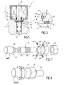
Figures 1 is a view in diagrammatic section showing an assembly according to the prior art; -
Figure 2 is a view in section to a larger scale of some details circled infigure 1 ; -
Figures 3, 4 and 5 are views in diagrammatic section showing an assembly according to an embodiment of the invention; -
Figure 6 is a view in section to a larger scale of some details infigure 4 , and -
Figure 7 and 8 are views in perspective showing different elements of a disassembling tool according to an embodiment of the invention; -
Figure 3 represents anassembly 30 for an electrically operated valve in the automotive field.Such assembly 30 aims to control the injection pressure of fuel provided through acommon rail 41 to different injectors of associated combustion chambers, the injectors and the combustion chambers not being represented. - For that purpose the
assembly 30 might perform, as a high pressure valve (HPV), at least one of the following main functions: - Lowering the pressure in the
common rail 41 by discharging fuel, - Heating the fuel provided to the
common rail 41 in cold start engine conditions, - Maintaining a minimum pressure in the common rail 41 (natural pressure) to start and run the engine in case of an open circuit of the actuator, or venting the
common rail 41 when the engine is switched off by discharging pressurized mixture of "air + fuel". - The
assembly 30 can also control the high pressure in thecommon rail 41 in specific modes of fuel distribution such as: - In absence or failure of an inlet metering valve delivering fuel quantity needed to generate pressure demand in rail,
- A fault on a high pressure sensor (HPS) measuring the rail pressure, and
- An overpressure in the high pressure circuit (PLV function).
- The
assembly 30 comprises acoil unit 32 wherein asolenoid 33 controls the movements of avalve 34 following an axis 36. - An elastically compressible
intermediate ring 40 is compressed between thecoil unit 32 and thehydraulic unit 35 while aclip ring 38 is located into radial cavities of thecoil unit 32 or thehydraulic unit 35 in order to maintain both units associated. The respective locations of these two cavities, or grooves, are suited in height so that they are positioned one facing the other when thecoil unit 32 comes into its operating position relatively to thehydraulic unit 35. - According to this embodiment of the invention, the
coil unit 32 presents a plurality ofslots 46 extending radially across thecoil unit 32 within the plane defined by theclip ring 38. - Through these
slots 46, theclip ring 38 can be removed from the radial cavity of thecoil unit 32 and maintained in the radial cavity of the hydraulic unit as represented infigure 4 . - In this
figure 4 , theassembly 30 is represented associated to atool 50 performing the separation of thecoil unit 32 from thehydraulic unit 35 without damaging any of these units. - For that purpose, the assembly 30 - removed from its operating position associated to a common rail 41 - is placed in contact with the
tool 50 whose shape fits part of theassembly 30 shape as acommon rail 41. - In this position,
arms 48 of thetool 50 face theslots 46 so that they can be pushed within theslots 46 until coming into contact with theclip ring 38. - The
arms 48 can further progress into theslots 46 so that theclip ring 38 is compressed and excluded from the cavity of thecoil unit 32 while being maintained in the radial cavity of thehydraulic unit 35 as represented infigure 4 . - In this position the
coil unit 32 moves away from thehydraulic unit 35 as represented infigure 5 since the elastically compressedring 40, arranged between thehydraulic unit 35 and thecoil unit 32 as described in the prior art, delivers a constant load in that sense. - In other words the
elastic ring 40 forces a displacement of thecoil unit 32 relatively to thehydraulic unit 35 as shown infigure 5 . - In this
figure 5 , thecoil unit 32 is represented in a perspective view showing an exterior view of one of theslots 46 of thecoil unit 32. It appears that theslot 46 extends itself axially so that thecoil unit 32 can move while thearms 48 maintain the clip ring within the radial cavity of the hydraulic unit. - In this embodiment, the
slots 46 also extend themselves axially from the clip ring plane until theextremity 52 of thecoil unit 32 facing the hydraulic unit so that thecoil unit 32 can be completely removed from the hydraulic unit while thearms 48 maintain theclip ring 38 compressed. - It has to be underlined that an
assembly 30 according to the invention can be manufactured according to already existing manufacturing process. Thus the invention does not increase the manufacturing of anassembly 30. - As illustrated in
figures 7 and 8 , disassembling of such anassembly 30 can be performed through atool 54 comprising acontact part 62 wherein theassembly 30 is positioned and maintained so that thearms 48 can be pushed across the coil unit slots as previously described infigure 4 . - In this embodiment the
tool 54 also presents a threadedpart 58 cooperating with anut 56 in order to block asupport 60 of thearms 48. - Thus the position of the
support 60 can precisely be determined towards theassembly 30, which ensures a precise position of thearms 48. In the embodiment, thearms 48 are threaded rods ofscrews 64 aimed to be screwed in the threadedslots 38. - The invention is not limited to the above description of a given embodiment and can be derived through different embodiments.
Claims (10)
- An assembly (30) for an electrically operated valve (34) in the automotive field aimed to increase the injection pressure of fuel distributed to combustion chambers, said assembly (30) comprising both a coil unit (32), wherein a solenoid (33) can control the movements of the electrically operated valve (34) in a housing along a given axis (36), and an hydraulic unit (35) to provide fuel at the injection pressure, a clip ring (38) being located into a cavity of the coil unit (32) and a cavity of the hydraulic unit (35) to maintain the coil unit (32) and the hydraulic unit (35) associated, characterized in that the coil unit (32) presents a plurality of slots (46) providing access to the clip ring (38), across the coil unit (32), from the exterior of the assembly (30).
- An assembly (30) according to claim 1 wherein the slots (46) extend themselves radially across the coil unit (32) in a plane defined by the clip ring (38).
- An assembly (30) according to claim 1 or 2 wherein the slots (46) extend themselves axially (36) on a length at least equal to the diameter of the clip ring (38).
- An assembly (30) according to claim 3 wherein the slots (46) extend themselves axially (36) until one extremity (52) of the coil unit (32).
- An assembly (30) according to any of the previous claims wherein the slots (46) are symmetrically disposed relatively to the assembly axis (35).
- An assembly (30) according to any of the previous claims wherein an elastically compressible intermediate ring (40) is compressed between the coil unit (32) and the hydraulic unit (35).
- A process for manufacturing an assembly (30) for an electrically operated valve (34) in the automotive field aimed to increase the injection pressure of fuel distributed to combustion chambers, said assembly (30) comprising both a coil unit (32), wherein a solenoid (33) can control the movements of the electrically operated valve (34) in a housing along a given axis (36), and an hydraulic unit (35) to provide fuel at the injection pressure, a clip ring (38) being located into a cavity of the coil unit (32) and a cavity of the hydraulic unit (35) to maintain the coil unit (32) and the hydraulic unit (35) associated, characterized in that it comprises the step of using a coil unit (32) according to any of the previous claims presenting a plurality of slots (46) providing access to the clip ring (38), across the coil unit (32), from the exterior of the assembly (30).
- A process for disassembling an assembly (30) comprising both a coil unit (32), wherein a solenoid can control the movements of the electrically operated valve in a housing along a given axis (35), and an hydraulic unit (35) to provide fuel at the injection pressure, a clip ring (38) being located into a cavity of the coil unit (32) and a cavity of the hydraulic unit (35) to maintain the coil unit (32) and the hydraulic unit (35) associated, according to any of the claims 1 to 6, characterized in that it comprises the step of pushing the clip ring (38) with arms (48) introduced through the slots (46)) until the coil unit (32) is disassembled from the hydraulic unit (35).
- A process according to claim 8 wherein it further comprises the step of using a tool (50, 54) presenting a contact part (62), whose shape fits part of the assembly shape, and a threaded part (58) wherein a nut (56) is fixed in order to block an intermediary support (60) comprising screws (64) whose threaded rod form the arms (48) aimed to be screwed in threaded slots (38).
- A disassembling tool (50, 54) aimed to operate on an assembly (30) according to any of the prior claims 1 to 6 comprising a contact part (62), whose shape fits part of the assembly shape, a threaded part (58) wherein a nut (56) is fixed in order to block an intermediary support (60) comprising screws (64) to be pushed in the threaded slots (38) of the assembly (30).
Priority Applications (6)
| Application Number | Priority Date | Filing Date | Title |
|---|---|---|---|
| EP20110170541 EP2538066A1 (en) | 2011-06-20 | 2011-06-20 | Assembly for an electrically operated valve |
| KR1020147000287A KR20140019024A (en) | 2011-06-20 | 2012-06-13 | Assembly for an electrically operated valve |
| CN201280030654.8A CN103688046A (en) | 2011-06-20 | 2012-06-13 | Components for Electric Valves |
| JP2014516272A JP2014523991A (en) | 2011-06-20 | 2012-06-13 | Motorized valve assembly |
| PCT/EP2012/061191 WO2012175384A1 (en) | 2011-06-20 | 2012-06-13 | Assembly for an electrically operated valve |
| US14/127,666 US20140196796A1 (en) | 2011-06-20 | 2012-06-13 | Assembly for an electrically operated valve |
Applications Claiming Priority (1)
| Application Number | Priority Date | Filing Date | Title |
|---|---|---|---|
| EP20110170541 EP2538066A1 (en) | 2011-06-20 | 2011-06-20 | Assembly for an electrically operated valve |
Publications (1)
| Publication Number | Publication Date |
|---|---|
| EP2538066A1 true EP2538066A1 (en) | 2012-12-26 |
Family
ID=46320921
Family Applications (1)
| Application Number | Title | Priority Date | Filing Date |
|---|---|---|---|
| EP20110170541 Withdrawn EP2538066A1 (en) | 2011-06-20 | 2011-06-20 | Assembly for an electrically operated valve |
Country Status (6)
| Country | Link |
|---|---|
| US (1) | US20140196796A1 (en) |
| EP (1) | EP2538066A1 (en) |
| JP (1) | JP2014523991A (en) |
| KR (1) | KR20140019024A (en) |
| CN (1) | CN103688046A (en) |
| WO (1) | WO2012175384A1 (en) |
Families Citing this family (4)
| Publication number | Priority date | Publication date | Assignee | Title |
|---|---|---|---|---|
| GB201411598D0 (en) * | 2014-06-30 | 2014-08-13 | Delphi International Operations Luxembourg S.�.R.L. | Pressure limiting valve |
| GB201509225D0 (en) * | 2015-05-29 | 2015-07-15 | Delphi Int Operations Lux Srl | High pressure valve |
| KR102589604B1 (en) * | 2015-10-27 | 2023-10-13 | 히다치 아스테모 가부시키가이샤 | Shock absorber and shock absorber assembly method |
| CN115479150A (en) * | 2022-08-04 | 2022-12-16 | 苏州航发航空零部件有限公司 | A combination valve body convenient for connecting external pipes |
Citations (8)
| Publication number | Priority date | Publication date | Assignee | Title |
|---|---|---|---|---|
| CH292199A (en) * | 1944-07-10 | 1953-07-31 | Gmbh Robert Bosch | Fuel injector. |
| US4209193A (en) * | 1977-05-17 | 1980-06-24 | Vetco, Inc. | Rigid connector for large diameter pipe |
| GB2156467A (en) * | 1984-03-26 | 1985-10-09 | Vetco Offshore Ind Inc | Snap type pipe coupling |
| DE4427597A1 (en) * | 1994-08-04 | 1996-02-08 | Teves Gmbh Alfred | Tube connection for brake line on vehicle |
| WO2002002983A1 (en) * | 2000-07-06 | 2002-01-10 | Anton Hummel Verwaltungs Gmbh | Connecting fitting for peripherally ribbed longitudinal bodies with a locking retaining projecting element |
| US20030152424A1 (en) * | 2001-02-21 | 2003-08-14 | Markus Nieslony | Clamping assembly |
| DE102007009963A1 (en) * | 2007-03-01 | 2008-09-04 | Robert Bosch Gmbh | Fuel injector for use with magnetic valve, has magnetic head with sleeve body, where sleeve body has magnetic core and magnetic coil, and magnetic coil is electrically connected through connector pins |
| WO2009103593A1 (en) * | 2008-02-22 | 2009-08-27 | Robert Bosch Gmbh | Injection valve with adhesively bonded magnet |
Family Cites Families (9)
| Publication number | Priority date | Publication date | Assignee | Title |
|---|---|---|---|---|
| US3345087A (en) * | 1964-06-18 | 1967-10-03 | Ventura Company | Conduit connectors |
| US3521911A (en) * | 1968-03-06 | 1970-07-28 | Vetco Offshore Ind Inc | Lockable and unlockable,releasable tool joints |
| US4830408A (en) * | 1981-06-05 | 1989-05-16 | Dril-Quip, Inc. | Connector assembly |
| GB8914931D0 (en) * | 1989-06-29 | 1989-08-23 | Plexus Ocean Syst Ltd | A releasable connector |
| DE3943419A1 (en) * | 1989-12-30 | 1991-07-04 | Bosch Gmbh Robert | FUEL INJECTION PUMP FOR INTERNAL COMBUSTION ENGINES, IN PARTICULAR PUMPEDUESE |
| DE4201570C2 (en) * | 1992-01-22 | 1995-04-13 | Danfoss As | Actuator |
| JP3604294B2 (en) * | 1998-12-11 | 2004-12-22 | 株式会社ボッシュオートモーティブシステム | Fuel injection pump |
| US6955337B2 (en) * | 2003-04-03 | 2005-10-18 | Delphi Technologies, Inc. | Pneumatic module |
| CN102003440B (en) * | 2010-11-02 | 2012-02-08 | 国营万峰无线电厂 | Circular tube connection structure and special assembling and disassembling tool thereof |
-
2011
- 2011-06-20 EP EP20110170541 patent/EP2538066A1/en not_active Withdrawn
-
2012
- 2012-06-13 KR KR1020147000287A patent/KR20140019024A/en not_active Ceased
- 2012-06-13 JP JP2014516272A patent/JP2014523991A/en active Pending
- 2012-06-13 WO PCT/EP2012/061191 patent/WO2012175384A1/en not_active Ceased
- 2012-06-13 CN CN201280030654.8A patent/CN103688046A/en active Pending
- 2012-06-13 US US14/127,666 patent/US20140196796A1/en not_active Abandoned
Patent Citations (8)
| Publication number | Priority date | Publication date | Assignee | Title |
|---|---|---|---|---|
| CH292199A (en) * | 1944-07-10 | 1953-07-31 | Gmbh Robert Bosch | Fuel injector. |
| US4209193A (en) * | 1977-05-17 | 1980-06-24 | Vetco, Inc. | Rigid connector for large diameter pipe |
| GB2156467A (en) * | 1984-03-26 | 1985-10-09 | Vetco Offshore Ind Inc | Snap type pipe coupling |
| DE4427597A1 (en) * | 1994-08-04 | 1996-02-08 | Teves Gmbh Alfred | Tube connection for brake line on vehicle |
| WO2002002983A1 (en) * | 2000-07-06 | 2002-01-10 | Anton Hummel Verwaltungs Gmbh | Connecting fitting for peripherally ribbed longitudinal bodies with a locking retaining projecting element |
| US20030152424A1 (en) * | 2001-02-21 | 2003-08-14 | Markus Nieslony | Clamping assembly |
| DE102007009963A1 (en) * | 2007-03-01 | 2008-09-04 | Robert Bosch Gmbh | Fuel injector for use with magnetic valve, has magnetic head with sleeve body, where sleeve body has magnetic core and magnetic coil, and magnetic coil is electrically connected through connector pins |
| WO2009103593A1 (en) * | 2008-02-22 | 2009-08-27 | Robert Bosch Gmbh | Injection valve with adhesively bonded magnet |
Also Published As
| Publication number | Publication date |
|---|---|
| WO2012175384A1 (en) | 2012-12-27 |
| JP2014523991A (en) | 2014-09-18 |
| KR20140019024A (en) | 2014-02-13 |
| CN103688046A (en) | 2014-03-26 |
| US20140196796A1 (en) | 2014-07-17 |
Similar Documents
| Publication | Publication Date | Title |
|---|---|---|
| US20140196796A1 (en) | Assembly for an electrically operated valve | |
| CN103328773B (en) | Method and apparatus for replacing a seal plate in an aircraft engine | |
| US10281068B2 (en) | Pipe connection arrangement, high-pressure fluid line system of a dual fuel engine, dual fuel engine and use of a tension nut | |
| US20130230392A1 (en) | Auxiliary member for assembly/disassembly of gas turbine casing, gas turbine having the same, assembly method of gas turbine casing, and disassembly method of gas turbine casing | |
| EP3088728B1 (en) | Fuel pump for a direct injection system with an improved hydraulic sealing of the intake valve | |
| EP3460334A1 (en) | Electronic fuel control for gas turbine engines | |
| US20150247406A1 (en) | Method for assembling and disassembling a rotor having a number of rotor components of an axial flow turbomachine and such a rotor | |
| EP3045269B1 (en) | Seal extraction tool | |
| US8992166B2 (en) | Turbocharger | |
| EP2538067A1 (en) | Assembly for an electrically operated valve | |
| US10030619B2 (en) | Connector for mounting sensor in pressurized fluid system | |
| RU2445506C1 (en) | Device for equalisation and prestress of components of fuel injector assembly | |
| US20200240563A1 (en) | Polygon Wire Ring For Retaining An Internal Component Of A Valve To An External Component Thereof | |
| CN109564834A (en) | Drive rod and method of making a drive rod | |
| US10830099B2 (en) | Fuse joint with fenestrated fuse pin | |
| US9284889B2 (en) | Flexible seal system for a gas turbine engine | |
| CN106471272A (en) | Coil spring fixed structure and double cylinder reciprocating pump | |
| US9739176B2 (en) | Turbomachine | |
| CN104975949A (en) | Exhaust gas turbocharger | |
| US11513034B2 (en) | Probe adapter for a blade outer air seal and method for using same | |
| CN105518286A (en) | Holder and assembly having a fuel dispenser and a plurality of holders | |
| CN103307425B (en) | The handling basis of quick assembling/disassembling mechanism is set | |
| CN102748398A (en) | Combined bearing clearance accurate adjustment nut for eliminating run-out errors | |
| CN107781438A (en) | Regulating valve, valve element and valve shaft | |
| US10724394B2 (en) | Steam turbine and method of assembling and disassembling the same |
Legal Events
| Date | Code | Title | Description |
|---|---|---|---|
| PUAI | Public reference made under article 153(3) epc to a published international application that has entered the european phase |
Free format text: ORIGINAL CODE: 0009012 |
|
| AK | Designated contracting states |
Kind code of ref document: A1 Designated state(s): AL AT BE BG CH CY CZ DE DK EE ES FI FR GB GR HR HU IE IS IT LI LT LU LV MC MK MT NL NO PL PT RO RS SE SI SK SM TR |
|
| AX | Request for extension of the european patent |
Extension state: BA ME |
|
| 17P | Request for examination filed |
Effective date: 20130626 |
|
| RAX | Requested extension states of the european patent have changed |
Extension state: BA Payment date: 20130626 Extension state: ME Payment date: 20130626 |
|
| RBV | Designated contracting states (corrected) |
Designated state(s): AL AT BE BG CH CY CZ DE DK EE ES FI FR GB GR HR HU IE IS IT LI LT LU LV MC MK MT NL NO PL PT RO RS SE SI SK SM TR |
|
| 17Q | First examination report despatched |
Effective date: 20131018 |
|
| RIC1 | Information provided on ipc code assigned before grant |
Ipc: F16L 27/08 20060101ALI20131211BHEP Ipc: F02M 51/00 20060101ALI20131211BHEP Ipc: F02M 61/16 20060101ALI20131211BHEP Ipc: F16K 27/02 20060101AFI20131211BHEP Ipc: F02M 59/46 20060101ALI20131211BHEP |
|
| RAP1 | Party data changed (applicant data changed or rights of an application transferred) |
Owner name: DELPHI INTERNATIONAL OPERATIONS LUXEMBOURG S.A.R.L |
|
| GRAP | Despatch of communication of intention to grant a patent |
Free format text: ORIGINAL CODE: EPIDOSNIGR1 |
|
| INTG | Intention to grant announced |
Effective date: 20140429 |
|
| STAA | Information on the status of an ep patent application or granted ep patent |
Free format text: STATUS: THE APPLICATION IS DEEMED TO BE WITHDRAWN |
|
| 18D | Application deemed to be withdrawn |
Effective date: 20140910 |