EP2538059A1 - Abnormality detection device for fuel property detection device - Google Patents
Abnormality detection device for fuel property detection device Download PDFInfo
- Publication number
- EP2538059A1 EP2538059A1 EP10846117A EP10846117A EP2538059A1 EP 2538059 A1 EP2538059 A1 EP 2538059A1 EP 10846117 A EP10846117 A EP 10846117A EP 10846117 A EP10846117 A EP 10846117A EP 2538059 A1 EP2538059 A1 EP 2538059A1
- Authority
- EP
- European Patent Office
- Prior art keywords
- fuel
- abnormality
- temperature
- detecting
- flow
- Prior art date
- Legal status (The legal status is an assumption and is not a legal conclusion. Google has not performed a legal analysis and makes no representation as to the accuracy of the status listed.)
- Granted
Links
- 239000000446 fuel Substances 0.000 title claims abstract description 362
- 230000005856 abnormality Effects 0.000 title claims abstract description 104
- 238000001514 detection method Methods 0.000 title description 32
- 238000002485 combustion reaction Methods 0.000 claims description 13
- 238000012545 processing Methods 0.000 claims description 11
- 230000003213 activating effect Effects 0.000 claims description 7
- 230000008901 benefit Effects 0.000 claims description 5
- 238000012937 correction Methods 0.000 claims description 5
- 238000010438 heat treatment Methods 0.000 claims description 4
- LFQSCWFLJHTTHZ-UHFFFAOYSA-N Ethanol Chemical compound CCO LFQSCWFLJHTTHZ-UHFFFAOYSA-N 0.000 description 134
- 238000010586 diagram Methods 0.000 description 10
- 238000000034 method Methods 0.000 description 4
- 239000002699 waste material Substances 0.000 description 4
- 230000004913 activation Effects 0.000 description 3
- 230000008859 change Effects 0.000 description 3
- 239000000498 cooling water Substances 0.000 description 3
- 239000002828 fuel tank Substances 0.000 description 3
- 238000002347 injection Methods 0.000 description 3
- 239000007924 injection Substances 0.000 description 3
- 238000005259 measurement Methods 0.000 description 3
- 230000004044 response Effects 0.000 description 3
- 238000009834 vaporization Methods 0.000 description 3
- 230000008016 vaporization Effects 0.000 description 3
- 239000000470 constituent Substances 0.000 description 2
- 230000007423 decrease Effects 0.000 description 2
- 230000000694 effects Effects 0.000 description 2
- 239000002028 Biomass Substances 0.000 description 1
- 230000002159 abnormal effect Effects 0.000 description 1
- 238000002835 absorbance Methods 0.000 description 1
- 230000002411 adverse Effects 0.000 description 1
- 238000007796 conventional method Methods 0.000 description 1
- 238000003745 diagnosis Methods 0.000 description 1
- 238000012544 monitoring process Methods 0.000 description 1
- 230000000704 physical effect Effects 0.000 description 1
- 230000008569 process Effects 0.000 description 1
- 230000000630 rising effect Effects 0.000 description 1
- 239000000243 solution Substances 0.000 description 1
- 238000011144 upstream manufacturing Methods 0.000 description 1
- XLYOFNOQVPJJNP-UHFFFAOYSA-N water Substances O XLYOFNOQVPJJNP-UHFFFAOYSA-N 0.000 description 1
Images


Classifications
-
- F—MECHANICAL ENGINEERING; LIGHTING; HEATING; WEAPONS; BLASTING
- F02—COMBUSTION ENGINES; HOT-GAS OR COMBUSTION-PRODUCT ENGINE PLANTS
- F02D—CONTROLLING COMBUSTION ENGINES
- F02D41/00—Electrical control of supply of combustible mixture or its constituents
- F02D41/0025—Controlling engines characterised by use of non-liquid fuels, pluralities of fuels, or non-fuel substances added to the combustible mixtures
-
- F—MECHANICAL ENGINEERING; LIGHTING; HEATING; WEAPONS; BLASTING
- F02—COMBUSTION ENGINES; HOT-GAS OR COMBUSTION-PRODUCT ENGINE PLANTS
- F02D—CONTROLLING COMBUSTION ENGINES
- F02D41/00—Electrical control of supply of combustible mixture or its constituents
- F02D41/22—Safety or indicating devices for abnormal conditions
- F02D41/222—Safety or indicating devices for abnormal conditions relating to the failure of sensors or parameter detection devices
-
- F—MECHANICAL ENGINEERING; LIGHTING; HEATING; WEAPONS; BLASTING
- F02—COMBUSTION ENGINES; HOT-GAS OR COMBUSTION-PRODUCT ENGINE PLANTS
- F02M—SUPPLYING COMBUSTION ENGINES IN GENERAL WITH COMBUSTIBLE MIXTURES OR CONSTITUENTS THEREOF
- F02M37/00—Apparatus or systems for feeding liquid fuel from storage containers to carburettors or fuel-injection apparatus; Arrangements for purifying liquid fuel specially adapted for, or arranged on, internal-combustion engines
- F02M37/0076—Details of the fuel feeding system related to the fuel tank
- F02M37/0082—Devices inside the fuel tank other than fuel pumps or filters
-
- F—MECHANICAL ENGINEERING; LIGHTING; HEATING; WEAPONS; BLASTING
- F02—COMBUSTION ENGINES; HOT-GAS OR COMBUSTION-PRODUCT ENGINE PLANTS
- F02D—CONTROLLING COMBUSTION ENGINES
- F02D2200/00—Input parameters for engine control
- F02D2200/02—Input parameters for engine control the parameters being related to the engine
- F02D2200/06—Fuel or fuel supply system parameters
- F02D2200/0606—Fuel temperature
-
- F—MECHANICAL ENGINEERING; LIGHTING; HEATING; WEAPONS; BLASTING
- F02—COMBUSTION ENGINES; HOT-GAS OR COMBUSTION-PRODUCT ENGINE PLANTS
- F02D—CONTROLLING COMBUSTION ENGINES
- F02D2200/00—Input parameters for engine control
- F02D2200/02—Input parameters for engine control the parameters being related to the engine
- F02D2200/06—Fuel or fuel supply system parameters
- F02D2200/0611—Fuel type, fuel composition or fuel quality
-
- Y—GENERAL TAGGING OF NEW TECHNOLOGICAL DEVELOPMENTS; GENERAL TAGGING OF CROSS-SECTIONAL TECHNOLOGIES SPANNING OVER SEVERAL SECTIONS OF THE IPC; TECHNICAL SUBJECTS COVERED BY FORMER USPC CROSS-REFERENCE ART COLLECTIONS [XRACs] AND DIGESTS
- Y02—TECHNOLOGIES OR APPLICATIONS FOR MITIGATION OR ADAPTATION AGAINST CLIMATE CHANGE
- Y02T—CLIMATE CHANGE MITIGATION TECHNOLOGIES RELATED TO TRANSPORTATION
- Y02T10/00—Road transport of goods or passengers
- Y02T10/10—Internal combustion engine [ICE] based vehicles
- Y02T10/40—Engine management systems
Definitions
- the present invention relates to an apparatus for detecting abnormality for a fuel property detecting apparatus.
- values of engine control parameters have to be appropriately corrected in response to the property of the fuel.
- various apparatuses for detecting the fuel property in order to optimally control the internal combustion engine in response to the fuel property.
- OBD on-board diagnosis
- Japanese Utility Model Laid-Open No. 2-112949 discloses a technique of outputting an alarm signal when the variation of the alcohol concentration of an alcohol blended fuel detected by an alcohol concentration sensor is equal to or higher than a predetermined value, and monitoring the variation of the air fuel ratio for a predetermined length of time if the alarm signal is output, and determining that there is an abnormality in the alcohol concentration sensor if a deviation of the air fuel ratio is detected.
- the conventional technique described above cannot detect a failure of the sensor because the detection value of the fuel property sensor shows no change.
- the detection value of the sensor can change when the fuel flow is disturbed by a foreign matter clogging the flow channel in the vicinity of the sensor. Such a situation may be erroneously determined as a failure of the fuel property sensor.
- the present invention has been devised in view of the circumstances described above, and an object of the present invention is to provide an apparatus for detecting abnormality capable of accurately detecting whether or not there is an abnormality in a fuel property detecting apparatus.
- First aspect of the present invention is an apparatus for detecting abnormality for a fuel property detecting apparatus, comprising:
- Second aspect of the present invention is the apparatus for detecting abnormality for a fuel property detecting apparatus according to the first aspect, wherein the abnormality determining means comprises fuel flow abnormality determining means for determining whether or not there is an abnormality in a flow of the fuel in the vicinity of the sensor part and failure determining means for determining whether or not there is a failure of the fuel property detecting apparatus itself and makes the failure determining means perform the determination when the fuel flow abnormality determining means determines that there is no abnormality in the flow of the fuel in the vicinity of the sensor part.
- the abnormality determining means comprises fuel flow abnormality determining means for determining whether or not there is an abnormality in a flow of the fuel in the vicinity of the sensor part and failure determining means for determining whether or not there is a failure of the fuel property detecting apparatus itself and makes the failure determining means perform the determination when the fuel flow abnormality determining means determines that there is no abnormality in the flow of the fuel in the vicinity of the sensor part.
- Third aspect of the present invention is the apparatus for detecting abnormality for a fuel property detecting apparatus according to the first or the second aspect, wherein the abnormality determining means comprises fuel flow abnormality determining means for determining whether or not there is an abnormality in a flow of the fuel in the vicinity of the sensor part, and the fuel flow abnormality determining means comprises:
- Fourth aspect of the present invention is the apparatus for detecting abnormality for a fuel property detecting apparatus according to the second or the third aspect, further comprising:
- Fifth aspect of the present invention is the apparatus for detecting abnormality for a fuel property detecting apparatus according to the second or the third aspect, further comprising avoiding means for avoiding performing the determination by the fuel flow abnormality determining means when the flow rate of the fuel passing through the fuel channel is lower than a predetermined value.
- the apparatus for detecting abnormality for a fuel property detecting apparatus comprises failure determining means for determining whether or not there is a failure of the fuel property detecting apparatus itself, the sensor part detects a value that has a temperature dependency, the fuel property detecting apparatus comprises temperature correcting means for calculating a fuel property value by performing a correction processing for a value detected by the sensor part based on the temperature of the fuel detected by the temperature detecting means, and the failure determining means obtains fuel property values subjected to the correction processing at a plurality of different points of fuel temperature when the heater is activated, and determines whether or not there is a failure of the fuel property detecting apparatus based on the difference between the fuel property values at the different points.
- Seventh aspect of the present invention is the apparatus for detecting abnormality for a fuel property detecting apparatus according to the sixth aspect, wherein the sensor part is provided on a fuel distribution channel that distributes the fuel to a fuel injector in each cylinder of the internal combustion engine or in a vicinity of the fuel distribution channel, and the heater is capable of heating the fuel in the fuel distribution channel.
- Eighth aspect of the present invention is the apparatus for detecting abnormality for a fuel property detecting apparatus according to the seventh aspect, wherein the failure determining means performs the determination by taking advantage of an opportunity of activating the heater during cold start of the internal combustion engine.
- Ninth aspect of the present invention is the apparatus for detecting abnormality for a fuel property detecting apparatus according to the seventh or the eighth aspect, further comprising means for controlling energization of the heater based on the temperature of the fuel detected by the temperature detecting means, during cold start of the internal combustion engine.
- whether or not there is an abnormality in the fuel property detecting apparatus can be quickly and accurately detected by raising the temperature of the fuel in the vicinity of the sensor part of the fuel property detecting apparatus by means for the heater and detecting the temperature in the vicinity of the sensor part at this point in time.
- the second aspect of the present invention it is possible to accurately distinguish between abnormalities in the flow of the fuel in the vicinity of the sensor part and failures of the fuel property detecting apparatus itself.
- whether or not there is an abnormality in the flow of the fuel in the vicinity of the sensor part can be determined by comparing the temperature estimated based on the amount of energy input by the heater and the flow rate of the fuel in the fuel channel and the actually detected temperature. In this way, whether or not there is an abnormality in the flow of the fuel in the vicinity of the sensor part can be accurately detected in a simple manner.
- the detection precision can be improved because the abnormality detection control for the flow of the fuel in the vicinity of the sensor part can be performed when the flow rate of the fuel in the fuel channel is high.
- the detection precision can be improved because the abnormality detection control for the flow of the fuel in the vicinity of the sensor part can be performed when the flow rate of the fuel in the fuel channel is high.
- the heater for heating the fuel in the fuel distribution channel can be used for abnormality detection for the fuel property detecting apparatus and the fuel property detecting apparatus does not have to have a dedicated heater.
- the structure of the fuel property detecting apparatus can be simplified, and the cost can be reduced.
- the failure determining means can perform the failure detection for the fuel property detecting apparatus by taking advantage of the opportunity of activating the heater that heats the fuel in the fuel distribution channel during cold start of the internal combustion engine. Therefore, there is no need to activate the heater for the purpose of detecting a failure of the fuel property detecting apparatus, so that energy waste can be reduced.
- energization of the heater that heats the fuel in the fuel distribution channel can be controlled based on the detected fuel temperature. Therefore, the temperature of the fuel supplied to the internal combustion engine during cold start can be raised to a necessary and sufficient extent, so that poor vaporization of the fuel can be prevented with reliability, and at the same time, energy waste can be reduced.
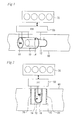
- FIG. 1 is a schematic diagram showing a configuration of an apparatus according to an embodiment 1 of the present invention.
- the apparatus according to this embodiment is to be mounted on an automobile that uses a fuel containing a constituent (ethanol in this embodiment) derived from biomass, and has a function of detecting the concentration of the constituent in the fuel.
- a constituent ethanol in this embodiment
- the apparatus comprises electrodes 10 and 12, a temperature sensor 14, a heater 18, and an electronic control unit (ECU) 50.
- the electrodes 10 and 12 and the temperature sensor 14 are electrically connected to the ECU 50.
- the ECU 50 is configured to be capable of controlling energization of the heater 18.
- various actuators such as a fuel injector, an ignition plug and a throttle valve, and various sensors, such as a crank angle sensor and an air fuel ratio sensor, provided for an internal combustion engine (referred to simply as an engine, hereinafter) 70 are electrically connected to the ECU 50.
- the electrodes 10 and 12 are disposed in a fuel channel 60 that feeds the fuel from a fuel tank (not shown) to the fuel injector of the engine 70.
- the electrodes 10 and 12 have a cylindrical shape and are concentrically arranged with the electrode 12 with the smaller diameter inserted in the electrode 10 with the larger diameter.
- the electrodes 10 and 12 are disposed so that the center lines thereof are parallel to the direction of the flow of the fuel in the fuel channel 60. This facilitates the flow of the fuel through the gap between the electrodes 10 and 12 and ensures that the fuel is prevented from dwelling in the gap between the electrodes 10 and 12.
- the temperature sensor 14 is a thermistor, for example, and is disposed close to the electrodes 10 and 12.
- the temperature sensor 14 can detect the temperature of the fuel between the electrodes 10 and 12.
- the heater 18 is disposed close to the electrodes 10 and 12. The temperature of the fuel between the electrodes 10 and 12 can be raised by energizing the heater 18 to heat the fuel.
- FIG. 2 is a schematic diagram showing another example of the configuration of the apparatus according to the embodiment 1 of the present invention.
- the electrode 10 with the larger diameter and the electrode 12 with the smaller diameter which have a cylindrical shape and are concentrically arranged, are disposed so that the center lines thereof are perpendicular to the direction of the flow of the fuel in the fuel channel 60.
- FIG. 2 shows cross sections of the electrodes 10 and 12. Two openings 20 disposed in alignment with the direction of the flow of the fuel are formed in the side wall of the outer electrode 10.
- the fuel flowing through the fuel channel 60 can enter the gap between the electrodes 10 and 12 through the opening 20 on the upstream side and exit through the opening 20 on the downstream side. In this way, the fuel can readily flow through the gap between the electrodes 10 and 12, and the fuel can be prevented from dwelling in the gap between the electrodes 10 and 12 with reliability.
- the temperature sensor 14 and the heater 18 are disposed inside the electrode 12.
- the electrode 12 has a closed end so that no fuel enters the interior of the electrode 12. Therefore, the temperature sensor 14 and the heater 18 are not in direct contact with the fuel.
- the temperature of the fuel in the gap between the electrodes 10 and 12 approximately equals to the temperature in the electrode 12, so that the temperature detected by the temperature sensor 14 can be regarded as the temperature of the fuel between the electrodes 10 and 12.
- Heat generated by the heater 18 is transferred to the fuel in the gap between the electrodes 10 and 12, so that the temperature of the fuel between the electrodes 10 and 12 can be raised by the heater 18.
- FIG. 2 The apparatus shown in FIG. 2 is the same as the apparatus shown in FIG. 1 in the other respects than described above. Either of the apparatus configurations shown in FIGS. 1 and 2 can be used to implement this embodiment. The following description holds true for both the apparatus configurations shown in FIGS. 1 and 2 .
- the ECU 50 has a function of detecting (measuring) the capacitance between the electrodes 10 and 12.
- the capacitance between the electrodes 10 and 12 (referred to simply as a capacitance hereinafter) varies with the relative dielectric constant of the fuel between the electrodes 10 and 12.
- the ethanol containing fuel varies in relative dielectric constant with the concentration of the ethanol contained therein, and therefore, the capacitance varies with the ethanol concentration of the fuel between the electrodes 10 and 12.
- FIG. 3 is a diagram showing relationships between the ethanol concentration, the temperature and the capacitance of the ethanol containing fuel.
- the ECU 50 previously stores a map such as that shown in FIG. 3 (referred to as an ethanol concentration calculating map, hereinafter). Based on the detected capacitance, the fuel temperature detected by the temperature sensor 14, and the ethanol concentration calculating map shown in FIG. 3 , the ECU 50 can calculate the ethanol concentration.
- an abnormality in the flow of the fuel between the electrodes is detected as described below.
- the temperature of the fuel between the electrodes 10 and 12 detected by the temperature sensor 14 (referred to as an electrode part temperature hereinafter) is determined by the balance between the amount of heat applied by the heater 18 (the amount of energy input) and the amount of heat removed by the flow of the fuel. Therefore, the electrode part temperature can be estimated based on the amount of heat applied by the heater 18 and the flow rate of the fuel in the fuel channel 60.
- the amount of heat removed decreases, so that the electrode part temperature detected by the temperature sensor 14 is higher than the estimated electrode part temperature. Therefore, whether the flow of the fuel between the electrodes is normal or abnormal can be determined by comparing the electrode part temperature detected by the temperature sensor 14 with the estimated electrode part temperature.
- FIG. 4 is a flowchart showing a routine performed by the ECU 50 to determine whether or not there is an abnormality in the flow of the fuel between the electrodes according to this embodiment.
- the detection value of the temperature sensor 14 is first obtained before start of energization of the heater 18 (Step 100).
- the detection value will be referred to as an initial electrode part temperature hereinafter and denoted by a symbol To.
- energization of the heater 18 is started (Step 102).
- Step 104 a process of estimating the electrode part temperature is performed (Step 104).
- the estimated value will be referred to an estimated electrode part temperature and denoted by a symbol Ts.
- the estimated electrode part temperature Ts is calculated based on the initial electrode part temperature To obtained in Step 102, the amount of electric power applied to the heater 18 (referred to as a heater power hereinafter), and the flow rate of the fuel in the fuel channel 60.
- FIG. 5 is a map used for calculating the estimated electrode part temperature Ts.
- the heater power can be regarded as being equal to the amount of heat applied by the heater 18 (the amount of energy input).
- the electrode part temperature rises beyond the initial electrode part temperature T 0 more significantly as the amount of applied heat (heater power) increases.
- the electrode part temperature lowers because the amount of removed heat increases. That is, the electrode part temperature rises as the fuel flow rate decreases.
- the estimated electrode part temperature Ts can be calculated from the map shown in FIG. 5 .
- the flow rate of the fuel in the fuel channel 60 is proportional to the amount of fuel consumed by the engine 70, and therefore, the ECU 50 can calculate the fuel flow rate based on the fuel injection amount from the fuel injector.
- Step 106 the estimated electrode part temperature Ts calculated in Step 104 and a measurement value T of the electrode part temperature measured at this point in time by the temperature sensor 14 are compared with each other (Step 106). Specifically, it is determined whether the following formula holds or not. Ts + ⁇ ⁇ T
- ⁇ denotes a value previously set as a maximum allowable error with which the value falls within a normal range. If it is determined in Step 106 that the formula (1) holds, the measured value T of the electrode part temperature can be regarded as being significantly higher than the estimated electrode part temperature Ts. In this case, it can be decided that the deviation of the measured value T of the electrode part temperature from the estimated electrode part temperature Ts is due to an abnormality in the flow of the fuel between the electrodes. Thus, in this case, it is determined that there is an abnormality in the flow of the fuel between the electrodes (Step 108).
- Step 110 if it is determined in Step 106 that the formula (1) does not hold, the measured value T of the electrode part temperature is not significantly higher than the estimated electrode part temperature Ts, so that it can be decided that the fuel normally flows between the electrodes 10 and 12. Thus, in this case, it is determined that the flow of the fuel between the electrodes is normal (Step 110).
- the abnormality detecting control for the flow of the fuel between the electrodes described above can be performed any time when the fuel is flowing in the fuel channel 60.
- the abnormality detection precision is higher when the flow rate of the fuel in the fuel channel 60 is somewhat high. This is because, if the flow rate of the fuel in the fuel channel 60 is low (that is, the engine load is low, and the fuel consumption is low), the flow of the fuel between the electrodes is intrinsically slow, so that it is difficult to determine whether or not there is an abnormality in the flow of the fuel between the electrodes.
- FIG. 6 is a flowchart showing a routine performed by the ECU 50 to perform such a control.
- Step 120 it is determined whether a condition for performing the abnormality detecting control for the flow of the fuel between the electrodes is met or not.
- the abnormality detecting control for the flow of the fuel between the electrodes is performed at predetermined times, such as every predetermined time and once in each trip from start to end of the engine.
- Step 120 it is determined whether the predetermined time to perform the abnormality detecting control has come or not.
- Step 120 If it is determined in Step 120 that the abnormality detecting control for the flow of the fuel between the electrodes can be performed, the control to increase the flow rate of the fuel in the fuel channel 60 is performed (Step 122). This control can be performed as described below, for example.
- Step 124 the processing of the routine shown in FIG. 4 described above is performed.
- the control according to the routine shown in FIG. 6 described above allows the abnormality detecting control for the flow of the fuel between the electrodes to be performed in a state where the fuel flow rate is high and thus can improve the detection precision.
- FIG. 7 is a flowchart showing a routine performed by the ECU 50 to perform such a control.
- the same steps as those in the routine shown in FIG. 6 are denoted by the same reference numerals, and description thereof will be omitted or simplified.
- Step 120 if it is determined in Step 120 that the condition to perform the abnormality detecting control for the flow of the fuel between the electrodes is met, the current flow rate of the fuel in the fuel channel 60 is then obtained, and it is determined whether or not the value is equal to or higher than a predetermined value (Step 126).
- the predetermined value is a criterion value that indicates whether or not the abnormality in the flow of the fuel between the electrodes can be detected with sufficiently high precision. If it is determined in Step 126 that the current fuel flow rate is lower than the predetermined value, it can be predicted that the detection cannot be performed with sufficient precision, so that the abnormality detecting control for the flow of the fuel between the electrodes is not performed.
- Step 126 if it is determined in Step 126 that the current fuel flow rate is equal to or higher than the predetermined value, it can be predicted that the detection can be performed with sufficient precision, so that the abnormality detecting control for the flow of the fuel between the electrodes is performed (Step 124).
- This control also allows the abnormality detecting control for the flow of the fuel between the electrodes to be performed in a state where the fuel flow rate is high and thus can improve the detection precision.
- the embodiment 1 described above concerns an application of the present invention to an apparatus that detects a fuel property based on a capacitance.
- the present invention is not limited to this application and can be applied to an apparatus that detects a fuel property by measuring other physical quantities of the fuel, such as the index of refraction and the absorbance, for example.
- the electrodes 10 and 12 correspond to a "sensor part" according to the first aspect of the present invention
- the ethanol concentration corresponds to a "fuel property” according to the first aspect of the present invention
- the temperature sensor 14 corresponds to "temperature detecting means” according to the first aspect of the present invention
- the capacitance corresponds to a "value having a temperature dependency” according to the sixth aspect of the present invention.
- the ECU 50 implements "fuel flow abnormality determining means" according to the second and third aspects of the present invention by performing the processing of the routine shown in FIG. 4
- Step 7 implements "avoiding means” according to the fifth aspect of the present invention by performing the processings of Steps 120 and 126, and implements "temperature correcting means” according to the sixth aspect of the present invention by calculating the ethanol concentration (fuel property value) based on the detected capacitance and fuel temperature and the map shown in FIG. 3 .
- FIGS. 8 to 10 An embodiment 2 of the present invention will be described with reference to FIGS. 8 to 10 .
- the following description will be mainly focused on differences from the embodiment 1 described above, and common things will be only simply described or not be described.
- FIG. 8 is a schematic diagram showing a configuration of an apparatus according to the embodiment 2 of the present invention.
- a fuel injector 22 provided in each cylinder of an engine 70 of the in-line four cylinder type is connected to a delivery pipe (fuel distribution channel) 24.
- the fuel fed from the fuel tank is distributed to the fuel injector 22 in each cylinder through the delivery pipe 24.
- the delivery pipe 24 is provided with a heater 26 capable of heating the fuel in the delivery pipe 24. Energization of the heater 26 is controlled by an ECU 50.
- the fuel in the delivery pipe 24 can be heated by energizing the heater 26, so that the temperature of the fuel fed to the fuel injector 22 can be raised.
- a fuel containing a high concentration of ethanol which is hard to vaporize at low temperatures, is used, poor vaporization of the fuel in the cold start can be prevented, and the startability and the emission characteristics can be improved.
- a fuel property sensor unit 28 is provided on a fuel channel 30 in the vicinity of an inlet of the delivery pipe 24.
- the fuel property sensor unit 28 includes electrodes for capacitance detection and a temperature sensor that detects the temperature of the fuel between the electrodes.
- the arrangement of the electrodes and the temperature sensor can be the same as the arrangement shown in FIG. 1 or 2 , for example. However, the fuel property sensor unit 28 does not have the heater 18.
- FIG. 9 is a schematic diagram showing another example of the configuration of the apparatus according to the embodiment 2 of the present invention.
- the fuel property sensor unit 28 may be provided on the delivery pipe 24 as shown in FIG. 9 .
- the configuration shown in FIG. 9 is the same as the configuration shown in FIG. 8 .
- Either of the configurations shown in FIGS. 8 and 9 can be used to implement this embodiment. The following description holds true for both the configurations shown in FIGS. 8 and 9 unless otherwise described.
- the ECU 50 can calculate the ethanol concentration of the fuel supplied to the engine 70 through the fuel channel 30 based on the capacitance and fuel temperature detected by the fuel property sensor unit 28 and the ethanol concentration calculating map shown in FIG. 3 .
- determination of whether or not there is an abnormality in the ethanol concentration detecting apparatus is made as described below. Since the relative dielectric constant of ethanol varies with temperature as described above, the capacitance varies with the fuel temperature even if the ethanol concentration is kept constant. In view of this, a correction processing based on the fuel temperature using the ethanol concentration calculating map shown in FIG. 3 is performed to calculate the ethanol concentration.
- whether or not there is an abnormality in the ethanol concentration detecting apparatus is determined by calculating the ethanol concentration based on the capacitances detected at two different points of fuel temperature and determining whether or not the calculated ethanol concentrations agree with each other. If the ethanol concentration detecting apparatus is normal, the ethanol concentrations measured at the two different points of fuel temperature must agree with each other. Therefore, if the ethanol concentrations measured at the two different points of fuel temperature do not agree with each other, it can be determined that there is an abnormality in the ethanol concentration detecting apparatus. When there is an abnormality in the ethanol concentration detecting apparatus, there is low probability that the two ethanol concentration values determined from the difference capacitance values detected at the two different points of fuel temperature happen to agree with each other. Therefore, if the ethanol concentrations calculated at the two different points of fuel temperature agree with each other, it can be determined that the ethanol concentration detecting apparatus is normal.
- the measurement of the ethanol concentration at two different points of fuel temperature is performed by taking advantage of the opportunity of activating the heater 26 during cold start of the engine 70.
- the temperature of the fuel in the fuel property sensor unit 28 is low before activation of the heater 26 and high after activation of the heater 26. Accordingly, measurements of the ethanol concentration at two different points of fuel temperature can be obtained by detecting the ethanol concentration at the times before and after activation of the heater 26.
- FIG. 10 is a flowchart showing a routine performed to implement the functions described above by the ECU 50 in response to a request to start the engine 70 according to this embodiment.
- the routine shown in FIG. 10 it is first determined whether or not the temperature of engine cooling water detected by a water temperature sensor (not shown) is equal to or lower than a predetermined cold criterion value and whether or not the temperature of the fuel detected by the temperature sensor in the fuel property sensor unit 28 is equal to or lower than the predetermined cold criterion value (Step 200).
- Step 200 If it is determined in Step 200 that at least one of the engine cooling water temperature and the fuel temperature is higher than the cold criterion value, it is determined that the engine 70 is in the warmed-up state. In this case, it can be determined that, if preheating of the fuel in the delivery pipe 24 is omitted, there is no adverse influence on the startability or the emission characteristics. Thus, in this case, the engine 70 is started without energizing the heater 26 (Step 214).
- the heater 26 is energized to heat the fuel in the delivery pipe 24 (Step 204).
- the temperature of the fuel between the electrodes in the fuel property sensor unit 28 immediately rises.
- the engine 70 has not been started and the fuel in the delivery pipe 24 and the fuel channel 30 is not flowing at this point in time, so that the heat applied by the heater 26 is readily transferred to the fuel property sensor unit 28 to raise the temperature of the fuel between the electrodes.
- Step 204 based on the temperature detected by the temperature sensor in the fuel property sensor unit 28, the amount of energization of the heater 26 can be controlled so that the temperature of the fuel in the delivery pipe 24 falls within a predetermined range. This ensures that the temperature of the fuel in the delivery pipe 24 is prevented from failing to rise to a fuel temperature required to prevent poor vaporization of the fuel at the start of the engine or from rising too high and leading to a waste of energy.
- the capacitance is detected between the electrodes in the fuel property sensor unit 28, and an ethanol concentration E2 is calculated based on the ethanol concentration calculating map (Step 206). Since the temperature of the fuel in the vicinity of the fuel property sensor unit 28 has been raised by the heat from the heater 26 as described above, the fuel temperature T2 is higher than the fuel temperature T1 (T2 > T1).
- Step 208 it is determined whether or not the absolute value
- Step 208 if it is determined in Step 208 that
- Step 214 After it is determined whether or not the ethanol concentration detecting apparatus is normal or has failed as described above, the engine 70 is started (Step 214).
- the failure detection described above can be performed by taking advantage of the opportunity of activating the heater 26 during cold start. Consequently, the fuel does not have to be heated for the purpose of failure detection, and accordingly, energy waste is reduced.
- the failure detection is performed before the engine is started, when the fuel is not flowing. Consequently, the actual ethanol concentration in the vicinity of the fuel property sensor unit 28 does not differ between the time of calculation of the ethanol concentration E1 at the fuel temperature T1 and the time of calculation of the ethanol concentration E2 at the fuel temperature T2. Therefore, erroneous determination can be prevented with reliability.
- the time to perform the failure detection is not limited to during cold start, and the same failure detection control as described above can also be performed by activating the heater 26 in any period during operation of the engine 70.
- the failure detection control described above with regard to this embodiment may be performed without using the heater 26 on the delivery pipe 24. That is, the fuel property sensor unit 28 may be provided with the heater 18 provided in the apparatus shown in FIG. 1 or 2 , and the same failure detection control as described above may be performed by activating the heater 18. In this case, the fuel property sensor unit 28 does not have to be provided on the delivery pipe 24 and can be disposed at any site without any particular limitation.
- this embodiment has been described with regard to a case where the failure detection is performed for an apparatus that detects a fuel property based on a capacitance.
- the failure detection can be equally applied to any apparatus that detects a fuel property based on any physical property value or physical quantity other than capacitance that has a temperature dependency.
- the present invention it is preferred that it is first detected whether or not there is an abnormality in the flow of the fuel between the electrodes (the flow of the fuel in the vicinity of the sensor part) in the method described above with regard to the embodiment 1, and then, when it is determined that the flow of the fuel between the electrodes is normal, it is determined whether or not there is a failure of the ethanol concentration detecting apparatus (the fuel property detecting apparatus) in the method according to this embodiment.
- the ethanol concentration detecting apparatus itself has not failed even though there is an abnormality in the flow of the fuel between the electrodes, an erroneous determination that the ethanol concentration detecting apparatus has failed can be prevented with reliability. That is, it is possible to accurately distinguish between abnormalities in the flow of the fuel between the electrodes and failures of the ethanol concentration detecting apparatus.
- the fuel property sensor unit 28 corresponds to a "sensor part" according to the first and seventh aspects of the present invention.
- the ECU 50 implements "failure determining means" according to the second and sixth aspects of the present invention by performing the processing of the routine shown in FIG. 10 .
Landscapes
- Engineering & Computer Science (AREA)
- Chemical & Material Sciences (AREA)
- Combustion & Propulsion (AREA)
- Mechanical Engineering (AREA)
- General Engineering & Computer Science (AREA)
- Combined Controls Of Internal Combustion Engines (AREA)
- Output Control And Ontrol Of Special Type Engine (AREA)
Abstract
Description
- The present invention relates to an apparatus for detecting abnormality for a fuel property detecting apparatus.
- To provide an internal combustion engine that is superior in fuel efficiency, emission level and other properties, values of engine control parameters (the fuel injection amount, the air fuel ratio, the time of ignition, the time of fuel injection, or the EGR rate, for example) have to be appropriately corrected in response to the property of the fuel. To achieve this, there are proposed various apparatuses for detecting the fuel property in order to optimally control the internal combustion engine in response to the fuel property.
- To comply with the law that requires automobiles to have an on-board diagnosis (OBD) system, it may sometimes be required that it is possible to determine whether or not a fuel property detecting apparatus is normally operating and to immediately detect any abnormality occurring in the fuel property detecting apparatus.
- Japanese Utility Model Laid-Open No.
2-112949 -
- Patent Literature 1: Japanese Utility Model Laid-Open No.
2-112949 - Patent Literature 2: Japanese Patent Laid-Open No.
2008-274825 - Patent Literature 3: Japanese Patent Laid-Open No.
2007-248118 - Patent Literature 4: Japanese Patent Laid-Open No.
10-266858 - However, when the same kind of fuel is continuously supplied, and the fuel property does not change, the conventional technique described above cannot detect a failure of the sensor because the detection value of the fuel property sensor shows no change. In addition, even if there is no failure of the sensor itself, the detection value of the sensor can change when the fuel flow is disturbed by a foreign matter clogging the flow channel in the vicinity of the sensor. Such a situation may be erroneously determined as a failure of the fuel property sensor.
- The present invention has been devised in view of the circumstances described above, and an object of the present invention is to provide an apparatus for detecting abnormality capable of accurately detecting whether or not there is an abnormality in a fuel property detecting apparatus.
- First aspect of the present invention is an apparatus for detecting abnormality for a fuel property detecting apparatus, comprising:
- the fuel property detecting apparatus that has a sensor part provided on a fuel channel that feeds a fuel to an internal combustion engine, and detects a property of the fuel passing through the fuel channel;
- temperature detecting means for detecting a temperature of the fuel in a vicinity of the sensor part;
- a heater capable of raising the temperature of the fuel in the vicinity of the sensor part; and
- abnormality determining means for determining whether or not there is an abnormality in the fuel property detecting apparatus based on the temperature detected by the temperature detecting means when the heater is activated.
- Second aspect of the present invention is the apparatus for detecting abnormality for a fuel property detecting apparatus according to the first aspect, wherein the abnormality determining means comprises fuel flow abnormality determining means for determining whether or not there is an abnormality in a flow of the fuel in the vicinity of the sensor part and failure determining means for determining whether or not there is a failure of the fuel property detecting apparatus itself and makes the failure determining means perform the determination when the fuel flow abnormality determining means determines that there is no abnormality in the flow of the fuel in the vicinity of the sensor part.
- Third aspect of the present invention is the apparatus for detecting abnormality for a fuel property detecting apparatus according to the first or the second aspect, wherein the abnormality determining means comprises fuel flow abnormality determining means for determining whether or not there is an abnormality in a flow of the fuel in the vicinity of the sensor part, and the fuel flow abnormality determining means comprises:
- flow rate obtaining means for obtaining a flow rate of the fuel passing through the fuel channel;
- energy input amount obtaining means for obtaining an amount of energy input by the heater;
- temperature estimating means for calculating a temperature estimated to be detected by the temperature detecting means based on the amount of energy input and the flow rate of the fuel; and
- means for determining whether or not there is an abnormality in the flow of the fuel in the vicinity of the sensor part by comparing an estimated temperature calculated by the temperature estimating means and the temperature actually detected by the temperature detecting means.
- Fourth aspect of the present invention is the apparatus for detecting abnormality for a fuel property detecting apparatus according to the second or the third aspect, further comprising:
- flow rate increasing means for performing a control to increase a flow rate of the fuel passing through the fuel channel before the fuel flow abnormality determining means performs the determination.
- Fifth aspect of the present invention is the apparatus for detecting abnormality for a fuel property detecting apparatus according to the second or the third aspect, further comprising avoiding means for avoiding performing the determination by the fuel flow abnormality determining means when the flow rate of the fuel passing through the fuel channel is lower than a predetermined value.
- Sixth aspect of the present invention is the apparatus for detecting abnormality for a fuel property detecting apparatus according to any one of the first to the fifth aspects, wherein the abnormality determining means comprises failure determining means for determining whether or not there is a failure of the fuel property detecting apparatus itself,
the sensor part detects a value that has a temperature dependency,
the fuel property detecting apparatus comprises temperature correcting means for calculating a fuel property value by performing a correction processing for a value detected by the sensor part based on the temperature of the fuel detected by the temperature detecting means, and
the failure determining means obtains fuel property values subjected to the correction processing at a plurality of different points of fuel temperature when the heater is activated, and determines whether or not there is a failure of the fuel property detecting apparatus based on the difference between the fuel property values at the different points. - Seventh aspect of the present invention is the apparatus for detecting abnormality for a fuel property detecting apparatus according to the sixth aspect, wherein the sensor part is provided on a fuel distribution channel that distributes the fuel to a fuel injector in each cylinder of the internal combustion engine or in a vicinity of the fuel distribution channel, and
the heater is capable of heating the fuel in the fuel distribution channel. - Eighth aspect of the present invention is the apparatus for detecting abnormality for a fuel property detecting apparatus according to the seventh aspect, wherein the failure determining means performs the determination by taking advantage of an opportunity of activating the heater during cold start of the internal combustion engine.
- Ninth aspect of the present invention is the apparatus for detecting abnormality for a fuel property detecting apparatus according to the seventh or the eighth aspect, further comprising means for controlling energization of the heater based on the temperature of the fuel detected by the temperature detecting means, during cold start of the internal combustion engine.
- According to the first aspect of the present invention, whether or not there is an abnormality in the fuel property detecting apparatus can be quickly and accurately detected by raising the temperature of the fuel in the vicinity of the sensor part of the fuel property detecting apparatus by means for the heater and detecting the temperature in the vicinity of the sensor part at this point in time.
- According to the second aspect of the present invention, it is possible to accurately distinguish between abnormalities in the flow of the fuel in the vicinity of the sensor part and failures of the fuel property detecting apparatus itself.
- According to the third aspect of the present invention, whether or not there is an abnormality in the flow of the fuel in the vicinity of the sensor part can be determined by comparing the temperature estimated based on the amount of energy input by the heater and the flow rate of the fuel in the fuel channel and the actually detected temperature. In this way, whether or not there is an abnormality in the flow of the fuel in the vicinity of the sensor part can be accurately detected in a simple manner.
- According to the fourth aspect of the present invention, the detection precision can be improved because the abnormality detection control for the flow of the fuel in the vicinity of the sensor part can be performed when the flow rate of the fuel in the fuel channel is high.
- According to the fifth aspect of the present invention, the detection precision can be improved because the abnormality detection control for the flow of the fuel in the vicinity of the sensor part can be performed when the flow rate of the fuel in the fuel channel is high.
- According to the sixth aspect of the present invention, whether or not there is a failure of the fuel property detecting apparatus itself can be quickly and accurately detected.
- According to the seventh aspect of the present invention, the heater for heating the fuel in the fuel distribution channel can be used for abnormality detection for the fuel property detecting apparatus and the fuel property detecting apparatus does not have to have a dedicated heater. As a result, the structure of the fuel property detecting apparatus can be simplified, and the cost can be reduced.
- According to the eighth aspect of the present invention, the failure determining means can perform the failure detection for the fuel property detecting apparatus by taking advantage of the opportunity of activating the heater that heats the fuel in the fuel distribution channel during cold start of the internal combustion engine. Therefore, there is no need to activate the heater for the purpose of detecting a failure of the fuel property detecting apparatus, so that energy waste can be reduced.
- According to the ninth aspect of the present invention, energization of the heater that heats the fuel in the fuel distribution channel can be controlled based on the detected fuel temperature. Therefore, the temperature of the fuel supplied to the internal combustion engine during cold start can be raised to a necessary and sufficient extent, so that poor vaporization of the fuel can be prevented with reliability, and at the same time, energy waste can be reduced.
-
-
FIG. 1 is a schematic diagram showing a configuration of an apparatus according to an embodiment 1 of the present invention. -
FIG. 2 is a schematic diagram showing another example of the configuration of the apparatus according to the embodiment 1 of the present invention. -
FIG. 3 is a diagram showing relationships between an ethanol concentration, a temperature and a capacitance of an ethanol containing fuel. -
FIG. 4 is a flowchart showing a routine performed in the embodiment 1 of the present invention. -
FIG. 5 is a map used for calculating an estimated electrode part temperature. -
FIG. 6 is a flowchart showing a routine performed in the embodiment 1 of the present invention. -
FIG. 7 is a flowchart showing a routine performed in the embodiment 1 of the present invention. -
FIG. 8 is a schematic diagram showing a configuration of an apparatus according to an embodiment 2 of the present invention. -
FIG. 9 is a schematic diagram showing another example of the configuration of the apparatus according to the embodiment 2 of the present invention. -
FIG. 10 is a flowchart showing a routine performed in the embodiment 2 of the present invention. - In the following, embodiments of the present invention will be described with reference to the drawings. Throughout the drawings, the same components are denoted by the same reference numerals, and redundant description thereof will be omitted.
-
FIG. 1 is a schematic diagram showing a configuration of an apparatus according to an embodiment 1 of the present invention. The apparatus according to this embodiment is to be mounted on an automobile that uses a fuel containing a constituent (ethanol in this embodiment) derived from biomass, and has a function of detecting the concentration of the constituent in the fuel. - As shown in
FIG. 1 , the apparatus according to this embodiment compriseselectrodes temperature sensor 14, aheater 18, and an electronic control unit (ECU) 50. Theelectrodes temperature sensor 14 are electrically connected to theECU 50. TheECU 50 is configured to be capable of controlling energization of theheater 18. Furthermore, various actuators, such as a fuel injector, an ignition plug and a throttle valve, and various sensors, such as a crank angle sensor and an air fuel ratio sensor, provided for an internal combustion engine (referred to simply as an engine, hereinafter) 70 are electrically connected to theECU 50. - The
electrodes fuel channel 60 that feeds the fuel from a fuel tank (not shown) to the fuel injector of theengine 70. Theelectrodes electrode 12 with the smaller diameter inserted in theelectrode 10 with the larger diameter. In the configuration shown in this drawing, theelectrodes fuel channel 60. This facilitates the flow of the fuel through the gap between theelectrodes electrodes - The
temperature sensor 14 is a thermistor, for example, and is disposed close to theelectrodes temperature sensor 14 can detect the temperature of the fuel between theelectrodes heater 18 is disposed close to theelectrodes electrodes heater 18 to heat the fuel. -
FIG. 2 is a schematic diagram showing another example of the configuration of the apparatus according to the embodiment 1 of the present invention. In the apparatus shown inFIG. 2 , theelectrode 10 with the larger diameter and theelectrode 12 with the smaller diameter, which have a cylindrical shape and are concentrically arranged, are disposed so that the center lines thereof are perpendicular to the direction of the flow of the fuel in thefuel channel 60.FIG. 2 shows cross sections of theelectrodes openings 20 disposed in alignment with the direction of the flow of the fuel are formed in the side wall of theouter electrode 10. The fuel flowing through thefuel channel 60 can enter the gap between theelectrodes opening 20 on the upstream side and exit through theopening 20 on the downstream side. In this way, the fuel can readily flow through the gap between theelectrodes electrodes - In the apparatus shown in
FIG. 2 , thetemperature sensor 14 and theheater 18 are disposed inside theelectrode 12. Theelectrode 12 has a closed end so that no fuel enters the interior of theelectrode 12. Therefore, thetemperature sensor 14 and theheater 18 are not in direct contact with the fuel. However, the temperature of the fuel in the gap between theelectrodes electrode 12, so that the temperature detected by thetemperature sensor 14 can be regarded as the temperature of the fuel between theelectrodes heater 18 is transferred to the fuel in the gap between theelectrodes electrodes heater 18. - The apparatus shown in
FIG. 2 is the same as the apparatus shown inFIG. 1 in the other respects than described above. Either of the apparatus configurations shown inFIGS. 1 and 2 can be used to implement this embodiment. The following description holds true for both the apparatus configurations shown inFIGS. 1 and 2 . - The
ECU 50 has a function of detecting (measuring) the capacitance between theelectrodes electrodes 10 and 12 (referred to simply as a capacitance hereinafter) varies with the relative dielectric constant of the fuel between theelectrodes electrodes - The relative dielectric constant of ethanol also varies with the temperature. Therefore, the capacitance also varies with the temperature. That is, the capacitance varies with the ethanol concentration and the temperature of the ethanol containing fuel.
FIG. 3 is a diagram showing relationships between the ethanol concentration, the temperature and the capacitance of the ethanol containing fuel. TheECU 50 previously stores a map such as that shown inFIG. 3 (referred to as an ethanol concentration calculating map, hereinafter). Based on the detected capacitance, the fuel temperature detected by thetemperature sensor 14, and the ethanol concentration calculating map shown inFIG. 3 , theECU 50 can calculate the ethanol concentration. - When the flow of the fuel between the
electrodes electrodes electrodes electrodes fuel channel 60 cannot be accurately detected. It is desirable to be able to immediately detect any such situation. - According to this embodiment, an abnormality in the flow of the fuel between the electrodes is detected as described below. When the
heater 18 heats the fuel between theelectrodes electrodes heater 18 and the flow rate of the fuel in thefuel channel 60. When the flow of the fuel between the electrodes is blocked by an abnormality, the amount of heat removed decreases, so that the electrode part temperature detected by thetemperature sensor 14 is higher than the estimated electrode part temperature. Therefore, whether the flow of the fuel between the electrodes is normal or abnormal can be determined by comparing the electrode part temperature detected by thetemperature sensor 14 with the estimated electrode part temperature. -
FIG. 4 is a flowchart showing a routine performed by theECU 50 to determine whether or not there is an abnormality in the flow of the fuel between the electrodes according to this embodiment. According to the routine shown inFIG. 4 , the detection value of thetemperature sensor 14 is first obtained before start of energization of the heater 18 (Step 100). The detection value will be referred to as an initial electrode part temperature hereinafter and denoted by a symbol To. Then, energization of theheater 18 is started (Step 102). - Then, a process of estimating the electrode part temperature is performed (Step 104). The estimated value will be referred to an estimated electrode part temperature and denoted by a symbol Ts. In
Step 104, the estimated electrode part temperature Ts is calculated based on the initial electrode part temperature To obtained inStep 102, the amount of electric power applied to the heater 18 (referred to as a heater power hereinafter), and the flow rate of the fuel in thefuel channel 60.FIG. 5 is a map used for calculating the estimated electrode part temperature Ts. The heater power can be regarded as being equal to the amount of heat applied by the heater 18 (the amount of energy input). The electrode part temperature rises beyond the initial electrode part temperature T0 more significantly as the amount of applied heat (heater power) increases. On the other hand, as the flow rate of the fuel in thefuel channel 60 increases, the electrode part temperature lowers because the amount of removed heat increases. That is, the electrode part temperature rises as the fuel flow rate decreases. Thus, the estimated electrode part temperature Ts can be calculated from the map shown inFIG. 5 . Besides, the flow rate of the fuel in thefuel channel 60 is proportional to the amount of fuel consumed by theengine 70, and therefore, theECU 50 can calculate the fuel flow rate based on the fuel injection amount from the fuel injector. - Then, the estimated electrode part temperature Ts calculated in
Step 104 and a measurement value T of the electrode part temperature measured at this point in time by thetemperature sensor 14 are compared with each other (Step 106). Specifically, it is determined whether the following formula holds or not.
- In the formula (1), α denotes a value previously set as a maximum allowable error with which the value falls within a normal range. If it is determined in
Step 106 that the formula (1) holds, the measured value T of the electrode part temperature can be regarded as being significantly higher than the estimated electrode part temperature Ts. In this case, it can be decided that the deviation of the measured value T of the electrode part temperature from the estimated electrode part temperature Ts is due to an abnormality in the flow of the fuel between the electrodes. Thus, in this case, it is determined that there is an abnormality in the flow of the fuel between the electrodes (Step 108). - On the other hand, if it is determined in
Step 106 that the formula (1) does not hold, the measured value T of the electrode part temperature is not significantly higher than the estimated electrode part temperature Ts, so that it can be decided that the fuel normally flows between theelectrodes - The abnormality detecting control for the flow of the fuel between the electrodes described above can be performed any time when the fuel is flowing in the
fuel channel 60. However, the abnormality detection precision is higher when the flow rate of the fuel in thefuel channel 60 is somewhat high. This is because, if the flow rate of the fuel in thefuel channel 60 is low (that is, the engine load is low, and the fuel consumption is low), the flow of the fuel between the electrodes is intrinsically slow, so that it is difficult to determine whether or not there is an abnormality in the flow of the fuel between the electrodes. - Thus, in performing the abnormality detecting control for the flow of the fuel between the electrodes, a control to increase the fuel flow rate can be performed in order to improve the detection precision.
FIG. 6 is a flowchart showing a routine performed by theECU 50 to perform such a control. - According to the routine shown in
FIG. 6 , it is determined whether a condition for performing the abnormality detecting control for the flow of the fuel between the electrodes is met or not (Step 120). The abnormality detecting control for the flow of the fuel between the electrodes is performed at predetermined times, such as every predetermined time and once in each trip from start to end of the engine. InStep 120, it is determined whether the predetermined time to perform the abnormality detecting control has come or not. - If it is determined in
Step 120 that the abnormality detecting control for the flow of the fuel between the electrodes can be performed, the control to increase the flow rate of the fuel in thefuel channel 60 is performed (Step 122). This control can be performed as described below, for example. -
- (1) In a case of a hybrid vehicle that has the
engine 70 and an electric motor, theengine 70 is made to run with high load to increase the amount of generated electric power, and the battery is charged with the excess of the electric power. In this way, the fuel consumption of theengine 70 can be increased, and the flow rate of the fuel in thefuel channel 60 can be increased. -
- (2) In a case of an apparatus provided with fuel return channels that feed the excess of the fuel not injected by the fuel injector back to the fuel tank, the fuel return channels are configured as a normal fuel return channel and a high-flow-rate fuel return channel, which can be used in a switched manner. The flow rate of the fuel in the
fuel channel 60 can be increased without making theengine 70 run with high load by choosing the high-flow-rate fuel return channel. - After the control to increase the flow rate of the fuel in the
fuel channel 60 is performed as described above, the abnormality detecting control for the flow of the fuel between the electrodes is performed (Step 124). That is, in step S124, the processing of the routine shown inFIG. 4 described above is performed. - The control according to the routine shown in
FIG. 6 described above allows the abnormality detecting control for the flow of the fuel between the electrodes to be performed in a state where the fuel flow rate is high and thus can improve the detection precision. - Although the control described above is performed to forcedly increase the fuel flow rate before the abnormality detecting control for the flow of the fuel between the electrodes is performed, the same effect can be achieved even if the abnormality detecting control for the flow of the fuel between the electrodes is performed after it is waited for the fuel flow rate to rise naturally.
FIG. 7 is a flowchart showing a routine performed by theECU 50 to perform such a control. InFIG. 7 , the same steps as those in the routine shown inFIG. 6 are denoted by the same reference numerals, and description thereof will be omitted or simplified. - According to the routine shown in
FIG. 7 , if it is determined inStep 120 that the condition to perform the abnormality detecting control for the flow of the fuel between the electrodes is met, the current flow rate of the fuel in thefuel channel 60 is then obtained, and it is determined whether or not the value is equal to or higher than a predetermined value (Step 126). The predetermined value is a criterion value that indicates whether or not the abnormality in the flow of the fuel between the electrodes can be detected with sufficiently high precision. If it is determined inStep 126 that the current fuel flow rate is lower than the predetermined value, it can be predicted that the detection cannot be performed with sufficient precision, so that the abnormality detecting control for the flow of the fuel between the electrodes is not performed. On the other hand, if it is determined inStep 126 that the current fuel flow rate is equal to or higher than the predetermined value, it can be predicted that the detection can be performed with sufficient precision, so that the abnormality detecting control for the flow of the fuel between the electrodes is performed (Step 124). This control also allows the abnormality detecting control for the flow of the fuel between the electrodes to be performed in a state where the fuel flow rate is high and thus can improve the detection precision. - The embodiment 1 described above concerns an application of the present invention to an apparatus that detects a fuel property based on a capacitance. However, the present invention is not limited to this application and can be applied to an apparatus that detects a fuel property by measuring other physical quantities of the fuel, such as the index of refraction and the absorbance, for example.
- In the embodiment 1 described above, the
electrodes temperature sensor 14 corresponds to "temperature detecting means" according to the first aspect of the present invention, and the capacitance (relative dielectric constant) corresponds to a "value having a temperature dependency" according to the sixth aspect of the present invention. In addition, theECU 50 implements "fuel flow abnormality determining means" according to the second and third aspects of the present invention by performing the processing of the routine shown inFIG. 4 , implements "flow rate increasing means" according to the fourth aspect of the present invention by performing the processing of the routine shown inFIG. 7 , implements "avoiding means" according to the fifth aspect of the present invention by performing the processings ofSteps FIG. 3 . - Next, an embodiment 2 of the present invention will be described with reference to
FIGS. 8 to 10 . The following description will be mainly focused on differences from the embodiment 1 described above, and common things will be only simply described or not be described. -
FIG. 8 is a schematic diagram showing a configuration of an apparatus according to the embodiment 2 of the present invention. As shown inFIG. 8 , afuel injector 22 provided in each cylinder of anengine 70 of the in-line four cylinder type is connected to a delivery pipe (fuel distribution channel) 24. The fuel fed from the fuel tank is distributed to thefuel injector 22 in each cylinder through thedelivery pipe 24. - The
delivery pipe 24 is provided with aheater 26 capable of heating the fuel in thedelivery pipe 24. Energization of theheater 26 is controlled by anECU 50. In the case of cold start of theengine 70, the fuel in thedelivery pipe 24 can be heated by energizing theheater 26, so that the temperature of the fuel fed to thefuel injector 22 can be raised. Thus, even if a fuel containing a high concentration of ethanol, which is hard to vaporize at low temperatures, is used, poor vaporization of the fuel in the cold start can be prevented, and the startability and the emission characteristics can be improved. - A fuel
property sensor unit 28 is provided on afuel channel 30 in the vicinity of an inlet of thedelivery pipe 24. The fuelproperty sensor unit 28 includes electrodes for capacitance detection and a temperature sensor that detects the temperature of the fuel between the electrodes. The arrangement of the electrodes and the temperature sensor can be the same as the arrangement shown inFIG. 1 or 2 , for example. However, the fuelproperty sensor unit 28 does not have theheater 18. -
FIG. 9 is a schematic diagram showing another example of the configuration of the apparatus according to the embodiment 2 of the present invention. According to this embodiment, the fuelproperty sensor unit 28 may be provided on thedelivery pipe 24 as shown inFIG. 9 . In the other respects, the configuration shown inFIG. 9 is the same as the configuration shown inFIG. 8 . Either of the configurations shown inFIGS. 8 and9 can be used to implement this embodiment. The following description holds true for both the configurations shown inFIGS. 8 and9 unless otherwise described. - The
ECU 50 can calculate the ethanol concentration of the fuel supplied to theengine 70 through thefuel channel 30 based on the capacitance and fuel temperature detected by the fuelproperty sensor unit 28 and the ethanol concentration calculating map shown inFIG. 3 . According to this embodiment, determination of whether or not there is an abnormality in the ethanol concentration detecting apparatus is made as described below. Since the relative dielectric constant of ethanol varies with temperature as described above, the capacitance varies with the fuel temperature even if the ethanol concentration is kept constant. In view of this, a correction processing based on the fuel temperature using the ethanol concentration calculating map shown inFIG. 3 is performed to calculate the ethanol concentration. According to this embodiment, whether or not there is an abnormality in the ethanol concentration detecting apparatus is determined by calculating the ethanol concentration based on the capacitances detected at two different points of fuel temperature and determining whether or not the calculated ethanol concentrations agree with each other. If the ethanol concentration detecting apparatus is normal, the ethanol concentrations measured at the two different points of fuel temperature must agree with each other. Therefore, if the ethanol concentrations measured at the two different points of fuel temperature do not agree with each other, it can be determined that there is an abnormality in the ethanol concentration detecting apparatus. When there is an abnormality in the ethanol concentration detecting apparatus, there is low probability that the two ethanol concentration values determined from the difference capacitance values detected at the two different points of fuel temperature happen to agree with each other. Therefore, if the ethanol concentrations calculated at the two different points of fuel temperature agree with each other, it can be determined that the ethanol concentration detecting apparatus is normal. - According to this embodiment, the measurement of the ethanol concentration at two different points of fuel temperature is performed by taking advantage of the opportunity of activating the
heater 26 during cold start of theengine 70. The temperature of the fuel in the fuelproperty sensor unit 28 is low before activation of theheater 26 and high after activation of theheater 26. Accordingly, measurements of the ethanol concentration at two different points of fuel temperature can be obtained by detecting the ethanol concentration at the times before and after activation of theheater 26. -
FIG. 10 is a flowchart showing a routine performed to implement the functions described above by theECU 50 in response to a request to start theengine 70 according to this embodiment. According to the routine shown inFIG. 10 , it is first determined whether or not the temperature of engine cooling water detected by a water temperature sensor (not shown) is equal to or lower than a predetermined cold criterion value and whether or not the temperature of the fuel detected by the temperature sensor in the fuelproperty sensor unit 28 is equal to or lower than the predetermined cold criterion value (Step 200). - If it is determined in
Step 200 that at least one of the engine cooling water temperature and the fuel temperature is higher than the cold criterion value, it is determined that theengine 70 is in the warmed-up state. In this case, it can be determined that, if preheating of the fuel in thedelivery pipe 24 is omitted, there is no adverse influence on the startability or the emission characteristics. Thus, in this case, theengine 70 is started without energizing the heater 26 (Step 214). - On the other hand, if both the engine cooling water temperature and the fuel temperature are equal to or lower than the cold criterion value, it is determined that the
engine 70 is in the cold state, and preheating of the fuel in thedelivery pipe 24 is needed. In this case, at a fuel temperature T1 at this point in time, the capacitance is detected between the electrodes in the fuelproperty sensor unit 28, and an ethanol concentration E1 is calculated based on the ethanol concentration calculating map (Step 202). - Then, the
heater 26 is energized to heat the fuel in the delivery pipe 24 (Step 204). In the case of the configuration shown inFIG. 9 , when the fuel in thedelivery pipe 24 is heated, the temperature of the fuel between the electrodes in the fuelproperty sensor unit 28 immediately rises. In the case of the configuration shown inFIG. 8 , theengine 70 has not been started and the fuel in thedelivery pipe 24 and thefuel channel 30 is not flowing at this point in time, so that the heat applied by theheater 26 is readily transferred to the fuelproperty sensor unit 28 to raise the temperature of the fuel between the electrodes. - In
Step 204, based on the temperature detected by the temperature sensor in the fuelproperty sensor unit 28, the amount of energization of theheater 26 can be controlled so that the temperature of the fuel in thedelivery pipe 24 falls within a predetermined range. This ensures that the temperature of the fuel in thedelivery pipe 24 is prevented from failing to rise to a fuel temperature required to prevent poor vaporization of the fuel at the start of the engine or from rising too high and leading to a waste of energy. - At a fuel temperature T2 detected after preheating of the fuel in the
delivery pipe 24 by theheater 26, the capacitance is detected between the electrodes in the fuelproperty sensor unit 28, and an ethanol concentration E2 is calculated based on the ethanol concentration calculating map (Step 206). Since the temperature of the fuel in the vicinity of the fuelproperty sensor unit 28 has been raised by the heat from theheater 26 as described above, the fuel temperature T2 is higher than the fuel temperature T1 (T2 > T1). - Then, it is determined whether or not the absolute value |E1 - E2| of the difference between the ethanol concentration E1 calculated in
Step 202 and the ethanol concentration E2 calculated inStep 206 is smaller than a predetermined value set as a limit of a normal error range (Step 208). If |E1 - E2| is smaller than the predetermined value, it can be determined that the difference between the ethanol concentration E1 at the fuel temperature T1 and the ethanol concentration E2 at the fuel temperature T2 is not significant, and the ethanol concentrations E1 and E2 agree with each other. In this case, it is determined that the ethanol concentration detecting apparatus is normal (Step 210). - On the other hand, if it is determined in
Step 208 that |E1 - E2| is equal to or greater than the predetermined value, it can be determined that the difference between the ethanol concentration E1 at the fuel temperature T1 and the ethanol concentration E2 at the fuel temperature T2 is significant. In this case, it is determined that there is an abnormality in ethanol concentration detection, and the ethanol concentration detecting apparatus has failed (Step 212). In this case, the failure of the ethanol concentration detecting apparatus may be an abnormality in capacitance detection or an abnormality in the temperature correcting processing. Although the failure detection is performed based on the ethanol concentration values detected at two points of fuel temperature in this example, the failure detection may be performed by comparing ethanol concentration values detected at three or more points of fuel temperature. - After it is determined whether or not the ethanol concentration detecting apparatus is normal or has failed as described above, the
engine 70 is started (Step 214). - According to this embodiment, whether or not the ethanol concentration detecting apparatus is normal or has failed can be determined with high precision.
- In addition, according to this embodiment, the failure detection described above can be performed by taking advantage of the opportunity of activating the
heater 26 during cold start. Consequently, the fuel does not have to be heated for the purpose of failure detection, and accordingly, energy waste is reduced. In addition, the failure detection is performed before the engine is started, when the fuel is not flowing. Consequently, the actual ethanol concentration in the vicinity of the fuelproperty sensor unit 28 does not differ between the time of calculation of the ethanol concentration E1 at the fuel temperature T1 and the time of calculation of the ethanol concentration E2 at the fuel temperature T2. Therefore, erroneous determination can be prevented with reliability. - According to the present invention, the time to perform the failure detection is not limited to during cold start, and the same failure detection control as described above can also be performed by activating the
heater 26 in any period during operation of theengine 70. - The failure detection control described above with regard to this embodiment may be performed without using the
heater 26 on thedelivery pipe 24. That is, the fuelproperty sensor unit 28 may be provided with theheater 18 provided in the apparatus shown inFIG. 1 or 2 , and the same failure detection control as described above may be performed by activating theheater 18. In this case, the fuelproperty sensor unit 28 does not have to be provided on thedelivery pipe 24 and can be disposed at any site without any particular limitation. - Furthermore, this embodiment has been described with regard to a case where the failure detection is performed for an apparatus that detects a fuel property based on a capacitance. However, the failure detection can be equally applied to any apparatus that detects a fuel property based on any physical property value or physical quantity other than capacitance that has a temperature dependency.
- In addition, according to the present invention, it is preferred that it is first detected whether or not there is an abnormality in the flow of the fuel between the electrodes (the flow of the fuel in the vicinity of the sensor part) in the method described above with regard to the embodiment 1, and then, when it is determined that the flow of the fuel between the electrodes is normal, it is determined whether or not there is a failure of the ethanol concentration detecting apparatus (the fuel property detecting apparatus) in the method according to this embodiment. In this case, when the ethanol concentration detecting apparatus itself has not failed even though there is an abnormality in the flow of the fuel between the electrodes, an erroneous determination that the ethanol concentration detecting apparatus has failed can be prevented with reliability. That is, it is possible to accurately distinguish between abnormalities in the flow of the fuel between the electrodes and failures of the ethanol concentration detecting apparatus.
- In the embodiment 2 described above, the fuel
property sensor unit 28 corresponds to a "sensor part" according to the first and seventh aspects of the present invention. In addition, theECU 50 implements "failure determining means" according to the second and sixth aspects of the present invention by performing the processing of the routine shown inFIG. 10 . -
- 10, 12
- electrode
- 14
- temperature sensor
- 18
- heater
- 20
- opening
- 22
- fuel injector
- 24
- delivery pipe
- 26
- heater
- 28
- fuel property sensor unit
- 30, 60
- fuel channel
- 50
- ECU
- 70
- engine
Claims (9)
- An apparatus for detecting abnormality for a fuel property detecting apparatus, comprising:the fuel property detecting apparatus that has a sensor part provided on a fuel channel that feeds a fuel to an internal combustion engine, and detects a property of the fuel passing through the fuel channel;temperature detecting means for detecting a temperature of the fuel in a vicinity of the sensor part;a heater capable of raising the temperature of the fuel in the vicinity of the sensor part; andabnormality determining means for determining whether or not there is an abnormality in the fuel property detecting apparatus based on the temperature detected by the temperature detecting means when the heater is activated.
- The apparatus for detecting abnormality for a fuel property detecting apparatus according to Claim 1, wherein the abnormality determining means comprises fuel flow abnormality determining means for determining whether or not there is an abnormality in a flow of the fuel in the vicinity of the sensor part and failure determining means for determining whether or not there is a failure of the fuel property detecting apparatus itself and makes the failure determining means perform the determination when the fuel flow abnormality determining means determines that there is no abnormality in the flow of the fuel in the vicinity of the sensor part.
- The apparatus for detecting abnormality for a fuel property detecting apparatus according to Claim 1 or 2, wherein the abnormality determining means comprises fuel flow abnormality determining means for determining whether or not there is an abnormality in a flow of the fuel in the vicinity of the sensor part, and
the fuel flow abnormality determining means comprises:flow rate obtaining means for obtaining a flow rate of the fuel passing through the fuel channel;energy input amount obtaining means for obtaining an amount of energy input by the heater;temperature estimating means for calculating a temperature estimated to be detected by the temperature detecting means based on the amount of energy input and the flow rate of the fuel; andmeans for determining whether or not there is an abnormality in the flow of the fuel in the vicinity of the sensor part by comparing an estimated temperature calculated by the temperature estimating means and the temperature actually detected by the temperature detecting means. - The apparatus for detecting abnormality for a fuel property detecting apparatus according to Claim 2 or 3, further comprising:flow rate increasing means for performing a control to increase a flow rate of the fuel passing through the fuel channel before the fuel flow abnormality determining means performs the determination.
- The apparatus for detecting abnormality for a fuel property detecting apparatus according to Claim 2 or 3, further comprising avoiding means for avoiding performing the determination by the fuel flow abnormality determining means when the flow rate of the fuel passing through the fuel channel is lower than a predetermined value.
- The apparatus for detecting abnormality for a fuel property detecting apparatus according to any one of Claims 1 to 5, wherein the abnormality determining means comprises failure determining means for determining whether or not there is a failure of the fuel property detecting apparatus itself,
the sensor part detects a value that has a temperature dependency,
the fuel property detecting apparatus comprises temperature correcting means for calculating a fuel property value by performing a correction processing for a value detected by the sensor part based on the temperature of the fuel detected by the temperature detecting means, and
the failure determining means obtains fuel property values subjected to the correction processing at a plurality of different points of fuel temperature when the heater is activated, and determines whether or not there is a failure of the fuel property detecting apparatus based on the difference between the fuel property values at the different points. - The apparatus for detecting abnormality for a fuel property detecting apparatus according to Claim 6, wherein the sensor part is provided on a fuel distribution channel that distributes the fuel to a fuel injector in each cylinder of the internal combustion engine or in a vicinity of the fuel distribution channel, and
the heater is capable of heating the fuel in the fuel distribution channel. - The apparatus for detecting abnormality for a fuel property detecting apparatus according to Claim 7, wherein the failure determining means performs the determination by taking advantage of an opportunity of activating the heater during cold start of the internal combustion engine.
- The apparatus for detecting abnormality for a fuel property detecting apparatus according to Claim 7 or 8, further comprising means for controlling energization of the heater based on the temperature of the fuel detected by the temperature detecting means, during cold start of the internal combustion engine.
Applications Claiming Priority (1)
| Application Number | Priority Date | Filing Date | Title |
|---|---|---|---|
| PCT/JP2010/052528 WO2011101980A1 (en) | 2010-02-19 | 2010-02-19 | Abnormality detection device for fuel property detection device |
Publications (3)
| Publication Number | Publication Date |
|---|---|
| EP2538059A1 true EP2538059A1 (en) | 2012-12-26 |
| EP2538059A4 EP2538059A4 (en) | 2014-02-26 |
| EP2538059B1 EP2538059B1 (en) | 2015-11-11 |
Family
ID=44482598
Family Applications (1)
| Application Number | Title | Priority Date | Filing Date |
|---|---|---|---|
| EP10846117.9A Not-in-force EP2538059B1 (en) | 2010-02-19 | 2010-02-19 | Abnormality detection device for fuel property detection device |
Country Status (5)
| Country | Link |
|---|---|
| US (1) | US8683853B2 (en) |
| EP (1) | EP2538059B1 (en) |
| JP (1) | JP5240397B2 (en) |
| CN (1) | CN102770643B (en) |
| WO (1) | WO2011101980A1 (en) |
Families Citing this family (10)
| Publication number | Priority date | Publication date | Assignee | Title |
|---|---|---|---|---|
| BRPI0916766A2 (en) * | 2009-05-01 | 2017-12-12 | Toyota Motor Co Ltd | fuel property determinant |
| DE102010048311A1 (en) * | 2010-10-14 | 2012-04-19 | Continental Automotive Gmbh | Method and device for operating an internal combustion engine |
| US8763587B2 (en) * | 2010-12-28 | 2014-07-01 | Toyota Jidosha Kabushiki Kaisha | Abnormality detection device for internal combustion engine |
| JP5429407B2 (en) * | 2010-12-28 | 2014-02-26 | トヨタ自動車株式会社 | Abnormality detection device for internal combustion engine |
| US9004050B2 (en) * | 2012-04-19 | 2015-04-14 | Ford Global Technologies, Llc | Gaseous fuel rail sensor diagnostics |
| JP5614660B2 (en) * | 2012-07-19 | 2014-10-29 | 株式会社デンソー | Fuel property sensor |
| KR101939102B1 (en) * | 2014-09-18 | 2019-01-17 | 마이크로 모우션, 인코포레이티드 | Method and apparatus for determining differential density |
| KR101827131B1 (en) * | 2016-07-15 | 2018-02-07 | 현대자동차주식회사 | Apparatus for heating flex fuel of vehicle and method thereof |
| CN112922743B (en) * | 2021-02-01 | 2022-04-08 | 中国科学院力学研究所 | A hydrocarbon fuel heating device |
| CN113237666B (en) * | 2021-05-10 | 2023-01-06 | 潍柴动力股份有限公司 | Method, device, engineering machinery and medium for determining reliability of ambient temperature |
Family Cites Families (14)
| Publication number | Priority date | Publication date | Assignee | Title |
|---|---|---|---|---|
| JPH066216Y2 (en) | 1988-10-12 | 1994-02-16 | 株式会社ユニシアジェックス | Alcohol sensor failure diagnosis device in internal combustion engine |
| JPH0634599Y2 (en) | 1989-02-27 | 1994-09-07 | トヨタ自動車株式会社 | Abnormality detector for mixed fuel engine |
| US5261270A (en) * | 1991-08-15 | 1993-11-16 | General Motors Corporation | Fuel composition sensor diagnostic apparatus |
| JPH10266858A (en) | 1997-03-27 | 1998-10-06 | Nippon Thermostat Kk | Self-diagnosis device for fluid control valve |
| JP4076421B2 (en) * | 2002-09-30 | 2008-04-16 | 三井金属鉱業株式会社 | Gasoline liquid type identification device and gasoline liquid type identification method |
| JP2007248118A (en) | 2006-03-14 | 2007-09-27 | Surpass Kogyo Kk | Flow rate detecting method and flow rate detecting device using heat signal |
| JP2008274825A (en) | 2007-04-27 | 2008-11-13 | Toyota Motor Corp | Starting device for flexible fuel vehicle |
| BRPI0800192B1 (en) | 2008-01-29 | 2017-03-07 | Robert Bosch Ltda | fuel identification and heating system and method |
| JP2009185676A (en) | 2008-02-06 | 2009-08-20 | Nippon Soken Inc | Fuel supply device for internal combustion engine |
| JP4745372B2 (en) | 2008-06-18 | 2011-08-10 | 三菱電機株式会社 | Start control device for internal combustion engine |
| US8225647B2 (en) * | 2008-06-23 | 2012-07-24 | Denso Corporation | Abnormality diagnosis apparatus for internal combustion engine |
| JP2010038024A (en) | 2008-08-05 | 2010-02-18 | Nippon Soken Inc | Fuel temperature control device of internal combustion engine |
| JP2010038052A (en) * | 2008-08-06 | 2010-02-18 | Denso Corp | Abnormality diagnostic apparatus of fuel property detection system |
| JP2011179459A (en) * | 2010-03-03 | 2011-09-15 | Toyota Motor Corp | Abnormality determination device for fuel property sensor |
-
2010
- 2010-02-19 CN CN2010800641956A patent/CN102770643B/en not_active Expired - Fee Related
- 2010-02-19 US US13/521,939 patent/US8683853B2/en not_active Expired - Fee Related
- 2010-02-19 EP EP10846117.9A patent/EP2538059B1/en not_active Not-in-force
- 2010-02-19 JP JP2012500432A patent/JP5240397B2/en not_active Expired - Fee Related
- 2010-02-19 WO PCT/JP2010/052528 patent/WO2011101980A1/en not_active Ceased
Also Published As
| Publication number | Publication date |
|---|---|
| US20130019669A1 (en) | 2013-01-24 |
| US8683853B2 (en) | 2014-04-01 |
| WO2011101980A1 (en) | 2011-08-25 |
| JP5240397B2 (en) | 2013-07-17 |
| CN102770643A (en) | 2012-11-07 |
| EP2538059A4 (en) | 2014-02-26 |
| CN102770643B (en) | 2013-12-11 |
| EP2538059B1 (en) | 2015-11-11 |
| JPWO2011101980A1 (en) | 2013-06-17 |
Similar Documents
| Publication | Publication Date | Title |
|---|---|---|
| US8683853B2 (en) | Apparatus for detecting abnormality for fuel property detecting apparatus | |
| US7523653B2 (en) | Exhaust temperature sensor monitoring | |
| JP5531776B2 (en) | Temperature sensor failure diagnosis device | |
| EP2796682B1 (en) | Abnormality detection apparatus for electrically heated catalyst | |
| US9255873B2 (en) | Sensor controller | |
| EP2653683B1 (en) | Failure detection apparatus for an electrically heated catalyst | |
| US20130019653A1 (en) | Sensor control device | |
| JP2009133238A (en) | NOx sensor diagnostic device | |
| US20120034569A1 (en) | Sensor controller | |
| US8418439B2 (en) | NOx sensor ambient temperature compensation | |
| US20100269805A1 (en) | Exhaust gas sensor heater degradation diagnosis device | |
| EP2660448B1 (en) | Error detection device for internal combustion engine | |
| JP5965384B2 (en) | Fuel pressure sensor characteristic abnormality diagnosis device | |
| US11927120B2 (en) | Exhaust gas sensor | |
| EP3075996B1 (en) | Fuel property estimation device | |
| US20110215813A1 (en) | Fuel property sensor abnormality determining device | |
| US11885248B2 (en) | Method and device for inspecting and safeguarding a functionality of an exhaust gas aftertreatment system of a combustion engine | |
| US20130019651A1 (en) | Abnormality detection apparatus for fuel property detection apparatus | |
| US20090320450A1 (en) | Exhaust purification device of internal combustion engine | |
| CN120129832A (en) | Method for operating a sensor for detecting at least one property of a measuring gas in a measuring gas chamber | |
| EP2647820B1 (en) | Rationality diagnostic device for alcohol concentration sensors | |
| US20180252609A1 (en) | Method for Detecting an Unsealed Location in a Heat Recovery System of an Internal Combustion Engine | |
| WO2011101962A1 (en) | Fuel property determination device for internal combustion engine | |
| JP2010275879A (en) | Fuel vapor pressure measurement system | |
| JP2007263095A (en) | Fuel property detection device |
Legal Events
| Date | Code | Title | Description |
|---|---|---|---|
| PUAI | Public reference made under article 153(3) epc to a published international application that has entered the european phase |
Free format text: ORIGINAL CODE: 0009012 |
|
| 17P | Request for examination filed |
Effective date: 20120814 |
|
| AK | Designated contracting states |
Kind code of ref document: A1 Designated state(s): AT BE BG CH CY CZ DE DK EE ES FI FR GB GR HR HU IE IS IT LI LT LU LV MC MK MT NL NO PL PT RO SE SI SK SM TR |
|
| RAP1 | Party data changed (applicant data changed or rights of an application transferred) |
Owner name: TOYOTA JIDOSHA KABUSHIKI KAISHA |
|
| DAX | Request for extension of the european patent (deleted) | ||
| RIN1 | Information on inventor provided before grant (corrected) |
Inventor name: SASAI, MIE Inventor name: WAKAO, KAZUHIRO |
|
| A4 | Supplementary search report drawn up and despatched |
Effective date: 20140127 |
|
| RIC1 | Information provided on ipc code assigned before grant |
Ipc: F02D 45/00 20060101ALI20140121BHEP Ipc: F02D 41/22 20060101ALI20140121BHEP Ipc: F02D 19/08 20060101AFI20140121BHEP Ipc: F02D 41/00 20060101ALI20140121BHEP |
|
| GRAP | Despatch of communication of intention to grant a patent |
Free format text: ORIGINAL CODE: EPIDOSNIGR1 |
|
| INTG | Intention to grant announced |
Effective date: 20150515 |
|
| GRAS | Grant fee paid |
Free format text: ORIGINAL CODE: EPIDOSNIGR3 |
|
| GRAA | (expected) grant |
Free format text: ORIGINAL CODE: 0009210 |
|
| AK | Designated contracting states |
Kind code of ref document: B1 Designated state(s): AT BE BG CH CY CZ DE DK EE ES FI FR GB GR HR HU IE IS IT LI LT LU LV MC MK MT NL NO PL PT RO SE SI SK SM TR |
|
| REG | Reference to a national code |
Ref country code: GB Ref legal event code: FG4D |
|
| REG | Reference to a national code |
Ref country code: CH Ref legal event code: EP |
|
| REG | Reference to a national code |
Ref country code: IE Ref legal event code: FG4D |
|
| REG | Reference to a national code |
Ref country code: AT Ref legal event code: REF Ref document number: 760591 Country of ref document: AT Kind code of ref document: T Effective date: 20151215 |
|
| REG | Reference to a national code |
Ref country code: DE Ref legal event code: R096 Ref document number: 602010029088 Country of ref document: DE |
|
| REG | Reference to a national code |
Ref country code: LT Ref legal event code: MG4D |
|
| REG | Reference to a national code |
Ref country code: NL Ref legal event code: MP Effective date: 20160211 |
|
| REG | Reference to a national code |
Ref country code: AT Ref legal event code: MK05 Ref document number: 760591 Country of ref document: AT Kind code of ref document: T Effective date: 20151111 |
|
| PG25 | Lapsed in a contracting state [announced via postgrant information from national office to epo] |
Ref country code: IS Free format text: LAPSE BECAUSE OF FAILURE TO SUBMIT A TRANSLATION OF THE DESCRIPTION OR TO PAY THE FEE WITHIN THE PRESCRIBED TIME-LIMIT Effective date: 20160311 Ref country code: ES Free format text: LAPSE BECAUSE OF FAILURE TO SUBMIT A TRANSLATION OF THE DESCRIPTION OR TO PAY THE FEE WITHIN THE PRESCRIBED TIME-LIMIT Effective date: 20151111 Ref country code: HR Free format text: LAPSE BECAUSE OF FAILURE TO SUBMIT A TRANSLATION OF THE DESCRIPTION OR TO PAY THE FEE WITHIN THE PRESCRIBED TIME-LIMIT Effective date: 20151111 Ref country code: NO Free format text: LAPSE BECAUSE OF FAILURE TO SUBMIT A TRANSLATION OF THE DESCRIPTION OR TO PAY THE FEE WITHIN THE PRESCRIBED TIME-LIMIT Effective date: 20160211 Ref country code: NL Free format text: LAPSE BECAUSE OF FAILURE TO SUBMIT A TRANSLATION OF THE DESCRIPTION OR TO PAY THE FEE WITHIN THE PRESCRIBED TIME-LIMIT Effective date: 20151111 Ref country code: LT Free format text: LAPSE BECAUSE OF FAILURE TO SUBMIT A TRANSLATION OF THE DESCRIPTION OR TO PAY THE FEE WITHIN THE PRESCRIBED TIME-LIMIT Effective date: 20151111 Ref country code: IT Free format text: LAPSE BECAUSE OF FAILURE TO SUBMIT A TRANSLATION OF THE DESCRIPTION OR TO PAY THE FEE WITHIN THE PRESCRIBED TIME-LIMIT Effective date: 20151111 |
|
| PG25 | Lapsed in a contracting state [announced via postgrant information from national office to epo] |
Ref country code: BE Free format text: LAPSE BECAUSE OF NON-PAYMENT OF DUE FEES Effective date: 20160229 Ref country code: PL Free format text: LAPSE BECAUSE OF FAILURE TO SUBMIT A TRANSLATION OF THE DESCRIPTION OR TO PAY THE FEE WITHIN THE PRESCRIBED TIME-LIMIT Effective date: 20151111 Ref country code: LV Free format text: LAPSE BECAUSE OF FAILURE TO SUBMIT A TRANSLATION OF THE DESCRIPTION OR TO PAY THE FEE WITHIN THE PRESCRIBED TIME-LIMIT Effective date: 20151111 Ref country code: GR Free format text: LAPSE BECAUSE OF FAILURE TO SUBMIT A TRANSLATION OF THE DESCRIPTION OR TO PAY THE FEE WITHIN THE PRESCRIBED TIME-LIMIT Effective date: 20160212 Ref country code: PT Free format text: LAPSE BECAUSE OF FAILURE TO SUBMIT A TRANSLATION OF THE DESCRIPTION OR TO PAY THE FEE WITHIN THE PRESCRIBED TIME-LIMIT Effective date: 20160311 Ref country code: SE Free format text: LAPSE BECAUSE OF FAILURE TO SUBMIT A TRANSLATION OF THE DESCRIPTION OR TO PAY THE FEE WITHIN THE PRESCRIBED TIME-LIMIT Effective date: 20151111 Ref country code: FI Free format text: LAPSE BECAUSE OF FAILURE TO SUBMIT A TRANSLATION OF THE DESCRIPTION OR TO PAY THE FEE WITHIN THE PRESCRIBED TIME-LIMIT Effective date: 20151111 Ref country code: AT Free format text: LAPSE BECAUSE OF FAILURE TO SUBMIT A TRANSLATION OF THE DESCRIPTION OR TO PAY THE FEE WITHIN THE PRESCRIBED TIME-LIMIT Effective date: 20151111 |
|
| PG25 | Lapsed in a contracting state [announced via postgrant information from national office to epo] |
Ref country code: CZ Free format text: LAPSE BECAUSE OF FAILURE TO SUBMIT A TRANSLATION OF THE DESCRIPTION OR TO PAY THE FEE WITHIN THE PRESCRIBED TIME-LIMIT Effective date: 20151111 |
|
| REG | Reference to a national code |
Ref country code: DE Ref legal event code: R097 Ref document number: 602010029088 Country of ref document: DE |
|
| PG25 | Lapsed in a contracting state [announced via postgrant information from national office to epo] |
Ref country code: DK Free format text: LAPSE BECAUSE OF FAILURE TO SUBMIT A TRANSLATION OF THE DESCRIPTION OR TO PAY THE FEE WITHIN THE PRESCRIBED TIME-LIMIT Effective date: 20151111 Ref country code: SK Free format text: LAPSE BECAUSE OF FAILURE TO SUBMIT A TRANSLATION OF THE DESCRIPTION OR TO PAY THE FEE WITHIN THE PRESCRIBED TIME-LIMIT Effective date: 20151111 Ref country code: SM Free format text: LAPSE BECAUSE OF FAILURE TO SUBMIT A TRANSLATION OF THE DESCRIPTION OR TO PAY THE FEE WITHIN THE PRESCRIBED TIME-LIMIT Effective date: 20151111 Ref country code: RO Free format text: LAPSE BECAUSE OF FAILURE TO SUBMIT A TRANSLATION OF THE DESCRIPTION OR TO PAY THE FEE WITHIN THE PRESCRIBED TIME-LIMIT Effective date: 20151111 Ref country code: EE Free format text: LAPSE BECAUSE OF FAILURE TO SUBMIT A TRANSLATION OF THE DESCRIPTION OR TO PAY THE FEE WITHIN THE PRESCRIBED TIME-LIMIT Effective date: 20151111 |
|
| PLBE | No opposition filed within time limit |
Free format text: ORIGINAL CODE: 0009261 |
|
| STAA | Information on the status of an ep patent application or granted ep patent |
Free format text: STATUS: NO OPPOSITION FILED WITHIN TIME LIMIT |
|
| PG25 | Lapsed in a contracting state [announced via postgrant information from national office to epo] |
Ref country code: LU Free format text: LAPSE BECAUSE OF FAILURE TO SUBMIT A TRANSLATION OF THE DESCRIPTION OR TO PAY THE FEE WITHIN THE PRESCRIBED TIME-LIMIT Effective date: 20160219 Ref country code: MC Free format text: LAPSE BECAUSE OF FAILURE TO SUBMIT A TRANSLATION OF THE DESCRIPTION OR TO PAY THE FEE WITHIN THE PRESCRIBED TIME-LIMIT Effective date: 20151111 |
|
| REG | Reference to a national code |
Ref country code: CH Ref legal event code: PL |
|
| 26N | No opposition filed |
Effective date: 20160812 |
|
| GBPC | Gb: european patent ceased through non-payment of renewal fee |
Effective date: 20160219 |
|
| PG25 | Lapsed in a contracting state [announced via postgrant information from national office to epo] |
Ref country code: LI Free format text: LAPSE BECAUSE OF NON-PAYMENT OF DUE FEES Effective date: 20160229 Ref country code: CH Free format text: LAPSE BECAUSE OF NON-PAYMENT OF DUE FEES Effective date: 20160229 |
|
| REG | Reference to a national code |
Ref country code: DE Ref legal event code: R084 Ref document number: 602010029088 Country of ref document: DE |
|
| REG | Reference to a national code |
Ref country code: FR Ref legal event code: ST Effective date: 20161028 |
|
| PG25 | Lapsed in a contracting state [announced via postgrant information from national office to epo] |
Ref country code: SI Free format text: LAPSE BECAUSE OF FAILURE TO SUBMIT A TRANSLATION OF THE DESCRIPTION OR TO PAY THE FEE WITHIN THE PRESCRIBED TIME-LIMIT Effective date: 20151111 |
|
| REG | Reference to a national code |
Ref country code: IE Ref legal event code: MM4A |
|
| PG25 | Lapsed in a contracting state [announced via postgrant information from national office to epo] |
Ref country code: BE Free format text: LAPSE BECAUSE OF FAILURE TO SUBMIT A TRANSLATION OF THE DESCRIPTION OR TO PAY THE FEE WITHIN THE PRESCRIBED TIME-LIMIT Effective date: 20151111 |
|
| PG25 | Lapsed in a contracting state [announced via postgrant information from national office to epo] |
Ref country code: FR Free format text: LAPSE BECAUSE OF NON-PAYMENT OF DUE FEES Effective date: 20160229 Ref country code: IE Free format text: LAPSE BECAUSE OF NON-PAYMENT OF DUE FEES Effective date: 20160219 Ref country code: GB Free format text: LAPSE BECAUSE OF NON-PAYMENT OF DUE FEES Effective date: 20160219 |
|
| PGFP | Annual fee paid to national office [announced via postgrant information from national office to epo] |
Ref country code: DE Payment date: 20170214 Year of fee payment: 8 |
|
| PG25 | Lapsed in a contracting state [announced via postgrant information from national office to epo] |
Ref country code: MT Free format text: LAPSE BECAUSE OF FAILURE TO SUBMIT A TRANSLATION OF THE DESCRIPTION OR TO PAY THE FEE WITHIN THE PRESCRIBED TIME-LIMIT Effective date: 20151111 |
|
| PG25 | Lapsed in a contracting state [announced via postgrant information from national office to epo] |
Ref country code: HU Free format text: LAPSE BECAUSE OF FAILURE TO SUBMIT A TRANSLATION OF THE DESCRIPTION OR TO PAY THE FEE WITHIN THE PRESCRIBED TIME-LIMIT; INVALID AB INITIO Effective date: 20100219 Ref country code: CY Free format text: LAPSE BECAUSE OF FAILURE TO SUBMIT A TRANSLATION OF THE DESCRIPTION OR TO PAY THE FEE WITHIN THE PRESCRIBED TIME-LIMIT Effective date: 20151111 |
|
| PG25 | Lapsed in a contracting state [announced via postgrant information from national office to epo] |
Ref country code: MT Free format text: LAPSE BECAUSE OF FAILURE TO SUBMIT A TRANSLATION OF THE DESCRIPTION OR TO PAY THE FEE WITHIN THE PRESCRIBED TIME-LIMIT Effective date: 20160229 Ref country code: TR Free format text: LAPSE BECAUSE OF FAILURE TO SUBMIT A TRANSLATION OF THE DESCRIPTION OR TO PAY THE FEE WITHIN THE PRESCRIBED TIME-LIMIT Effective date: 20151111 Ref country code: MK Free format text: LAPSE BECAUSE OF FAILURE TO SUBMIT A TRANSLATION OF THE DESCRIPTION OR TO PAY THE FEE WITHIN THE PRESCRIBED TIME-LIMIT Effective date: 20151111 |
|
| PG25 | Lapsed in a contracting state [announced via postgrant information from national office to epo] |
Ref country code: BG Free format text: LAPSE BECAUSE OF FAILURE TO SUBMIT A TRANSLATION OF THE DESCRIPTION OR TO PAY THE FEE WITHIN THE PRESCRIBED TIME-LIMIT Effective date: 20151111 |
|
| REG | Reference to a national code |
Ref country code: DE Ref legal event code: R119 Ref document number: 602010029088 Country of ref document: DE |
|
| PG25 | Lapsed in a contracting state [announced via postgrant information from national office to epo] |
Ref country code: DE Free format text: LAPSE BECAUSE OF NON-PAYMENT OF DUE FEES Effective date: 20180901 |