EP2538021A2 - Ventilated compressor rotor for a turbine engine and corresponding manufacturing method - Google Patents
Ventilated compressor rotor for a turbine engine and corresponding manufacturing method Download PDFInfo
- Publication number
- EP2538021A2 EP2538021A2 EP12172088A EP12172088A EP2538021A2 EP 2538021 A2 EP2538021 A2 EP 2538021A2 EP 12172088 A EP12172088 A EP 12172088A EP 12172088 A EP12172088 A EP 12172088A EP 2538021 A2 EP2538021 A2 EP 2538021A2
- Authority
- EP
- European Patent Office
- Prior art keywords
- disc
- circular flange
- circular
- compressor rotor
- ventilation slot
- Prior art date
- Legal status (The legal status is an assumption and is not a legal conclusion. Google has not performed a legal analysis and makes no representation as to the accuracy of the status listed.)
- Withdrawn
Links
- 238000004519 manufacturing process Methods 0.000 title claims abstract description 4
- 238000009423 ventilation Methods 0.000 claims abstract description 85
- 239000000463 material Substances 0.000 claims abstract description 8
- 238000000034 method Methods 0.000 claims description 6
- 239000007789 gas Substances 0.000 description 13
- 230000003466 anti-cipated effect Effects 0.000 description 1
- 230000000694 effects Effects 0.000 description 1
- 230000003116 impacting effect Effects 0.000 description 1
- 239000012212 insulator Substances 0.000 description 1
- 230000013011 mating Effects 0.000 description 1
- 239000002184 metal Substances 0.000 description 1
- 238000012986 modification Methods 0.000 description 1
- 230000004048 modification Effects 0.000 description 1
- 238000010248 power generation Methods 0.000 description 1
- 230000001052 transient effect Effects 0.000 description 1
Images



Classifications
-
- F—MECHANICAL ENGINEERING; LIGHTING; HEATING; WEAPONS; BLASTING
- F01—MACHINES OR ENGINES IN GENERAL; ENGINE PLANTS IN GENERAL; STEAM ENGINES
- F01D—NON-POSITIVE DISPLACEMENT MACHINES OR ENGINES, e.g. STEAM TURBINES
- F01D5/00—Blades; Blade-carrying members; Heating, heat-insulating, cooling or antivibration means on the blades or the members
- F01D5/02—Blade-carrying members, e.g. rotors
- F01D5/08—Heating, heat-insulating or cooling means
- F01D5/085—Heating, heat-insulating or cooling means cooling fluid circulating inside the rotor
- F01D5/087—Heating, heat-insulating or cooling means cooling fluid circulating inside the rotor in the radial passages of the rotor disc
-
- F—MECHANICAL ENGINEERING; LIGHTING; HEATING; WEAPONS; BLASTING
- F01—MACHINES OR ENGINES IN GENERAL; ENGINE PLANTS IN GENERAL; STEAM ENGINES
- F01D—NON-POSITIVE DISPLACEMENT MACHINES OR ENGINES, e.g. STEAM TURBINES
- F01D5/00—Blades; Blade-carrying members; Heating, heat-insulating, cooling or antivibration means on the blades or the members
- F01D5/02—Blade-carrying members, e.g. rotors
- F01D5/06—Rotors for more than one axial stage, e.g. of drum or multiple disc type; Details thereof, e.g. shafts, shaft connections
-
- Y—GENERAL TAGGING OF NEW TECHNOLOGICAL DEVELOPMENTS; GENERAL TAGGING OF CROSS-SECTIONAL TECHNOLOGIES SPANNING OVER SEVERAL SECTIONS OF THE IPC; TECHNICAL SUBJECTS COVERED BY FORMER USPC CROSS-REFERENCE ART COLLECTIONS [XRACs] AND DIGESTS
- Y10—TECHNICAL SUBJECTS COVERED BY FORMER USPC
- Y10T—TECHNICAL SUBJECTS COVERED BY FORMER US CLASSIFICATION
- Y10T29/00—Metal working
- Y10T29/49—Method of mechanical manufacture
- Y10T29/49316—Impeller making
- Y10T29/4932—Turbomachine making
Definitions
- the invention relates to rotors used in the compressor of a gas turbine engine.
- the compressor section of a gas turbine engine used in power generation applications typically includes a plurality of disc-shaped compressor rotors which abut one another.
- a plurality of rotating compressor blades extend radially outward from the outer circumferential edge of each of the compressor rotors.
- Each compressor rotor is typically shaped such that circumferential flanges extend outward from both circular faces of the disc, the circumferential flanges being located adjacent the outer edge of the disc.
- Air or gases trapped in the cavity formed between adjacent compressor discs can act as a thermal insulator, which can result in temperature gradients between adjacent compressor discs. These temperature gradients can cause stress to develop between adjacent compressor discs. The temperature gradients can also negatively impact the tip clearance between the rotating compressor blades attached to the compressor discs and/or the compressor stator vanes.
- thermal gradients between the various elements of the compressor section are inevitable.
- the thermal insulating effect of the air or gases trapped in the cavities between adjacent compressor rotor discs can extend the time that those thermal gradients exist, as well as increase the stress on the components of the compressor section, and possibly negatively impacting the rotor blade and/or stator vane clearances for an extended period of time.
- the present invention resides in a compressor rotor for a turbine engine that includes a disc of material having first and second circular faces, and a circular flange that protrudes outward from the first circular face of the disc adjacent an outer edge of the disc. At least one ventilation slot is located in the circular flange, the at least one ventilation slot comprising a depression in the circular flange, the depression having a longitudinal axis that extends substantially in a radial direction of the disc.
- the disc may also include a second circular flange that protrudes outward from the second circular face of the disc adjacent an outer edge of the disc, where at least one ventilation slot is located in the second circular flange, the at least one ventilation slot comprising a depression in the second circular flange, the depression having a longitudinal axis that extends substantially in a radial direction of the disc.
- the invention resides in a method of manufacturing a compressor rotor for a turbine engine.
- the method includes forming a disc of material having first and second circular faces and a circular flange that protrudes outward from the first circular face of the disc adjacent an outer edge of the disc.
- the method also includes forming at least one ventilation slot in the circular flange, the at least one ventilation slot comprising a depression in the circular flange, the depression having a longitudinal axis that extends substantially in a radial direction of the disc.
- FIG. 1 illustrates the compressor section of a typical turbine engine which may be used in a power generating facility.
- the compressor section includes an inlet 102 which receives a flow of inlet air.
- the compressor section also includes alternating rows of stator vanes 140, 142, 144 and rotating compressor blades 130, 132, 134.
- the rotating compressor blades 130, 132, 134 are attached to the outer edges of disc shaped compressor rotor discs 110, 112, 114.
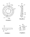
- FTGs. 2 and 3 illustrate a compressor rotor disc without compressor blades mounted thereon.
- the compressor rotor disc includes a circular flange 202 that protrudes outward from a first circular face of the rotor adjacent an outer edge 200 of the rotor.
- the compressor rotor also includes a second circular flange 211 formed on the second opposite circular face of the disc adjacent the outer edge 200 of the rotor disc.
- This compressor rotor also includes a third circular flange 204 that protrudes outward from the first circular face and which is located radially inward of the first circular flange 202.
- a plurality of rotating compressor blades are mounted around the outer circumferential edge of each compressor rotor disc.
- a plurality of compressor rotors 110, 112, 114 are stacked together to form the inner portions of the compressor section.
- cavities 120, 122 are formed between adjacent compressor discs 110, 112, 114.
- the cavities formed between adjacent compressor rotor discs can help to cause thermal and pressure gradients develop between the various elements of the compressor section. Those thermal and pressure gradients can negatively impact the life and performance of the compressor section and the turbine engine. The thermal gradients can induce stress in the elements of the compressor and negatively impact the clearances of the compressor rotating blades 130, 132, 134 and the stator vanes 140, 142, 144.
- one or more ventilation slots 210 may be cut in the circular flanges 202, 211 of the compressor rotor discs.
- the ventilation slots allow air or gas to freely flow back and forth between the cavities formed between adjacent compressor rotor discs and the areas located radially outward of the cavities.
- the ventilation slots can take the form of elongated depressions that are formed or cut into the circular flanges 202, 211.
- FIG. 2 shows that a longitudinal axis of the ventilation slots 210 extend in a radial direction of the disc-shaped compressor rotor disc.
- the cross-sectional view provided in FIG. 3 illustrates that the ventilation slots 210 are depressions formed or cut into the circular flanges 202, 211.
- FIG. 4 which provides a top view of a portion of the outer edge of a compressor rotor discs, illustrates that the ventilation slot 210 can have a semi-circular shape.
- FIG. 5 provides a perspective view of a portion of a compressor rotor which also illustrates a ventilation slot 210 formed in a circular flange 202 of the rotor.
- the ventilation slot 210 has a semi-circular shape, and a longitudinal axis of the ventilation slot 210 extends in a radial direction of the disc-shaped rotor disc.
- FIG. 2 includes two ventilation slots 210, alternate embodiments could have only a single ventilation slot, or more than two ventilation slots.
- FIG. 6 illustrates an embodiment having four ventilation slots 210.
- FIG. 7 illustrates another alternate embodiment having three ventilation slots 210.
- Other embodiments could have more than four ventilation slots.
- the ventilation slots 210 are located substantially symmetrically around the circumference of the circular flange 202.
- the ventilation slots could be located asymmetrically around the circumference of the compressor rotor disc.
- a compressor section of a turbine engine could be formed such that each compressor rotor disc has ventilation slots in a circular flange on only one side face of the rotor disc.
- the ventilation slots will ensure that the cavities formed between each adjacent pair of discs will be vented to the area radially outward of the cavities.
- two different types of compressor discs could alternate with one another in a stack of rotors.
- the first type of compressor rotor would have no ventilation slots.
- the second type of rotor would have ventilation slots located in the circular flanges located on both side faces. This arrangement would also ensure that the cavities formed between each adjacent pair of rotors will be vented to the area radially outward of the cavities.
- the number and size of the ventilation slots can be based on the volume of air that is expected to aspirate into or out of a cavity during startup or shutdown of a turbine engine.
- the volume of airflow may be based on the cavity size, the location of the cavity in the compressor, the anticipated cavity surface temperatures, and the flow path of air or gas through the compressor. Thus, all of these factors could influence the number and location of the ventilation slots.
- Ventilerly designed ventilation slots will improve rotor life by reducing transient thermal and pressure gradients experienced by different portions of the compressor, and as between adjacent discs.
- the ventilation slots will also improve compressor efficiency by minimizing purged regions within the compressor.
- Providing ventilation slots is also expected to improve the predictability of rotor metal temperatures as compared to compressor rotors lacking ventilation slots. Further, upon startup and shutdown, the provision of ventilation slots is expected to reduce the time required before all elements of the compressor reach a stable, steady state operating condition.
- FIGS. 2-5 illustrate ventilation slots having an elongated semicircular shape
- the ventilation slots could have a variety of other shapes.
- FIG. 8 shows an embodiment where a ventilation slot 210 is still rounded, but where the radially inward end of the ventilation slot is larger than the radially outward end of the ventilation slot 210.
- FIG. 9 illustrates a ventilation slot 210 having a square or rectangular profile.
- FIG. 10 illustrates a ventilation slot with a rectangular profile, but where the radially inward end of the ventilation slot 210 has a larger width than the radially outward end of the ventilation slot.
- FIG. 11 illustrates an embodiment where the radially inward end of the ventilation 210 slot has a smaller width than the radially outward end.
- FIG. 12 illustrates an embodiment where the ventilation slot 210 has a V-shaped profile.
- FIG. 13 illustrates a V-shaped ventilation slot 210 where the radially inward end is larger than the radially outward end.
- FIG. 14 illustrates a V-shaped ventilation slot 210 wherein the radially inward end of the V-shaped slot is smaller than the radially outward end.
- FIGS. 8-14 illustrate various alternatives, the ventilation slots could take on any other shape that still allows air or gases to aspirate into and out of the cavities formed between adjacent compressor rotor discs.
- the ventilation slots could take the form of holes, channels or passageways that pass through a circular flange from the radially inner side of the flange to the radially outer side of the flange.
- FIG. 15 illustrates an embodiment where a cylindrical ventilation slot 210 is bored though the circular flange 202 between the inner and outer faces of the circular flange 202.
- FIG. 16 illustrates another embodiment where a similar rectangular-shaped ventilation slot 210 is formed in a circular flange 202.
- some embodiments may have ventilation slots formed in the circular flanges formed on both side faces of the compressor rotor.
- the ventilation slots may be mirror images of each other on both side faces.
- the ventilation slots located in the circular flange on the first side face of the compressor rotor may be circumferentially offset from the ventilation slots located on the circular flange on the second side face of the rotor.
- a greater number of ventilation slots may be provided on a first face of the compressor rotor than on the second face of the rotor.
Landscapes
- Engineering & Computer Science (AREA)
- Mechanical Engineering (AREA)
- General Engineering & Computer Science (AREA)
- Structures Of Non-Positive Displacement Pumps (AREA)
Abstract
A turbine engine includes a plurality of compressor rotors that include ventilation slots (210) to vent the spaces between adjacent compressor rotors. Each compressor rotor is formed from a flat disk of material having first and second circular faces. A circular ridge (202,204) of material protrudes outward from the one of the circular faces of the disc adjacent an outer edge (200) of the disc. The ventilation slots (210) are formed in the circular ridge (202,204) of material. Each ventilation slot (210) is a depression in the circular ridge (202,204) of material, the depression having a longitudinal axis that extends substantially in a radial direction of the disc (210). A corresponding manufacturing method is also provided.


Description
- The invention relates to rotors used in the compressor of a gas turbine engine.
- The compressor section of a gas turbine engine used in power generation applications typically includes a plurality of disc-shaped compressor rotors which abut one another. A plurality of rotating compressor blades extend radially outward from the outer circumferential edge of each of the compressor rotors. Each compressor rotor is typically shaped such that circumferential flanges extend outward from both circular faces of the disc, the circumferential flanges being located adjacent the outer edge of the disc.
- When plurality of compressor discs are stacked together to form the compressor section of a gas turbine engine, the circumferential flanges of adjacent compressor rotors abut one another. As a result, a cavity is formed between each adjacent pair of compressor discs, the cavity being located radially inward of the mating circumferential flanges.
- Air or gases trapped in the cavity formed between adjacent compressor discs can act as a thermal insulator, which can result in temperature gradients between adjacent compressor discs. These temperature gradients can cause stress to develop between adjacent compressor discs. The temperature gradients can also negatively impact the tip clearance between the rotating compressor blades attached to the compressor discs and/or the compressor stator vanes.
- During startup or shutdown of a gas turbine engine, thermal gradients between the various elements of the compressor section are inevitable. The thermal insulating effect of the air or gases trapped in the cavities between adjacent compressor rotor discs can extend the time that those thermal gradients exist, as well as increase the stress on the components of the compressor section, and possibly negatively impacting the rotor blade and/or stator vane clearances for an extended period of time.
- In addition, when there is a temperature difference between a cavity located between adjacent compressor rotor discs and an area radially outward of the cavity, it is possible for a pressure gradient to develop between the cavities and the area radially outward of the cavities. This pressure gradient can also negatively impact compressor and turbine performance.
- In one aspect, the present invention resides in a compressor rotor for a turbine engine that includes a disc of material having first and second circular faces, and a circular flange that protrudes outward from the first circular face of the disc adjacent an outer edge of the disc. At least one ventilation slot is located in the circular flange, the at least one ventilation slot comprising a depression in the circular flange, the depression having a longitudinal axis that extends substantially in a radial direction of the disc. The disc may also include a second circular flange that protrudes outward from the second circular face of the disc adjacent an outer edge of the disc, where at least one ventilation slot is located in the second circular flange, the at least one ventilation slot comprising a depression in the second circular flange, the depression having a longitudinal axis that extends substantially in a radial direction of the disc.
- In another aspect, the invention resides in a method of manufacturing a compressor rotor for a turbine engine. The method includes forming a disc of material having first and second circular faces and a circular flange that protrudes outward from the first circular face of the disc adjacent an outer edge of the disc. The method also includes forming at least one ventilation slot in the circular flange, the at least one ventilation slot comprising a depression in the circular flange, the depression having a longitudinal axis that extends substantially in a radial direction of the disc.brief description of the drawings.
- Embodiments of the present invention will now be described, by way of example only, with reference to the accompanying drawings in which:
-
FIGURE 1 is a partial cross-sectional view of the compressor section of a turbine engine; -
FIGURE 2 is a plan view of a first embodiment of a compressor rotor disc of a turbine engine; -
FIGURE 3 is a cross-sectional view of the rotor illustrated inFigure 2 taken along section line III-III; -
FIGURE 4 is a top view of a portion of an edge of a compressor rotor disc of a turbine engine; -
FIGURE 5 is a perspective view of a portion of a compressor rotor disc of a turbine engine; -
FIGURE 6 is a plan view of an alternate compressor rotor disc of a turbine engine; -
FIGURE 7 is a plan view of another alternate compressor rotor disc of a turbine engine; -
FIGURE 8 is a perspective view of a portion of an alternate compressor rotor disc of a turbine engine; -
FIGURE 9 is a perspective view of a portion of an alternate compressor rotor disc of a turbine engine; -
FIGURE 10 is a perspective view of a portion of an alternate compressor rotor disc of a turbine engine; -
FIGURE 11 is a perspective view of a portion of an alternate compressor rotor disc of a turbine engine; -
FIGURE 12 is a perspective view of a portion of an alternate compressor rotor disc of a turbine engine; -
FIGURE 13 is a perspective view of a portion of an alternate compressor rotor disc of a turbine engine; -
FIGURE 14 is a perspective view of a portion of an alternate compressor rotor disc of a turbine engine -
FIGURE 15 is a perspective view of a portion of an alternate compressor rotor disc of a turbine engine; and -
FIGURE 16 is a perspective view of a portion of an alternate compressor rotor disc of a turbine engine. - The following detailed description of preferred embodiments refers to the accompanying drawings, which illustrate specific embodiments of the invention. Other embodiments having different structures and operations do not depart from the scope of the present invention.
-
FIG. 1 illustrates the compressor section of a typical turbine engine which may be used in a power generating facility. The compressor section includes aninlet 102 which receives a flow of inlet air. The compressor section also includes alternating rows ofstator vanes compressor blades compressor blades compressor rotor discs - FTGs. 2 and 3 illustrate a compressor rotor disc without compressor blades mounted thereon. The compressor rotor disc includes a
circular flange 202 that protrudes outward from a first circular face of the rotor adjacent anouter edge 200 of the rotor. The compressor rotor also includes a secondcircular flange 211 formed on the second opposite circular face of the disc adjacent theouter edge 200 of the rotor disc. This compressor rotor also includes a thirdcircular flange 204 that protrudes outward from the first circular face and which is located radially inward of the firstcircular flange 202. - As illustrated in
FIG. 1 a plurality of rotating compressor blades are mounted around the outer circumferential edge of each compressor rotor disc. As also illustrated inFIG. 1 , a plurality ofcompressor rotors cavities adjacent compressor discs - The cavities formed between adjacent compressor rotor discs can help to cause thermal and pressure gradients develop between the various elements of the compressor section. Those thermal and pressure gradients can negatively impact the life and performance of the compressor section and the turbine engine. The thermal gradients can induce stress in the elements of the compressor and negatively impact the clearances of the
compressor rotating blades stator vanes - To help prevent thermal and pressure gradients from developing, one or
more ventilation slots 210 may be cut in thecircular flanges - The ventilation slots can take the form of elongated depressions that are formed or cut into the
circular flanges FIG. 2 shows that a longitudinal axis of theventilation slots 210 extend in a radial direction of the disc-shaped compressor rotor disc. The cross-sectional view provided inFIG. 3 illustrates that theventilation slots 210 are depressions formed or cut into thecircular flanges FIG. 4 , which provides a top view of a portion of the outer edge of a compressor rotor discs, illustrates that theventilation slot 210 can have a semi-circular shape. -
FIG. 5 provides a perspective view of a portion of a compressor rotor which also illustrates aventilation slot 210 formed in acircular flange 202 of the rotor. Theventilation slot 210 has a semi-circular shape, and a longitudinal axis of theventilation slot 210 extends in a radial direction of the disc-shaped rotor disc. - Although the embodiment illustrated in
FIG. 2 includes twoventilation slots 210, alternate embodiments could have only a single ventilation slot, or more than two ventilation slots.FIG. 6 illustrates an embodiment having fourventilation slots 210.FIG. 7 illustrates another alternate embodiment having threeventilation slots 210. Other embodiments could have more than four ventilation slots. - In the embodiments illustrated in
FIGs. 2 ,6 and 7 , theventilation slots 210 are located substantially symmetrically around the circumference of thecircular flange 202. However, in alternate embodiments, the ventilation slots could be located asymmetrically around the circumference of the compressor rotor disc. - A compressor section of a turbine engine could be formed such that each compressor rotor disc has ventilation slots in a circular flange on only one side face of the rotor disc. When a plurality of such compressor rotor discs are stacked together, the ventilation slots will ensure that the cavities formed between each adjacent pair of discs will be vented to the area radially outward of the cavities.
- Alternatively, two different types of compressor discs could alternate with one another in a stack of rotors. The first type of compressor rotor would have no ventilation slots. The second type of rotor would have ventilation slots located in the circular flanges located on both side faces. This arrangement would also ensure that the cavities formed between each adjacent pair of rotors will be vented to the area radially outward of the cavities.
- When a turbine engine having compressor rotor discs with ventilation slots is first put into operation, the various elements of the compressor section will all begin to heat up. Because the ventilation slots allow air or gases to flow into and out of the cavities between adjacent compressor rotor discs, no pressure gradients are likely to develop. Also, if one region becomes hotter than another region, the pressure of the gas in the hotter region will increase, which will cause gas from the hotter region to flow into an adjacent cooler (lower pressure) region. This movement of gas from a hotter region to a cooler region will help to reduce temperature gradients between different regions of the compressor section. And, as noted above, this will help to reduce thermally induced stress. This same process also occurs upon shutdown of the turbine engine when different regions will cool at different rates.
- The number and size of the ventilation slots can be based on the volume of air that is expected to aspirate into or out of a cavity during startup or shutdown of a turbine engine. The volume of airflow, in turn, may be based on the cavity size, the location of the cavity in the compressor, the anticipated cavity surface temperatures, and the flow path of air or gas through the compressor. Thus, all of these factors could influence the number and location of the ventilation slots.
- Properly designed ventilation slots will improve rotor life by reducing transient thermal and pressure gradients experienced by different portions of the compressor, and as between adjacent discs. The ventilation slots will also improve compressor efficiency by minimizing purged regions within the compressor. Providing ventilation slots is also expected to improve the predictability of rotor metal temperatures as compared to compressor rotors lacking ventilation slots. Further, upon startup and shutdown, the provision of ventilation slots is expected to reduce the time required before all elements of the compressor reach a stable, steady state operating condition.
- Although
FIGS. 2-5 illustrate ventilation slots having an elongated semicircular shape, the ventilation slots could have a variety of other shapes. For example,FIG. 8 shows an embodiment where aventilation slot 210 is still rounded, but where the radially inward end of the ventilation slot is larger than the radially outward end of theventilation slot 210. -
FIG. 9 illustrates aventilation slot 210 having a square or rectangular profile.FIG. 10 illustrates a ventilation slot with a rectangular profile, but where the radially inward end of theventilation slot 210 has a larger width than the radially outward end of the ventilation slot. Conversely,FIG. 11 illustrates an embodiment where the radially inward end of theventilation 210 slot has a smaller width than the radially outward end. -
FIG. 12 illustrates an embodiment where theventilation slot 210 has a V-shaped profile.FIG. 13 illustrates a V-shapedventilation slot 210 where the radially inward end is larger than the radially outward end. Conversely,FIG. 14 illustrates a V-shapedventilation slot 210 wherein the radially inward end of the V-shaped slot is smaller than the radially outward end. - Although
FIGS. 8-14 illustrate various alternatives, the ventilation slots could take on any other shape that still allows air or gases to aspirate into and out of the cavities formed between adjacent compressor rotor discs. For example, the ventilation slots could take the form of holes, channels or passageways that pass through a circular flange from the radially inner side of the flange to the radially outer side of the flange.FIG. 15 illustrates an embodiment where acylindrical ventilation slot 210 is bored though thecircular flange 202 between the inner and outer faces of thecircular flange 202.FIG. 16 illustrates another embodiment where a similar rectangular-shapedventilation slot 210 is formed in acircular flange 202. - As noted above, some embodiments may have ventilation slots formed in the circular flanges formed on both side faces of the compressor rotor. In these embodiments, the ventilation slots may be mirror images of each other on both side faces. Alternatively, although the same number of ventilation slots are provided on both side faces, the ventilation slots located in the circular flange on the first side face of the compressor rotor may be circumferentially offset from the ventilation slots located on the circular flange on the second side face of the rotor. In still other embodiments, a greater number of ventilation slots may be provided on a first face of the compressor rotor than on the second face of the rotor.
- The terminology used herein is for the purpose of describing particular embodiments only and is not intended to be limiting of the invention. As used herein, the singular forms "a", "an" and "the" are intended to include the plural forms as well, unless the context clearly indicates otherwise. It will be further understood that the terms "comprises" and/or "comprising," when used in this specification, specify the presence of stated features, integers, steps, operations, elements, and/or components, but do not preclude the presence or addition of one or more other features, integers, steps, operations, elements, components, and/or groups thereof.
- While the invention has been described in connection with what is presently considered to be the most practical and preferred embodiment, it is to be understood that the invention is not to be limited to the disclosed embodiment, but on the contrary, is intended to cover various modifications and equivalent arrangements included within the spirit and scope of the appended claims.
Claims (15)
- A compressor rotor for a turbine engine, comprising:a disc (110,112,114) of material having first and second circular faces;a circular flange (202) that protrudes outward from the first circular face of the disc (110,112,114) adjacent an outer edge (200) of the disc; andat least one ventilation slot (210) located in the circular flange (202), the at least one ventilation slot (210) having a longitudinal axis that extends substantially in a radial direction of the disc (110,112,114).
- The compressor rotor of claim 1, wherein the at least one ventilation slot (210) comprises first and second ventilation slots that are formed on opposite sides of the circular flange (202).
- The compressor rotor of claim 1, wherein the at least one ventilation slot (210) comprises a plurality of ventilation slots.
- The compressor rotor of claim 3, wherein the plurality of ventilation slots (210) are located substantially symmetrically around a circumference of the circular flange. (202)
- The compressor rotor of claim 1, wherein a radially inner end of the at least one ventilation slot (210) is larger than a radially outer end of the at least one ventilation slot.
- The compressor rotor of claim 1, wherein the at least one ventilation slot (210) comprises a depression formed on an outer surface of the circular flange (202).
- The compressor rotor of claim 8, wherein the at least one ventilation slot (210) has one of a semi-circular profile, a V-shaped profile or a square or rectangular shaped profile.
- The compressor rotor of claim 1, wherein the at least one ventilation slot (210) comprises a passageway that extends through the circular flange (202) from a radially inner surface of the circular flange (202) to a radially outer surface of the circular flange (202).
- The compressor rotor of claim 8, wherein the size of the passageway varies along a length of the passageway.
- The compressor rotor of any preceding claim, wherein the circular flange (202) on the first circular face comprises a first circular flange (202), the compressor rotor further comprising:a second circular flange (211) that protrudes outward from the second circular face of the disc a (110,112,114) adjacent an outer edge of the disc (110,112,114); andat least one ventilation slot (210) located in the second circular flange (211), the at least one ventilation slot (210) having a longitudinal axis that extends substantially in a radial direction of the disc (110,112,114).
- The compressor rotor of claim 10, wherein the at least one ventilation slot (210) located in the first circular flange (202) is offset circumferentially from the at least one ventilation slot (210) located in the second circular flange (211).
- A method of manufacturing a compressor rotor for a turbine engine, comprising:forming a disc (110,112,114) of material having first and second circular faces and a circular flange (202) that protrudes outward from the first circular face of the disc (110,112,114) adjacent an outer edge of the disc (110,112,114); andforming at least one ventilation slot (210) in the circular flange (202), the at least one ventilation slot (210) having a longitudinal axis that extends substantially in a radial direction of the disc (110,112,114).
- The method of claim 12, wherein the step of forming at least one ventilation slot (210) comprises forming a plurality of ventilation slots (210) in the circular flange (202).
- The method of claim 13, further comprising forming the plurality of ventilation slots symmetrically around the circumference of the circular flange.
- The method of any of claims 12 to 14, wherein the circular flange on the first circular face of the disc comprises a first circular flange, wherein step of forming the disc further comprising forming a second circular flange that protrudes outward from the second circular face of the disc adjacent the outer edge of the disc, and further comprising forming at least one ventilation slot in the second circular flange, the at least one ventilation slot having a longitudinal axis that extends substantially in a radial direction of the disc.
Applications Claiming Priority (1)
| Application Number | Priority Date | Filing Date | Title |
|---|---|---|---|
| US13/163,966 US20120321441A1 (en) | 2011-06-20 | 2011-06-20 | Ventilated compressor rotor for a turbine engine and a turbine engine incorporating same |
Publications (1)
| Publication Number | Publication Date |
|---|---|
| EP2538021A2 true EP2538021A2 (en) | 2012-12-26 |
Family
ID=46245971
Family Applications (1)
| Application Number | Title | Priority Date | Filing Date |
|---|---|---|---|
| EP12172088A Withdrawn EP2538021A2 (en) | 2011-06-20 | 2012-06-14 | Ventilated compressor rotor for a turbine engine and corresponding manufacturing method |
Country Status (3)
| Country | Link |
|---|---|
| US (1) | US20120321441A1 (en) |
| EP (1) | EP2538021A2 (en) |
| CN (1) | CN102840144A (en) |
Cited By (1)
| Publication number | Priority date | Publication date | Assignee | Title |
|---|---|---|---|---|
| WO2014197474A1 (en) * | 2013-06-05 | 2014-12-11 | Siemens Aktiengesellschaft | Rotor disc with fluid removal channels to enhance life of spindle bolt |
Families Citing this family (1)
| Publication number | Priority date | Publication date | Assignee | Title |
|---|---|---|---|---|
| FR3062415B1 (en) * | 2017-02-02 | 2019-06-07 | Safran Aircraft Engines | ROTOR OF TURBINE TURBINE ENGINE WITH VENTILATION BY LAMINATION |
Family Cites Families (14)
| Publication number | Priority date | Publication date | Assignee | Title |
|---|---|---|---|---|
| BE431387A (en) * | 1936-07-01 | |||
| US2452782A (en) * | 1945-01-16 | 1948-11-02 | Power Jets Res & Dev Ltd | Construction of rotors for compressors and like machines |
| GB612097A (en) * | 1946-10-09 | 1948-11-08 | English Electric Co Ltd | Improvements in and relating to the cooling of gas turbine rotors |
| DE2514208A1 (en) * | 1975-04-01 | 1976-10-14 | Kraftwerk Union Ag | DISC DESIGN GAS TURBINE |
| US4021138A (en) * | 1975-11-03 | 1977-05-03 | Westinghouse Electric Corporation | Rotor disk, blade, and seal plate assembly for cooled turbine rotor blades |
| GB2081392B (en) * | 1980-08-06 | 1983-09-21 | Rolls Royce | Turbomachine seal |
| JPS5896105A (en) * | 1981-12-03 | 1983-06-08 | Hitachi Ltd | Air-leakage prevention rotor at spacer top |
| FR2732405B1 (en) * | 1982-03-23 | 1997-05-30 | Snecma | DEVICE FOR COOLING THE ROTOR OF A GAS TURBINE |
| US5340274A (en) * | 1991-11-19 | 1994-08-23 | General Electric Company | Integrated steam/air cooling system for gas turbines |
| KR100389990B1 (en) * | 1995-04-06 | 2003-11-17 | 가부시끼가이샤 히다치 세이사꾸쇼 | Gas turbine |
| JP3621523B2 (en) * | 1996-09-25 | 2005-02-16 | 株式会社東芝 | Gas turbine rotor blade cooling system |
| US6065282A (en) * | 1997-10-29 | 2000-05-23 | Mitsubishi Heavy Industries, Ltd. | System for cooling blades in a gas turbine |
| US5984636A (en) * | 1997-12-17 | 1999-11-16 | Pratt & Whitney Canada Inc. | Cooling arrangement for turbine rotor |
| JP5129633B2 (en) * | 2008-03-28 | 2013-01-30 | 三菱重工業株式会社 | Cover for cooling passage, method for manufacturing the cover, and gas turbine |
-
2011
- 2011-06-20 US US13/163,966 patent/US20120321441A1/en not_active Abandoned
-
2012
- 2012-06-14 EP EP12172088A patent/EP2538021A2/en not_active Withdrawn
- 2012-06-20 CN CN2012102109584A patent/CN102840144A/en active Pending
Non-Patent Citations (1)
| Title |
|---|
| None |
Cited By (2)
| Publication number | Priority date | Publication date | Assignee | Title |
|---|---|---|---|---|
| WO2014197474A1 (en) * | 2013-06-05 | 2014-12-11 | Siemens Aktiengesellschaft | Rotor disc with fluid removal channels to enhance life of spindle bolt |
| US9951621B2 (en) | 2013-06-05 | 2018-04-24 | Siemens Aktiengesellschaft | Rotor disc with fluid removal channels to enhance life of spindle bolt |
Also Published As
| Publication number | Publication date |
|---|---|
| US20120321441A1 (en) | 2012-12-20 |
| CN102840144A (en) | 2012-12-26 |
Similar Documents
| Publication | Publication Date | Title |
|---|---|---|
| CN105026691B (en) | Gas turbine rotor blades and gas turbine rotor | |
| EP3155233B1 (en) | Gas turbine engine with rotor centering cooling system in an exhaust diffuser | |
| US11732593B2 (en) | Flared central cavity aft of airfoil leading edge | |
| US8167559B2 (en) | Turbine vane for a gas turbine engine having serpentine cooling channels within the outer wall | |
| US9121298B2 (en) | Finned seal assembly for gas turbine engines | |
| EP2375003B1 (en) | Axially-oriented cellular seal structure for turbine shrouds | |
| US10119406B2 (en) | Blade with stress-reducing bulbous projection at turn opening of coolant passages | |
| US11891920B2 (en) | Turbine stator vane and gas turbine | |
| US10605090B2 (en) | Intermediate central passage spanning outer walls aft of airfoil leading edge passage | |
| US20130142667A1 (en) | Turbine blade and gas turbine having the same | |
| US9816389B2 (en) | Turbine rotor blades with tip portion parapet wall cavities | |
| EP3551851B1 (en) | Turbine element | |
| EP3483392A1 (en) | Gas turbine engines with improved airfoil dust removal | |
| US7207775B2 (en) | Turbine bucket with optimized cooling circuit | |
| US10934846B2 (en) | Turbine rotor comprising a ventilation spacer | |
| EP2538021A2 (en) | Ventilated compressor rotor for a turbine engine and corresponding manufacturing method | |
| CN108386239A (en) | Turbogenerator with the extension led in cushion chamber | |
| CN107366554B (en) | Internal ribs with defined concave curvature for the airfoil | |
| US11499430B2 (en) | Turbine rotor blade, turbine, and tip clearance measurement method | |
| EP4189215B1 (en) | Guide vane for a gas turbine engine | |
| US20220220856A1 (en) | Turbine rotor blade and gas turbine |
Legal Events
| Date | Code | Title | Description |
|---|---|---|---|
| PUAI | Public reference made under article 153(3) epc to a published international application that has entered the european phase |
Free format text: ORIGINAL CODE: 0009012 |
|
| AK | Designated contracting states |
Kind code of ref document: A2 Designated state(s): AL AT BE BG CH CY CZ DE DK EE ES FI FR GB GR HR HU IE IS IT LI LT LU LV MC MK MT NL NO PL PT RO RS SE SI SK SM TR |
|
| AX | Request for extension of the european patent |
Extension state: BA ME |
|
| STAA | Information on the status of an ep patent application or granted ep patent |
Free format text: STATUS: THE APPLICATION IS DEEMED TO BE WITHDRAWN |
|
| 18D | Application deemed to be withdrawn |
Effective date: 20160105 |