EP2537706A1 - Internal handle of a vehicle cabin, in particular of an industrial or commercial vehicle - Google Patents
Internal handle of a vehicle cabin, in particular of an industrial or commercial vehicle Download PDFInfo
- Publication number
- EP2537706A1 EP2537706A1 EP11171023A EP11171023A EP2537706A1 EP 2537706 A1 EP2537706 A1 EP 2537706A1 EP 11171023 A EP11171023 A EP 11171023A EP 11171023 A EP11171023 A EP 11171023A EP 2537706 A1 EP2537706 A1 EP 2537706A1
- Authority
- EP
- European Patent Office
- Prior art keywords
- handle
- container
- vehicle
- vehicle cabin
- cabin
- Prior art date
- Legal status (The legal status is an assumption and is not a legal conclusion. Google has not performed a legal analysis and makes no representation as to the accuracy of the status listed.)
- Granted
Links
Images


Classifications
-
- B—PERFORMING OPERATIONS; TRANSPORTING
- B60—VEHICLES IN GENERAL
- B60N—SEATS SPECIALLY ADAPTED FOR VEHICLES; VEHICLE PASSENGER ACCOMMODATION NOT OTHERWISE PROVIDED FOR
- B60N3/00—Arrangements or adaptations of other passenger fittings, not otherwise provided for
- B60N3/10—Arrangements or adaptations of other passenger fittings, not otherwise provided for of receptacles for food or beverages, e.g. refrigerated
- B60N3/102—Arrangements or adaptations of other passenger fittings, not otherwise provided for of receptacles for food or beverages, e.g. refrigerated storable or foldable in a non-use position
-
- B—PERFORMING OPERATIONS; TRANSPORTING
- B60—VEHICLES IN GENERAL
- B60N—SEATS SPECIALLY ADAPTED FOR VEHICLES; VEHICLE PASSENGER ACCOMMODATION NOT OTHERWISE PROVIDED FOR
- B60N3/00—Arrangements or adaptations of other passenger fittings, not otherwise provided for
- B60N3/02—Arrangements or adaptations of other passenger fittings, not otherwise provided for of hand grips or straps
- B60N3/023—Arrangements or adaptations of other passenger fittings, not otherwise provided for of hand grips or straps movable
Definitions
- the present invention refers to the field of internal furnishings of industrial and commercial vehicles. In particular it refers to an internal handle of a vehicle cabin.
- Retractable tables and food containers are dimensioned and arranged so that they do not clutter up the vehicle cabin.
- a solution known is, for example, to arrange a food container, possibly refrigerated, under a bed arranged behind the driver's seat, transversal to the direction of travel of the vehicle.
- Such container is equipped with sliding guides, or rails, in order to move it forward, towards the direction of travel, and access to its inside, and to move it back to the retracted position, even completely under the bed, when it is not necessary to access to its inside.
- the aim of the present invention is to provide a handle suitable for at least a further function in addition to the handle function, in order to limit the number of components inside the vehicle cabin, but without limiting the comfort functionalities required and without increasing the bulk of the components, obtaining more free space inside the vehicle cabin.
- the handle can move from an open position to a closed position.
- the lying plane of the middle grip part, with the handle in the open position is parallel to a surface comprised by said part of the vehicle cabin to which the handle is suitable to be hinged.
- the flanges may be retroverted, so that in open position the lying plane of the middle grip part is parallel to said surface of the cabin.
- the handle indicated by the present invention has a twofold function: defining a retractable handle and defining a bottle holder, comprised in the space between the handle and the part of the vehicle cabin to which the handle is suitable to be associated.
- the middle grip part may comprise a shaped element in order to define one or more bottle holder seats, so that it is not necessary that said lying plane is perfectly parallel to said surface of the vehicle cabin when the handle is open.
- the handle is ready to be applied to different internal parts of the cabin and to different vehicle containers.
- such container is a food container and preferably it is refrigerated or it is a fridge.
- Another aim of the present invention is to indicate a vehicle arrangement suitable to minimize the internal bulk and to maximize the comfort inside the vehicle cabin, in particular of an industrial or commercial vehicle.
- a handle according to the present invention is substantially U-shaped with a middle grip part 10 longitudinally shaped, whose opposite ends 10b, 10c are connected to connection flanges 11 and 12 in a substantially parallel way between each other.
- the connection flanges are themselves longitudinally shaped and lie on planes perpendicular to a lying plane P defined by the middle grip part 10.
- the middle grip part 10 defines the lying plane P and that the connection flanges are retroverted with respect to such plane P, namely they are not perpendicular to the lying plane P, with a deviation angle with respect to the direction perpendicular to P comprised preferably between 1° and 50°.
- such deviation may be varied so that when the handle is in open position, such lying plane is parallel to a vehicle surface 21 opposite to such middle grip part 10.
- a space for holding bottles 30 is defined.
- the flanges extend accordingly with each other, and their respective free ends 10b and 11b are arched in the aforementioned parallel planes where the flanges lie.
- the handle that is object of the present invention is similar to eyeglass frames with their respective side-pieces.
- the free ends 10b and 11b are intended to be hinged to the internal container 20 of a vehicle cabin 100, with a common axis of rotation X, so that the handle 1 may rotate around the axis X between an open position of use (see figures 3, 4 , 6, 7 ) and a closed or retracted position (see figures 2 and 5 ), wherein the middle grip part 10 of the handle overlaps a surface 21 of the internal container 20 of the vehicle to which the handle is hinged.
- Such part of the vehicle may be fixed or movable.
- the handle 1 has the main function to allow the grip and the movement of the movable internal container 20 of the vehicle cabin 100.
- the handle 1 When the internal container 20 is fixed, for example when being part of the vehicle dashboard, the handle 1 performs the task of holding a passenger of the vehicle cabin 100.
- the handle as such, must have characteristics of solidity suitable to hold a passenger or to move the container 20. Such characteristics, obviously, are different from a common bottle holder dimensioned to just carry bottles and not to take higher stresses.
- the container 20 may have substantially any shape, provided that it has two parallel surfaces, to which the flanges 11 and 12 and a surface 21 can be hinged, belonging to a bundle of planes which share a straight line perpendicular to said two surfaces S.
- a further function of the handle is to contain one or two standard size 1.5L or 2L bottles 30 within the space comprised between the handle 1 itself, in open position, and said surface 21 of the internal container 20 of the vehicle cabin 100.
- the handle when closed it does not clutter further the inside of the vehicle cabin 100.
- Flanges 11 and 12 are retroverted and their length is such that, when a bottle is inserted between the handle 1 and the internal container 20 of the vehicle cabin, the middle grip part 10 corresponds to a middle part at level with the bottle.
- the projection h of the flanges 11 and 12 on the lying plane P identified by the middle grip part 10 corresponds to about half of the height of a standard size 1.5L or 2L bottle.
- the handle 1 it is appropriate to assemble the handle 1 to the internal container 20 of the vehicle cabin 100, so that there is not too much play between a bottle 30, the handle 1 and the internal container 20.
- the internal area 10a of the middle part 10 of the handle 1, namely the part comprised between the flanges 11 and 12, is preferably provided with a shaped element 15 which defines, for example, two bottle seats 18 and 19 in correspondence of the ends 10b and 10c of the middle part 10, namely where such ends 10b and 10c are connected with the flanges 11 and 12.
- such seats are suitable to keep the bottles spaced, so that a middle portion of the part 10 stays empty, facilitating the grip of the handle 1, in order to avoid any movement of the bottles 30 during bends or bumps of the road.
- the flanges 11 and 12 and the middle part 10 may be monolithic between each other, preferably the shaped element 15 is optionally realized separately and connected to the handle by glueing, by welding, by a fixed joint, or by any other method available to the person skilled in the art. This occurs because the shaped element is preferably made of a resilient material, such as vulcanized rubber or India rubber and the like.
- the handle may be made of a more rigid and robust material, from plastic such as polyethylene or ABS to metals and alloys, such as for example aluminium.
- bottles may be inserted and blocked by the shaped element 15, without necessarily having to rest their lower part on another surface.
- an intermediate area of the flanges 11 and 12 comprise an arching which makes the flanges 11 and 12 reciprocally introverted, namely convergent toward each other.
- arching makes the flanges elastic and allows to apply the same handle to containers or vehicle dashboards having slightly different size or to pairs of generic flat surfaces being parallel to each other at slightly different distances.
- the ends 11b and 12b of the flanges 11 and 12 are preferably hinged to the internal container 20 by means of bolts comprising limit stop means, in order to limit the opening of the handle.
- the handle that is object of the present invention is preferably applied to a vehicle food container 20, preferably refrigerated, or a fridge.
- the vehicle cabin comprises at least a seat 40 turned towards the direction of travel and a bed 50 placed transversally with respect to the direction of travel of the vehicle, in a rear position with respect to the seat 40.
- the food container 20 is placed under the bed 50 and comprises sliding means, such as guides or rails, etc. which allow a forward or backward movement according to the longitudinal axis of the vehicle, according to the direction of travel.
- the handle 1 then, allows to take the food container 20 easily and to hold one or two standard size 1.5L or 2L bottles. When there are no bottles the handle may be raised in closed position, as shown in figures 2 and 5 , overlapping the portion 10a on the surface 21 of the container 20, thus disappearing and minimizing its bulk.
- the food container 20 lies on the floor 101 of the vehicle cabin 100. Preferably it is slidingly constrained to the floor of the cabin.
- the handle 1 may be assembled to the food container 20
- a single component such as the present handle 1 may advantageously be connected to pre-existing internal parts of a cabin in order to allow to hold a passenger, or to seize a movable part of the cabin and even to hold one or two bottles 30 when in open position.
- the handle When in closed position, thus raised, the handle remarkably reduces its bulk and keeps the internal space of the vehicle cabin substantially unchanged.
Landscapes
- Engineering & Computer Science (AREA)
- Transportation (AREA)
- Mechanical Engineering (AREA)
- Physics & Mathematics (AREA)
- Thermal Sciences (AREA)
- Passenger Equipment (AREA)
Abstract
Description
- The present invention refers to the field of internal furnishings of industrial and commercial vehicles. In particular it refers to an internal handle of a vehicle cabin.
- Dimensioning vehicle furnishing, especially for industrial vehicles, is extremely complex, because it has to occupy little space, without penalizing comfort and functionality. Retractable tables and food containers are dimensioned and arranged so that they do not clutter up the vehicle cabin. A solution known is, for example, to arrange a food container, possibly refrigerated, under a bed arranged behind the driver's seat, transversal to the direction of travel of the vehicle. Such container is equipped with sliding guides, or rails, in order to move it forward, towards the direction of travel, and access to its inside, and to move it back to the retracted position, even completely under the bed, when it is not necessary to access to its inside.
- In such context it is complex to arrange handles, holders and furnishing which do not clutter the cabin up when not in use. It is even more complex to arrange parts that can perform more than one task in order to limit the number of components inside the vehicle cabin and their respective bulk.
- Therefore the aim of the present invention is to provide a handle suitable for at least a further function in addition to the handle function, in order to limit the number of components inside the vehicle cabin, but without limiting the comfort functionalities required and without increasing the bulk of the components, obtaining more free space inside the vehicle cabin.
- It is object of the present invention an internal handle of a vehicle cabin, in particular of an industrial or commercial vehicle, according to
claim 1. - The handle can move from an open position to a closed position. Preferably, the lying plane of the middle grip part, with the handle in the open position, is parallel to a surface comprised by said part of the vehicle cabin to which the handle is suitable to be hinged.
- Moreover, according to the assembly position of the handle with respect to the part of the vehicle cabin, the flanges may be retroverted, so that in open position the lying plane of the middle grip part is parallel to said surface of the cabin. Thus, advantageously, the handle indicated by the present invention has a twofold function: defining a retractable handle and defining a bottle holder, comprised in the space between the handle and the part of the vehicle cabin to which the handle is suitable to be associated.
- As an alternative, the middle grip part may comprise a shaped element in order to define one or more bottle holder seats, so that it is not necessary that said lying plane is perfectly parallel to said surface of the vehicle cabin when the handle is open.
- Moreover the handle is ready to be applied to different internal parts of the cabin and to different vehicle containers.
- It is also object of the present invention a movable container provided with an aforementioned handle according to claim 6.
- Preferably such container is a food container and preferably it is refrigerated or it is a fridge.
- Another aim of the present invention is to indicate a vehicle arrangement suitable to minimize the internal bulk and to maximize the comfort inside the vehicle cabin, in particular of an industrial or commercial vehicle.
- It is particular the object of the present invention a vehicle cabin and a respective industrial or commercial vehicle, as described more fully in the claims, which are an integral part of the present description.
- Further purposes and advantages of this invention will become clear from the following detailed description of a preferred embodiment and from the drawings that are attached hereto that are merely illustrative and not limitative, in which:
-
figure 1 shows a perspective view of a handle according to the present invention, -
figures 2, 3 and 4 show side views of an application of the handle offigure 1 at a vehicle food container; figures show the possible usage configurations of the handle, -
figures 5, 6 and 7 show perspective views corresponding respectively tofigures 2 - 4 , -
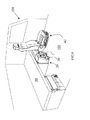
figure 8 show a perspective view in partial transparency of a vehicle cabin of an industrial or commercial vehicle comprising a food container equipped with the handle of the present invention according to the previous figures. - In the figures the same reference numbers and letters identify the same elements or components.
- With particular reference to
figure 1 , a handle according to the present invention is substantially U-shaped with amiddle grip part 10 longitudinally shaped, whoseopposite ends connection flanges middle grip part 10. According to the preferred alternative embodiment shown in the figures, comparingfigure 1 withfigures 2 - 4 , it can be seen that themiddle grip part 10 defines the lying plane P and that the connection flanges are retroverted with respect to such plane P, namely they are not perpendicular to the lying plane P, with a deviation angle with respect to the direction perpendicular to P comprised preferably between 1° and 50°. - As it will be explained below, such deviation may be varied so that when the handle is in open position, such lying plane is parallel to a
vehicle surface 21 opposite to suchmiddle grip part 10. Thus a space for holdingbottles 30 is defined. - In particular, the flanges extend accordingly with each other, and their respective
free ends - According to another aspect of the invention, the handle that is object of the present invention is similar to eyeglass frames with their respective side-pieces.
- The
free ends internal container 20 of avehicle cabin 100, with a common axis of rotation X, so that thehandle 1 may rotate around the axis X between an open position of use (seefigures 3, 4 ,6, 7 ) and a closed or retracted position (seefigures 2 and5 ), wherein themiddle grip part 10 of the handle overlaps asurface 21 of theinternal container 20 of the vehicle to which the handle is hinged. Such part of the vehicle may be fixed or movable. When theinternal container 20 of thevehicle cabin 100 is movable, thehandle 1 has the main function to allow the grip and the movement of the movableinternal container 20 of thevehicle cabin 100. - When the
internal container 20 is fixed, for example when being part of the vehicle dashboard, thehandle 1 performs the task of holding a passenger of thevehicle cabin 100. - It is evident that the handle as such, must have characteristics of solidity suitable to hold a passenger or to move the
container 20. Such characteristics, obviously, are different from a common bottle holder dimensioned to just carry bottles and not to take higher stresses. - In order to mount the handle in the vehicle cabin, it is essential that there are at least two surfaces S parallel between each other to which the
free ends flanges - Thus the
container 20 may have substantially any shape, provided that it has two parallel surfaces, to which theflanges surface 21 can be hinged, belonging to a bundle of planes which share a straight line perpendicular to said two surfaces S. - A further function of the handle is to contain one or two standard size 1.5L or
2L bottles 30 within the space comprised between thehandle 1 itself, in open position, and saidsurface 21 of theinternal container 20 of thevehicle cabin 100. - Advantageously when the handle is closed it does not clutter further the inside of the
vehicle cabin 100. -
Flanges handle 1 and theinternal container 20 of the vehicle cabin, themiddle grip part 10 corresponds to a middle part at level with the bottle. In other words, the projection h of theflanges middle grip part 10 corresponds to about half of the height of a standard size 1.5L or 2L bottle. - According to another aspect of the invention, it is appropriate to assemble the
handle 1 to theinternal container 20 of thevehicle cabin 100, so that there is not too much play between abottle 30, thehandle 1 and theinternal container 20. - In order to improve the adaptability of the handle to hold bottles having different shapes or profiles, limiting the aforementioned play, with particular reference to
figure 1 , theinternal area 10a of themiddle part 10 of thehandle 1, namely the part comprised between theflanges shaped element 15 which defines, for example, twobottle seats ends middle part 10, namely wheresuch ends flanges - Advantageously, such seats are suitable to keep the bottles spaced, so that a middle portion of the
part 10 stays empty, facilitating the grip of thehandle 1, in order to avoid any movement of thebottles 30 during bends or bumps of the road. - While the
flanges middle part 10 may be monolithic between each other, preferably theshaped element 15 is optionally realized separately and connected to the handle by glueing, by welding, by a fixed joint, or by any other method available to the person skilled in the art. This occurs because the shaped element is preferably made of a resilient material, such as vulcanized rubber or India rubber and the like. On the other hand, the handle may be made of a more rigid and robust material, from plastic such as polyethylene or ABS to metals and alloys, such as for example aluminium. - Thus, advantageously, bottles may be inserted and blocked by the
shaped element 15, without necessarily having to rest their lower part on another surface. - Preferably, an intermediate area of the
flanges flanges - According to a preferred alternative embodiment of the invention, the
ends flanges internal container 20 by means of bolts comprising limit stop means, in order to limit the opening of the handle. - With particular reference to
figure 8 , the handle that is object of the present invention is preferably applied to avehicle food container 20, preferably refrigerated, or a fridge. - According to a preferred arrangement, the vehicle cabin comprises at least a
seat 40 turned towards the direction of travel and abed 50 placed transversally with respect to the direction of travel of the vehicle, in a rear position with respect to theseat 40. Thefood container 20 is placed under thebed 50 and comprises sliding means, such as guides or rails, etc. which allow a forward or backward movement according to the longitudinal axis of the vehicle, according to the direction of travel. Thehandle 1, then, allows to take thefood container 20 easily and to hold one or two standard size 1.5L or 2L bottles. When there are no bottles the handle may be raised in closed position, as shown infigures 2 and5 , overlapping theportion 10a on thesurface 21 of thecontainer 20, thus disappearing and minimizing its bulk. - In the example shown in
figure 8 , thefood container 20 lies on thefloor 101 of thevehicle cabin 100. Preferably it is slidingly constrained to the floor of the cabin. - The
handle 1 may be assembled to thefood container 20 - so that the
floor 101 functions as a lower stop for thebottles 30, namely so that the handle does not stop the downward movement of the bottles, or - so that the shaped
element 15 stop the downward movement of the bottles, even if they are full, beyond an arrangement given by the user. - It will be apparent to the person skilled in the art that other alternative and equivalent embodiments of the invention can be conceived and reduced to practice without departing from the scope of the invention.
- The advantages deriving from the use of this invention are evident.
- A single component, such as the
present handle 1, may advantageously be connected to pre-existing internal parts of a cabin in order to allow to hold a passenger, or to seize a movable part of the cabin and even to hold one or twobottles 30 when in open position. When in closed position, thus raised, the handle remarkably reduces its bulk and keeps the internal space of the vehicle cabin substantially unchanged. - From the description set forth above it will be possible for the person skilled in the art to embody the invention with no need of describing further construction details. The elements and the characteristics described in the different preferred embodiments may be combined without departing from the scope of the present application.
Claims (15)
- Internal handle of a vehicle cabin, in particular of an industrial or commercial vehicle substantially U-shaped comprising- a middle grip part (10), longitudinally shaped, defining a lying plane (P), and having two opposite ends (10b,10c),- a pair of connection flanges (11,12) lying on respective lying planes parallel between each other and perpendicular to said lying plane (P), each flange being connected to one of said opposite ends (10b,10c) and comprising means for hinging the handle to an internal part (20) of a vehicle cabin,wherein said middle part (10) comprises a portion (10a), between said flanges (11,12), defining at least one bottle holding seat (18,19).
- Handle according to claim 1, wherein said middle part (10) portion (10a) defines a holding bottle seat (18,19) in correspondence of each one of said opposite ends (10b,10c).
- Handle according to the previous claims, wherein said connection flanges deviates with respect to a direction perpendicular to said lying plane (P) according to an angle comprised between 1 and 50°.
- Handle according to one of the previous claims, wherein said connection flanges (11,12) comprise free ends (11b,12b) accordingly arched in the respective lying planes parallel with each other.
- Handle according to any of the previous claims, wherein said portion (10a), between said flanges (11,12), is made of resilient material such as vulcanized rubber or India rubber or the like.
- Vehicular movable container having at least a pair of surfaces (S) parallel between each other, comprising a handle (1) according to the previous claims, hinged to said surfaces (S).
- Container according to claim 6, wherein said connection flanges (11,12) are connected to the container (20) by means of hinges sharing the same axis of rotation (X), so that the handle can move between an open position, lowered to be used, and a closed position, raised.
- Container according to claim 7, wherein in open position of the handle (1), said lying plane (P) is parallel to a surface (21) of the container (20).
- Container according to one of the claims from 6 to 8, of the type refrigerated food container or fridge.
- Container according to any of the claims from 6 to 9, wherein said handle (1) is connected to the container so that the shaped element (15) avoids the downward movement of the bottles (30), even full, beyond an arrangement given by a user, or connected so that the shaped element (15) allows the downward movement of the bottles (30).
- Vehicle cabin (100) of an industrial or commercial vehicle, comprising a container (20) according to one of the claims from 6 to 9.
- Vehicle cabin (100) according to claim 11, comprising a floor (101) and wherein said container (20) is associated to said floor by sliding means.
- Vehicle cabin (100) according to claim 12, wherein when said handle is suitable to allow the downward movement of said bottles (30), the floor (101) of the cabin defines a stop surface for the bottles (30).
- Vehicle cabin (100) according to one of the claims from 10 to 12, further comprising at least a seat (40) turned towards the direction of travel of a vehicle comprising the cabin, a bed (50) placed behind the seat (40) transversally to said direction of travel and said container (20) equipped with a handle (1); the container being fixed to the floor so that it can slide backwards, under the bed, and forwards according to said direction of travel.
- Industrial or commercial vehicle, comprising a vehicle cabin (100) according to one of the claims from 10 to 13.
Priority Applications (4)
| Application Number | Priority Date | Filing Date | Title |
|---|---|---|---|
| ES11171023.2T ES2479619T3 (en) | 2011-06-22 | 2011-06-22 | Internal handle of a vehicle cabin, in particular, of an industrial or commercial vehicle. |
| EP11171023.2A EP2537706B1 (en) | 2011-06-22 | 2011-06-22 | Internal handle of a vehicle cabin, in particular of an industrial or commercial vehicle |
| AU2012203596A AU2012203596B2 (en) | 2011-06-22 | 2012-06-20 | Internal handle of a vehicle cabin, in particular of an industrial or commercial vehicle |
| BR102012015666-0A BR102012015666B1 (en) | 2011-06-22 | 2012-06-25 | internal handle of a vehicle cabin, in particular an industrial or commercial vehicle |
Applications Claiming Priority (1)
| Application Number | Priority Date | Filing Date | Title |
|---|---|---|---|
| EP11171023.2A EP2537706B1 (en) | 2011-06-22 | 2011-06-22 | Internal handle of a vehicle cabin, in particular of an industrial or commercial vehicle |
Publications (2)
| Publication Number | Publication Date |
|---|---|
| EP2537706A1 true EP2537706A1 (en) | 2012-12-26 |
| EP2537706B1 EP2537706B1 (en) | 2014-04-23 |
Family
ID=44650969
Family Applications (1)
| Application Number | Title | Priority Date | Filing Date |
|---|---|---|---|
| EP11171023.2A Active EP2537706B1 (en) | 2011-06-22 | 2011-06-22 | Internal handle of a vehicle cabin, in particular of an industrial or commercial vehicle |
Country Status (4)
| Country | Link |
|---|---|
| EP (1) | EP2537706B1 (en) |
| AU (1) | AU2012203596B2 (en) |
| BR (1) | BR102012015666B1 (en) |
| ES (1) | ES2479619T3 (en) |
Citations (6)
| Publication number | Priority date | Publication date | Assignee | Title |
|---|---|---|---|---|
| US2510545A (en) * | 1948-12-23 | 1950-06-06 | Thomas J Brabham | Tipproof bottleholder |
| US5104184A (en) * | 1991-05-14 | 1992-04-14 | Lear Seating Corporation | Storage armrest with drink holder arrangement |
| US20040217247A1 (en) * | 2003-05-01 | 2004-11-04 | Andrews Michael L. | Floor located vehicle container holder |
| FR2916704A1 (en) * | 2007-06-01 | 2008-12-05 | Renault Sas | CONSOLE FOR MOTOR VEHICLE. |
| GB2463058A (en) * | 2008-09-01 | 2010-03-03 | Gm Global Tech Operations Inc | Holding device |
| DE102009017407A1 (en) * | 2009-04-14 | 2010-10-28 | Audi Ag | Holding device i.e. cup holder, for beverage container utilized in motor vehicle, has retaining brackets forming retaining area for retaining container in operation position between brackets and container supporting surface of retainer part |
-
2011
- 2011-06-22 EP EP11171023.2A patent/EP2537706B1/en active Active
- 2011-06-22 ES ES11171023.2T patent/ES2479619T3/en active Active
-
2012
- 2012-06-20 AU AU2012203596A patent/AU2012203596B2/en active Active
- 2012-06-25 BR BR102012015666-0A patent/BR102012015666B1/en active IP Right Grant
Patent Citations (6)
| Publication number | Priority date | Publication date | Assignee | Title |
|---|---|---|---|---|
| US2510545A (en) * | 1948-12-23 | 1950-06-06 | Thomas J Brabham | Tipproof bottleholder |
| US5104184A (en) * | 1991-05-14 | 1992-04-14 | Lear Seating Corporation | Storage armrest with drink holder arrangement |
| US20040217247A1 (en) * | 2003-05-01 | 2004-11-04 | Andrews Michael L. | Floor located vehicle container holder |
| FR2916704A1 (en) * | 2007-06-01 | 2008-12-05 | Renault Sas | CONSOLE FOR MOTOR VEHICLE. |
| GB2463058A (en) * | 2008-09-01 | 2010-03-03 | Gm Global Tech Operations Inc | Holding device |
| DE102009017407A1 (en) * | 2009-04-14 | 2010-10-28 | Audi Ag | Holding device i.e. cup holder, for beverage container utilized in motor vehicle, has retaining brackets forming retaining area for retaining container in operation position between brackets and container supporting surface of retainer part |
Also Published As
| Publication number | Publication date |
|---|---|
| BR102012015666B1 (en) | 2020-07-21 |
| ES2479619T3 (en) | 2014-07-24 |
| AU2012203596B2 (en) | 2014-05-08 |
| BR102012015666A2 (en) | 2013-07-09 |
| EP2537706B1 (en) | 2014-04-23 |
| AU2012203596A1 (en) | 2013-01-17 |
Similar Documents
| Publication | Publication Date | Title |
|---|---|---|
| US8752878B2 (en) | Utility vehicle | |
| US7770954B2 (en) | Console assembly for a vehicle | |
| US6629729B2 (en) | Rear seat for a vehicle | |
| ES2792125T3 (en) | Armrest box structure and vehicles that have the same | |
| US20100244478A1 (en) | Vehicle console with movable armrest | |
| US20120312198A1 (en) | Foldable table | |
| US20130257081A1 (en) | Cargo lid system for a vehicle | |
| US8789865B2 (en) | Storage apparatus for vehicle | |
| US10486570B2 (en) | Vehicle headrest | |
| US9333920B2 (en) | Sliding and removable cup holder assembly for vehicle | |
| US8740278B1 (en) | Suspended storage system for a vehicle glove box | |
| US20160003275A1 (en) | Armrest Lock | |
| WO2014195753A1 (en) | Cabin of a vehicle comprising a folding table | |
| US20200001744A1 (en) | Seat for a Vehicle | |
| US20220032828A1 (en) | Vehicle seat | |
| US8939490B2 (en) | Reconfigurable cargo bed | |
| US9381830B2 (en) | Reclining apparatus for rear seat in a car | |
| EP2537706B1 (en) | Internal handle of a vehicle cabin, in particular of an industrial or commercial vehicle | |
| US10071659B2 (en) | Vehicle seat and method for stowing a seat element | |
| US7140656B2 (en) | Motor vehicle with partition | |
| US9180806B2 (en) | Cup holder for a motor vehicle | |
| US20100194154A1 (en) | Assist Handle for Vehicle Seat | |
| CN118219994A (en) | Vehicle console assembly | |
| KR101221197B1 (en) | Console box structure having a cup holder for a vehicle | |
| CN110341561A (en) | Vehicle control locking |
Legal Events
| Date | Code | Title | Description |
|---|---|---|---|
| PUAI | Public reference made under article 153(3) epc to a published international application that has entered the european phase |
Free format text: ORIGINAL CODE: 0009012 |
|
| AK | Designated contracting states |
Kind code of ref document: A1 Designated state(s): AL AT BE BG CH CY CZ DE DK EE ES FI FR GB GR HR HU IE IS IT LI LT LU LV MC MK MT NL NO PL PT RO RS SE SI SK SM TR |
|
| AX | Request for extension of the european patent |
Extension state: BA ME |
|
| 17P | Request for examination filed |
Effective date: 20130625 |
|
| RBV | Designated contracting states (corrected) |
Designated state(s): AL AT BE BG CH CY CZ DE DK EE ES FI FR GB GR HR HU IE IS IT LI LT LU LV MC MK MT NL NO PL PT RO RS SE SI SK SM TR |
|
| GRAP | Despatch of communication of intention to grant a patent |
Free format text: ORIGINAL CODE: EPIDOSNIGR1 |
|
| INTG | Intention to grant announced |
Effective date: 20131001 |
|
| GRAS | Grant fee paid |
Free format text: ORIGINAL CODE: EPIDOSNIGR3 |
|
| GRAA | (expected) grant |
Free format text: ORIGINAL CODE: 0009210 |
|
| AK | Designated contracting states |
Kind code of ref document: B1 Designated state(s): AL AT BE BG CH CY CZ DE DK EE ES FI FR GB GR HR HU IE IS IT LI LT LU LV MC MK MT NL NO PL PT RO RS SE SI SK SM TR |
|
| REG | Reference to a national code |
Ref country code: GB Ref legal event code: FG4D |
|
| REG | Reference to a national code |
Ref country code: CH Ref legal event code: EP |
|
| REG | Reference to a national code |
Ref country code: AT Ref legal event code: REF Ref document number: 663613 Country of ref document: AT Kind code of ref document: T Effective date: 20140515 |
|
| REG | Reference to a national code |
Ref country code: IE Ref legal event code: FG4D |
|
| REG | Reference to a national code |
Ref country code: DE Ref legal event code: R096 Ref document number: 602011006327 Country of ref document: DE Effective date: 20140605 |
|
| REG | Reference to a national code |
Ref country code: NL Ref legal event code: T3 |
|
| REG | Reference to a national code |
Ref country code: ES Ref legal event code: FG2A Ref document number: 2479619 Country of ref document: ES Kind code of ref document: T3 Effective date: 20140724 |
|
| REG | Reference to a national code |
Ref country code: SE Ref legal event code: TRGR |
|
| REG | Reference to a national code |
Ref country code: AT Ref legal event code: MK05 Ref document number: 663613 Country of ref document: AT Kind code of ref document: T Effective date: 20140423 |
|
| REG | Reference to a national code |
Ref country code: LT Ref legal event code: MG4D |
|
| PG25 | Lapsed in a contracting state [announced via postgrant information from national office to epo] |
Ref country code: IS Free format text: LAPSE BECAUSE OF FAILURE TO SUBMIT A TRANSLATION OF THE DESCRIPTION OR TO PAY THE FEE WITHIN THE PRESCRIBED TIME-LIMIT Effective date: 20140823 Ref country code: BG Free format text: LAPSE BECAUSE OF FAILURE TO SUBMIT A TRANSLATION OF THE DESCRIPTION OR TO PAY THE FEE WITHIN THE PRESCRIBED TIME-LIMIT Effective date: 20140723 Ref country code: GR Free format text: LAPSE BECAUSE OF FAILURE TO SUBMIT A TRANSLATION OF THE DESCRIPTION OR TO PAY THE FEE WITHIN THE PRESCRIBED TIME-LIMIT Effective date: 20140724 Ref country code: FI Free format text: LAPSE BECAUSE OF FAILURE TO SUBMIT A TRANSLATION OF THE DESCRIPTION OR TO PAY THE FEE WITHIN THE PRESCRIBED TIME-LIMIT Effective date: 20140423 Ref country code: LT Free format text: LAPSE BECAUSE OF FAILURE TO SUBMIT A TRANSLATION OF THE DESCRIPTION OR TO PAY THE FEE WITHIN THE PRESCRIBED TIME-LIMIT Effective date: 20140423 Ref country code: NO Free format text: LAPSE BECAUSE OF FAILURE TO SUBMIT A TRANSLATION OF THE DESCRIPTION OR TO PAY THE FEE WITHIN THE PRESCRIBED TIME-LIMIT Effective date: 20140723 Ref country code: CY Free format text: LAPSE BECAUSE OF FAILURE TO SUBMIT A TRANSLATION OF THE DESCRIPTION OR TO PAY THE FEE WITHIN THE PRESCRIBED TIME-LIMIT Effective date: 20140423 |
|
| PG25 | Lapsed in a contracting state [announced via postgrant information from national office to epo] |
Ref country code: AT Free format text: LAPSE BECAUSE OF FAILURE TO SUBMIT A TRANSLATION OF THE DESCRIPTION OR TO PAY THE FEE WITHIN THE PRESCRIBED TIME-LIMIT Effective date: 20140423 Ref country code: LV Free format text: LAPSE BECAUSE OF FAILURE TO SUBMIT A TRANSLATION OF THE DESCRIPTION OR TO PAY THE FEE WITHIN THE PRESCRIBED TIME-LIMIT Effective date: 20140423 Ref country code: PL Free format text: LAPSE BECAUSE OF FAILURE TO SUBMIT A TRANSLATION OF THE DESCRIPTION OR TO PAY THE FEE WITHIN THE PRESCRIBED TIME-LIMIT Effective date: 20140423 Ref country code: RS Free format text: LAPSE BECAUSE OF FAILURE TO SUBMIT A TRANSLATION OF THE DESCRIPTION OR TO PAY THE FEE WITHIN THE PRESCRIBED TIME-LIMIT Effective date: 20140423 Ref country code: HR Free format text: LAPSE BECAUSE OF FAILURE TO SUBMIT A TRANSLATION OF THE DESCRIPTION OR TO PAY THE FEE WITHIN THE PRESCRIBED TIME-LIMIT Effective date: 20140423 |
|
| PG25 | Lapsed in a contracting state [announced via postgrant information from national office to epo] |
Ref country code: PT Free format text: LAPSE BECAUSE OF FAILURE TO SUBMIT A TRANSLATION OF THE DESCRIPTION OR TO PAY THE FEE WITHIN THE PRESCRIBED TIME-LIMIT Effective date: 20140825 |
|
| REG | Reference to a national code |
Ref country code: DE Ref legal event code: R097 Ref document number: 602011006327 Country of ref document: DE |
|
| PG25 | Lapsed in a contracting state [announced via postgrant information from national office to epo] |
Ref country code: RO Free format text: LAPSE BECAUSE OF FAILURE TO SUBMIT A TRANSLATION OF THE DESCRIPTION OR TO PAY THE FEE WITHIN THE PRESCRIBED TIME-LIMIT Effective date: 20140423 Ref country code: MC Free format text: LAPSE BECAUSE OF FAILURE TO SUBMIT A TRANSLATION OF THE DESCRIPTION OR TO PAY THE FEE WITHIN THE PRESCRIBED TIME-LIMIT Effective date: 20140423 Ref country code: CZ Free format text: LAPSE BECAUSE OF FAILURE TO SUBMIT A TRANSLATION OF THE DESCRIPTION OR TO PAY THE FEE WITHIN THE PRESCRIBED TIME-LIMIT Effective date: 20140423 Ref country code: DK Free format text: LAPSE BECAUSE OF FAILURE TO SUBMIT A TRANSLATION OF THE DESCRIPTION OR TO PAY THE FEE WITHIN THE PRESCRIBED TIME-LIMIT Effective date: 20140423 Ref country code: LU Free format text: LAPSE BECAUSE OF FAILURE TO SUBMIT A TRANSLATION OF THE DESCRIPTION OR TO PAY THE FEE WITHIN THE PRESCRIBED TIME-LIMIT Effective date: 20140622 Ref country code: BE Free format text: LAPSE BECAUSE OF FAILURE TO SUBMIT A TRANSLATION OF THE DESCRIPTION OR TO PAY THE FEE WITHIN THE PRESCRIBED TIME-LIMIT Effective date: 20140423 Ref country code: EE Free format text: LAPSE BECAUSE OF FAILURE TO SUBMIT A TRANSLATION OF THE DESCRIPTION OR TO PAY THE FEE WITHIN THE PRESCRIBED TIME-LIMIT Effective date: 20140423 Ref country code: SK Free format text: LAPSE BECAUSE OF FAILURE TO SUBMIT A TRANSLATION OF THE DESCRIPTION OR TO PAY THE FEE WITHIN THE PRESCRIBED TIME-LIMIT Effective date: 20140423 |
|
| REG | Reference to a national code |
Ref country code: CH Ref legal event code: PL |
|
| PLBE | No opposition filed within time limit |
Free format text: ORIGINAL CODE: 0009261 |
|
| STAA | Information on the status of an ep patent application or granted ep patent |
Free format text: STATUS: NO OPPOSITION FILED WITHIN TIME LIMIT |
|
| REG | Reference to a national code |
Ref country code: IE Ref legal event code: MM4A |
|
| 26N | No opposition filed |
Effective date: 20150126 |
|
| PG25 | Lapsed in a contracting state [announced via postgrant information from national office to epo] |
Ref country code: IE Free format text: LAPSE BECAUSE OF NON-PAYMENT OF DUE FEES Effective date: 20140622 Ref country code: LI Free format text: LAPSE BECAUSE OF NON-PAYMENT OF DUE FEES Effective date: 20140630 Ref country code: CH Free format text: LAPSE BECAUSE OF NON-PAYMENT OF DUE FEES Effective date: 20140630 |
|
| REG | Reference to a national code |
Ref country code: DE Ref legal event code: R097 Ref document number: 602011006327 Country of ref document: DE Effective date: 20150126 |
|
| PG25 | Lapsed in a contracting state [announced via postgrant information from national office to epo] |
Ref country code: SI Free format text: LAPSE BECAUSE OF FAILURE TO SUBMIT A TRANSLATION OF THE DESCRIPTION OR TO PAY THE FEE WITHIN THE PRESCRIBED TIME-LIMIT Effective date: 20140423 |
|
| PG25 | Lapsed in a contracting state [announced via postgrant information from national office to epo] |
Ref country code: MT Free format text: LAPSE BECAUSE OF FAILURE TO SUBMIT A TRANSLATION OF THE DESCRIPTION OR TO PAY THE FEE WITHIN THE PRESCRIBED TIME-LIMIT Effective date: 20140423 |
|
| PG25 | Lapsed in a contracting state [announced via postgrant information from national office to epo] |
Ref country code: SM Free format text: LAPSE BECAUSE OF FAILURE TO SUBMIT A TRANSLATION OF THE DESCRIPTION OR TO PAY THE FEE WITHIN THE PRESCRIBED TIME-LIMIT Effective date: 20140423 |
|
| REG | Reference to a national code |
Ref country code: FR Ref legal event code: PLFP Year of fee payment: 6 |
|
| PG25 | Lapsed in a contracting state [announced via postgrant information from national office to epo] |
Ref country code: HU Free format text: LAPSE BECAUSE OF FAILURE TO SUBMIT A TRANSLATION OF THE DESCRIPTION OR TO PAY THE FEE WITHIN THE PRESCRIBED TIME-LIMIT; INVALID AB INITIO Effective date: 20110622 Ref country code: TR Free format text: LAPSE BECAUSE OF FAILURE TO SUBMIT A TRANSLATION OF THE DESCRIPTION OR TO PAY THE FEE WITHIN THE PRESCRIBED TIME-LIMIT Effective date: 20140423 |
|
| REG | Reference to a national code |
Ref country code: FR Ref legal event code: PLFP Year of fee payment: 7 |
|
| PG25 | Lapsed in a contracting state [announced via postgrant information from national office to epo] |
Ref country code: MK Free format text: LAPSE BECAUSE OF FAILURE TO SUBMIT A TRANSLATION OF THE DESCRIPTION OR TO PAY THE FEE WITHIN THE PRESCRIBED TIME-LIMIT Effective date: 20140423 |
|
| REG | Reference to a national code |
Ref country code: FR Ref legal event code: PLFP Year of fee payment: 8 |
|
| PGFP | Annual fee paid to national office [announced via postgrant information from national office to epo] |
Ref country code: NL Payment date: 20180625 Year of fee payment: 8 |
|
| PGFP | Annual fee paid to national office [announced via postgrant information from national office to epo] |
Ref country code: SE Payment date: 20180627 Year of fee payment: 8 |
|
| PG25 | Lapsed in a contracting state [announced via postgrant information from national office to epo] |
Ref country code: AL Free format text: LAPSE BECAUSE OF FAILURE TO SUBMIT A TRANSLATION OF THE DESCRIPTION OR TO PAY THE FEE WITHIN THE PRESCRIBED TIME-LIMIT Effective date: 20140423 |
|
| PGFP | Annual fee paid to national office [announced via postgrant information from national office to epo] |
Ref country code: GB Payment date: 20180629 Year of fee payment: 8 |
|
| REG | Reference to a national code |
Ref country code: SE Ref legal event code: EUG |
|
| PG25 | Lapsed in a contracting state [announced via postgrant information from national office to epo] |
Ref country code: SE Free format text: LAPSE BECAUSE OF NON-PAYMENT OF DUE FEES Effective date: 20190623 |
|
| REG | Reference to a national code |
Ref country code: NL Ref legal event code: MM Effective date: 20190701 |
|
| GBPC | Gb: european patent ceased through non-payment of renewal fee |
Effective date: 20190622 |
|
| PG25 | Lapsed in a contracting state [announced via postgrant information from national office to epo] |
Ref country code: GB Free format text: LAPSE BECAUSE OF NON-PAYMENT OF DUE FEES Effective date: 20190622 Ref country code: NL Free format text: LAPSE BECAUSE OF NON-PAYMENT OF DUE FEES Effective date: 20190701 |
|
| P01 | Opt-out of the competence of the unified patent court (upc) registered |
Effective date: 20230523 |
|
| PGFP | Annual fee paid to national office [announced via postgrant information from national office to epo] |
Ref country code: DE Payment date: 20250626 Year of fee payment: 15 |
|
| PGFP | Annual fee paid to national office [announced via postgrant information from national office to epo] |
Ref country code: FR Payment date: 20250624 Year of fee payment: 15 |
|
| PGFP | Annual fee paid to national office [announced via postgrant information from national office to epo] |
Ref country code: ES Payment date: 20250710 Year of fee payment: 15 |
|
| PGFP | Annual fee paid to national office [announced via postgrant information from national office to epo] |
Ref country code: IT Payment date: 20250612 Year of fee payment: 15 |