EP2537695A1 - Drive unit for hybrid vehicle - Google Patents
Drive unit for hybrid vehicle Download PDFInfo
- Publication number
- EP2537695A1 EP2537695A1 EP12172675A EP12172675A EP2537695A1 EP 2537695 A1 EP2537695 A1 EP 2537695A1 EP 12172675 A EP12172675 A EP 12172675A EP 12172675 A EP12172675 A EP 12172675A EP 2537695 A1 EP2537695 A1 EP 2537695A1
- Authority
- EP
- European Patent Office
- Prior art keywords
- motor
- auxiliary transmission
- vehicle
- engine
- drive unit
- Prior art date
- Legal status (The legal status is an assumption and is not a legal conclusion. Google has not performed a legal analysis and makes no representation as to the accuracy of the status listed.)
- Granted
Links
Images

Classifications
-
- B—PERFORMING OPERATIONS; TRANSPORTING
- B60—VEHICLES IN GENERAL
- B60K—ARRANGEMENT OR MOUNTING OF PROPULSION UNITS OR OF TRANSMISSIONS IN VEHICLES; ARRANGEMENT OR MOUNTING OF PLURAL DIVERSE PRIME-MOVERS IN VEHICLES; AUXILIARY DRIVES FOR VEHICLES; INSTRUMENTATION OR DASHBOARDS FOR VEHICLES; ARRANGEMENTS IN CONNECTION WITH COOLING, AIR INTAKE, GAS EXHAUST OR FUEL SUPPLY OF PROPULSION UNITS IN VEHICLES
- B60K6/00—Arrangement or mounting of plural diverse prime-movers for mutual or common propulsion, e.g. hybrid propulsion systems comprising electric motors and internal combustion engines
- B60K6/20—Arrangement or mounting of plural diverse prime-movers for mutual or common propulsion, e.g. hybrid propulsion systems comprising electric motors and internal combustion engines the prime-movers consisting of electric motors and internal combustion engines, e.g. HEVs
- B60K6/42—Arrangement or mounting of plural diverse prime-movers for mutual or common propulsion, e.g. hybrid propulsion systems comprising electric motors and internal combustion engines the prime-movers consisting of electric motors and internal combustion engines, e.g. HEVs characterised by the architecture of the hybrid electric vehicle
- B60K6/48—Parallel type
-
- B—PERFORMING OPERATIONS; TRANSPORTING
- B60—VEHICLES IN GENERAL
- B60K—ARRANGEMENT OR MOUNTING OF PROPULSION UNITS OR OF TRANSMISSIONS IN VEHICLES; ARRANGEMENT OR MOUNTING OF PLURAL DIVERSE PRIME-MOVERS IN VEHICLES; AUXILIARY DRIVES FOR VEHICLES; INSTRUMENTATION OR DASHBOARDS FOR VEHICLES; ARRANGEMENTS IN CONNECTION WITH COOLING, AIR INTAKE, GAS EXHAUST OR FUEL SUPPLY OF PROPULSION UNITS IN VEHICLES
- B60K17/00—Arrangement or mounting of transmissions in vehicles
- B60K17/04—Arrangement or mounting of transmissions in vehicles characterised by arrangement, location or kind of gearing
- B60K17/06—Arrangement or mounting of transmissions in vehicles characterised by arrangement, location or kind of gearing of change-speed gearing
- B60K17/08—Arrangement or mounting of transmissions in vehicles characterised by arrangement, location or kind of gearing of change-speed gearing of mechanical type
-
- B—PERFORMING OPERATIONS; TRANSPORTING
- B60—VEHICLES IN GENERAL
- B60K—ARRANGEMENT OR MOUNTING OF PROPULSION UNITS OR OF TRANSMISSIONS IN VEHICLES; ARRANGEMENT OR MOUNTING OF PLURAL DIVERSE PRIME-MOVERS IN VEHICLES; AUXILIARY DRIVES FOR VEHICLES; INSTRUMENTATION OR DASHBOARDS FOR VEHICLES; ARRANGEMENTS IN CONNECTION WITH COOLING, AIR INTAKE, GAS EXHAUST OR FUEL SUPPLY OF PROPULSION UNITS IN VEHICLES
- B60K17/00—Arrangement or mounting of transmissions in vehicles
- B60K17/22—Arrangement or mounting of transmissions in vehicles characterised by arrangement, location, or type of main drive shafting, e.g. cardan shaft
-
- B—PERFORMING OPERATIONS; TRANSPORTING
- B60—VEHICLES IN GENERAL
- B60K—ARRANGEMENT OR MOUNTING OF PROPULSION UNITS OR OF TRANSMISSIONS IN VEHICLES; ARRANGEMENT OR MOUNTING OF PLURAL DIVERSE PRIME-MOVERS IN VEHICLES; AUXILIARY DRIVES FOR VEHICLES; INSTRUMENTATION OR DASHBOARDS FOR VEHICLES; ARRANGEMENTS IN CONNECTION WITH COOLING, AIR INTAKE, GAS EXHAUST OR FUEL SUPPLY OF PROPULSION UNITS IN VEHICLES
- B60K6/00—Arrangement or mounting of plural diverse prime-movers for mutual or common propulsion, e.g. hybrid propulsion systems comprising electric motors and internal combustion engines
- B60K6/20—Arrangement or mounting of plural diverse prime-movers for mutual or common propulsion, e.g. hybrid propulsion systems comprising electric motors and internal combustion engines the prime-movers consisting of electric motors and internal combustion engines, e.g. HEVs
- B60K6/42—Arrangement or mounting of plural diverse prime-movers for mutual or common propulsion, e.g. hybrid propulsion systems comprising electric motors and internal combustion engines the prime-movers consisting of electric motors and internal combustion engines, e.g. HEVs characterised by the architecture of the hybrid electric vehicle
- B60K6/48—Parallel type
- B60K2006/4808—Electric machine connected or connectable to gearbox output shaft
-
- B—PERFORMING OPERATIONS; TRANSPORTING
- B60—VEHICLES IN GENERAL
- B60K—ARRANGEMENT OR MOUNTING OF PROPULSION UNITS OR OF TRANSMISSIONS IN VEHICLES; ARRANGEMENT OR MOUNTING OF PLURAL DIVERSE PRIME-MOVERS IN VEHICLES; AUXILIARY DRIVES FOR VEHICLES; INSTRUMENTATION OR DASHBOARDS FOR VEHICLES; ARRANGEMENTS IN CONNECTION WITH COOLING, AIR INTAKE, GAS EXHAUST OR FUEL SUPPLY OF PROPULSION UNITS IN VEHICLES
- B60K5/00—Arrangement or mounting of internal-combustion or jet-propulsion units
- B60K5/02—Arrangement or mounting of internal-combustion or jet-propulsion units with the engine main axis, e.g. crankshaft axis, substantially in or parallel to the longitudinal centre line of the vehicle
-
- Y—GENERAL TAGGING OF NEW TECHNOLOGICAL DEVELOPMENTS; GENERAL TAGGING OF CROSS-SECTIONAL TECHNOLOGIES SPANNING OVER SEVERAL SECTIONS OF THE IPC; TECHNICAL SUBJECTS COVERED BY FORMER USPC CROSS-REFERENCE ART COLLECTIONS [XRACs] AND DIGESTS
- Y02—TECHNOLOGIES OR APPLICATIONS FOR MITIGATION OR ADAPTATION AGAINST CLIMATE CHANGE
- Y02T—CLIMATE CHANGE MITIGATION TECHNOLOGIES RELATED TO TRANSPORTATION
- Y02T10/00—Road transport of goods or passengers
- Y02T10/60—Other road transportation technologies with climate change mitigation effect
- Y02T10/62—Hybrid vehicles
-
- Y—GENERAL TAGGING OF NEW TECHNOLOGICAL DEVELOPMENTS; GENERAL TAGGING OF CROSS-SECTIONAL TECHNOLOGIES SPANNING OVER SEVERAL SECTIONS OF THE IPC; TECHNICAL SUBJECTS COVERED BY FORMER USPC CROSS-REFERENCE ART COLLECTIONS [XRACs] AND DIGESTS
- Y10—TECHNICAL SUBJECTS COVERED BY FORMER USPC
- Y10T—TECHNICAL SUBJECTS COVERED BY FORMER US CLASSIFICATION
- Y10T74/00—Machine element or mechanism
- Y10T74/19—Gearing
- Y10T74/19014—Plural prime movers selectively coupled to common output
-
- Y—GENERAL TAGGING OF NEW TECHNOLOGICAL DEVELOPMENTS; GENERAL TAGGING OF CROSS-SECTIONAL TECHNOLOGIES SPANNING OVER SEVERAL SECTIONS OF THE IPC; TECHNICAL SUBJECTS COVERED BY FORMER USPC CROSS-REFERENCE ART COLLECTIONS [XRACs] AND DIGESTS
- Y10—TECHNICAL SUBJECTS COVERED BY FORMER USPC
- Y10T—TECHNICAL SUBJECTS COVERED BY FORMER US CLASSIFICATION
- Y10T74/00—Machine element or mechanism
- Y10T74/19—Gearing
- Y10T74/19023—Plural power paths to and/or from gearing
-
- Y—GENERAL TAGGING OF NEW TECHNOLOGICAL DEVELOPMENTS; GENERAL TAGGING OF CROSS-SECTIONAL TECHNOLOGIES SPANNING OVER SEVERAL SECTIONS OF THE IPC; TECHNICAL SUBJECTS COVERED BY FORMER USPC CROSS-REFERENCE ART COLLECTIONS [XRACs] AND DIGESTS
- Y10—TECHNICAL SUBJECTS COVERED BY FORMER USPC
- Y10T—TECHNICAL SUBJECTS COVERED BY FORMER US CLASSIFICATION
- Y10T74/00—Machine element or mechanism
- Y10T74/19—Gearing
- Y10T74/19023—Plural power paths to and/or from gearing
- Y10T74/19051—Single driven plural drives
-
- Y—GENERAL TAGGING OF NEW TECHNOLOGICAL DEVELOPMENTS; GENERAL TAGGING OF CROSS-SECTIONAL TECHNOLOGIES SPANNING OVER SEVERAL SECTIONS OF THE IPC; TECHNICAL SUBJECTS COVERED BY FORMER USPC CROSS-REFERENCE ART COLLECTIONS [XRACs] AND DIGESTS
- Y10—TECHNICAL SUBJECTS COVERED BY FORMER USPC
- Y10T—TECHNICAL SUBJECTS COVERED BY FORMER US CLASSIFICATION
- Y10T74/00—Machine element or mechanism
- Y10T74/19—Gearing
- Y10T74/19023—Plural power paths to and/or from gearing
- Y10T74/19051—Single driven plural drives
- Y10T74/19056—Parallel
Definitions
- This disclosure generally relates to a drive unit for a hybrid vehicle.
- a known hybrid vehicle which is mounted with an engine and a generator-motor that serve as drive units, and in which an improvement of fuel efficiency, a high output and an environmental protection are realized by taking advantage of each of the engine and the generator-motor, is in practically in use.
- a weight distribution of the vehicle between front/rear portions thereof is not well-balanced and thus an operational stability may be reduced in a case where the engine, the generator-motor and a transmission are mounted on a front portion or a rear portion of the vehicle in a concentrated manner.
- FR front-engine/rear-drive
- a transmission is mounted on the rear portion of the vehicle. This is for a purpose of improving the operational stability during high speed driving of, for example, a sports car, in consideration of the weight distribution of the vehicle between the front/rear portions thereof.
- Patent reference 1 An example of a known drive unit is disclosed in JP2006-290187A (hereinafter referred to as Patent reference 1).
- the aforementioned techniques are combined with each other so that the imbalance of the weight distribution between the front/rear portions of the vehicle is reduced even in case of the hybrid vehicle.
- an engine is mounted on one of a front portion and a rear portion of the vehicle
- a transmission is mounted on the other one of the front portion and the rear portion of the vehicle
- a motor is arranged either closer to the engine or closer to the transmission. Accordingly, the weight distribution between the front/rear portions of the vehicle is not as imbalanced so as to be regarded as a problem, and thus a possibility of a reduction in the operational stability is eliminated.
- the motor is arranged either closer to the engine or closer to the transmission, however, it is not easy to actually secure a mounting space.
- the motor is additionally mounted on the conventional FR type vehicle where the transmission is mounted on the rear portion of the vehicle, there may be a need for a significant change in many peripheral parts and components in order to secure the mounting space, which tends to increase labor and/or costs.
- an arrangement of the motor and/or a drive path to the transmission is restricted, and thus an efficiency of the motor and/or an efficiency of a power transmission may be reduced.
- a drive unit for a hybrid vehicle includes an engine mounted on a front portion of a vehicle, a motor mounted on the front portion of the vehicle, a transmission mounted on a rear portion of the vehicle, an auxiliary transmission connected to an output shaft of the engine and to an output shaft of the motor, and a connecting shaft connecting an output shaft of the auxiliary transmission to the transmission, wherein the motor is arranged to be closer to a rear portion of the auxiliary transmission than to a front portion of the auxiliary transmission in a front/rear direction of the vehicle and to be below the connecting shaft.
- the motor is arranged to be closer to the rear portion of the auxiliary transmission than to the front portion of the auxiliary transmission in the front/rear direction of the vehicle and to be below the connecting shaft.
- a dead space below the connecting shaft or below the torque tube accommodating therein the connecting shaft is used as a mounting space for the motor, and thus the mounting space for the motor is easily secured, thereby saving space.
- a conventional FR type vehicle is converted into a hybrid vehicle with slight labor and costs.
- the engine and the motor are arranged coaxially in tandem, the output shaft of the engine is connected to an input shaft of the auxiliary transmission via a clutch, and the output shaft of the motor is integrated with the input shaft of the auxiliary transmission.
- the engine and the motor are arranged coaxially in tandem, the output shaft of the engine is connected to an input shaft of the auxiliary transmission via the clutch, and the output shaft of the motor is integrated with the input shaft of the auxiliary transmission. Consequently, the output shaft of the engine is configured to be disconnected from the input shaft of the auxiliary transmission by the clutch during motor-driven driving. Further, the motor and the auxiliary transmission are directly connected with each other, thereby generating no power loss, which brings a high transmitting efficiency.
- the auxiliary transmission includes a first input shaft and a second input shaft, the output shaft of the engine is connected to the first input shaft of the auxiliary transmission via the clutch, and the output shaft of the motor is integrated with the second input shaft of the auxiliary transmission.
- the auxiliary transmission includes the first input shaft and the second input shaft, the output shaft of the engine is connected to the first input shaft of the auxiliary transmission via the clutch, and the output shaft of the motor is integrated with the second input shaft of the auxiliary transmission. Consequently, a motor-side speed reducing ratio inside the auxiliary transmission may be set freely independent from an engine-side speed reducing ratio. Consequently, the motor-side speed reducing ratio which is optimally suited for the motor-driven driving is set, and thus the high efficiency of the motor is obtained.
- At least part of the motor is incorporated in a case constituting the auxiliary transmission.
- the part of the motor is incorporated in the case constituting the auxiliary transmission. Consequently, a member supporting the motor does not interfere with the case of the auxiliary transmission, and thus the motor having a larger diameter may be mounted.
- At least part of the motor is arranged below the torque tube accommodating the connecting shaft.
- the motor is a generator-motor being capable of for generating electric power, and at least one of an electric power conversion device, a battery and a drive control device is arranged behind the motor in the front/rear direction of the vehicle.
- At least one of the electric power conversion device, the battery and the drive control device is arranged behind the motor in the front/rear direction of the vehicle. Consequently, a dead space below the connecting shaft or below the torque tube accommodating therein the connecting shaft is used as mounting spaces for the motor, the battery or the drive control device, and thus the mounting spaces are easily secured, which saves space.
- Fig. 1 is a side view illustrating an entire vehicle mounted with a drive unit for a hybrid vehicle according to a first embodiment disclosed here;
- Fig. 2 is a side view schematically explaining the drive unit for the hybrid vehicle according to the first embodiment
- Fig. 3 is a side view schematically explaining a drive unit for a hybrid vehicle according to a second embodiment disclosed here, in which an arrangement of a generator-motor is different from that of the first embodiment;
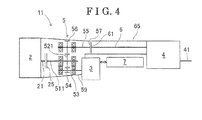
- Fig. 4 is a side view schematically explaining a drive unit for a hybrid vehicle according to a third embodiment disclosed here, in which a speed reduction device includes two input shafts.
- a drive unit 1 for a hybrid vehicle of the first embodiment includes an engine 2 and a generator-motor 3 (i.e., a motor) both of which are mounted on a front portion of a vehicle 9, a transmission 4 mounted on a rear portion of the vehicle 9, a speed reduction device 5 (i.e., an auxiliary transmission) connected to an output shaft 21 of the engine 2 and to an output shaft of the generator-motor 3, and a connecting shaft 6 connecting an output shaft 55 of the speed reduction device 5 to the transmission 4, and thus the drive unit 1 for the hybrid vehicle is structured to drive a driving rear wheel 91.
- a generator-motor 3 i.e., a motor
- a speed reduction device 5 i.e., an auxiliary transmission
- the engine 2 and the generator-motor 3 are coaxially arranged one behind the other, or in tandem. Because the transmission 4 is mounted on the rear portion of the vehicle 9, instead of the front portion thereof, a weight distribution of the vehicle 9 between the front/rear portions thereof, that is, the weight distribution in a front/rear direction, is well-balanced, and thus a high stability is assured.
- the drive unit 1 for the hybrid vehicle of the first embodiment is provided with a hybrid unit 7 which is configured by, for example, an electric power conversion device and a battery, and in which electric power is exchanged between the hybrid unit 7 and the generator-motor 3.
- the hybrid unit 7 may also include a drive control device.
- the same reference numerals as in the first embodiment designate portions which have identical functions and operations to those in the first embodiment.
- the output shaft 21 of the engine 2 is connected to an input shaft 51 of the speed reduction device 5 via a clutch 25.
- the output shaft of the generator-motor 3 is integrated with the input shaft 51 of the speed reduction device 5.
- the speed reduction device 5 corresponds to the auxiliary transmission, and is structured so that a drive gear 52 fixedly coupled to the input shaft 51 meshes at a predetermined speed reducing ratio with a driven gear 56 fixedly coupled to the output shaft 55 so as to transfer power.
- a connecting flange 57 is provided at a rear end portion of the output shaft 55 of the speed reduction device 5, and a connecting flange 61 is provided at a front end portion of the connecting shaft 6. The connecting flange 57 and the connecting flange 61 are connected to each other.
- the connecting shaft 6 is formed integrally with an input shaft of the transmission 4.
- a torque tube 65 accommodating and protecting the connecting shaft 6 is provided, and thus rigidity of the drive unit 1 is improved by the torque tube 65.
- An output shaft 41 of the transmission 4 is configured to transfer the power to the driving rear wheel 91 via a differential device.
- the generator-motor 3 is arranged to extend from a rear portion of the speed reduction device 5 in a front/rear direction of the vehicle 9 to a space below the torque tube 65. Part of the generator-motor 3 is incorporated in a case 59 of the speed reduction device 5. Further, the hybrid unit 7 is arranged below the torque tube 65 behind the generator-motor 3 in the front/rear direction of the vehicle 9.
- a dead space below the torque tube 65 is effectively used as mounting spaces for the generator-motor 3 and the hybrid unit 7, and thus the mounting spaces for the generator-motor 3 and the hybrid unit 7 are easily secured, thereby saving space.
- a conventional FR (front-engine/rear-drive) type vehicle is converted into a hybrid vehicle with slight labor and costs.
- the output shaft 21 of the engine 2 is configured to be disconnected from the input shaft 51 of the speed reduction device 5 by the clutch 25.
- the generator-motor 3 and the speed reduction device 5 are directly connected with each other, thereby generating no power loss, which allows a high transmitting efficiency.
- the second embodiment of this disclosure will be explained with reference to Fig. 3 , focusing on constructions that are different from the first embodiment.
- arrangement of the generator-motor 3 is different from that of the first embodiment.
- the generator-motor 3 is arranged to be closer to the rear portion of the speed reduction device 5 than to the front portion of the speed reduction device 5, and to be positioned at a lower portion of the speed reduction device 5 and to be forward relative to the torque tube 65, and a large part of the generator-motor 3 is incorporated in the case 59 of the speed reduction device 5.
- the generator-motor 3 is supported at the case 59 of the speed reduction device 5, there is no need to additionally provide a supporting member, and the arrangement of the generator-motor 3 is not restricted by the torque tube 65. Accordingly, the generator-motor 3 having a larger diameter may be mounted.
- the speed reduction device 5 includes two input shafts, that is, a first input shaft 511 and a second input shaft 53.
- the output shaft 21 of the engine 2 is connected to the first input shaft 511 via the clutch 25.
- the output shaft of the generator-motor 3 is integrated with the second input shaft 53 of the speed reducing device 5.
- the speed reduction device 5 is structured so that a first drive gear 521 fixedly coupled to the first input shaft 511 meshes at a predetermined engine-side speed reducing ratio with the driven gear 56 fixedly coupled to the output shaft 55 so as to transfer power. Further, a second drive gear 54 fixedly coupled to the second input shaft 53 meshes with the first drive gear 521 of the first input shaft 511. Accordingly, the generator-motor 3 is configured to drive the driven gear 56 and the output shaft 55 from the second drive gear 54 of the second input shaft 53 via the first drive gear 521.
- a motor-side speed reducing ratio may be defined independent from the engine-side speed reducing ratio by setting the number of teeth of the second drive gear 54 freely. Consequently, the motor-side speed reducing ratio which is optimally suited for motor-driven driving is set, and thus a high efficiency of the motor is obtained.
- the generator-motor 3 is arranged to be lower than the engine 2, that is, part of the generator-motor 3 is positioned lower than the engine 2, which lowers the center of gravity of the drive unit 11 and improves a vehicle stability.
- the generator-motor 3 is arranged away from the torque tube 65, which provides an effect that the generator-motor 3 having the larger diameter may be mounted.
- the generator-motor 3 is configured to drive the driven gear 56 from the second drive gear 54 via the first drive gear 521, however, the configuration of the generator-motor 3 is not limited thereto.
- the first input shaft 511 and the second input shaft 53 may be arranged in a manner that the generator-motor 3 drives the driven gear 56 directly from the second drive gear 54.
Landscapes
- Engineering & Computer Science (AREA)
- Chemical & Material Sciences (AREA)
- Combustion & Propulsion (AREA)
- Transportation (AREA)
- Mechanical Engineering (AREA)
- Hybrid Electric Vehicles (AREA)
- Arrangement Of Transmissions (AREA)
Abstract
Description
- This disclosure generally relates to a drive unit for a hybrid vehicle.
- A known hybrid vehicle, which is mounted with an engine and a generator-motor that serve as drive units, and in which an improvement of fuel efficiency, a high output and an environmental protection are realized by taking advantage of each of the engine and the generator-motor, is in practically in use. According to the aforementioned type of the hybrid vehicle, it is pointed out that a weight distribution of the vehicle between front/rear portions thereof is not well-balanced and thus an operational stability may be reduced in a case where the engine, the generator-motor and a transmission are mounted on a front portion or a rear portion of the vehicle in a concentrated manner. On the other hand, on some of FR (front-engine/rear-drive) type vehicles where the engine is mounted on the front portion of the vehicle and rear wheels are driven via a propeller shaft, a transmission is mounted on the rear portion of the vehicle. This is for a purpose of improving the operational stability during high speed driving of, for example, a sports car, in consideration of the weight distribution of the vehicle between the front/rear portions thereof.
- An example of a known drive unit is disclosed in
JP2006-290187A Patent reference 1, the aforementioned techniques are combined with each other so that the imbalance of the weight distribution between the front/rear portions of the vehicle is reduced even in case of the hybrid vehicle. According to the known drive unit for the hybrid vehicle disclosed in thePatent reference 1, an engine is mounted on one of a front portion and a rear portion of the vehicle, a transmission is mounted on the other one of the front portion and the rear portion of the vehicle, and a motor is arranged either closer to the engine or closer to the transmission. Accordingly, the weight distribution between the front/rear portions of the vehicle is not as imbalanced so as to be regarded as a problem, and thus a possibility of a reduction in the operational stability is eliminated. - According to the
Patent reference 1, the motor is arranged either closer to the engine or closer to the transmission, however, it is not easy to actually secure a mounting space. For example, in a case where the motor is additionally mounted on the conventional FR type vehicle where the transmission is mounted on the rear portion of the vehicle, there may be a need for a significant change in many peripheral parts and components in order to secure the mounting space, which tends to increase labor and/or costs. Further, an arrangement of the motor and/or a drive path to the transmission is restricted, and thus an efficiency of the motor and/or an efficiency of a power transmission may be reduced. - A need thus exists for a drive unit for a hybrid vehicle, in which a mounting space for a motor is easily secured, space-saving is realized, a conventional FR type vehicle is converted into a hybrid vehicle by adding slight labor and costs, and in addition a high efficiency of the motor and a high efficiency of a power transmission are assured.
- According to an aspect of this disclosure, a drive unit for a hybrid vehicle includes an engine mounted on a front portion of a vehicle, a motor mounted on the front portion of the vehicle, a transmission mounted on a rear portion of the vehicle, an auxiliary transmission connected to an output shaft of the engine and to an output shaft of the motor, and a connecting shaft connecting an output shaft of the auxiliary transmission to the transmission, wherein the motor is arranged to be closer to a rear portion of the auxiliary transmission than to a front portion of the auxiliary transmission in a front/rear direction of the vehicle and to be below the connecting shaft.
- According to the above described structure, the motor is arranged to be closer to the rear portion of the auxiliary transmission than to the front portion of the auxiliary transmission in the front/rear direction of the vehicle and to be below the connecting shaft. Thus, a dead space below the connecting shaft or below the torque tube accommodating therein the connecting shaft is used as a mounting space for the motor, and thus the mounting space for the motor is easily secured, thereby saving space. At the same time, by adding minor design changes to minimal peripheral parts and components, a conventional FR type vehicle is converted into a hybrid vehicle with slight labor and costs.
- According to another aspect of this disclosure, the engine and the motor are arranged coaxially in tandem, the output shaft of the engine is connected to an input shaft of the auxiliary transmission via a clutch, and the output shaft of the motor is integrated with the input shaft of the auxiliary transmission.
- According to the above described structure, the engine and the motor are arranged coaxially in tandem, the output shaft of the engine is connected to an input shaft of the auxiliary transmission via the clutch, and the output shaft of the motor is integrated with the input shaft of the auxiliary transmission. Consequently, the output shaft of the engine is configured to be disconnected from the input shaft of the auxiliary transmission by the clutch during motor-driven driving. Further, the motor and the auxiliary transmission are directly connected with each other, thereby generating no power loss, which brings a high transmitting efficiency.
- According to a further aspect of this disclosure, the auxiliary transmission includes a first input shaft and a second input shaft, the output shaft of the engine is connected to the first input shaft of the auxiliary transmission via the clutch, and the output shaft of the motor is integrated with the second input shaft of the auxiliary transmission.
- According to the above described structure, the auxiliary transmission includes the first input shaft and the second input shaft, the output shaft of the engine is connected to the first input shaft of the auxiliary transmission via the clutch, and the output shaft of the motor is integrated with the second input shaft of the auxiliary transmission. Consequently, a motor-side speed reducing ratio inside the auxiliary transmission may be set freely independent from an engine-side speed reducing ratio. Consequently, the motor-side speed reducing ratio which is optimally suited for the motor-driven driving is set, and thus the high efficiency of the motor is obtained.
- According to a further aspect of this disclosure, at least part of the motor is incorporated in a case constituting the auxiliary transmission.
- According to the above described structure, at least the part of the motor is incorporated in the case constituting the auxiliary transmission. Consequently, a member supporting the motor does not interfere with the case of the auxiliary transmission, and thus the motor having a larger diameter may be mounted.
- According to a further aspect of this disclosure, at least part of the motor is arranged below the torque tube accommodating the connecting shaft.
- According to a further aspect of this disclosure, the motor is a generator-motor being capable of for generating electric power, and at least one of an electric power conversion device, a battery and a drive control device is arranged behind the motor in the front/rear direction of the vehicle.
- According to the above described structure, at least one of the electric power conversion device, the battery and the drive control device is arranged behind the motor in the front/rear direction of the vehicle. Consequently, a dead space below the connecting shaft or below the torque tube accommodating therein the connecting shaft is used as mounting spaces for the motor, the battery or the drive control device, and thus the mounting spaces are easily secured, which saves space.
- The foregoing and additional features and characteristics of this disclosure will become more apparent from the following detailed description considered with the reference to the accompanying drawings, wherein:
-
Fig. 1 is a side view illustrating an entire vehicle mounted with a drive unit for a hybrid vehicle according to a first embodiment disclosed here; -
Fig. 2 is a side view schematically explaining the drive unit for the hybrid vehicle according to the first embodiment; -
Fig. 3 is a side view schematically explaining a drive unit for a hybrid vehicle according to a second embodiment disclosed here, in which an arrangement of a generator-motor is different from that of the first embodiment; and -
Fig. 4 is a side view schematically explaining a drive unit for a hybrid vehicle according to a third embodiment disclosed here, in which a speed reduction device includes two input shafts. - A first embodiment of this disclosure will be explained with reference to
Figs. 1 and 2 . As illustrated inFigs. 1 and/or 2, adrive unit 1 for a hybrid vehicle of the first embodiment includes anengine 2 and a generator-motor 3 (i.e., a motor) both of which are mounted on a front portion of avehicle 9, atransmission 4 mounted on a rear portion of thevehicle 9, a speed reduction device 5 (i.e., an auxiliary transmission) connected to anoutput shaft 21 of theengine 2 and to an output shaft of the generator-motor 3, and a connectingshaft 6 connecting anoutput shaft 55 of thespeed reduction device 5 to thetransmission 4, and thus thedrive unit 1 for the hybrid vehicle is structured to drive a drivingrear wheel 91. In the first embodiment, theengine 2 and the generator-motor 3 are coaxially arranged one behind the other, or in tandem. Because thetransmission 4 is mounted on the rear portion of thevehicle 9, instead of the front portion thereof, a weight distribution of thevehicle 9 between the front/rear portions thereof, that is, the weight distribution in a front/rear direction, is well-balanced, and thus a high stability is assured. - In
Fig. 2 , the left side and the right side correspond to the front portion and the rear portion of thevehicle 9, respectively. The up/down direction inFig. 2 corresponds to an up/down direction of thevehicle 9. In addition to the structure illustrated inFig. 1 , thedrive unit 1 for the hybrid vehicle of the first embodiment is provided with ahybrid unit 7 which is configured by, for example, an electric power conversion device and a battery, and in which electric power is exchanged between thehybrid unit 7 and the generator-motor 3. Thehybrid unit 7 may also include a drive control device. In second and third embodiments each of which will be described later, the same reference numerals as in the first embodiment designate portions which have identical functions and operations to those in the first embodiment. - The
output shaft 21 of theengine 2 is connected to aninput shaft 51 of thespeed reduction device 5 via aclutch 25. The output shaft of the generator-motor 3 is integrated with theinput shaft 51 of thespeed reduction device 5. Thespeed reduction device 5 corresponds to the auxiliary transmission, and is structured so that adrive gear 52 fixedly coupled to theinput shaft 51 meshes at a predetermined speed reducing ratio with a drivengear 56 fixedly coupled to theoutput shaft 55 so as to transfer power. A connectingflange 57 is provided at a rear end portion of theoutput shaft 55 of thespeed reduction device 5, and a connectingflange 61 is provided at a front end portion of the connectingshaft 6. The connectingflange 57 and the connectingflange 61 are connected to each other. The connectingshaft 6 is formed integrally with an input shaft of thetransmission 4. In addition, atorque tube 65 accommodating and protecting the connectingshaft 6 is provided, and thus rigidity of thedrive unit 1 is improved by thetorque tube 65. Anoutput shaft 41 of thetransmission 4 is configured to transfer the power to the drivingrear wheel 91 via a differential device. - As illustrated in
Fig. 2 , the generator-motor 3 is arranged to extend from a rear portion of thespeed reduction device 5 in a front/rear direction of thevehicle 9 to a space below thetorque tube 65. Part of the generator-motor 3 is incorporated in acase 59 of thespeed reduction device 5. Further, thehybrid unit 7 is arranged below thetorque tube 65 behind the generator-motor 3 in the front/rear direction of thevehicle 9. - According to the
drive unit 1 for the hybrid vehicle of the first embodiment, a dead space below thetorque tube 65 is effectively used as mounting spaces for the generator-motor 3 and thehybrid unit 7, and thus the mounting spaces for the generator-motor 3 and thehybrid unit 7 are easily secured, thereby saving space. At the same time, by adding minor design changes to minimal peripheral parts and components, a conventional FR (front-engine/rear-drive) type vehicle is converted into a hybrid vehicle with slight labor and costs. Further, theoutput shaft 21 of theengine 2 is configured to be disconnected from theinput shaft 51 of thespeed reduction device 5 by theclutch 25. Further, the generator-motor 3 and thespeed reduction device 5 are directly connected with each other, thereby generating no power loss, which allows a high transmitting efficiency. - Next, the second embodiment of this disclosure will be explained with reference to
Fig. 3 , focusing on constructions that are different from the first embodiment. In the second embodiment, arrangement of the generator-motor 3 is different from that of the first embodiment. As illustrated inFig. 3 , according to adrive unit 10 for a hybrid vehicle of the second embodiment, the generator-motor 3 is arranged to be closer to the rear portion of thespeed reduction device 5 than to the front portion of thespeed reduction device 5, and to be positioned at a lower portion of thespeed reduction device 5 and to be forward relative to thetorque tube 65, and a large part of the generator-motor 3 is incorporated in thecase 59 of thespeed reduction device 5. - According to the
drive unit 10 for the hybrid vehicle of the second embodiment, because the generator-motor 3 is supported at thecase 59 of thespeed reduction device 5, there is no need to additionally provide a supporting member, and the arrangement of the generator-motor 3 is not restricted by thetorque tube 65. Accordingly, the generator-motor 3 having a larger diameter may be mounted. - Next, the third embodiment of this disclosure will be explained with reference to
Fig. 4 , focusing on constructions that are different from the first and second embodiments. As illustrated inFig. 4 , according to adrive unit 11 for a hybrid vehicle of the third embodiment, thespeed reduction device 5 includes two input shafts, that is, afirst input shaft 511 and asecond input shaft 53. Theoutput shaft 21 of theengine 2 is connected to thefirst input shaft 511 via the clutch 25. The output shaft of the generator-motor 3 is integrated with thesecond input shaft 53 of thespeed reducing device 5. Thespeed reduction device 5 is structured so that afirst drive gear 521 fixedly coupled to thefirst input shaft 511 meshes at a predetermined engine-side speed reducing ratio with the drivengear 56 fixedly coupled to theoutput shaft 55 so as to transfer power. Further, asecond drive gear 54 fixedly coupled to thesecond input shaft 53 meshes with thefirst drive gear 521 of thefirst input shaft 511. Accordingly, the generator-motor 3 is configured to drive the drivengear 56 and theoutput shaft 55 from thesecond drive gear 54 of thesecond input shaft 53 via thefirst drive gear 521. - According to the
drive unit 11 for the hybrid vehicle of the third embodiment, a motor-side speed reducing ratio may be defined independent from the engine-side speed reducing ratio by setting the number of teeth of thesecond drive gear 54 freely. Consequently, the motor-side speed reducing ratio which is optimally suited for motor-driven driving is set, and thus a high efficiency of the motor is obtained. In addition, because thesecond input shaft 53 is arranged below thefirst input shaft 511 as illustrated inFig. 4 , the generator-motor 3 is arranged to be lower than theengine 2, that is, part of the generator-motor 3 is positioned lower than theengine 2, which lowers the center of gravity of thedrive unit 11 and improves a vehicle stability. In addition, the generator-motor 3 is arranged away from thetorque tube 65, which provides an effect that the generator-motor 3 having the larger diameter may be mounted. - In the third embodiment, the generator-
motor 3 is configured to drive the drivengear 56 from thesecond drive gear 54 via thefirst drive gear 521, however, the configuration of the generator-motor 3 is not limited thereto. Specifically, thefirst input shaft 511 and thesecond input shaft 53 may be arranged in a manner that the generator-motor 3 drives the drivengear 56 directly from thesecond drive gear 54.
Claims (6)
- A drive unit (1, 10, 11) for a hybrid vehicle, comprising:an engine (2) mounted on a front portion of a vehicle (9);a motor (3) mounted on the front portion of the vehicle (9);a transmission (4) mounted on a rear portion of the vehicle (9);an auxiliary transmission (5) connected to an output shaft (21) of the engine (2) and to an output shaft of the motor (3); anda connecting shaft (6) connecting an output shaft (55) of the auxiliary transmission (5) to the transmission (4), whereinthe motor (3) is arranged to be closer to a rear portion of the auxiliary transmission (5) than to a front portion of the auxiliary transmission (5) in a front/rear direction of the vehicle (9) and to be below the connecting shaft (6).
- The drive unit (1, 10) for the hybrid vehicle according to claim 1, wherein
the engine (2) and the motor (3) are arranged coaxially in tandem,
the output shaft (21) of the engine (2) is connected to an input shaft (51) of the auxiliary transmission (5) via a clutch (25), and
the output shaft of the motor (3) is integrated with the input shaft (51) of the auxiliary transmission (5). - The drive unit (11) for the hybrid vehicle according to claim 1, wherein
the auxiliary transmission (5) includes a first input shaft (511) and a second input shaft (53),
the output shaft (21) of the engine (2) is connected to the first input shaft (511) of the auxiliary transmission (5) via the clutch (25), and
the output shaft of the motor (3) is integrated with the second input shaft (53) of the auxiliary transmission (5). - The drive unit (1, 10, 11) for the hybrid vehicle according to any one of claims 1 through 3, wherein at least part of the motor (3) is incorporated in a case (59) constituting the auxiliary transmission (5).
- The drive unit (1, 11) for the hybrid vehicle according to any one of claims 1 through 4, wherein at least part of the motor (3) is arranged below a torque tube (65) accommodating the connecting shaft (6).
- The drive unit (1, 10, 11) for the hybrid vehicle according to any one of claims 1 through 5, wherein the motor (3) is a generator-motor (3) being capable of generating electric power, and at least one of an electric power conversion device, a battery and a drive control device is arranged behind the generator-motor (3) in the front/rear direction of the vehicle (9).
Applications Claiming Priority (1)
| Application Number | Priority Date | Filing Date | Title |
|---|---|---|---|
| JP2011136624A JP5879054B2 (en) | 2011-06-20 | 2011-06-20 | Hybrid vehicle drive system |
Publications (2)
| Publication Number | Publication Date |
|---|---|
| EP2537695A1 true EP2537695A1 (en) | 2012-12-26 |
| EP2537695B1 EP2537695B1 (en) | 2016-04-13 |
Family
ID=46331049
Family Applications (1)
| Application Number | Title | Priority Date | Filing Date |
|---|---|---|---|
| EP12172675.6A Not-in-force EP2537695B1 (en) | 2011-06-20 | 2012-06-20 | Drive unit for hybrid vehicle |
Country Status (3)
| Country | Link |
|---|---|
| US (1) | US8534162B2 (en) |
| EP (1) | EP2537695B1 (en) |
| JP (1) | JP5879054B2 (en) |
Families Citing this family (6)
| Publication number | Priority date | Publication date | Assignee | Title |
|---|---|---|---|---|
| DE102012100865B4 (en) * | 2012-02-02 | 2016-10-27 | Gkn Driveline International Gmbh | Drive arrangement with electric machine and motor vehicle with such a drive arrangement |
| JP2014111409A (en) * | 2012-12-05 | 2014-06-19 | Toyota Motor Corp | Transfer |
| JP7217860B2 (en) * | 2018-03-20 | 2023-02-06 | マツダ株式会社 | vehicle drive |
| CN108422849A (en) * | 2018-04-04 | 2018-08-21 | 精进电动科技股份有限公司 | A kind of longitudinal dual power source vehicle traction assembly |
| JP7144738B2 (en) * | 2018-10-19 | 2022-09-30 | マツダ株式会社 | vehicle drive |
| JP7118363B2 (en) * | 2018-12-05 | 2022-08-16 | マツダ株式会社 | vehicle drive |
Citations (6)
| Publication number | Priority date | Publication date | Assignee | Title |
|---|---|---|---|---|
| EP0444467A1 (en) * | 1990-02-19 | 1991-09-04 | F.Lli Macchi S.P.A. | A city refuse collector vehicle |
| EP0510582A2 (en) * | 1991-04-23 | 1992-10-28 | IVECO FIAT S.p.A. | Vehicle powerplant featuring thermal and electrical drive means |
| EP1203683A2 (en) * | 2000-11-03 | 2002-05-08 | Shenzhen Minghua Environmental Protection Vehicle Co., Ltd. | Hybrid electric environmental protection automobile |
| US20060111216A1 (en) * | 2004-11-24 | 2006-05-25 | Toyota Jidosha Kabushiki Kaisha | Torque tube apparatus |
| JP2006290187A (en) | 2005-04-12 | 2006-10-26 | Nissan Motor Co Ltd | Hybrid drive device for vehicle |
| FR2912696A1 (en) * | 2007-02-21 | 2008-08-22 | Renault Sas | Power distribution transmission for motor vehicle, has electric machines arranged on axis, and mode changing device and two of three planetary gear trains reassembled in principal axial zone of transmission |
Family Cites Families (8)
| Publication number | Priority date | Publication date | Assignee | Title |
|---|---|---|---|---|
| US3108660A (en) * | 1961-09-11 | 1963-10-29 | Ray F Smith | Hydrodynamic brake |
| US3260130A (en) * | 1963-07-29 | 1966-07-12 | Charlie C Pitts | Ventilation system for gear housings |
| US3442153A (en) * | 1967-05-08 | 1969-05-06 | Sundstrand Corp | Hydrostatic transmission |
| JP2563629B2 (en) * | 1990-02-14 | 1996-12-11 | 日産自動車株式会社 | Powertrain for four-wheel drive vehicles |
| JPH06211061A (en) * | 1992-11-13 | 1994-08-02 | Komatsu Ltd | Work vehicle |
| JP3350314B2 (en) * | 1995-09-29 | 2002-11-25 | 富士重工業株式会社 | Hybrid vehicle drive system |
| JP3940260B2 (en) * | 2000-10-16 | 2007-07-04 | 日産ディーゼル工業株式会社 | Vehicle hybrid system |
| JP2008174118A (en) * | 2007-01-19 | 2008-07-31 | Nissan Diesel Motor Co Ltd | Power train for hybrid vehicle |
-
2011
- 2011-06-20 JP JP2011136624A patent/JP5879054B2/en not_active Expired - Fee Related
-
2012
- 2012-06-15 US US13/524,278 patent/US8534162B2/en not_active Expired - Fee Related
- 2012-06-20 EP EP12172675.6A patent/EP2537695B1/en not_active Not-in-force
Patent Citations (6)
| Publication number | Priority date | Publication date | Assignee | Title |
|---|---|---|---|---|
| EP0444467A1 (en) * | 1990-02-19 | 1991-09-04 | F.Lli Macchi S.P.A. | A city refuse collector vehicle |
| EP0510582A2 (en) * | 1991-04-23 | 1992-10-28 | IVECO FIAT S.p.A. | Vehicle powerplant featuring thermal and electrical drive means |
| EP1203683A2 (en) * | 2000-11-03 | 2002-05-08 | Shenzhen Minghua Environmental Protection Vehicle Co., Ltd. | Hybrid electric environmental protection automobile |
| US20060111216A1 (en) * | 2004-11-24 | 2006-05-25 | Toyota Jidosha Kabushiki Kaisha | Torque tube apparatus |
| JP2006290187A (en) | 2005-04-12 | 2006-10-26 | Nissan Motor Co Ltd | Hybrid drive device for vehicle |
| FR2912696A1 (en) * | 2007-02-21 | 2008-08-22 | Renault Sas | Power distribution transmission for motor vehicle, has electric machines arranged on axis, and mode changing device and two of three planetary gear trains reassembled in principal axial zone of transmission |
Also Published As
| Publication number | Publication date |
|---|---|
| US8534162B2 (en) | 2013-09-17 |
| US20120318099A1 (en) | 2012-12-20 |
| JP5879054B2 (en) | 2016-03-08 |
| EP2537695B1 (en) | 2016-04-13 |
| JP2013001330A (en) | 2013-01-07 |
Similar Documents
| Publication | Publication Date | Title |
|---|---|---|
| EP3644479B1 (en) | High torque and power density drive system with shortened overall width | |
| EP2537695B1 (en) | Drive unit for hybrid vehicle | |
| KR101755069B1 (en) | Hybrid work vehicle | |
| JP2013121788A (en) | Driving device for vehicle | |
| JP2013121823A (en) | Power transmission device of vehicle | |
| CN209813696U (en) | Vehicle and electric drive power assembly thereof | |
| KR20120112815A (en) | Drive train of a motor vehicle | |
| CN202080105U (en) | Driving equipment for electric vehicle | |
| WO2010095610A1 (en) | Hybrid electric vehicle | |
| EP2340953B1 (en) | An improved in-wheel motor structure | |
| CN210821808U (en) | Dual-motor series-parallel hybrid power system and vehicle with same | |
| WO2018079615A1 (en) | Vehicle | |
| JP5903277B2 (en) | Vehicle drive device | |
| CN102310754B (en) | Transmission system and chassis | |
| CN101277043B (en) | Frequency control motor and generating set for hybrid vehicle | |
| EP2158101A1 (en) | Device for a motor vehicle and a vehicle provide with such device | |
| CN204340634U (en) | A kind of automobile dynamic system arrangement structure | |
| KR101639235B1 (en) | Hybrid electric vehicle | |
| WO2018079712A1 (en) | Vehicle | |
| CN102795093B (en) | Hybrid power transmission device and hybrid power automobile | |
| JP2018043676A (en) | Work vehicle | |
| CN211820615U (en) | Auxiliary motor rear-mounted hybrid transmission | |
| JP2010159024A (en) | Power transmission | |
| CN219904044U (en) | Dual-motor hybrid system | |
| KR101475873B1 (en) | Electric power device for vehicle |
Legal Events
| Date | Code | Title | Description |
|---|---|---|---|
| PUAI | Public reference made under article 153(3) epc to a published international application that has entered the european phase |
Free format text: ORIGINAL CODE: 0009012 |
|
| 17P | Request for examination filed |
Effective date: 20120620 |
|
| AK | Designated contracting states |
Kind code of ref document: A1 Designated state(s): AL AT BE BG CH CY CZ DE DK EE ES FI FR GB GR HR HU IE IS IT LI LT LU LV MC MK MT NL NO PL PT RO RS SE SI SK SM TR |
|
| AX | Request for extension of the european patent |
Extension state: BA ME |
|
| 17Q | First examination report despatched |
Effective date: 20150409 |
|
| GRAP | Despatch of communication of intention to grant a patent |
Free format text: ORIGINAL CODE: EPIDOSNIGR1 |
|
| INTG | Intention to grant announced |
Effective date: 20150925 |
|
| GRAS | Grant fee paid |
Free format text: ORIGINAL CODE: EPIDOSNIGR3 |
|
| GRAA | (expected) grant |
Free format text: ORIGINAL CODE: 0009210 |
|
| RAP1 | Party data changed (applicant data changed or rights of an application transferred) |
Owner name: AISIN SEIKI KABUSHIKI KAISHA Owner name: AISIN AI CO., LTD. |
|
| RIN1 | Information on inventor provided before grant (corrected) |
Inventor name: SASAKI, KAN Inventor name: KOIDE, TAKEHARU Inventor name: HAYASHI, YOSUKE Inventor name: OKAWA, AKEMI C/O INTELLECTUAL PROPERTY DEPARTMENT, |
|
| AK | Designated contracting states |
Kind code of ref document: B1 Designated state(s): AL AT BE BG CH CY CZ DE DK EE ES FI FR GB GR HR HU IE IS IT LI LT LU LV MC MK MT NL NO PL PT RO RS SE SI SK SM TR |
|
| REG | Reference to a national code |
Ref country code: GB Ref legal event code: FG4D |
|
| REG | Reference to a national code |
Ref country code: AT Ref legal event code: REF Ref document number: 789716 Country of ref document: AT Kind code of ref document: T Effective date: 20160415 Ref country code: CH Ref legal event code: EP |
|
| REG | Reference to a national code |
Ref country code: IE Ref legal event code: FG4D |
|
| REG | Reference to a national code |
Ref country code: DE Ref legal event code: R096 Ref document number: 602012016970 Country of ref document: DE |
|
| REG | Reference to a national code |
Ref country code: FR Ref legal event code: PLFP Year of fee payment: 5 |
|
| REG | Reference to a national code |
Ref country code: LT Ref legal event code: MG4D |
|
| REG | Reference to a national code |
Ref country code: AT Ref legal event code: MK05 Ref document number: 789716 Country of ref document: AT Kind code of ref document: T Effective date: 20160413 |
|
| REG | Reference to a national code |
Ref country code: NL Ref legal event code: MP Effective date: 20160413 |
|
| PG25 | Lapsed in a contracting state [announced via postgrant information from national office to epo] |
Ref country code: NL Free format text: LAPSE BECAUSE OF FAILURE TO SUBMIT A TRANSLATION OF THE DESCRIPTION OR TO PAY THE FEE WITHIN THE PRESCRIBED TIME-LIMIT Effective date: 20160413 Ref country code: NO Free format text: LAPSE BECAUSE OF FAILURE TO SUBMIT A TRANSLATION OF THE DESCRIPTION OR TO PAY THE FEE WITHIN THE PRESCRIBED TIME-LIMIT Effective date: 20160713 Ref country code: LT Free format text: LAPSE BECAUSE OF FAILURE TO SUBMIT A TRANSLATION OF THE DESCRIPTION OR TO PAY THE FEE WITHIN THE PRESCRIBED TIME-LIMIT Effective date: 20160413 Ref country code: PL Free format text: LAPSE BECAUSE OF FAILURE TO SUBMIT A TRANSLATION OF THE DESCRIPTION OR TO PAY THE FEE WITHIN THE PRESCRIBED TIME-LIMIT Effective date: 20160413 Ref country code: FI Free format text: LAPSE BECAUSE OF FAILURE TO SUBMIT A TRANSLATION OF THE DESCRIPTION OR TO PAY THE FEE WITHIN THE PRESCRIBED TIME-LIMIT Effective date: 20160413 |
|
| PG25 | Lapsed in a contracting state [announced via postgrant information from national office to epo] |
Ref country code: ES Free format text: LAPSE BECAUSE OF FAILURE TO SUBMIT A TRANSLATION OF THE DESCRIPTION OR TO PAY THE FEE WITHIN THE PRESCRIBED TIME-LIMIT Effective date: 20160413 Ref country code: AT Free format text: LAPSE BECAUSE OF FAILURE TO SUBMIT A TRANSLATION OF THE DESCRIPTION OR TO PAY THE FEE WITHIN THE PRESCRIBED TIME-LIMIT Effective date: 20160413 Ref country code: SE Free format text: LAPSE BECAUSE OF FAILURE TO SUBMIT A TRANSLATION OF THE DESCRIPTION OR TO PAY THE FEE WITHIN THE PRESCRIBED TIME-LIMIT Effective date: 20160413 Ref country code: RS Free format text: LAPSE BECAUSE OF FAILURE TO SUBMIT A TRANSLATION OF THE DESCRIPTION OR TO PAY THE FEE WITHIN THE PRESCRIBED TIME-LIMIT Effective date: 20160413 Ref country code: GR Free format text: LAPSE BECAUSE OF FAILURE TO SUBMIT A TRANSLATION OF THE DESCRIPTION OR TO PAY THE FEE WITHIN THE PRESCRIBED TIME-LIMIT Effective date: 20160714 Ref country code: PT Free format text: LAPSE BECAUSE OF FAILURE TO SUBMIT A TRANSLATION OF THE DESCRIPTION OR TO PAY THE FEE WITHIN THE PRESCRIBED TIME-LIMIT Effective date: 20160816 Ref country code: HR Free format text: LAPSE BECAUSE OF FAILURE TO SUBMIT A TRANSLATION OF THE DESCRIPTION OR TO PAY THE FEE WITHIN THE PRESCRIBED TIME-LIMIT Effective date: 20160413 Ref country code: LV Free format text: LAPSE BECAUSE OF FAILURE TO SUBMIT A TRANSLATION OF THE DESCRIPTION OR TO PAY THE FEE WITHIN THE PRESCRIBED TIME-LIMIT Effective date: 20160413 |
|
| PG25 | Lapsed in a contracting state [announced via postgrant information from national office to epo] |
Ref country code: IT Free format text: LAPSE BECAUSE OF FAILURE TO SUBMIT A TRANSLATION OF THE DESCRIPTION OR TO PAY THE FEE WITHIN THE PRESCRIBED TIME-LIMIT Effective date: 20160413 Ref country code: BE Free format text: LAPSE BECAUSE OF FAILURE TO SUBMIT A TRANSLATION OF THE DESCRIPTION OR TO PAY THE FEE WITHIN THE PRESCRIBED TIME-LIMIT Effective date: 20160413 |
|
| REG | Reference to a national code |
Ref country code: DE Ref legal event code: R097 Ref document number: 602012016970 Country of ref document: DE |
|
| PG25 | Lapsed in a contracting state [announced via postgrant information from national office to epo] |
Ref country code: EE Free format text: LAPSE BECAUSE OF FAILURE TO SUBMIT A TRANSLATION OF THE DESCRIPTION OR TO PAY THE FEE WITHIN THE PRESCRIBED TIME-LIMIT Effective date: 20160413 Ref country code: RO Free format text: LAPSE BECAUSE OF FAILURE TO SUBMIT A TRANSLATION OF THE DESCRIPTION OR TO PAY THE FEE WITHIN THE PRESCRIBED TIME-LIMIT Effective date: 20160413 Ref country code: DK Free format text: LAPSE BECAUSE OF FAILURE TO SUBMIT A TRANSLATION OF THE DESCRIPTION OR TO PAY THE FEE WITHIN THE PRESCRIBED TIME-LIMIT Effective date: 20160413 Ref country code: CZ Free format text: LAPSE BECAUSE OF FAILURE TO SUBMIT A TRANSLATION OF THE DESCRIPTION OR TO PAY THE FEE WITHIN THE PRESCRIBED TIME-LIMIT Effective date: 20160413 Ref country code: MC Free format text: LAPSE BECAUSE OF FAILURE TO SUBMIT A TRANSLATION OF THE DESCRIPTION OR TO PAY THE FEE WITHIN THE PRESCRIBED TIME-LIMIT Effective date: 20160413 Ref country code: SK Free format text: LAPSE BECAUSE OF FAILURE TO SUBMIT A TRANSLATION OF THE DESCRIPTION OR TO PAY THE FEE WITHIN THE PRESCRIBED TIME-LIMIT Effective date: 20160413 |
|
| REG | Reference to a national code |
Ref country code: CH Ref legal event code: PL |
|
| PLBE | No opposition filed within time limit |
Free format text: ORIGINAL CODE: 0009261 |
|
| STAA | Information on the status of an ep patent application or granted ep patent |
Free format text: STATUS: NO OPPOSITION FILED WITHIN TIME LIMIT |
|
| PG25 | Lapsed in a contracting state [announced via postgrant information from national office to epo] |
Ref country code: SM Free format text: LAPSE BECAUSE OF FAILURE TO SUBMIT A TRANSLATION OF THE DESCRIPTION OR TO PAY THE FEE WITHIN THE PRESCRIBED TIME-LIMIT Effective date: 20160413 |
|
| 26N | No opposition filed |
Effective date: 20170116 |
|
| GBPC | Gb: european patent ceased through non-payment of renewal fee |
Effective date: 20160713 |
|
| REG | Reference to a national code |
Ref country code: IE Ref legal event code: MM4A |
|
| PG25 | Lapsed in a contracting state [announced via postgrant information from national office to epo] |
Ref country code: CH Free format text: LAPSE BECAUSE OF NON-PAYMENT OF DUE FEES Effective date: 20160630 Ref country code: LI Free format text: LAPSE BECAUSE OF NON-PAYMENT OF DUE FEES Effective date: 20160630 |
|
| REG | Reference to a national code |
Ref country code: FR Ref legal event code: PLFP Year of fee payment: 6 |
|
| PG25 | Lapsed in a contracting state [announced via postgrant information from national office to epo] |
Ref country code: SI Free format text: LAPSE BECAUSE OF FAILURE TO SUBMIT A TRANSLATION OF THE DESCRIPTION OR TO PAY THE FEE WITHIN THE PRESCRIBED TIME-LIMIT Effective date: 20160413 Ref country code: GB Free format text: LAPSE BECAUSE OF NON-PAYMENT OF DUE FEES Effective date: 20160713 Ref country code: IE Free format text: LAPSE BECAUSE OF NON-PAYMENT OF DUE FEES Effective date: 20160620 |
|
| REG | Reference to a national code |
Ref country code: FR Ref legal event code: PLFP Year of fee payment: 7 |
|
| PG25 | Lapsed in a contracting state [announced via postgrant information from national office to epo] |
Ref country code: CY Free format text: LAPSE BECAUSE OF FAILURE TO SUBMIT A TRANSLATION OF THE DESCRIPTION OR TO PAY THE FEE WITHIN THE PRESCRIBED TIME-LIMIT Effective date: 20160413 Ref country code: HU Free format text: LAPSE BECAUSE OF FAILURE TO SUBMIT A TRANSLATION OF THE DESCRIPTION OR TO PAY THE FEE WITHIN THE PRESCRIBED TIME-LIMIT; INVALID AB INITIO Effective date: 20120620 |
|
| PG25 | Lapsed in a contracting state [announced via postgrant information from national office to epo] |
Ref country code: LU Free format text: LAPSE BECAUSE OF NON-PAYMENT OF DUE FEES Effective date: 20160620 Ref country code: IS Free format text: LAPSE BECAUSE OF FAILURE TO SUBMIT A TRANSLATION OF THE DESCRIPTION OR TO PAY THE FEE WITHIN THE PRESCRIBED TIME-LIMIT Effective date: 20160413 Ref country code: MT Free format text: LAPSE BECAUSE OF NON-PAYMENT OF DUE FEES Effective date: 20160630 Ref country code: MK Free format text: LAPSE BECAUSE OF FAILURE TO SUBMIT A TRANSLATION OF THE DESCRIPTION OR TO PAY THE FEE WITHIN THE PRESCRIBED TIME-LIMIT Effective date: 20160413 Ref country code: TR Free format text: LAPSE BECAUSE OF FAILURE TO SUBMIT A TRANSLATION OF THE DESCRIPTION OR TO PAY THE FEE WITHIN THE PRESCRIBED TIME-LIMIT Effective date: 20160413 |
|
| PG25 | Lapsed in a contracting state [announced via postgrant information from national office to epo] |
Ref country code: BG Free format text: LAPSE BECAUSE OF FAILURE TO SUBMIT A TRANSLATION OF THE DESCRIPTION OR TO PAY THE FEE WITHIN THE PRESCRIBED TIME-LIMIT Effective date: 20160413 |
|
| PG25 | Lapsed in a contracting state [announced via postgrant information from national office to epo] |
Ref country code: AL Free format text: LAPSE BECAUSE OF FAILURE TO SUBMIT A TRANSLATION OF THE DESCRIPTION OR TO PAY THE FEE WITHIN THE PRESCRIBED TIME-LIMIT Effective date: 20160413 |
|
| RIC2 | Information provided on ipc code assigned after grant |
Ipc: B60K 17/22 20060101ALI20120927BHEP Ipc: B60K 17/08 20060101ALI20120927BHEP Ipc: B60K 6/48 20071001AFI20120927BHEP Ipc: B60K 6/40 20071001ALI20120927BHEP |
|
| PGFP | Annual fee paid to national office [announced via postgrant information from national office to epo] |
Ref country code: DE Payment date: 20190604 Year of fee payment: 8 |
|
| PGFP | Annual fee paid to national office [announced via postgrant information from national office to epo] |
Ref country code: FR Payment date: 20190510 Year of fee payment: 8 |
|
| REG | Reference to a national code |
Ref country code: DE Ref legal event code: R119 Ref document number: 602012016970 Country of ref document: DE |
|
| PG25 | Lapsed in a contracting state [announced via postgrant information from national office to epo] |
Ref country code: FR Free format text: LAPSE BECAUSE OF NON-PAYMENT OF DUE FEES Effective date: 20200630 |
|
| PG25 | Lapsed in a contracting state [announced via postgrant information from national office to epo] |
Ref country code: DE Free format text: LAPSE BECAUSE OF NON-PAYMENT OF DUE FEES Effective date: 20210101 |