EP2537460B1 - Method and system for ischemia detection - Google Patents
Method and system for ischemia detection Download PDFInfo
- Publication number
- EP2537460B1 EP2537460B1 EP11170536.4A EP11170536A EP2537460B1 EP 2537460 B1 EP2537460 B1 EP 2537460B1 EP 11170536 A EP11170536 A EP 11170536A EP 2537460 B1 EP2537460 B1 EP 2537460B1
- Authority
- EP
- European Patent Office
- Prior art keywords
- window
- threshold
- wave
- value
- cardiac
- Prior art date
- Legal status (The legal status is an assumption and is not a legal conclusion. Google has not performed a legal analysis and makes no representation as to the accuracy of the status listed.)
- Not-in-force
Links
Images

Classifications
-
- A—HUMAN NECESSITIES
- A61—MEDICAL OR VETERINARY SCIENCE; HYGIENE
- A61B—DIAGNOSIS; SURGERY; IDENTIFICATION
- A61B5/00—Measuring for diagnostic purposes; Identification of persons
- A61B5/24—Detecting, measuring or recording bioelectric or biomagnetic signals of the body or parts thereof
- A61B5/316—Modalities, i.e. specific diagnostic methods
- A61B5/318—Heart-related electrical modalities, e.g. electrocardiography [ECG]
- A61B5/346—Analysis of electrocardiograms
- A61B5/349—Detecting specific parameters of the electrocardiograph cycle
- A61B5/366—Detecting abnormal QRS complex, e.g. widening
-
- A—HUMAN NECESSITIES
- A61—MEDICAL OR VETERINARY SCIENCE; HYGIENE
- A61B—DIAGNOSIS; SURGERY; IDENTIFICATION
- A61B5/00—Measuring for diagnostic purposes; Identification of persons
- A61B5/145—Measuring characteristics of blood in vivo, e.g. gas concentration, pH value; Measuring characteristics of body fluids or tissues, e.g. interstitial fluid, cerebral tissue
- A61B5/14542—Measuring characteristics of blood in vivo, e.g. gas concentration, pH value; Measuring characteristics of body fluids or tissues, e.g. interstitial fluid, cerebral tissue for measuring blood gases
-
- A—HUMAN NECESSITIES
- A61—MEDICAL OR VETERINARY SCIENCE; HYGIENE
- A61B—DIAGNOSIS; SURGERY; IDENTIFICATION
- A61B5/00—Measuring for diagnostic purposes; Identification of persons
- A61B5/24—Detecting, measuring or recording bioelectric or biomagnetic signals of the body or parts thereof
- A61B5/316—Modalities, i.e. specific diagnostic methods
- A61B5/318—Heart-related electrical modalities, e.g. electrocardiography [ECG]
- A61B5/346—Analysis of electrocardiograms
- A61B5/349—Detecting specific parameters of the electrocardiograph cycle
- A61B5/352—Detecting R peaks, e.g. for synchronising diagnostic apparatus; Estimating R-R interval
-
- A—HUMAN NECESSITIES
- A61—MEDICAL OR VETERINARY SCIENCE; HYGIENE
- A61B—DIAGNOSIS; SURGERY; IDENTIFICATION
- A61B5/00—Measuring for diagnostic purposes; Identification of persons
- A61B5/72—Signal processing specially adapted for physiological signals or for diagnostic purposes
- A61B5/7235—Details of waveform analysis
- A61B5/7239—Details of waveform analysis using differentiation including higher order derivatives
-
- A—HUMAN NECESSITIES
- A61—MEDICAL OR VETERINARY SCIENCE; HYGIENE
- A61N—ELECTROTHERAPY; MAGNETOTHERAPY; RADIATION THERAPY; ULTRASOUND THERAPY
- A61N1/00—Electrotherapy; Circuits therefor
- A61N1/18—Applying electric currents by contact electrodes
- A61N1/32—Applying electric currents by contact electrodes alternating or intermittent currents
- A61N1/36—Applying electric currents by contact electrodes alternating or intermittent currents for stimulation
- A61N1/362—Heart stimulators
- A61N1/365—Heart stimulators controlled by a physiological parameter, e.g. heart potential
- A61N1/36514—Heart stimulators controlled by a physiological parameter, e.g. heart potential controlled by a physiological quantity other than heart potential, e.g. blood pressure
- A61N1/36557—Heart stimulators controlled by a physiological parameter, e.g. heart potential controlled by a physiological quantity other than heart potential, e.g. blood pressure controlled by chemical substances in blood
-
- A—HUMAN NECESSITIES
- A61—MEDICAL OR VETERINARY SCIENCE; HYGIENE
- A61N—ELECTROTHERAPY; MAGNETOTHERAPY; RADIATION THERAPY; ULTRASOUND THERAPY
- A61N1/00—Electrotherapy; Circuits therefor
- A61N1/18—Applying electric currents by contact electrodes
- A61N1/32—Applying electric currents by contact electrodes alternating or intermittent currents
- A61N1/36—Applying electric currents by contact electrodes alternating or intermittent currents for stimulation
- A61N1/362—Heart stimulators
- A61N1/37—Monitoring; Protecting
- A61N1/3702—Physiological parameters
Definitions
- the present invention relates generally to implantable medical devices and more particularly to systems and methods for automatically determining ST windows for ischemia detection.
- Electrocardiograms are useful for diagnosing ischemia and locate damaged areas within the heart. Cardiac ischemia is a condition whereby heart tissue does not receive adequate amounts of oxygen and is usually caused by a blockage of an artery leading to damage of heart tissue. ECGs are composed of various waves and segments that represent the heart depolarization and repolarization. The ST segment represent the portion of the cardiac signal between ventricular depolarization and ventricular repolarization.
- the ST window is a fixed time interval relative the R-wave. This may lead to that the ST window may encompass parts of the T-wave or the R-wave. If changes occur to the amplitude of the T-wave or R-wave, this may result in a false indication of an ST episode. Accordingly, there is a need of improving the specificity of these prior art methods. Such improvement can be achieved by allowing manual adjustments of the default parameters defining e.g. the fixed time interval to adapt the parameters to a specific patient.
- An ischemia detection window is based on physiological state indicators that define start and end of the ischemia detection window.
- the physiological state indicators can be located by identifying slope changes after the R-wave and before the T-wave, respectively. Slope changes are recognized by identifying when the derivative of the composite intrinsic baseline changes sign from positive to negative or vice versa following the R-wave marker. The slope changes are used to locate ischemia detection parameters (e.g. start and end of ST window).
- a first ischemia detection parameter (indicating the start of the ST window) can be identified as a point along the baseline following the first slope change but with a predetermined offset (e.g. about 25 msec).
- a second ischemia detection parameter (indicating the end of the ST window) can be identified as a point along the baseline preceding the third slope change with a negative offset (e.g. about 35 msec).
- US 2011/0040200 A1 discloses a system for analyzing an ECG signal.
- One out of two isoelectric portions in the ECG signal is adaptively selected for a heart beat cycle as a baseline based on stability measures.
- a point of reference of an ST segments in the heart beat cycle is determined.
- a deviation of the point of reference on the ST segment from the selected baseline is evaluated.
- US 2008/0058881 A1 discloses an implantable device for delivering phototherapy for treatment of post-MI patients.
- US 2007/0150015 A1 discloses a cardiac device with the capability of detecting cardiac ischemia using multiple sensing modalities.
- An object of the present invention is to provide systems for improving the specificity of the ischemia detection.
- Another object of the present invention is to provide systems for automatically determining ST windows for use in ischemia detection.
- a method for ischemia detection not forming part of the current invention, comprising obtaining at least one IEGM signal representative of cardiac behavior of a patient over a period of time and calculating a derivative signal of the IEGM signal.
- the R-wave is identified in the derivative signal or in the original IEGM signal and data of the derivative signal following the identified R-wave is analyzed so as to find portions of the derivative signal comprising samples having lower values than a predetermined threshold. Further, a portion of the derivative signal including samples having lower values than the threshold is determined to correspond to a ST window for that cardiac cycle if that portion fulfills predetermined requirements.
- a reference ST window based on a number of determined ST windows is determined.
- ischemia can be detected by comparing IEGM data in the reference ST window with current IEGM data from a segment of the IEGM signal corresponding to the reference ST window.
- a shift in the ST segment i.e. the portion of the signal in the ST window, from a baseline or reference level is an indication of cardiac ischemia.
- a depression of the IEGM signal in the ST window may be an indication of cardiac ischemia.
- Deviation of the ST segment from a baseline may be a result of an injury to cardiac muscle arising from differences in electric potential between cells that have become ischemic and those cells still receiving normal blood flow.
- a system for ischemia detection comprising a data collection module configured to obtain at least one IEGM signal indicating cardiac behavior of a cardiac cycle corresponding a heartbeat and a data processing module configured to calculate a derivative signal of the IEGM signal. Furthermore, the system comprises a morphology detector configured to identify an R-wave in the derivative signal or in the original IEGM signal and an ST window determining module.
- the ST window determining module is configured to analyze the derivative signal data following the identified R-wave so as to find portions of the derivative signal comprising samples having lower values than a predetermined threshold, determine a portion of the derivative signal including samples having lower values than the threshold to correspond to a ST window for that cardiac cycle if that portion fulfills predetermined requirements and create a reference ST window based on a number of determined ST windows.
- An ischemia detection module is configured to detect ischemia by comparing IEGM data in the reference ST window with current IEGM data from a segment of the IEGM signal corresponding to the reference ST window.
- all or some modules of the system are implemented in an implantable medical device or cardiac stimulator such as a cardiac pacemaker (a dual or single chamber stimulation device), an implantable cardioverter defibrillator (“ICD”), a defibrillator, or an ICD coupled with a pacemaker.
- cardiac pacemaker a dual or single chamber stimulation device
- ICD implantable cardioverter defibrillator
- defibrillator a defibrillator
- ICD implantable cardioverter defibrillator
- modules are implemented in an extracorporal device such as a programmer.
- the collected IEGM signals may be stored in a memory.
- modules that may be located in a programmer that analyzes stored IEGM data that may be read out from a memory are the ST window determining module or the ischemia detection module.
- the division of modules for implementing the system may be made in several different ways.
- the threshold is determined based on derivative signal data following the identified R-wave, such that the threshold is higher in a region following the R-wave.
- the threshold is set to be linearly decreasing from the R-wave, for example, the peak value of the R-wave.
- Other shapes of the decreasing threshold can also be used, for example, quadratic, exponential, logarithmic, or step-wise.
- the threshold has a value at a starting point of a search window being a multiple of the value of the threshold base sample and a value at an end point of the search window being lower than the value of the threshold base sample, wherein the threshold is linearly decreasing between the value of the starting point and the end point.
- the predetermined requirements for determining a portion of the derivative signal to be a ST window comprises that:
- the requirements for determining a portion of the derivative signal to be a ST window further comprises, if more than one portion fulfill the predetermined requirements to correspond to a ST window for that cardiac cycle, selecting the portion being closest to the R-wave to correspond to the ST window for that cardiac cycle.
- An overall ST window is created by: identifying a predetermined number of ST windows, determining a starting point of the reference ST window based on starting points for the gathered ST windows, and determining an end point of the reference ST window based on end points for the gathered ST windows.
- the sensitivity of the threshold is adjusted if a predetermined number of ST windows has not been identified during a predetermined period of time or from of a predetermined number of cardiac cycles. Thereafter, the derivative signal data following the identified R-wave is analyzed for each cardiac cycle so as to find portions of the derivative signal comprising samples having lower values than the adjusted threshold and a portion of the derivative signal including samples having lower values than the adjusted threshold is determined to correspond to an ST window for that cardiac cycle if that portion fulfills predetermined requirements.
- Embodiments may be used with a pacemaker, a cardioverter, a defibrillator, and the like.
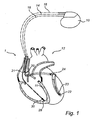
- FIG. 1 illustrates an implantable medical device (IMD), in the embodiments described below a cardiac stimulator 10, coupled to a heart 12.
- the implantable medical device may be a cardiac pacemaker, an implantable cardioverter defibrillator ("ICD"), a defibrillator, or an ICD coupled with a pacemaker implemented in accordance with embodiments of the present invention.
- ICD implantable cardioverter defibrillator
- the implantable medical device may be a dual-chamber stimulation device capable of treating both fast and slow arrhythmias with stimulation therapy, including cardioversion, defibrillation, and pacing stimulation, as well as capable of detecting heart failure, evaluating its severity, tracking the progression thereof, and controlling the delivery of therapy and warnings in response thereto.
- the IMD may monitor cardiac signals and based thereof, identify potentially abnormal physiology (e.g. ischemia).
- the detected cardiac signals may include intrinsic heart beats that have no assistance from any type of manmade electrical stimulation. Alternatively, the detected cardiac signals may include heart beats that have been stimulated by an electrical source to produce a paced heartbeat.
- the electrical source that provides low energy electrical signals such as provided by a pacemaker, a demand pacemaker, a single-chamber, a dual-chamber pacemaker, a biventricular pacemaker, and the like.
- the paced heartbeat may be generated by an implantable device that provides high energy electrical signals such as those provided by an implantable cardioverter defibrillator.
- the implantable cardiac stimulator 10 of the system 1 is in electrical communication with a patient's heart 12 by way of three leads 14, 16, and 18 suitable for delivering multichamber stimulation therapy.
- the stimulator 10 is coupled to an implantable right atrial lead 14 having, for example, an atrial tip electrode 20, which typically is implanted in the patient's right atrial appendage or septum.
- Fig. 1 shows the right atrial lead 14 as also having an atrial ring electrode 21.
- the stimulator 10 is coupled to a coronary sinus lead 16 designed for placement in the coronary sinus region via the coronary sinus for positioning a distal electrode adjacent to the left ventricle and/or additional electrode(s) adjacent to the left atrium.
- a coronary sinus lead 16 designed for placement in the coronary sinus region via the coronary sinus for positioning a distal electrode adjacent to the left ventricle and/or additional electrode(s) adjacent to the left atrium.
- coronary sinus region refers to the vasculature of the left ventricle, including any portion of the coronary sinus, great cardiac vein, left marginal vein, left posterior ventricular vein, middle cardiac vein, and/or small cardiac vein or any other cardiac vein accessible via the coronary sinus.
- the lead 16 is designed to receive atrial and ventricular cardiac signals and to deliver left ventricular pacing therapy using, for example, a left ventricular tip electrode 22, a left ventricular ring electrode 23, and left atrial pacing therapy using, for example, a left atrial ring electrode 24.
- the cardiac stimulator 10 is also in electrical communication with the heart 12 by way of an implantable right ventricular lead 18 having, in this embodiment, a right ventricular tip electrode 28 and a right ventricular ring electrode 30.
- the right ventricular lead 18 is transvenously inserted into the heart 12 to place the right ventricular tip electrode 28 in the right ventricular apex.
- the right ventricular lead 18 is capable of sensing or receiving cardiac signals, and delivering stimulation in the form of pacing therapy.
- the cardiac stimulator 10 may be used to collect cardiac signals (e.g. both intrinsic and paced heart beats). Initially, the cardiac stimulator 10 may collect baseline cardiac signals and programmable controller (e.g. processor) 41 (shown in Fig. 2 ) may determine ST segment variations for the baseline signals. The baseline cardiac signals and ST segment variations may be stored in memory 49 (shown in Fig. 2 ). The cardiac stimulator 10 may be reprogrammed by a programmer 54 (shown in Fig. 2 ) to adapt, for example, cardiac pacing settings. Further, the cardiac stimulator 10 may obtain cardiac signals (e.g. IEGM) on a beat-by-beat basis and store each heart in the memory 49.
- cardiac signals e.g. IEGM
- the cardiac stimulator 10 may store the time the heart beat occurred and the heart rate of the heart beat.
- the processor 41 may determine the ST segment variation associated with the heart beat and store the ST segment variation associated with the heart beat the ST segment value in memory 49 as will be described below.
- FIG. 2 an exemplary, simplified block diagram depicting various components of the cardiac stimulator according to embodiments of the present invention is shown.
- the cardiac stimulator 10 is capable of delivering cardiac resynchronization therapy and is configured to integrate both monitoring and therapy features, as will be described below. Further, the cardiac stimulator 10 collects and processes data about the heart 12 from electrode pairs for sensing cardiac electrogram (EGM) signals. While a particular multi-chamber device is shown, it is to be appreciated and understood that this is done for illustration purposes only. Thus, the techniques and methods described below can be implemented in connection with any suitable configured or configurable stimulation device. Accordingly, one of skill in the art could readily duplicate, eliminate, or disable the appropriate circuitry in any desired combination to provide a device capable of treating the appropriate chamber with pacing stimulation including cardiac resynchronisation therapy.
- EVM cardiac electrogram
- the cardiac stimulator 10 has a housing 40, often referred to as the "can” or “case electrode”.
- the housing 40 may function as a return electrode in "unipolar" modes.
- the housing 40 includes connector (not shown) having a plurality of terminals (not shown) for connection with electrodes and/or sensors.
- the cardiac stimulator 10 includes a programmable microcontroller or control module 41 that inter alia controls the various modes of stimulation therapy.
- the microcontroller 41 typically includes a microprocessor, or equivalent control circuitry, designed specifically for controlling the delivery of stimulation therapy and may further include RAM or ROM memory, logic and timing circuitry, state machine circuitry, and I/O circuitry.
- the microcontroller 41 includes the ability to process or monitor input signals (data or information) as controlled by a program stored in a designated block of memory.
- the type of microcontroller is not critical to the described implementations. Rather, any suitable microcontroller 41 may be used that carries out the functions described herein.
- the use of micro-processor based control circuits for performing timing and data analysis are well known in the art.
- the cardiac stimulator 10 includes pacing module 42 adapted to provide pacing signals for delivery to the patient.
- the pacing module 42 comprises an atrial pulse generator 43 and a ventricular pulse generator 44 that generate pacing stimulation pulses for delivery by the right atrial lead 14, the coronary sinus lead 16, and/or the right ventricular lead 18 via an electrode configuration switch 45.
- the atrial and ventricular pulse generators 43 and 44 may include dedicated, independent pulse generators, multiplexed pulse generators, or shared pulse generators.
- the pulse generators 43 and 44 are controlled by the microcontroller 41 via appropriate control signals to trigger or inhibit stimulation pulses.
- a data collection module 62 is adapted to collect, for example, cardiac signals such as IEGM signals. More specifically, the data collection module 62 is configured to collect IEGM signals, convert raw analog data into digital IEGM signals and store the digital IEGM signals in a memory for later processing or provide the digital IEGM signals to a data processing module 65 for preprocessing. Control signals from the microcontroller 41 determine when the data collection module 62 collects signals, stores them in the memory or transmit them to the data processing module 65. The data collection module 62 is coupled to the right atrial lead 14, the coronary sinus lead 16, and the right ventricular lead 18 to sample cardiac signals across any combination of electrodes.
- the data processing module 65 is configured to pre-process the received digital IEGM signals including a filtering process.
- a 2 nd order Bessel filter with limiting frequencies 2 Hz and 20 Hz is used.
- the signals may be filtered, reversed in the time domain, filtered again, and reversed in time again of the re-filtered signal. Thereby, the morphological changes induced by the filtering can be reduced and the time delays imposed by the filtering steps can be removed.
- a re-centering process may also be performed on the filtered signals including analyzing each heartbeat in a predetermined time window centered on an R-wave center, defined e.g.
- the signals are differentiated with respect to time thus providing a derivative IEGM signal.
- the derivative IEGM signal is thereafter provided to the microcontroller 41.
- the microcontroller 41 includes timing control circuitry 46 to control timing of the stimulation pulses (e.g. pacing rate, AV delay, VV delay, etc.) as well as to keep track of timing of refractory periods, blanking intervals, etc. which is well known in the art.
- the microcontroller 41 may include components such as e.g. an arrhythmia detector (not shown).
- the microcontroller 41 comprises a morphology detector 66 configured to detect and identify cardiac events in IEGM signals and/or derivative IEGM signals.
- the morphology detector 66 detects and identifies the R-wave for each heartbeat or cardiac cycle in the derivative IEGM signal.
- the morphology detector can also operate on the original IEGM signal for identifying R-Waves.
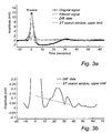
- Fig. 3a an original IEGM signal is shown together with the pre-processed signal (filtered) and the derivative signal. An ST search window is also shown. The R-wave is indicated in the diagram.
- a threshold determining module 67 is configured to determine a threshold used for identifying the ST windows. According to an embodiment of the present invention, the threshold is determined as follows:
- the threshold may be set to a higher value in an area close to the R-wave.
- the threshold is set to be higher at the start and lower at the end.
- the threshold is linearly decreasing from the starting point to the end point.
- the start value is a first multiplying factor (e.g. 1.5, 2, 2.2 or 2.5) times the 30 th percentile value and the end value is a second multiplying factor (e.g. 1 ⁇ 4, 1/3, 1 ⁇ 2 or 3 ⁇ 4) of the 30 th percentile value.
- first multiplying factor e.g. 1.5, 2, 2.2 or 2.5
- the end value is a second multiplying factor (e.g. 1 ⁇ 4, 1/3, 1 ⁇ 2 or 3 ⁇ 4) of the 30 th percentile value.
- the rectified derivative IEGM signal is shown together with a linearly decreasing threshold.
- the length of the threshold coincides with ST search window in this case.
- the period starting at 7 and ending at 16 samples is found to be the ST window for this heartbeat.
- other shapes of the decreasing threshold can also be used, e.g. quadric, exponential, logarithmic, step-wise etc.
- an ST window determining module 68 is configured to analyze the derivative signal data following the identified R-wave so as to find portions of the derivative signal comprising samples having lower values than the predetermined threshold.
- the ST window determining module 68 is configured to determine a portion of the derivative signal including samples having lower values than the threshold to correspond to a ST window for that cardiac cycle if that portion fulfills predetermined requirements. According to embodiments of the present invention, the following requirements have to be fulfilled:
- the ST window determining module 68 may further be configured to perform a verification procedure to verify parameters of the overall ST window, i.e. starting point, duration and end point.
- the starting point, duration and end point are therefore analyzed to verify that they are within allowed ranges. If not, the parameters can be adjusted to fit into the ranges, or they can be recalculated.
- the ranges are the following:
- An ischemia detection module 69 is configured to use the overall ST window as a reference ST window in detecting ischemia by comparing IEGM data in the reference ST window with current IEGM data from a segment of the IEGM signal corresponding to the reference ST window. By comparing the reference ST window with current IEGM data in the corresponding window, shifts in the ST segment can be monitored, which are an indicator of a potential abnormal physiology, such as, ischemia.
- the aforementioned components may be implemented as part of the microcontroller 41, or as softwarelfirmware instructions programmed into the device and executed on the microcontroller 41 during certain modes of operation.
- Several of the components discussed above such as the threshold determining module 67, the ST determining module 68 and the ischemia detection module may be implemented in an extracorporal device such as a programmer. In fact there are several different possibilities to split components between the cardiac stimulator and the external instrument.
- the cardiac stimulator 10 additionally includes a battery 58 that provides operating power to all of the circuits shown in Fig. 2 .
- the stimulator 10 employs lithium or similar battery technology.
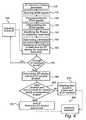
- FIG. 4 is a flow diagram of a ST window generation process 100, which may be performed by a cardiac stimulator configured in accordance with an example embodiment of the inventions, for example, as illustrated in Fig. 2 .
- the various tasks performed in connection with the process 100 may be performed by software, hardware, firmware, or any combination thereof.
- the following description of the process 100 refers to elements mentioned above in connection with Figs. 1 - 2 .
- portions of the process 100 may be performed by different elements of the described cardiac stimulator.
- the process 100 may include any number of additional or alternative tasks, the tasks shown in Fig. 4 need not be performed in the illustrated order, and the process 100 may be incorporated into a more comprehensive procedure or process having additional functionality not described in detail herein.
- the process 100 obtains at least one IEGM signal indicating cardiac behavior of a cardiac cycle corresponding a heartbeat, in task 110, using the data collection module 62 which is configured to obtain data about the patient.
- the IEGM signals are pre-processed in task 120 by the data processing module 65.
- the signals may be re-centered and filtered, e.g. by using a 2 nd order Bessel filter with limiting frequencies 2 Hz and 20 Hz as have been described above.
- the IEGM signals are differentiated with respect to time in the data processing module 65.
- the R-wave is identified in the derivative signal for respective heart beat in the morphology detector 66.
- the R-wave can also be identified by analyzing the original IEGM-signal, for example through amplitude comparison with a predetermined value.
- the threshold determining module 67 determines a threshold used for identifying the ST windows in task 150 as has been described above. To reduce the risk of having an ST window that starts too far away from the R-wave and/or too close to the T-wave, the threshold may be set to a higher value in an area close to the R-wave. Thus, the threshold is set to be higher at the start and lower at the end as has been described above.
- the differentiated IEGM signal for respective heart beat is analyzed by the ST window determining module 68.
- a signal portion following the identified R-wave is analyzed so as to find portions of the signal that comprises samples having lower values than a predetermined threshold.
- a portion of the differentiated signal for a cardiac cycle including samples having lower values than the threshold is determined to correspond to an ST window for that cardiac cycle if that portion fulfills predetermined requirements, which according to an embodiment of the present invention are:
- query task 170 it is checked whether enough ST windows have been found in the analysis, for example, more than 50%, 60% or 65% of the heart beats. Hence, it is checked that the number of ST windows found in relation to the total number of heart beats is not too low. If the number of identified ST windows is too low, the process 100 proceeds to task 180 where the threshold is adjusted to a higher value, i.e. the threshold is increased. Then, task 160 is repeated but with the adjusted threshold. Preferably, the present threshold is multiplied with 2, which entails that the inclination of the threshold is preserved. Another alternative is to change the percentile value or any other parameter that controls the threshold, in such a case the process 100 is repeated from task 150 instead.
- an overall ST window start point and ST window duration are determined based on all identified ST windows.
- the median of all start points and durations are calculated while ignoring the heart beats for which a ST window could not be determined. It is however also possible to calculate, for example, the average of one or more percentiles, a weighted average.
- a verification of the determined start point and duration is performed in task 200.
- the ST window start point, the ST window duration and ST window end point are analyzed to check whether they fall within allowed ranges. If the start point, duration and/or end point fall outside predetermined ranges (discussed above), an adjustment is performed in task 210. For example, if the ST window start value is smaller than the lowest allowed value, it is changed to this lowest allowed value. In an alternative embodiment, the process 100 returns to task 150 for a new calculation of ST windows before the adjustment in task 210 is performed. If the overall ST window is approved, i.e. the start value, duration and end value are within the predetermined ranges, the process is finished and the overall ST window is ready for use as a reference ST window in, for example, ischemia detection in an ischemia detection process 300.
Description
- The present invention relates generally to implantable medical devices and more particularly to systems and methods for automatically determining ST windows for ischemia detection.
- Many patients at risk of cardiac ischemia have pacemakers, ICDs or other medical devices implanted therein. Cardiac ischemia is a severe condition and great efforts has therefore been made within the medical community to find systems and methods for detecting and monitoring ischemia over time. Electrocardiograms (ECG) are useful for diagnosing ischemia and locate damaged areas within the heart. Cardiac ischemia is a condition whereby heart tissue does not receive adequate amounts of oxygen and is usually caused by a blockage of an artery leading to damage of heart tissue. ECGs are composed of various waves and segments that represent the heart depolarization and repolarization. The ST segment represent the portion of the cardiac signal between ventricular depolarization and ventricular repolarization.
- In the prior art, there exist techniques for detecting cardiac ischemia using implanted medical devices. In some conventional IEGM-based ischemia detection techniques, changes in the elevation or depression of the ST segment from a IEGM baseline are used an indication of ischemia. Elevation or depression of the ST segment in an IEGM signal may be the result of abnormalities in the polarization of cardiac tissue during an acute myocardial infraction (MI). An ST segment shift arises because the differences in the electric potential between cells that have become ischemic and those cells are still receiving normal blood flow. Deviation of an ST segment from a baseline is a result of an injury to the cardiac muscle, changes in the synchronization of ventricular muscle depolarization, drug or electrolyte influences, or the like.
- In some prior art methods for determining ST window for ischemia detection, the ST window is a fixed time interval relative the R-wave. This may lead to that the ST window may encompass parts of the T-wave or the R-wave. If changes occur to the amplitude of the T-wave or R-wave, this may result in a false indication of an ST episode. Accordingly, there is a need of improving the specificity of these prior art methods. Such improvement can be achieved by allowing manual adjustments of the default parameters defining e.g. the fixed time interval to adapt the parameters to a specific patient.
- In
US Pat. Appl. 7,865,232 to Krishnaswamy et al., a method and system for automatically determining ischemia detection parameters is disclosed. An ischemia detection window is based on physiological state indicators that define start and end of the ischemia detection window. The physiological state indicators can be located by identifying slope changes after the R-wave and before the T-wave, respectively. Slope changes are recognized by identifying when the derivative of the composite intrinsic baseline changes sign from positive to negative or vice versa following the R-wave marker. The slope changes are used to locate ischemia detection parameters (e.g. start and end of ST window). A first ischemia detection parameter (indicating the start of the ST window) can be identified as a point along the baseline following the first slope change but with a predetermined offset (e.g. about 25 msec). A second ischemia detection parameter (indicating the end of the ST window) can be identified as a point along the baseline preceding the third slope change with a negative offset (e.g. about 35 msec). -
US 2011/0040200 A1 discloses a system for analyzing an ECG signal. One out of two isoelectric portions in the ECG signal is adaptively selected for a heart beat cycle as a baseline based on stability measures. A point of reference of an ST segments in the heart beat cycle is determined. A deviation of the point of reference on the ST segment from the selected baseline is evaluated. -
US 2008/0058881 A1 discloses an implantable device for delivering phototherapy for treatment of post-MI patients. -
US 2007/0150015 A1 discloses a cardiac device with the capability of detecting cardiac ischemia using multiple sensing modalities. - However, there is still a need within the art for a patient-specific determination of ST windows or segments for use in ischemia detection in order to inter alia improve the specificity of the ischemia detection.
- An object of the present invention is to provide systems for improving the specificity of the ischemia detection.
- Another object of the present invention is to provide systems for automatically determining ST windows for use in ischemia detection.
- These and other objects of the present invention are achieved by means of an implantable medical device having the features defined in the independent claims. Embodiments of the invention are characterized by the dependent claims.
- There is provided a method for ischemia detection not forming part of the current invention, comprising obtaining at least one IEGM signal representative of cardiac behavior of a patient over a period of time and calculating a derivative signal of the IEGM signal. The R-wave is identified in the derivative signal or in the original IEGM signal and data of the derivative signal following the identified R-wave is analyzed so as to find portions of the derivative signal comprising samples having lower values than a predetermined threshold. Further, a portion of the derivative signal including samples having lower values than the threshold is determined to correspond to a ST window for that cardiac cycle if that portion fulfills predetermined requirements. A reference ST window based on a number of determined ST windows is determined. Using the reference ST window, ischemia can be detected by comparing IEGM data in the reference ST window with current IEGM data from a segment of the IEGM signal corresponding to the reference ST window. A shift in the ST segment, i.e. the portion of the signal in the ST window, from a baseline or reference level is an indication of cardiac ischemia. For example, a depression of the IEGM signal in the ST window may be an indication of cardiac ischemia. Deviation of the ST segment from a baseline may be a result of an injury to cardiac muscle arising from differences in electric potential between cells that have become ischemic and those cells still receiving normal blood flow.
- According to an aspect of the present invention, there is provided a system for ischemia detection comprising a data collection module configured to obtain at least one IEGM signal indicating cardiac behavior of a cardiac cycle corresponding a heartbeat and a data processing module configured to calculate a derivative signal of the IEGM signal. Furthermore, the system comprises a morphology detector configured to identify an R-wave in the derivative signal or in the original IEGM signal and an ST window determining module. The ST window determining module is configured to analyze the derivative signal data following the identified R-wave so as to find portions of the derivative signal comprising samples having lower values than a predetermined threshold, determine a portion of the derivative signal including samples having lower values than the threshold to correspond to a ST window for that cardiac cycle if that portion fulfills predetermined requirements and create a reference ST window based on a number of determined ST windows. An ischemia detection module is configured to detect ischemia by comparing IEGM data in the reference ST window with current IEGM data from a segment of the IEGM signal corresponding to the reference ST window.
- In preferred embodiments of the present invention, all or some modules of the system are implemented in an implantable medical device or cardiac stimulator such as a cardiac pacemaker (a dual or single chamber stimulation device), an implantable cardioverter defibrillator ("ICD"), a defibrillator, or an ICD coupled with a pacemaker.
- In a further embodiment some modules are implemented in an extracorporal device such as a programmer. The collected IEGM signals may be stored in a memory. Examples of modules that may be located in a programmer that analyzes stored IEGM data that may be read out from a memory are the ST window determining module or the ischemia detection module. The division of modules for implementing the system may be made in several different ways.
- According to embodiments of the present invention, the threshold is determined based on derivative signal data following the identified R-wave, such that the threshold is higher in a region following the R-wave. By making the threshold higher near the R-wave, the risk that a start point of an ST window is set to be too far away from the R-wave and/or too close to the T-wave can be significantly reduced. Preferably, the threshold is set to be linearly decreasing from the R-wave, for example, the peak value of the R-wave. Other shapes of the decreasing threshold can also be used, for example, quadratic, exponential, logarithmic, or step-wise. According to an embodiment of the present invention, the threshold has a value at a starting point of a search window being a multiple of the value of the threshold base sample and a value at an end point of the search window being lower than the value of the threshold base sample, wherein the threshold is linearly decreasing between the value of the starting point and the end point.
- The predetermined requirements for determining a portion of the derivative signal to be a ST window comprises that:
- a predetermined number of samples in the portion has a value below the predetermined threshold;
- a predetermined number of samples having values below the threshold are consecutive; and
- the portion has a length exceeding a predetermined time interval.
- According to embodiments of the present invention, the requirements for determining a portion of the derivative signal to be a ST window further comprises, if more than one portion fulfill the predetermined requirements to correspond to a ST window for that cardiac cycle, selecting the portion being closest to the R-wave to correspond to the ST window for that cardiac cycle.
- An overall ST window is created by: identifying a predetermined number of ST windows, determining a starting point of the reference ST window based on starting points for the gathered ST windows, and determining an end point of the reference ST window based on end points for the gathered ST windows.
- According to embodiments of the present invention, the sensitivity of the threshold is adjusted if a predetermined number of ST windows has not been identified during a predetermined period of time or from of a predetermined number of cardiac cycles. Thereafter, the derivative signal data following the identified R-wave is analyzed for each cardiac cycle so as to find portions of the derivative signal comprising samples having lower values than the adjusted threshold and a portion of the derivative signal including samples having lower values than the adjusted threshold is determined to correspond to an ST window for that cardiac cycle if that portion fulfills predetermined requirements.
- Further objects and advantages of the present invention will be discussed below by means of exemplifying embodiments.
- These and other features, aspects and advantages of the invention will be more fully understood when considered with respect to the following detailed description, appended claims and accompanying drawings.
- The drawings are not necessarily drawn to scale and illustrate generally, by way of example, but no way of limitation, various embodiments of the present invention. Thus, exemplifying embodiments of the invention are illustrated by way of example and not by way of limitation in the figures of the accompanying drawings in which like references indicate similar elements. It should be noted that references to "an" or "one" embodiment in this discussion are not necessarily to the same embodiment, and such references mean at least one.
-
Fig. 1 is a simplified and schematic diagram of one embodiment of a system configuration according to the present invention including an implantable stimulation device in electrical communication with several leads implanted in a patient's heart for detecting cardiac activity and for delivering multi-chamber stimulation; -
Fig. 2 is a simplified functional block diagram of one embodiment of a system in accordance with the present invention, illustrating basic elements of the system; -
Fig. 3a is a diagram showing original IEGM signal, the pre-processed signal, the rectified derivative IEGM signal, and ST threshold (coinciding with the ST search window). The period starting at 7 and ending at 16 samples is found to be the ST window for this heartbeat; -
Fig. 3b is a diagram showing the rectified derivative IEGM signal and the threshold superimposed ofFig. 3a in more detail. The length of the threshold coincides with the ST search window. The period starting at 7 and ending at 16 samples is found to be the ST window for this heartbeat; and -
Fig. 4 is a flow diagram of an ST window determining process, which may be performed by a cardiac stimulator configured in accordance with example embodiments of the invention. - The following is a description of exemplifying embodiments in accordance with the present invention. Embodiments may be used with a pacemaker, a cardioverter, a defibrillator, and the like.
- Referring to
Fig. 1 , one implementation of the present invention relating to a system including an implantable cardiac stimulator connectable to one or more medical leads will be discussed.Fig. 1 illustrates an implantable medical device (IMD), in the embodiments described below acardiac stimulator 10, coupled to aheart 12. The implantable medical device may be a cardiac pacemaker, an implantable cardioverter defibrillator ("ICD"), a defibrillator, or an ICD coupled with a pacemaker implemented in accordance with embodiments of the present invention. The implantable medical device may be a dual-chamber stimulation device capable of treating both fast and slow arrhythmias with stimulation therapy, including cardioversion, defibrillation, and pacing stimulation, as well as capable of detecting heart failure, evaluating its severity, tracking the progression thereof, and controlling the delivery of therapy and warnings in response thereto. As explained below in more detail, the IMD may monitor cardiac signals and based thereof, identify potentially abnormal physiology (e.g. ischemia). The detected cardiac signals may include intrinsic heart beats that have no assistance from any type of manmade electrical stimulation. Alternatively, the detected cardiac signals may include heart beats that have been stimulated by an electrical source to produce a paced heartbeat. The electrical source that provides low energy electrical signals, such as provided by a pacemaker, a demand pacemaker, a single-chamber, a dual-chamber pacemaker, a biventricular pacemaker, and the like. Optionally, the paced heartbeat may be generated by an implantable device that provides high energy electrical signals such as those provided by an implantable cardioverter defibrillator. - The implantable
cardiac stimulator 10 of thesystem 1 is in electrical communication with a patient'sheart 12 by way of three leads 14, 16, and 18 suitable for delivering multichamber stimulation therapy. - To sense atrial signals and to provide right atrial chamber stimulation therapy, the
stimulator 10 is coupled to an implantable rightatrial lead 14 having, for example, anatrial tip electrode 20, which typically is implanted in the patient's right atrial appendage or septum.Fig. 1 shows the rightatrial lead 14 as also having anatrial ring electrode 21. - To sense left atrial and ventricular cardiac signals and to provide left chamber pacing therapy the
stimulator 10 is coupled to acoronary sinus lead 16 designed for placement in the coronary sinus region via the coronary sinus for positioning a distal electrode adjacent to the left ventricle and/or additional electrode(s) adjacent to the left atrium. As used herein, the phrase "coronary sinus region" refers to the vasculature of the left ventricle, including any portion of the coronary sinus, great cardiac vein, left marginal vein, left posterior ventricular vein, middle cardiac vein, and/or small cardiac vein or any other cardiac vein accessible via the coronary sinus. - The
lead 16 is designed to receive atrial and ventricular cardiac signals and to deliver left ventricular pacing therapy using, for example, a leftventricular tip electrode 22, a leftventricular ring electrode 23, and left atrial pacing therapy using, for example, a leftatrial ring electrode 24. - The
cardiac stimulator 10 is also in electrical communication with theheart 12 by way of an implantableright ventricular lead 18 having, in this embodiment, a rightventricular tip electrode 28 and a rightventricular ring electrode 30. Typically, theright ventricular lead 18 is transvenously inserted into theheart 12 to place the rightventricular tip electrode 28 in the right ventricular apex. Theright ventricular lead 18 is capable of sensing or receiving cardiac signals, and delivering stimulation in the form of pacing therapy. - The
cardiac stimulator 10 may be used to collect cardiac signals (e.g. both intrinsic and paced heart beats). Initially, thecardiac stimulator 10 may collect baseline cardiac signals and programmable controller (e.g. processor) 41 (shown inFig. 2 ) may determine ST segment variations for the baseline signals. The baseline cardiac signals and ST segment variations may be stored in memory 49 (shown inFig. 2 ). Thecardiac stimulator 10 may be reprogrammed by a programmer 54 (shown inFig. 2 ) to adapt, for example, cardiac pacing settings. Further, thecardiac stimulator 10 may obtain cardiac signals (e.g. IEGM) on a beat-by-beat basis and store each heart in thememory 49. In addition, associated with each heart beat, thecardiac stimulator 10 may store the time the heart beat occurred and the heart rate of the heart beat. Theprocessor 41 may determine the ST segment variation associated with the heart beat and store the ST segment variation associated with the heart beat the ST segment value inmemory 49 as will be described below. - In
Fig. 2 , an exemplary, simplified block diagram depicting various components of the cardiac stimulator according to embodiments of the present invention is shown. Thecardiac stimulator 10 is capable of delivering cardiac resynchronization therapy and is configured to integrate both monitoring and therapy features, as will be described below. Further, thecardiac stimulator 10 collects and processes data about theheart 12 from electrode pairs for sensing cardiac electrogram (EGM) signals. While a particular multi-chamber device is shown, it is to be appreciated and understood that this is done for illustration purposes only. Thus, the techniques and methods described below can be implemented in connection with any suitable configured or configurable stimulation device. Accordingly, one of skill in the art could readily duplicate, eliminate, or disable the appropriate circuitry in any desired combination to provide a device capable of treating the appropriate chamber with pacing stimulation including cardiac resynchronisation therapy. - The
cardiac stimulator 10 has ahousing 40, often referred to as the "can" or "case electrode". Thehousing 40 may function as a return electrode in "unipolar" modes. Further, thehousing 40 includes connector (not shown) having a plurality of terminals (not shown) for connection with electrodes and/or sensors. - The
cardiac stimulator 10 includes a programmable microcontroller orcontrol module 41 that inter alia controls the various modes of stimulation therapy. As well known within the art, themicrocontroller 41 typically includes a microprocessor, or equivalent control circuitry, designed specifically for controlling the delivery of stimulation therapy and may further include RAM or ROM memory, logic and timing circuitry, state machine circuitry, and I/O circuitry. Typically, themicrocontroller 41 includes the ability to process or monitor input signals (data or information) as controlled by a program stored in a designated block of memory. The type of microcontroller is not critical to the described implementations. Rather, anysuitable microcontroller 41 may be used that carries out the functions described herein. The use of micro-processor based control circuits for performing timing and data analysis are well known in the art. - Furthermore, the
cardiac stimulator 10 includes pacingmodule 42 adapted to provide pacing signals for delivery to the patient. Thepacing module 42 comprises anatrial pulse generator 43 and aventricular pulse generator 44 that generate pacing stimulation pulses for delivery by the rightatrial lead 14, thecoronary sinus lead 16, and/or theright ventricular lead 18 via anelectrode configuration switch 45. It is understood that in order to provide stimulation therapy in each of the four chambers, the atrial andventricular pulse generators pulse generators microcontroller 41 via appropriate control signals to trigger or inhibit stimulation pulses. - A
data collection module 62 is adapted to collect, for example, cardiac signals such as IEGM signals. More specifically, thedata collection module 62 is configured to collect IEGM signals, convert raw analog data into digital IEGM signals and store the digital IEGM signals in a memory for later processing or provide the digital IEGM signals to adata processing module 65 for preprocessing. Control signals from themicrocontroller 41 determine when thedata collection module 62 collects signals, stores them in the memory or transmit them to thedata processing module 65. Thedata collection module 62 is coupled to the rightatrial lead 14, thecoronary sinus lead 16, and theright ventricular lead 18 to sample cardiac signals across any combination of electrodes. - The
data processing module 65 is configured to pre-process the received digital IEGM signals including a filtering process. In one embodiment of the present invention, a 2nd order Bessel filter with limitingfrequencies 2 Hz and 20 Hz is used. Further, the signals may be filtered, reversed in the time domain, filtered again, and reversed in time again of the re-filtered signal. Thereby, the morphological changes induced by the filtering can be reduced and the time delays imposed by the filtering steps can be removed. A re-centering process may also be performed on the filtered signals including analyzing each heartbeat in a predetermined time window centered on an R-wave center, defined e.g. by the AnalyST™ algorithm provided by the applicant, where the greatest positive deflection is redefined as the heartbeat center. Moreover, the signals are differentiated with respect to time thus providing a derivative IEGM signal. The derivative IEGM signal is thereafter provided to themicrocontroller 41. - The
microcontroller 41 includestiming control circuitry 46 to control timing of the stimulation pulses (e.g. pacing rate, AV delay, VV delay, etc.) as well as to keep track of timing of refractory periods, blanking intervals, etc. which is well known in the art. In addition, themicrocontroller 41 may include components such as e.g. an arrhythmia detector (not shown). - The
microcontroller 41 comprises amorphology detector 66 configured to detect and identify cardiac events in IEGM signals and/or derivative IEGM signals. - The
morphology detector 66 detects and identifies the R-wave for each heartbeat or cardiac cycle in the derivative IEGM signal. The morphology detector can also operate on the original IEGM signal for identifying R-Waves. - In
Fig. 3a , an original IEGM signal is shown together with the pre-processed signal (filtered) and the derivative signal. An ST search window is also shown. The R-wave is indicated in the diagram. - A
threshold determining module 67 is configured to determine a threshold used for identifying the ST windows. According to an embodiment of the present invention, the threshold is determined as follows: - All samples in the window to be analyzed following the R-wave are extracted.
- The 30th percentile value among these samples is identified. This is a preferred value and can be adapted to, for example, a specific patient.
- The 30th percentile value is set as the threshold value.
- To reduce the risk of having a ST window that starts too far away from the R-wave and/or too close to the T-wave, the threshold may be set to a higher value in an area close to the R-wave. Thus, the threshold is set to be higher at the start and lower at the end. In a preferred embodiment of the present invention, the threshold is linearly decreasing from the starting point to the end point. In a preferred embodiment of the present invention, the start value is a first multiplying factor (e.g. 1.5, 2, 2.2 or 2.5) times the 30th percentile value and the end value is a second multiplying factor (e.g. ¼, 1/3, ½ or ¾) of the 30th percentile value. In
Fig. 3b , the rectified derivative IEGM signal is shown together with a linearly decreasing threshold. The length of the threshold coincides with ST search window in this case. The period starting at 7 and ending at 16 samples is found to be the ST window for this heartbeat. However, other shapes of the decreasing threshold can also be used, e.g. quadric, exponential, logarithmic, step-wise etc. - Furthermore, an ST
window determining module 68 is configured to analyze the derivative signal data following the identified R-wave so as to find portions of the derivative signal comprising samples having lower values than the predetermined threshold. The STwindow determining module 68 is configured to determine a portion of the derivative signal including samples having lower values than the threshold to correspond to a ST window for that cardiac cycle if that portion fulfills predetermined requirements. According to embodiments of the present invention, the following requirements have to be fulfilled: - i) The derivative of a sample is lower than the threshold.
- ii) All samples matching i) are consecutive with the exception of a gap of a preset length (in a preferred embodiment a gap of 7.8 ms = 1 sample at 128 Hz is tolerated)
- iii) The portion of the derivative signal having such consecutive samples below the threshold is longer than a minimum allowed ST window. In a preferred embodiment, the minimum length is about 20 - 30 ms, and in more preferred embodiment the minimum length is about 25 ms.
- The ST
window determining module 68 may further be configured to perform a verification procedure to verify parameters of the overall ST window, i.e. starting point, duration and end point. The starting point, duration and end point are therefore analyzed to verify that they are within allowed ranges. If not, the parameters can be adjusted to fit into the ranges, or they can be recalculated. According to an embodiment of the present invention, the ranges are the following: - The minimum allowed ST start value from the R-wave, for example, from the peak value of the R-wave is between 15 - 80 ms, and is preferably between 20 - 60 ms, and more preferably between 20 - 30 ms. An example of a minimum ST start value is 24 ms from the R-wave, for example, from the peak value of the R-wave. Another example minimum start value is 40 ms from the R-wave, for example, from the peak value of the R-wave.
- The maximum allowed ST start value from the R-wave, for example, from the peak value of the R-wave is between 50 - 300 ms, and preferably between 100 - 280 ms, and more preferably between 200 - 270 ms. An example of a maximum ST start value is 250 ms from the R-wave, for example, from the peak value of the R-wave. Another example of the maximum start value is 110 ms from the R-wave, for example, from the peak value of the R-wave.
- The maximum ST end time from the R-wave, for example, from the peak value of the R-wave is between 200 - 300 ms, and preferably between 220 - 290 ms, and more preferably between 250 - 280 ms. An example of a maximum ST end time is 274 ms from the R-wave, for example, from the peak value of the R-wave.
- A maximum duration value may also be applied, for example, between 30 - 90 ms, or preferably between 40 - 80 ms, or more preferably between 50 - 70 ms. In one specific embodiment, the maximum duration value is about 60 ms.
- An
ischemia detection module 69 is configured to use the overall ST window as a reference ST window in detecting ischemia by comparing IEGM data in the reference ST window with current IEGM data from a segment of the IEGM signal corresponding to the reference ST window. By comparing the reference ST window with current IEGM data in the corresponding window, shifts in the ST segment can be monitored, which are an indicator of a potential abnormal physiology, such as, ischemia. - The aforementioned components may be implemented as part of the
microcontroller 41, or as softwarelfirmware instructions programmed into the device and executed on themicrocontroller 41 during certain modes of operation. Several of the components discussed above such as thethreshold determining module 67, theST determining module 68 and the ischemia detection module may be implemented in an extracorporal device such as a programmer. In fact there are several different possibilities to split components between the cardiac stimulator and the external instrument. - Moreover, the
cardiac stimulator 10 additionally includes abattery 58 that provides operating power to all of the circuits shown inFig. 2 . Preferably, thestimulator 10 employs lithium or similar battery technology. - With reference now to
Fig. 4 , an embodiment of the method for generating a patient specific ST window not forming part of the current invention, will be discussed.Fig. 4 is a flow diagram of a STwindow generation process 100, which may be performed by a cardiac stimulator configured in accordance with an example embodiment of the inventions, for example, as illustrated inFig. 2 . The various tasks performed in connection with theprocess 100 may be performed by software, hardware, firmware, or any combination thereof. For illustrative purposes, the following description of theprocess 100 refers to elements mentioned above in connection withFigs. 1 - 2 . In practical embodiments, portions of theprocess 100 may be performed by different elements of the described cardiac stimulator. It should be appreciated that theprocess 100 may include any number of additional or alternative tasks, the tasks shown inFig. 4 need not be performed in the illustrated order, and theprocess 100 may be incorporated into a more comprehensive procedure or process having additional functionality not described in detail herein. - The
process 100 obtains at least one IEGM signal indicating cardiac behavior of a cardiac cycle corresponding a heartbeat, intask 110, using thedata collection module 62 which is configured to obtain data about the patient. - The IEGM signals are pre-processed in
task 120 by thedata processing module 65. For example, the signals may be re-centered and filtered, e.g. by using a 2nd order Bessel filter with limitingfrequencies 2 Hz and 20 Hz as have been described above. - In
task 130, the IEGM signals are differentiated with respect to time in thedata processing module 65. - Thereafter, in
task 140, the R-wave is identified in the derivative signal for respective heart beat in themorphology detector 66. The R-wave can also be identified by analyzing the original IEGM-signal, for example through amplitude comparison with a predetermined value. - The
threshold determining module 67 determines a threshold used for identifying the ST windows intask 150 as has been described above. To reduce the risk of having an ST window that starts too far away from the R-wave and/or too close to the T-wave, the threshold may be set to a higher value in an area close to the R-wave. Thus, the threshold is set to be higher at the start and lower at the end as has been described above. - In
task 160, the differentiated IEGM signal for respective heart beat is analyzed by the STwindow determining module 68. Preferably, a signal portion following the identified R-wave is analyzed so as to find portions of the signal that comprises samples having lower values than a predetermined threshold. A portion of the differentiated signal for a cardiac cycle including samples having lower values than the threshold is determined to correspond to an ST window for that cardiac cycle if that portion fulfills predetermined requirements, which according to an embodiment of the present invention are: - (i) The derivative of a sample is lower than the threshold,
- (ii) All samples matching i) are consecutive with the exception of a gap of a predetermined length (in a preferred embodiment a gap of 7.8 ms = 1 sample at 128 Hz is tolerated), and
- (iii) The portion of the derivative signal having such consecutive samples below the threshold is longer than a minimum allowed ST window. In a preferred embodiment, the minimum length is about 20 - 30 ms, and in more preferred embodiment the minimum length is about 25 ms.
- In
query task 170, it is checked whether enough ST windows have been found in the analysis, for example, more than 50%, 60% or 65% of the heart beats. Hence, it is checked that the number of ST windows found in relation to the total number of heart beats is not too low. If the number of identified ST windows is too low, theprocess 100 proceeds totask 180 where the threshold is adjusted to a higher value, i.e. the threshold is increased. Then,task 160 is repeated but with the adjusted threshold. Preferably, the present threshold is multiplied with 2, which entails that the inclination of the threshold is preserved. Another alternative is to change the percentile value or any other parameter that controls the threshold, in such a case theprocess 100 is repeated fromtask 150 instead. However, if enough ST windows have been found, theprocess 100 continues to task 190 where an overall ST window start point and ST window duration are determined based on all identified ST windows. In a preferred embodiment, the median of all start points and durations are calculated while ignoring the heart beats for which a ST window could not be determined. It is however also possible to calculate, for example, the average of one or more percentiles, a weighted average. - When the overall ST window start point and ST window duration have been determined, a verification of the determined start point and duration is performed in
task 200. The ST window start point, the ST window duration and ST window end point are analyzed to check whether they fall within allowed ranges. If the start point, duration and/or end point fall outside predetermined ranges (discussed above), an adjustment is performed intask 210. For example, if the ST window start value is smaller than the lowest allowed value, it is changed to this lowest allowed value. In an alternative embodiment, theprocess 100 returns totask 150 for a new calculation of ST windows before the adjustment intask 210 is performed. If the overall ST window is approved, i.e. the start value, duration and end value are within the predetermined ranges, the process is finished and the overall ST window is ready for use as a reference ST window in, for example, ischemia detection in anischemia detection process 300.
Claims (7)
- A system (1) for ischemia detection comprising:a data collection module (62) configured to obtain at least one IEGM signal indicating cardiac behavior of a cardiac cycle corresponding to a heartbeat;a data processing module (65) configured to calculate a derivative signal of the IEGM signal;a detector (66) configured to identify a R-wave in the derivative signal or in the IEGM signal, characterized by:an ST window determining module (68) configured to:analyze said derivative signal data following said identified R-wave so as to find portions of said derivative signal comprising samples having lower values than a predetermined threshold;determine a portion of said derivative signal including samples having lower values than said threshold to correspond to a ST window for that cardiac cycle if that portion fulfills predetermined requirements comprising:a predetermined number of samples in said portion has a value below said predetermined threshold;a predetermined number of samples having values below said threshold are consecutive; andthe portion has a length exceeding a predetermined time interval; andcreate a reference ST window based on a number of determined ST windows; andan ischemia detection module (69) configured to detect ischemia by comparing IEGM data in said reference ST window with current IEGM data from a segment of a current IEGM signal corresponding to the reference ST window.
- The system according to claim 1, further comprising a threshold determining module (67) configured to determine said threshold based on derivative signal data following said identified R-wave, said threshold having a higher value in a region following said R-wave.
- The system according to claim 2, wherein said threshold determining module (67) is further configured to find a threshold base sample having a value that is equal to a 30th percentile value among samples in said derivative signal in a search window following said R-wave.
- The system according to claim 2 or 3, wherein said threshold determining module (67) is further configured to determine a value of a starting point of a search window to be a multiple of said value of said threshold base sample and a value at an end point of said search window to be lower than said value of said threshold base sample, wherein said threshold is linearly decreasing between the value of the starting point and said end point.
- The system according to any one of the preceding claims , wherein said requirements for determining a portion of the derivative signal to be a ST window further comprises, if more than one portion fulfill said predetermined requirements to correspond to a ST window for that cardiac cycle, selecting the portion being closest to the R-wave to correspond to the ST window for that cardiac cycle.
- The system according to any one of preceding claims, wherein said ST window determining module (68) is further configured to:identify a predetermined number of ST windows;determine a starting point of the reference ST window based on starting points for said determined ST windows; anddetermine an end point of the reference ST window based on end points for said determined ST windows.
- The system according to claim 6, wherein said threshold determining module (68) is further configured to, if a predetermined number of ST windows has not been identified during a predetermined period of time or from of a predetermined number of cardiac cycles, adjust said threshold to a higher value; and wherein said ST window determining module (68) is further configured to:analyze said derivative signal data following said identified R-wave for each cardiac cycle so as to find portions of said derivative signal comprising samples having lower values than said adjusted threshold; anddetermine a portion of said derivative signal including samples having lower values than said threshold to correspond to a ST window for that cardiac cycle if that portion fulfills predetermined requirements.
Priority Applications (2)
| Application Number | Priority Date | Filing Date | Title |
|---|---|---|---|
| EP11170536.4A EP2537460B1 (en) | 2011-06-20 | 2011-06-20 | Method and system for ischemia detection |
| US13/528,695 US8577449B2 (en) | 2011-06-20 | 2012-06-20 | Method and system for ischemia detection |
Applications Claiming Priority (1)
| Application Number | Priority Date | Filing Date | Title |
|---|---|---|---|
| EP11170536.4A EP2537460B1 (en) | 2011-06-20 | 2011-06-20 | Method and system for ischemia detection |
Publications (2)
| Publication Number | Publication Date |
|---|---|
| EP2537460A1 EP2537460A1 (en) | 2012-12-26 |
| EP2537460B1 true EP2537460B1 (en) | 2015-01-07 |
Family
ID=44910337
Family Applications (1)
| Application Number | Title | Priority Date | Filing Date |
|---|---|---|---|
| EP11170536.4A Not-in-force EP2537460B1 (en) | 2011-06-20 | 2011-06-20 | Method and system for ischemia detection |
Country Status (2)
| Country | Link |
|---|---|
| US (1) | US8577449B2 (en) |
| EP (1) | EP2537460B1 (en) |
Families Citing this family (2)
| Publication number | Priority date | Publication date | Assignee | Title |
|---|---|---|---|---|
| JP2015198689A (en) * | 2014-04-04 | 2015-11-12 | セイコーエプソン株式会社 | Biometric device and biometric method |
| US10188305B2 (en) | 2015-07-09 | 2019-01-29 | Drägerwerk AG & Co. KGaA | Locating J-points in electrocardiogram signals |
Family Cites Families (4)
| Publication number | Priority date | Publication date | Assignee | Title |
|---|---|---|---|---|
| US7774061B2 (en) * | 2005-12-23 | 2010-08-10 | Cardiac Pacemakers, Inc. | Implantable cardiac device with ischemia response capability |
| US20080058881A1 (en) * | 2006-09-01 | 2008-03-06 | Cardiac Pacemakers, Inc | Method and system for treating post-mi patients |
| US7865232B1 (en) | 2007-08-07 | 2011-01-04 | Pacesetter, Inc. | Method and system for automatically calibrating ischemia detection parameters |
| US8024030B2 (en) * | 2009-08-12 | 2011-09-20 | Siemens Aktiengesellschaft | System and method for analyzing an electrocardiogram signal |
-
2011
- 2011-06-20 EP EP11170536.4A patent/EP2537460B1/en not_active Not-in-force
-
2012
- 2012-06-20 US US13/528,695 patent/US8577449B2/en not_active Expired - Fee Related
Also Published As
| Publication number | Publication date |
|---|---|
| EP2537460A1 (en) | 2012-12-26 |
| US20130023779A1 (en) | 2013-01-24 |
| US8577449B2 (en) | 2013-11-05 |
Similar Documents
| Publication | Publication Date | Title |
|---|---|---|
| US8812109B2 (en) | Method and system for stimulating a heart of a patient | |
| US7103412B1 (en) | Implantable cardiac stimulation device and method for detecting asymptomatic diabetes | |
| US8233980B2 (en) | System and method for detecting hidden atrial events for use with automatic mode switching within an implantable medical device | |
| US7769436B1 (en) | System and method for adaptively adjusting cardiac ischemia detection thresholds and other detection thresholds used by an implantable medical device | |
| US8108035B1 (en) | Systems and methods for detecting and compensating for changes in posture during ischemia detection a using an implantable medical device | |
| CN105324076B (en) | Staged cardiac rhythm detection system and method | |
| US8725255B2 (en) | Cardiac resynchronization therapy optimization using cardiac activation sequence information | |
| US7865232B1 (en) | Method and system for automatically calibrating ischemia detection parameters | |
| CN111511437A (en) | Evaluation of bundle of his pacing therapy | |
| US7136705B1 (en) | Method and apparatus for monitoring sensor performance during rate-responsive cardiac stimulation | |
| US10485442B2 (en) | Method and apparatus for enhancing ventricular based atrial fibrillation detection using atrial activity | |
| CN111050841A (en) | Cardiac cycle selection | |
| CN111491693A (en) | Ectopic beat compensated electrical heterogeneity information | |
| US11198009B2 (en) | Active implantable medical device for detecting a remodeling or reverse remodeling phenomenon of the patient | |
| CN110996784A (en) | Generating activation times | |
| US8271081B2 (en) | Systems and methods for use with an implantable medical device for discriminating VT and SVT be selectively adjusting atrial channel sensing parameters | |
| EP4054700B1 (en) | Systems for evaluating cardiac therapy | |
| US11331497B2 (en) | Cardiac signal T-wave detection | |
| US20110098764A1 (en) | Frequency domain analysis to detect t wave oversensing | |
| EP2371280B1 (en) | Arrhythmia classification | |
| US8577449B2 (en) | Method and system for ischemia detection | |
| US8265739B1 (en) | Systems and methods for distinguishing cardiac ischemia from systemic influences on IEGM morphology using an implantable medical device | |
| US7844333B1 (en) | Pacing therapy for transient ischemia treatment | |
| US9220434B2 (en) | Systems and methods for selectively updating cardiac morphology discrimination templates for use with implantable medical devices | |
| US8155731B1 (en) | Systems and methods for detecting and compensating for changes in posture during ischemia detection using an implantable medical device |
Legal Events
| Date | Code | Title | Description |
|---|---|---|---|
| PUAI | Public reference made under article 153(3) epc to a published international application that has entered the european phase |
Free format text: ORIGINAL CODE: 0009012 |
|
| AK | Designated contracting states |
Kind code of ref document: A1 Designated state(s): AL AT BE BG CH CY CZ DE DK EE ES FI FR GB GR HR HU IE IS IT LI LT LU LV MC MK MT NL NO PL PT RO RS SE SI SK SM TR |
|
| AX | Request for extension of the european patent |
Extension state: BA ME |
|
| 17P | Request for examination filed |
Effective date: 20130626 |
|
| RBV | Designated contracting states (corrected) |
Designated state(s): AL AT BE BG CH CY CZ DE DK EE ES FI FR GB GR HR HU IE IS IT LI LT LU LV MC MK MT NL NO PL PT RO RS SE SI SK SM TR |
|
| GRAP | Despatch of communication of intention to grant a patent |
Free format text: ORIGINAL CODE: EPIDOSNIGR1 |
|
| INTG | Intention to grant announced |
Effective date: 20140808 |
|
| GRAS | Grant fee paid |
Free format text: ORIGINAL CODE: EPIDOSNIGR3 |
|
| GRAA | (expected) grant |
Free format text: ORIGINAL CODE: 0009210 |
|
| AK | Designated contracting states |
Kind code of ref document: B1 Designated state(s): AL AT BE BG CH CY CZ DE DK EE ES FI FR GB GR HR HU IE IS IT LI LT LU LV MC MK MT NL NO PL PT RO RS SE SI SK SM TR |
|
| REG | Reference to a national code |
Ref country code: GB Ref legal event code: FG4D |
|
| REG | Reference to a national code |
Ref country code: CH Ref legal event code: EP |
|
| REG | Reference to a national code |
Ref country code: IE Ref legal event code: FG4D |
|
| REG | Reference to a national code |
Ref country code: AT Ref legal event code: REF Ref document number: 705112 Country of ref document: AT Kind code of ref document: T Effective date: 20150215 |
|
| REG | Reference to a national code |
Ref country code: DE Ref legal event code: R096 Ref document number: 602011012821 Country of ref document: DE Effective date: 20150226 |
|
| REG | Reference to a national code |
Ref country code: CH Ref legal event code: NV Representative=s name: E. BLUM AND CO. AG PATENT- UND MARKENANWAELTE , CH |
|
| REG | Reference to a national code |
Ref country code: NL Ref legal event code: VDEP Effective date: 20150107 |
|
| REG | Reference to a national code |
Ref country code: AT Ref legal event code: MK05 Ref document number: 705112 Country of ref document: AT Kind code of ref document: T Effective date: 20150107 |
|
| REG | Reference to a national code |
Ref country code: LT Ref legal event code: MG4D |
|
| PG25 | Lapsed in a contracting state [announced via postgrant information from national office to epo] |
Ref country code: SE Free format text: LAPSE BECAUSE OF FAILURE TO SUBMIT A TRANSLATION OF THE DESCRIPTION OR TO PAY THE FEE WITHIN THE PRESCRIBED TIME-LIMIT Effective date: 20150107 Ref country code: LT Free format text: LAPSE BECAUSE OF FAILURE TO SUBMIT A TRANSLATION OF THE DESCRIPTION OR TO PAY THE FEE WITHIN THE PRESCRIBED TIME-LIMIT Effective date: 20150107 Ref country code: ES Free format text: LAPSE BECAUSE OF FAILURE TO SUBMIT A TRANSLATION OF THE DESCRIPTION OR TO PAY THE FEE WITHIN THE PRESCRIBED TIME-LIMIT Effective date: 20150107 Ref country code: NO Free format text: LAPSE BECAUSE OF FAILURE TO SUBMIT A TRANSLATION OF THE DESCRIPTION OR TO PAY THE FEE WITHIN THE PRESCRIBED TIME-LIMIT Effective date: 20150407 Ref country code: HR Free format text: LAPSE BECAUSE OF FAILURE TO SUBMIT A TRANSLATION OF THE DESCRIPTION OR TO PAY THE FEE WITHIN THE PRESCRIBED TIME-LIMIT Effective date: 20150107 Ref country code: BG Free format text: LAPSE BECAUSE OF FAILURE TO SUBMIT A TRANSLATION OF THE DESCRIPTION OR TO PAY THE FEE WITHIN THE PRESCRIBED TIME-LIMIT Effective date: 20150407 Ref country code: FI Free format text: LAPSE BECAUSE OF FAILURE TO SUBMIT A TRANSLATION OF THE DESCRIPTION OR TO PAY THE FEE WITHIN THE PRESCRIBED TIME-LIMIT Effective date: 20150107 |
|
| PG25 | Lapsed in a contracting state [announced via postgrant information from national office to epo] |
Ref country code: GR Free format text: LAPSE BECAUSE OF FAILURE TO SUBMIT A TRANSLATION OF THE DESCRIPTION OR TO PAY THE FEE WITHIN THE PRESCRIBED TIME-LIMIT Effective date: 20150408 Ref country code: AT Free format text: LAPSE BECAUSE OF FAILURE TO SUBMIT A TRANSLATION OF THE DESCRIPTION OR TO PAY THE FEE WITHIN THE PRESCRIBED TIME-LIMIT Effective date: 20150107 Ref country code: PL Free format text: LAPSE BECAUSE OF FAILURE TO SUBMIT A TRANSLATION OF THE DESCRIPTION OR TO PAY THE FEE WITHIN THE PRESCRIBED TIME-LIMIT Effective date: 20150107 Ref country code: LV Free format text: LAPSE BECAUSE OF FAILURE TO SUBMIT A TRANSLATION OF THE DESCRIPTION OR TO PAY THE FEE WITHIN THE PRESCRIBED TIME-LIMIT Effective date: 20150107 Ref country code: RS Free format text: LAPSE BECAUSE OF FAILURE TO SUBMIT A TRANSLATION OF THE DESCRIPTION OR TO PAY THE FEE WITHIN THE PRESCRIBED TIME-LIMIT Effective date: 20150107 Ref country code: NL Free format text: LAPSE BECAUSE OF FAILURE TO SUBMIT A TRANSLATION OF THE DESCRIPTION OR TO PAY THE FEE WITHIN THE PRESCRIBED TIME-LIMIT Effective date: 20150107 Ref country code: IS Free format text: LAPSE BECAUSE OF FAILURE TO SUBMIT A TRANSLATION OF THE DESCRIPTION OR TO PAY THE FEE WITHIN THE PRESCRIBED TIME-LIMIT Effective date: 20150507 |
|
| REG | Reference to a national code |
Ref country code: DE Ref legal event code: R097 Ref document number: 602011012821 Country of ref document: DE |
|
| PG25 | Lapsed in a contracting state [announced via postgrant information from national office to epo] |
Ref country code: SK Free format text: LAPSE BECAUSE OF FAILURE TO SUBMIT A TRANSLATION OF THE DESCRIPTION OR TO PAY THE FEE WITHIN THE PRESCRIBED TIME-LIMIT Effective date: 20150107 Ref country code: CZ Free format text: LAPSE BECAUSE OF FAILURE TO SUBMIT A TRANSLATION OF THE DESCRIPTION OR TO PAY THE FEE WITHIN THE PRESCRIBED TIME-LIMIT Effective date: 20150107 Ref country code: EE Free format text: LAPSE BECAUSE OF FAILURE TO SUBMIT A TRANSLATION OF THE DESCRIPTION OR TO PAY THE FEE WITHIN THE PRESCRIBED TIME-LIMIT Effective date: 20150107 Ref country code: DK Free format text: LAPSE BECAUSE OF FAILURE TO SUBMIT A TRANSLATION OF THE DESCRIPTION OR TO PAY THE FEE WITHIN THE PRESCRIBED TIME-LIMIT Effective date: 20150107 Ref country code: RO Free format text: LAPSE BECAUSE OF FAILURE TO SUBMIT A TRANSLATION OF THE DESCRIPTION OR TO PAY THE FEE WITHIN THE PRESCRIBED TIME-LIMIT Effective date: 20150107 |
|
| PLBE | No opposition filed within time limit |
Free format text: ORIGINAL CODE: 0009261 |
|
| STAA | Information on the status of an ep patent application or granted ep patent |
Free format text: STATUS: NO OPPOSITION FILED WITHIN TIME LIMIT |
|
| 26N | No opposition filed |
Effective date: 20151008 |
|
| PG25 | Lapsed in a contracting state [announced via postgrant information from national office to epo] |
Ref country code: MC Free format text: LAPSE BECAUSE OF FAILURE TO SUBMIT A TRANSLATION OF THE DESCRIPTION OR TO PAY THE FEE WITHIN THE PRESCRIBED TIME-LIMIT Effective date: 20150107 |
|
| GBPC | Gb: european patent ceased through non-payment of renewal fee |
Effective date: 20150620 |
|
| PG25 | Lapsed in a contracting state [announced via postgrant information from national office to epo] |
Ref country code: LU Free format text: LAPSE BECAUSE OF FAILURE TO SUBMIT A TRANSLATION OF THE DESCRIPTION OR TO PAY THE FEE WITHIN THE PRESCRIBED TIME-LIMIT Effective date: 20150620 Ref country code: SI Free format text: LAPSE BECAUSE OF FAILURE TO SUBMIT A TRANSLATION OF THE DESCRIPTION OR TO PAY THE FEE WITHIN THE PRESCRIBED TIME-LIMIT Effective date: 20150107 |
|
| REG | Reference to a national code |
Ref country code: IE Ref legal event code: MM4A |
|
| PG25 | Lapsed in a contracting state [announced via postgrant information from national office to epo] |
Ref country code: GB Free format text: LAPSE BECAUSE OF NON-PAYMENT OF DUE FEES Effective date: 20150620 Ref country code: IE Free format text: LAPSE BECAUSE OF NON-PAYMENT OF DUE FEES Effective date: 20150620 |
|
| PG25 | Lapsed in a contracting state [announced via postgrant information from national office to epo] |
Ref country code: BE Free format text: LAPSE BECAUSE OF FAILURE TO SUBMIT A TRANSLATION OF THE DESCRIPTION OR TO PAY THE FEE WITHIN THE PRESCRIBED TIME-LIMIT Effective date: 20150107 |
|
| REG | Reference to a national code |
Ref country code: FR Ref legal event code: PLFP Year of fee payment: 6 |
|
| PG25 | Lapsed in a contracting state [announced via postgrant information from national office to epo] |
Ref country code: MT Free format text: LAPSE BECAUSE OF FAILURE TO SUBMIT A TRANSLATION OF THE DESCRIPTION OR TO PAY THE FEE WITHIN THE PRESCRIBED TIME-LIMIT Effective date: 20150107 |
|
| PG25 | Lapsed in a contracting state [announced via postgrant information from national office to epo] |
Ref country code: HU Free format text: LAPSE BECAUSE OF FAILURE TO SUBMIT A TRANSLATION OF THE DESCRIPTION OR TO PAY THE FEE WITHIN THE PRESCRIBED TIME-LIMIT; INVALID AB INITIO Effective date: 20110620 Ref country code: SM Free format text: LAPSE BECAUSE OF FAILURE TO SUBMIT A TRANSLATION OF THE DESCRIPTION OR TO PAY THE FEE WITHIN THE PRESCRIBED TIME-LIMIT Effective date: 20150107 |
|
| REG | Reference to a national code |
Ref country code: FR Ref legal event code: PLFP Year of fee payment: 7 |
|
| PG25 | Lapsed in a contracting state [announced via postgrant information from national office to epo] |
Ref country code: CY Free format text: LAPSE BECAUSE OF FAILURE TO SUBMIT A TRANSLATION OF THE DESCRIPTION OR TO PAY THE FEE WITHIN THE PRESCRIBED TIME-LIMIT Effective date: 20150107 |
|
| PG25 | Lapsed in a contracting state [announced via postgrant information from national office to epo] |
Ref country code: TR Free format text: LAPSE BECAUSE OF FAILURE TO SUBMIT A TRANSLATION OF THE DESCRIPTION OR TO PAY THE FEE WITHIN THE PRESCRIBED TIME-LIMIT Effective date: 20150107 |
|
| REG | Reference to a national code |
Ref country code: FR Ref legal event code: PLFP Year of fee payment: 8 |
|
| PG25 | Lapsed in a contracting state [announced via postgrant information from national office to epo] |
Ref country code: MK Free format text: LAPSE BECAUSE OF FAILURE TO SUBMIT A TRANSLATION OF THE DESCRIPTION OR TO PAY THE FEE WITHIN THE PRESCRIBED TIME-LIMIT Effective date: 20150107 Ref country code: PT Free format text: LAPSE BECAUSE OF FAILURE TO SUBMIT A TRANSLATION OF THE DESCRIPTION OR TO PAY THE FEE WITHIN THE PRESCRIBED TIME-LIMIT Effective date: 20150107 |
|
| PG25 | Lapsed in a contracting state [announced via postgrant information from national office to epo] |
Ref country code: AL Free format text: LAPSE BECAUSE OF FAILURE TO SUBMIT A TRANSLATION OF THE DESCRIPTION OR TO PAY THE FEE WITHIN THE PRESCRIBED TIME-LIMIT Effective date: 20150107 |
|
| PGFP | Annual fee paid to national office [announced via postgrant information from national office to epo] |
Ref country code: CH Payment date: 20200529 Year of fee payment: 10 Ref country code: FR Payment date: 20200520 Year of fee payment: 10 Ref country code: DE Payment date: 20200518 Year of fee payment: 10 |
|
| PGFP | Annual fee paid to national office [announced via postgrant information from national office to epo] |
Ref country code: IT Payment date: 20200611 Year of fee payment: 10 |
|
| REG | Reference to a national code |
Ref country code: DE Ref legal event code: R119 Ref document number: 602011012821 Country of ref document: DE |
|
| REG | Reference to a national code |
Ref country code: CH Ref legal event code: PL |
|
| PG25 | Lapsed in a contracting state [announced via postgrant information from national office to epo] |
Ref country code: LI Free format text: LAPSE BECAUSE OF NON-PAYMENT OF DUE FEES Effective date: 20210630 Ref country code: DE Free format text: LAPSE BECAUSE OF NON-PAYMENT OF DUE FEES Effective date: 20220101 Ref country code: CH Free format text: LAPSE BECAUSE OF NON-PAYMENT OF DUE FEES Effective date: 20210630 |
|
| PG25 | Lapsed in a contracting state [announced via postgrant information from national office to epo] |
Ref country code: FR Free format text: LAPSE BECAUSE OF NON-PAYMENT OF DUE FEES Effective date: 20210630 |
|
| PG25 | Lapsed in a contracting state [announced via postgrant information from national office to epo] |
Ref country code: IT Free format text: LAPSE BECAUSE OF NON-PAYMENT OF DUE FEES Effective date: 20210620 |
|
| P01 | Opt-out of the competence of the unified patent court (upc) registered |
Effective date: 20230602 |