EP2536889B1 - Height-adjustable floor drain with coupling ring provided with channel for seepage water - Google Patents
Height-adjustable floor drain with coupling ring provided with channel for seepage water Download PDFInfo
- Publication number
- EP2536889B1 EP2536889B1 EP11718240.2A EP11718240A EP2536889B1 EP 2536889 B1 EP2536889 B1 EP 2536889B1 EP 11718240 A EP11718240 A EP 11718240A EP 2536889 B1 EP2536889 B1 EP 2536889B1
- Authority
- EP
- European Patent Office
- Prior art keywords
- connecting ring
- drain
- ring
- drain body
- drainage
- Prior art date
- Legal status (The legal status is an assumption and is not a legal conclusion. Google has not performed a legal analysis and makes no representation as to the accuracy of the status listed.)
- Active
Links
Images


Classifications
-
- E—FIXED CONSTRUCTIONS
- E03—WATER SUPPLY; SEWERAGE
- E03F—SEWERS; CESSPOOLS
- E03F5/00—Sewerage structures
- E03F5/04—Gullies inlets, road sinks, floor drains with or without odour seals or sediment traps
-
- E—FIXED CONSTRUCTIONS
- E03—WATER SUPPLY; SEWERAGE
- E03F—SEWERS; CESSPOOLS
- E03F5/00—Sewerage structures
- E03F5/04—Gullies inlets, road sinks, floor drains with or without odour seals or sediment traps
- E03F5/0407—Floor drains for indoor use
- E03F5/0409—Devices for preventing seepage around the floor drain
-
- E—FIXED CONSTRUCTIONS
- E03—WATER SUPPLY; SEWERAGE
- E03F—SEWERS; CESSPOOLS
- E03F5/00—Sewerage structures
- E03F5/04—Gullies inlets, road sinks, floor drains with or without odour seals or sediment traps
- E03F2005/0412—Gullies inlets, road sinks, floor drains with or without odour seals or sediment traps with means for adjusting their position with respect to the surrounding surface
- E03F2005/0413—Gullies inlets, road sinks, floor drains with or without odour seals or sediment traps with means for adjusting their position with respect to the surrounding surface for height adjustment
Definitions
- the invention concerns the connecting ring for floor drains designed for both indoor and outdoor areas where water needs to be removed from the floor.
- the drain is connected to a grate extension, or a gutter, equipped with a suitable rim for the particular type of the final floor.
- the floor drain bodies are placed in concrete floors, or ceiling structures.
- a watertight sealing is usually attached to the flange of the drain body.
- the drain body is equipped with a grate extension, or a floor gutter with grating, designed to remove water from the surface.
- the connection between the drain body and the extension, or the gutter is currently performed using a watertight, sealing O-ring. If water needs to be drained from the surface of the watertight sealing, this connection is performed using a drainage ring.
- a disadvantage of the O-ring connection is difficult installation and height adjustment of the extension with respect to the drain body and the final floor level. Further, it is difficult to check whether the O-ring is positioned correctly.
- Another disadvantage is the necessity to select a single-purpose ring, i.e. either the O-ring or the drainage ring.
- EP 1 329 562 A2 describes a drain device for a ground floor.
- the drain unit comprises a drain opening which represents the lower end of a pipe connector which is part of the drain unit.
- the pipe connector comprises several lips which are stacked one above the other forming a lip gasket which is integrally formed and preferably consists of elastomers.
- the drainage comprises a drainage body and an attachment piece which is attached to the top of the drainage body.
- a coupling flange is located at the upper end of the drainage body.
- a holding ring of the attachment piece rests on this upper end of the drainage body.
- Such drainage devices comprise a drainage body which can be set into the raw ceiling and an attachment piece which can be height-adjusted continuously and which can be set into the drainage body.
- the connecting ring for floor drains mounted between the drain body and the drain extension, following the invention based on the fact that the connecting ring made of flexible material is fitted with a sealing collar in its upper part on the outside.
- the collar has at least one opening to allow water to pass through.
- the sealing ring is fitted with a sealing lip, and in the bottom part it is equipped with a groove for the O-ring.
- the sealing collar of the connecting ring overlaps the rim of the drain body.
- the flexible material of the connecting ring can be an elastomer, or rubber.
- the main advantage of the connecting ring according to the technical design is its universal usage, consisting in the fact that only one type of ring can be used, either with or without a sealing O-ring mounted in the drainage groove, and as compared to the currently used classic O-rings, it enables simple and precise positioning of the drainage extension or gutter in the drain body as well as height adjustment of the drainage extension or gutter depending on the level of the final floor.
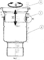
- fig. 1 represents the general view of the drain with the connecting ring
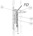
- fig. 2 is the detail of the connecting ring with inserted O-ring
- fig. 3 shows the detail of the connecting ring without a sealing ring
- fig. 4 shows the detail of the "D-D" opening in the connecting ring
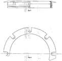
- fig. 5 is the general view of the half of the connecting ring in partial section, indicating the opening in the collar on one side
- fig. 6 is the general view of the half of the ring from above.
- the connecting ring 1 of the floor drain is mounted between the drain body 2 and the drainage extension 3.
- the elastomer connecting ring 1 is fitted with a sealing collar 1.1, which overlaps the rim of the drain body 2.
- the sealing collar 1.1 there are eight U-shaped openings 1.6 for water drainage.
- On the inside there is a sealing lip 1.3, which fits against the drainage extension 2.
- the connecting ring is fitted with a groove 1.5 where the O-ring 1.2 is inserted.
- the connecting ring 1 works as a drainage ring and water can pass through the drainage groove 1.4 and to the drainpipe-arrow FO.
- the connecting ring 1 can be made of rubber, or other suitable material.
- the positioning of the drainage extension 3 in the drain body 2 using the connecting ring is very easy.
- the connecting ring 1 is inserted into the drain body 2 as well as the drainage extension 3, which can be rotated in the direction of arrow "R” and moved in the direction of arrow "H” as needed until the required positioning towards the floor is reached.
Landscapes
- Health & Medical Sciences (AREA)
- Life Sciences & Earth Sciences (AREA)
- Engineering & Computer Science (AREA)
- Hydrology & Water Resources (AREA)
- Public Health (AREA)
- Water Supply & Treatment (AREA)
- Gasket Seals (AREA)
- Sink And Installation For Waste Water (AREA)
- Floor Finish (AREA)
Description
- The invention concerns the connecting ring for floor drains designed for both indoor and outdoor areas where water needs to be removed from the floor. The drain is connected to a grate extension, or a gutter, equipped with a suitable rim for the particular type of the final floor.
- The floor drain bodies are placed in concrete floors, or ceiling structures. A watertight sealing is usually attached to the flange of the drain body. The drain body is equipped with a grate extension, or a floor gutter with grating, designed to remove water from the surface. The connection between the drain body and the extension, or the gutter, is currently performed using a watertight, sealing O-ring. If water needs to be drained from the surface of the watertight sealing, this connection is performed using a drainage ring. A disadvantage of the O-ring connection is difficult installation and height adjustment of the extension with respect to the drain body and the final floor level. Further, it is difficult to check whether the O-ring is positioned correctly. Another disadvantage is the necessity to select a single-purpose ring, i.e. either the O-ring or the drainage ring.
-
EP 1 329 562 A2 -
DE 94 12 393 U1 describes a drainage device for a ground floor or a ceiling. The drainage comprises a drainage body and an attachment piece which is attached to the top of the drainage body. A coupling flange is located at the upper end of the drainage body. A holding ring of the attachment piece rests on this upper end of the drainage body. -
DE 90 03 409 U1 describes a drainage for draining wet rooms. Such drainage devices comprise a drainage body which can be set into the raw ceiling and an attachment piece which can be height-adjusted continuously and which can be set into the drainage body. -
DE 87 15 924 U1 describes another drainage for draining streets and bridges which is height-adjustable. -
DE 18 15 604 A1 describes a drainage body which is height-adjustable. - The above mentioned disadvantages can be eliminated by the method according to
claim 1 and the kit according to claim 5, in particular by the connecting ring for floor drains, mounted between the drain body and the drain extension, following the invention based on the fact that the connecting ring made of flexible material is fitted with a sealing collar in its upper part on the outside. The collar has at least one opening to allow water to pass through. On the inside, the sealing ring is fitted with a sealing lip, and in the bottom part it is equipped with a groove for the O-ring. At the opening, between the outer side of the ring and the inner side of the drain body, there is a drainage groove. The sealing collar of the connecting ring overlaps the rim of the drain body. The flexible material of the connecting ring can be an elastomer, or rubber. - The main advantage of the connecting ring according to the technical design is its universal usage, consisting in the fact that only one type of ring can be used, either with or without a sealing O-ring mounted in the drainage groove, and as compared to the currently used classic O-rings, it enables simple and precise positioning of the drainage extension or gutter in the drain body as well as height adjustment of the drainage extension or gutter depending on the level of the final floor.
- The connecting ring according to the new design is shown in the attached drawings, where
fig. 1 represents the general view of the drain with the connecting ring,fig. 2 is the detail of the connecting ring with inserted O-ring,fig. 3 shows the detail of the connecting ring without a sealing ring,fig. 4 shows the detail of the "D-D" opening in the connecting ring,fig. 5 is the general view of the half of the connecting ring in partial section, indicating the opening in the collar on one side,fig. 6 is the general view of the half of the ring from above. - The connecting
ring 1 of the floor drain is mounted between thedrain body 2 and thedrainage extension 3. In its upper part on the outside, theelastomer connecting ring 1 is fitted with a sealing collar 1.1, which overlaps the rim of thedrain body 2. In the sealing collar 1.1 there are eight U-shaped openings 1.6 for water drainage. On the inside there is a sealing lip 1.3, which fits against thedrainage extension 2. In its bottom part, the connecting ring is fitted with a groove 1.5 where the O-ring 1.2 is inserted. At the openings 1.6 between the outer side of thering 1 and the inner side of thedrain body 2 there are longitudinal pass-through drainage grooves 1.4 for the passage of water removed from the surface. If there is an O-ring 1.2 placed in the groove 1.5, water does not pass through, as shown by the FC arrow. Otherwise, the connectingring 1 works as a drainage ring and water can pass through the drainage groove 1.4 and to the drainpipe-arrow FO. Alternatively, the connectingring 1 can be made of rubber, or other suitable material. - The positioning of the
drainage extension 3 in thedrain body 2 using the connecting ring is very easy. The connectingring 1 is inserted into thedrain body 2 as well as thedrainage extension 3, which can be rotated in the direction of arrow "R" and moved in the direction of arrow "H" as needed until the required positioning towards the floor is reached.
Claims (7)
- Method of mounting a floor drain comprising a drain body (2), a drain extension (3) and a connecting ring (1),
wherein the drain extension (3) is connected with the drain body (2) such that the drain extension (3) is movable in relation to the drain body (2) such that the height of the floor drain can be adjusted,
wherein the connecting ring (1) made of flexible material is in its upper part on the outside fitted with a sealing collar (1.1) with at least one opening (1.6) to allow water to pass through, on the inside the connecting ring (1) is fitted with a sealing lip (1.3), and in the bottom part it is equipped with a groove (1.5) for an O-ring (1.2) for sealing a drainage groove (1.4),
and wherein the connecting ring (1) is mounted between the drain body (2) and the drain extension (3) such that the drainage groove (1.4) of the connecting ring (1) at the opening (1.6) is disposed between the outer side of the connecting ring (1) and the inner side of the drain body (2), wherein
either an O-ring (1.2) is disposed between the connecting ring (1) and the drain body (2) to seal the drainage groove (1.4), or
no O-Ring (1.2) is disposed between the connecting ring (1) and the drain body (2) such that water can drain past the opening (1.6) and via the drainage groove (1.4) into the drain body (2). - Method according to claim 1, characterized in that the connecting ring (1) is mounted such that the sealing collar (1.1) of the connecting ring (1) overlaps the rim of the drain body (2).
- Method according to claim 1 or 2, characterized in that the flexible material of the connecting ring (1) is elastomer.
- Method according to claim 1 or 2, characterized in that the flexible material of the connecting ring (1) is rubber.
- Kit comprising a floor drain and an O-ring, wherein the floor drain comprises a drain body (2), a drain extension (3) and a connecting ring (1) for floor drains,
wherein the drain extension (3) in use is movable in relation to the drain body (2) such that the height of the floor drain can be adjusted,
wherein in use the connecting ring (1) is mounted between the drain body (2) and the drain extension (3),
wherein the connecting ring (1) made of flexible material is in its upper part on the outside fitted with a sealing collar (1.1) with at least one opening (1.6) to allow water to pass through, wherein the sealing collar (1.1) overlaps a rim of the drain body (2);
characterized in that
the connecting ring (1) is mounted in use such that a drainage groove (1.4) of the connecting ring (1) at the opening (1.6) is disposed between the outer side of the connecting ring (1) and the inner side of the drain body (2), wherein the drainage groove is a longitudinal pass through drainage groove and that
on the inside, the connecting ring (1) is fitted with a sealing lip (1.3), and in the bottom part it is equipped with a groove (1.5) for the O-ring (1.2) for sealing the drainage groove (1.4) such, that no water can pass through the drainage groove (1.4), when the O-ring (1.2) is provided in the groove (1.5),
and wherein when no O-ring is provided in the groove (1.5), water can drain past the opening (1.6) and via the drainage groove (1.4) into the drain body (2). - Kit according to claim 6, characterized in that the flexible material of the connecting ring (1) is elastomer.
- Kit according to claim 6, characterized in that the flexible material of the connecting ring (1) is rubber.
Priority Applications (1)
| Application Number | Priority Date | Filing Date | Title |
|---|---|---|---|
| PL11718240T PL2536889T3 (en) | 2010-02-15 | 2011-02-14 | Height-adjustable floor drain with coupling ring provided with channel for seepage water |
Applications Claiming Priority (2)
| Application Number | Priority Date | Filing Date | Title |
|---|---|---|---|
| CZ2010112 | 2010-02-15 | ||
| PCT/CZ2011/000016 WO2011098055A1 (en) | 2010-02-15 | 2011-02-14 | Height-adjustable floor drain with coupling ring provided with channel for seepage water |
Publications (2)
| Publication Number | Publication Date |
|---|---|
| EP2536889A1 EP2536889A1 (en) | 2012-12-26 |
| EP2536889B1 true EP2536889B1 (en) | 2016-12-21 |
Family
ID=44170443
Family Applications (1)
| Application Number | Title | Priority Date | Filing Date |
|---|---|---|---|
| EP11718240.2A Active EP2536889B1 (en) | 2010-02-15 | 2011-02-14 | Height-adjustable floor drain with coupling ring provided with channel for seepage water |
Country Status (7)
| Country | Link |
|---|---|
| EP (1) | EP2536889B1 (en) |
| DK (1) | DK2536889T3 (en) |
| HU (1) | HUE032845T2 (en) |
| LT (1) | LT2536889T (en) |
| PL (1) | PL2536889T3 (en) |
| RU (1) | RU2546857C2 (en) |
| WO (1) | WO2011098055A1 (en) |
Families Citing this family (2)
| Publication number | Priority date | Publication date | Assignee | Title |
|---|---|---|---|---|
| CN106158528B (en) * | 2015-04-28 | 2018-10-19 | 上海电科电器科技有限公司 | The melting welding interrupter of the operating mechanism of breaker |
| CN116695856A (en) * | 2023-07-25 | 2023-09-05 | 娲普智装(秦皇岛)科技开发有限公司 | Assembled floor drain |
Family Cites Families (6)
| Publication number | Priority date | Publication date | Assignee | Title |
|---|---|---|---|---|
| DE1815604C3 (en) * | 1968-12-19 | 1978-11-16 | Josam Manufacturing Co., Michigan City, Ind. (V.St.A.) | Ceiling drain |
| DE8715924U1 (en) * | 1987-12-02 | 1988-01-28 | Eichelmann, Horst, Dipl.-Ing., 6209 Aarbergen | Drainage for road and bridge drainage |
| DE9003409U1 (en) * | 1990-03-23 | 1990-05-31 | Passavant-Werke AG, 6209 Aarbergen | Ceiling, floor or bathroom drain |
| DE9412393U1 (en) * | 1994-08-02 | 1994-11-03 | Passavant-Werke Ag, 65326 Aarbergen | Floor or ceiling drain |
| DE10201345B4 (en) * | 2002-01-16 | 2016-07-28 | Dallmer Gmbh & Co. Kg | Drainage unit for installation in the floor of a room |
| FR2862676B1 (en) * | 2003-11-21 | 2006-01-20 | Saint Gobain Pont A Mousson | LIQUID EXHAUST DEVICE AND CORRESPONDING LIQUID GUIDE DEVICE |
-
2011
- 2011-02-14 LT LTEP11718240.2T patent/LT2536889T/en unknown
- 2011-02-14 RU RU2012139314/13A patent/RU2546857C2/en not_active IP Right Cessation
- 2011-02-14 WO PCT/CZ2011/000016 patent/WO2011098055A1/en not_active Ceased
- 2011-02-14 DK DK11718240.2T patent/DK2536889T3/en active
- 2011-02-14 HU HUE11718240A patent/HUE032845T2/en unknown
- 2011-02-14 EP EP11718240.2A patent/EP2536889B1/en active Active
- 2011-02-14 PL PL11718240T patent/PL2536889T3/en unknown
Also Published As
| Publication number | Publication date |
|---|---|
| LT2536889T (en) | 2017-02-10 |
| PL2536889T3 (en) | 2017-06-30 |
| RU2546857C2 (en) | 2015-04-10 |
| EP2536889A1 (en) | 2012-12-26 |
| WO2011098055A1 (en) | 2011-08-18 |
| DK2536889T3 (en) | 2017-04-03 |
| RU2012139314A (en) | 2014-03-27 |
| HUE032845T2 (en) | 2017-11-28 |
Similar Documents
| Publication | Publication Date | Title |
|---|---|---|
| US11208795B2 (en) | Floor drain for draining water from a walk-in floor into a sewage pipe | |
| CN210737930U (en) | Roof drainer and adjustable roof drainage device | |
| CA2839144C (en) | Drain box assembly for a convertible splash pad/ice rink structure | |
| EP2252743B1 (en) | Siphon construction | |
| DK2536889T3 (en) | Height adjustable floor drain with coupling ring fitted with drainage channel | |
| US6202700B1 (en) | Self-flushing pipe | |
| JP5166851B2 (en) | Rainwater storage device, foundation joint and house with rainwater storage device | |
| EP1141495B1 (en) | Base of a gully | |
| HU226388B1 (en) | Shower tray | |
| JP5437138B2 (en) | Ground subsidence piping structure and ground subsidence piping method | |
| KR200492266Y1 (en) | A drain pipe for sewage | |
| KR200436876Y1 (en) | Noise prevention drain pipe | |
| KR101826619B1 (en) | Non-buoyant sump haning function of preventing leak | |
| JP3929597B2 (en) | Connecting device for temporary drain hose for roof drain | |
| EP2886730A1 (en) | Linear floor drainage | |
| JP4322078B2 (en) | Inflow shut-off device for drain cap | |
| JP4340583B2 (en) | Repair cover device for existing public fence | |
| KR20100010135A (en) | Road drainer with branch pipe connection member for sewage pipe | |
| AU651527B2 (en) | A plumbing fitting | |
| KR20100112941A (en) | Non-noise type construction process of waterway cover | |
| JP2009150155A (en) | Drain mounting structure | |
| EP2365142B1 (en) | Siphon with double mounting | |
| CN202227460U (en) | Floor embedded part sleeve capable of fastening water pipe | |
| JP2018053640A (en) | Drain pipe member | |
| ES2958962A1 (en) | Adapter for pool skimmer in rehabilitation works |
Legal Events
| Date | Code | Title | Description |
|---|---|---|---|
| PUAI | Public reference made under article 153(3) epc to a published international application that has entered the european phase |
Free format text: ORIGINAL CODE: 0009012 |
|
| 17P | Request for examination filed |
Effective date: 20120912 |
|
| AK | Designated contracting states |
Kind code of ref document: A1 Designated state(s): AL AT BE BG CH CY CZ DE DK EE ES FI FR GB GR HR HU IE IS IT LI LT LU LV MC MK MT NL NO PL PT RO RS SE SI SK SM TR |
|
| DAX | Request for extension of the european patent (deleted) | ||
| 17Q | First examination report despatched |
Effective date: 20140829 |
|
| GRAP | Despatch of communication of intention to grant a patent |
Free format text: ORIGINAL CODE: EPIDOSNIGR1 |
|
| INTG | Intention to grant announced |
Effective date: 20160630 |
|
| GRAS | Grant fee paid |
Free format text: ORIGINAL CODE: EPIDOSNIGR3 |
|
| GRAA | (expected) grant |
Free format text: ORIGINAL CODE: 0009210 |
|
| AK | Designated contracting states |
Kind code of ref document: B1 Designated state(s): AL AT BE BG CH CY CZ DE DK EE ES FI FR GB GR HR HU IE IS IT LI LT LU LV MC MK MT NL NO PL PT RO RS SE SI SK SM TR |
|
| REG | Reference to a national code |
Ref country code: GB Ref legal event code: FG4D |
|
| REG | Reference to a national code |
Ref country code: CH Ref legal event code: EP |
|
| REG | Reference to a national code |
Ref country code: IE Ref legal event code: FG4D |
|
| REG | Reference to a national code |
Ref country code: AT Ref legal event code: REF Ref document number: 855638 Country of ref document: AT Kind code of ref document: T Effective date: 20170115 |
|
| REG | Reference to a national code |
Ref country code: DE Ref legal event code: R096 Ref document number: 602011033598 Country of ref document: DE |
|
| REG | Reference to a national code |
Ref country code: FR Ref legal event code: PLFP Year of fee payment: 7 |
|
| REG | Reference to a national code |
Ref country code: RO Ref legal event code: EPE |
|
| PG25 | Lapsed in a contracting state [announced via postgrant information from national office to epo] |
Ref country code: LV Free format text: LAPSE BECAUSE OF FAILURE TO SUBMIT A TRANSLATION OF THE DESCRIPTION OR TO PAY THE FEE WITHIN THE PRESCRIBED TIME-LIMIT Effective date: 20161221 |
|
| REG | Reference to a national code |
Ref country code: SE Ref legal event code: TRGR |
|
| REG | Reference to a national code |
Ref country code: DK Ref legal event code: T3 Effective date: 20170328 |
|
| REG | Reference to a national code |
Ref country code: NL Ref legal event code: MP Effective date: 20161221 |
|
| PG25 | Lapsed in a contracting state [announced via postgrant information from national office to epo] |
Ref country code: GR Free format text: LAPSE BECAUSE OF FAILURE TO SUBMIT A TRANSLATION OF THE DESCRIPTION OR TO PAY THE FEE WITHIN THE PRESCRIBED TIME-LIMIT Effective date: 20170322 |
|
| REG | Reference to a national code |
Ref country code: NO Ref legal event code: T2 Effective date: 20161221 |
|
| PG25 | Lapsed in a contracting state [announced via postgrant information from national office to epo] |
Ref country code: RS Free format text: LAPSE BECAUSE OF FAILURE TO SUBMIT A TRANSLATION OF THE DESCRIPTION OR TO PAY THE FEE WITHIN THE PRESCRIBED TIME-LIMIT Effective date: 20161221 Ref country code: HR Free format text: LAPSE BECAUSE OF FAILURE TO SUBMIT A TRANSLATION OF THE DESCRIPTION OR TO PAY THE FEE WITHIN THE PRESCRIBED TIME-LIMIT Effective date: 20161221 |
|
| PG25 | Lapsed in a contracting state [announced via postgrant information from national office to epo] |
Ref country code: NL Free format text: LAPSE BECAUSE OF FAILURE TO SUBMIT A TRANSLATION OF THE DESCRIPTION OR TO PAY THE FEE WITHIN THE PRESCRIBED TIME-LIMIT Effective date: 20161221 |
|
| PG25 | Lapsed in a contracting state [announced via postgrant information from national office to epo] |
Ref country code: IS Free format text: LAPSE BECAUSE OF FAILURE TO SUBMIT A TRANSLATION OF THE DESCRIPTION OR TO PAY THE FEE WITHIN THE PRESCRIBED TIME-LIMIT Effective date: 20170421 Ref country code: SK Free format text: LAPSE BECAUSE OF FAILURE TO SUBMIT A TRANSLATION OF THE DESCRIPTION OR TO PAY THE FEE WITHIN THE PRESCRIBED TIME-LIMIT Effective date: 20161221 Ref country code: EE Free format text: LAPSE BECAUSE OF FAILURE TO SUBMIT A TRANSLATION OF THE DESCRIPTION OR TO PAY THE FEE WITHIN THE PRESCRIBED TIME-LIMIT Effective date: 20161221 |
|
| PG25 | Lapsed in a contracting state [announced via postgrant information from national office to epo] |
Ref country code: IT Free format text: LAPSE BECAUSE OF FAILURE TO SUBMIT A TRANSLATION OF THE DESCRIPTION OR TO PAY THE FEE WITHIN THE PRESCRIBED TIME-LIMIT Effective date: 20161221 Ref country code: BG Free format text: LAPSE BECAUSE OF FAILURE TO SUBMIT A TRANSLATION OF THE DESCRIPTION OR TO PAY THE FEE WITHIN THE PRESCRIBED TIME-LIMIT Effective date: 20170321 Ref country code: ES Free format text: LAPSE BECAUSE OF FAILURE TO SUBMIT A TRANSLATION OF THE DESCRIPTION OR TO PAY THE FEE WITHIN THE PRESCRIBED TIME-LIMIT Effective date: 20161221 Ref country code: PT Free format text: LAPSE BECAUSE OF FAILURE TO SUBMIT A TRANSLATION OF THE DESCRIPTION OR TO PAY THE FEE WITHIN THE PRESCRIBED TIME-LIMIT Effective date: 20170421 Ref country code: SM Free format text: LAPSE BECAUSE OF FAILURE TO SUBMIT A TRANSLATION OF THE DESCRIPTION OR TO PAY THE FEE WITHIN THE PRESCRIBED TIME-LIMIT Effective date: 20161221 |
|
| REG | Reference to a national code |
Ref country code: DE Ref legal event code: R097 Ref document number: 602011033598 Country of ref document: DE |
|
| PG25 | Lapsed in a contracting state [announced via postgrant information from national office to epo] |
Ref country code: MC Free format text: LAPSE BECAUSE OF FAILURE TO SUBMIT A TRANSLATION OF THE DESCRIPTION OR TO PAY THE FEE WITHIN THE PRESCRIBED TIME-LIMIT Effective date: 20161221 |
|
| REG | Reference to a national code |
Ref country code: CH Ref legal event code: PL |
|
| PLBE | No opposition filed within time limit |
Free format text: ORIGINAL CODE: 0009261 |
|
| STAA | Information on the status of an ep patent application or granted ep patent |
Free format text: STATUS: NO OPPOSITION FILED WITHIN TIME LIMIT |
|
| PG25 | Lapsed in a contracting state [announced via postgrant information from national office to epo] |
Ref country code: CH Free format text: LAPSE BECAUSE OF NON-PAYMENT OF DUE FEES Effective date: 20170228 Ref country code: LI Free format text: LAPSE BECAUSE OF NON-PAYMENT OF DUE FEES Effective date: 20170228 |
|
| REG | Reference to a national code |
Ref country code: HU Ref legal event code: AG4A Ref document number: E032845 Country of ref document: HU |
|
| 26N | No opposition filed |
Effective date: 20170922 |
|
| REG | Reference to a national code |
Ref country code: IE Ref legal event code: MM4A |
|
| PG25 | Lapsed in a contracting state [announced via postgrant information from national office to epo] |
Ref country code: LU Free format text: LAPSE BECAUSE OF NON-PAYMENT OF DUE FEES Effective date: 20170214 |
|
| REG | Reference to a national code |
Ref country code: FR Ref legal event code: PLFP Year of fee payment: 8 |
|
| PG25 | Lapsed in a contracting state [announced via postgrant information from national office to epo] |
Ref country code: SI Free format text: LAPSE BECAUSE OF FAILURE TO SUBMIT A TRANSLATION OF THE DESCRIPTION OR TO PAY THE FEE WITHIN THE PRESCRIBED TIME-LIMIT Effective date: 20161221 Ref country code: IE Free format text: LAPSE BECAUSE OF NON-PAYMENT OF DUE FEES Effective date: 20170214 |
|
| PG25 | Lapsed in a contracting state [announced via postgrant information from national office to epo] |
Ref country code: MT Free format text: LAPSE BECAUSE OF NON-PAYMENT OF DUE FEES Effective date: 20170214 |
|
| PG25 | Lapsed in a contracting state [announced via postgrant information from national office to epo] |
Ref country code: CY Free format text: LAPSE BECAUSE OF NON-PAYMENT OF DUE FEES Effective date: 20161221 |
|
| PG25 | Lapsed in a contracting state [announced via postgrant information from national office to epo] |
Ref country code: MK Free format text: LAPSE BECAUSE OF FAILURE TO SUBMIT A TRANSLATION OF THE DESCRIPTION OR TO PAY THE FEE WITHIN THE PRESCRIBED TIME-LIMIT Effective date: 20161221 |
|
| REG | Reference to a national code |
Ref country code: AT Ref legal event code: UEP Ref document number: 855638 Country of ref document: AT Kind code of ref document: T Effective date: 20161221 |
|
| PG25 | Lapsed in a contracting state [announced via postgrant information from national office to epo] |
Ref country code: TR Free format text: LAPSE BECAUSE OF FAILURE TO SUBMIT A TRANSLATION OF THE DESCRIPTION OR TO PAY THE FEE WITHIN THE PRESCRIBED TIME-LIMIT Effective date: 20161221 |
|
| PGFP | Annual fee paid to national office [announced via postgrant information from national office to epo] |
Ref country code: LT Payment date: 20200204 Year of fee payment: 10 |
|
| PG25 | Lapsed in a contracting state [announced via postgrant information from national office to epo] |
Ref country code: AL Free format text: LAPSE BECAUSE OF FAILURE TO SUBMIT A TRANSLATION OF THE DESCRIPTION OR TO PAY THE FEE WITHIN THE PRESCRIBED TIME-LIMIT Effective date: 20161221 |
|
| REG | Reference to a national code |
Ref country code: LT Ref legal event code: MM4D Effective date: 20210214 |
|
| PG25 | Lapsed in a contracting state [announced via postgrant information from national office to epo] |
Ref country code: LT Free format text: LAPSE BECAUSE OF NON-PAYMENT OF DUE FEES Effective date: 20210214 |
|
| P01 | Opt-out of the competence of the unified patent court (upc) registered |
Effective date: 20230629 |
|
| PGFP | Annual fee paid to national office [announced via postgrant information from national office to epo] |
Ref country code: HU Payment date: 20260212 Year of fee payment: 16 |
|
| PGFP | Annual fee paid to national office [announced via postgrant information from national office to epo] |
Ref country code: SE Payment date: 20260218 Year of fee payment: 16 |
|
| PGFP | Annual fee paid to national office [announced via postgrant information from national office to epo] |
Ref country code: GB Payment date: 20260219 Year of fee payment: 16 |
|
| PGFP | Annual fee paid to national office [announced via postgrant information from national office to epo] |
Ref country code: NO Payment date: 20260217 Year of fee payment: 16 Ref country code: DK Payment date: 20260217 Year of fee payment: 16 Ref country code: DE Payment date: 20260217 Year of fee payment: 16 |
|
| PGFP | Annual fee paid to national office [announced via postgrant information from national office to epo] |
Ref country code: AT Payment date: 20260216 Year of fee payment: 16 |
|
| PGFP | Annual fee paid to national office [announced via postgrant information from national office to epo] |
Ref country code: FI Payment date: 20260217 Year of fee payment: 16 Ref country code: RO Payment date: 20260210 Year of fee payment: 16 Ref country code: BE Payment date: 20260218 Year of fee payment: 16 |
|
| PGFP | Annual fee paid to national office [announced via postgrant information from national office to epo] |
Ref country code: FR Payment date: 20260219 Year of fee payment: 16 |
|
| PGFP | Annual fee paid to national office [announced via postgrant information from national office to epo] |
Ref country code: CZ Payment date: 20260130 Year of fee payment: 16 |
|
| PGFP | Annual fee paid to national office [announced via postgrant information from national office to epo] |
Ref country code: PL Payment date: 20260209 Year of fee payment: 16 |