EP2536811B1 - Vergasungseinrichtung und vergasungsverfahren - Google Patents
Vergasungseinrichtung und vergasungsverfahren Download PDFInfo
- Publication number
- EP2536811B1 EP2536811B1 EP10705847.1A EP10705847A EP2536811B1 EP 2536811 B1 EP2536811 B1 EP 2536811B1 EP 10705847 A EP10705847 A EP 10705847A EP 2536811 B1 EP2536811 B1 EP 2536811B1
- Authority
- EP
- European Patent Office
- Prior art keywords
- gasification
- zone
- oxidation
- air
- solid
- Prior art date
- Legal status (The legal status is an assumption and is not a legal conclusion. Google has not performed a legal analysis and makes no representation as to the accuracy of the status listed.)
- Not-in-force
Links
- 238000002309 gasification Methods 0.000 title claims description 235
- 238000000034 method Methods 0.000 title claims description 37
- 230000003647 oxidation Effects 0.000 claims description 90
- 238000007254 oxidation reaction Methods 0.000 claims description 90
- 239000007787 solid Substances 0.000 claims description 55
- 239000007789 gas Substances 0.000 claims description 54
- 230000033001 locomotion Effects 0.000 claims description 36
- 238000000197 pyrolysis Methods 0.000 claims description 19
- 238000011049 filling Methods 0.000 claims description 9
- QVGXLLKOCUKJST-UHFFFAOYSA-N atomic oxygen Chemical compound [O] QVGXLLKOCUKJST-UHFFFAOYSA-N 0.000 claims description 7
- 239000001301 oxygen Substances 0.000 claims description 7
- 229910052760 oxygen Inorganic materials 0.000 claims description 7
- 239000002737 fuel gas Substances 0.000 claims description 6
- 238000002156 mixing Methods 0.000 claims description 6
- 238000012546 transfer Methods 0.000 claims description 6
- 230000000694 effects Effects 0.000 claims description 5
- 230000036961 partial effect Effects 0.000 claims description 4
- 230000001419 dependent effect Effects 0.000 claims description 3
- 238000013461 design Methods 0.000 claims description 2
- 238000012216 screening Methods 0.000 claims description 2
- 238000003776 cleavage reaction Methods 0.000 claims 1
- 230000007017 scission Effects 0.000 claims 1
- 239000003570 air Substances 0.000 description 122
- 230000005484 gravity Effects 0.000 description 8
- 238000012549 training Methods 0.000 description 7
- 239000000571 coke Substances 0.000 description 6
- 239000000203 mixture Substances 0.000 description 6
- 238000011161 development Methods 0.000 description 4
- 238000005192 partition Methods 0.000 description 4
- 239000012080 ambient air Substances 0.000 description 3
- 239000002956 ash Substances 0.000 description 3
- 230000015572 biosynthetic process Effects 0.000 description 3
- 239000000470 constituent Substances 0.000 description 3
- 238000001914 filtration Methods 0.000 description 3
- 238000012423 maintenance Methods 0.000 description 3
- 230000002093 peripheral effect Effects 0.000 description 3
- 230000001105 regulatory effect Effects 0.000 description 3
- 239000000523 sample Substances 0.000 description 3
- 238000007872 degassing Methods 0.000 description 2
- 238000001514 detection method Methods 0.000 description 2
- JEIPFZHSYJVQDO-UHFFFAOYSA-N iron(III) oxide Inorganic materials O=[Fe]O[Fe]=O JEIPFZHSYJVQDO-UHFFFAOYSA-N 0.000 description 2
- 230000000670 limiting effect Effects 0.000 description 2
- 239000000463 material Substances 0.000 description 2
- 239000007800 oxidant agent Substances 0.000 description 2
- 238000004886 process control Methods 0.000 description 2
- 230000002829 reductive effect Effects 0.000 description 2
- 238000004227 thermal cracking Methods 0.000 description 2
- 239000002028 Biomass Substances 0.000 description 1
- OKTJSMMVPCPJKN-UHFFFAOYSA-N Carbon Chemical group [C] OKTJSMMVPCPJKN-UHFFFAOYSA-N 0.000 description 1
- 235000002918 Fraxinus excelsior Nutrition 0.000 description 1
- 238000009825 accumulation Methods 0.000 description 1
- 239000000443 aerosol Substances 0.000 description 1
- 239000002551 biofuel Substances 0.000 description 1
- 230000005540 biological transmission Effects 0.000 description 1
- 239000003575 carbonaceous material Substances 0.000 description 1
- 239000003054 catalyst Substances 0.000 description 1
- 238000004140 cleaning Methods 0.000 description 1
- 238000002485 combustion reaction Methods 0.000 description 1
- 238000010276 construction Methods 0.000 description 1
- 238000011109 contamination Methods 0.000 description 1
- 230000001276 controlling effect Effects 0.000 description 1
- 230000008878 coupling Effects 0.000 description 1
- 238000010168 coupling process Methods 0.000 description 1
- 238000005859 coupling reaction Methods 0.000 description 1
- 238000005520 cutting process Methods 0.000 description 1
- 230000008021 deposition Effects 0.000 description 1
- 239000007788 liquid Substances 0.000 description 1
- 238000004519 manufacturing process Methods 0.000 description 1
- 238000012544 monitoring process Methods 0.000 description 1
- 230000001590 oxidative effect Effects 0.000 description 1
- 239000002245 particle Substances 0.000 description 1
- 239000013618 particulate matter Substances 0.000 description 1
- 230000035515 penetration Effects 0.000 description 1
- 239000000843 powder Substances 0.000 description 1
- 239000002244 precipitate Substances 0.000 description 1
- 238000001556 precipitation Methods 0.000 description 1
- 230000000284 resting effect Effects 0.000 description 1
- 230000002441 reversible effect Effects 0.000 description 1
- 238000000926 separation method Methods 0.000 description 1
- 238000000638 solvent extraction Methods 0.000 description 1
- 239000000126 substance Substances 0.000 description 1
- 238000005979 thermal decomposition reaction Methods 0.000 description 1
- XLYOFNOQVPJJNP-UHFFFAOYSA-N water Substances O XLYOFNOQVPJJNP-UHFFFAOYSA-N 0.000 description 1
- 239000002023 wood Substances 0.000 description 1
Images

Classifications
-
- C—CHEMISTRY; METALLURGY
- C10—PETROLEUM, GAS OR COKE INDUSTRIES; TECHNICAL GASES CONTAINING CARBON MONOXIDE; FUELS; LUBRICANTS; PEAT
- C10J—PRODUCTION OF PRODUCER GAS, WATER-GAS, SYNTHESIS GAS FROM SOLID CARBONACEOUS MATERIAL, OR MIXTURES CONTAINING THESE GASES; CARBURETTING AIR OR OTHER GASES
- C10J3/00—Production of combustible gases containing carbon monoxide from solid carbonaceous fuels
- C10J3/72—Other features
- C10J3/721—Multistage gasification, e.g. plural parallel or serial gasification stages
-
- C—CHEMISTRY; METALLURGY
- C10—PETROLEUM, GAS OR COKE INDUSTRIES; TECHNICAL GASES CONTAINING CARBON MONOXIDE; FUELS; LUBRICANTS; PEAT
- C10J—PRODUCTION OF PRODUCER GAS, WATER-GAS, SYNTHESIS GAS FROM SOLID CARBONACEOUS MATERIAL, OR MIXTURES CONTAINING THESE GASES; CARBURETTING AIR OR OTHER GASES
- C10J3/00—Production of combustible gases containing carbon monoxide from solid carbonaceous fuels
- C10J3/02—Fixed-bed gasification of lump fuel
- C10J3/06—Continuous processes
-
- C—CHEMISTRY; METALLURGY
- C10—PETROLEUM, GAS OR COKE INDUSTRIES; TECHNICAL GASES CONTAINING CARBON MONOXIDE; FUELS; LUBRICANTS; PEAT
- C10J—PRODUCTION OF PRODUCER GAS, WATER-GAS, SYNTHESIS GAS FROM SOLID CARBONACEOUS MATERIAL, OR MIXTURES CONTAINING THESE GASES; CARBURETTING AIR OR OTHER GASES
- C10J3/00—Production of combustible gases containing carbon monoxide from solid carbonaceous fuels
- C10J3/02—Fixed-bed gasification of lump fuel
- C10J3/20—Apparatus; Plants
- C10J3/22—Arrangements or dispositions of valves or flues
- C10J3/24—Arrangements or dispositions of valves or flues to permit flow of gases or vapours other than upwardly through the fuel bed
- C10J3/26—Arrangements or dispositions of valves or flues to permit flow of gases or vapours other than upwardly through the fuel bed downwardly
-
- C—CHEMISTRY; METALLURGY
- C10—PETROLEUM, GAS OR COKE INDUSTRIES; TECHNICAL GASES CONTAINING CARBON MONOXIDE; FUELS; LUBRICANTS; PEAT
- C10J—PRODUCTION OF PRODUCER GAS, WATER-GAS, SYNTHESIS GAS FROM SOLID CARBONACEOUS MATERIAL, OR MIXTURES CONTAINING THESE GASES; CARBURETTING AIR OR OTHER GASES
- C10J3/00—Production of combustible gases containing carbon monoxide from solid carbonaceous fuels
- C10J3/02—Fixed-bed gasification of lump fuel
- C10J3/20—Apparatus; Plants
- C10J3/32—Devices for distributing fuel evenly over the bed or for stirring up the fuel bed
-
- C—CHEMISTRY; METALLURGY
- C10—PETROLEUM, GAS OR COKE INDUSTRIES; TECHNICAL GASES CONTAINING CARBON MONOXIDE; FUELS; LUBRICANTS; PEAT
- C10J—PRODUCTION OF PRODUCER GAS, WATER-GAS, SYNTHESIS GAS FROM SOLID CARBONACEOUS MATERIAL, OR MIXTURES CONTAINING THESE GASES; CARBURETTING AIR OR OTHER GASES
- C10J3/00—Production of combustible gases containing carbon monoxide from solid carbonaceous fuels
- C10J3/02—Fixed-bed gasification of lump fuel
- C10J3/20—Apparatus; Plants
- C10J3/34—Grates; Mechanical ash-removing devices
- C10J3/40—Movable grates
-
- C—CHEMISTRY; METALLURGY
- C10—PETROLEUM, GAS OR COKE INDUSTRIES; TECHNICAL GASES CONTAINING CARBON MONOXIDE; FUELS; LUBRICANTS; PEAT
- C10J—PRODUCTION OF PRODUCER GAS, WATER-GAS, SYNTHESIS GAS FROM SOLID CARBONACEOUS MATERIAL, OR MIXTURES CONTAINING THESE GASES; CARBURETTING AIR OR OTHER GASES
- C10J3/00—Production of combustible gases containing carbon monoxide from solid carbonaceous fuels
- C10J3/58—Production of combustible gases containing carbon monoxide from solid carbonaceous fuels combined with pre-distillation of the fuel
- C10J3/60—Processes
- C10J3/64—Processes with decomposition of the distillation products
-
- C—CHEMISTRY; METALLURGY
- C10—PETROLEUM, GAS OR COKE INDUSTRIES; TECHNICAL GASES CONTAINING CARBON MONOXIDE; FUELS; LUBRICANTS; PEAT
- C10J—PRODUCTION OF PRODUCER GAS, WATER-GAS, SYNTHESIS GAS FROM SOLID CARBONACEOUS MATERIAL, OR MIXTURES CONTAINING THESE GASES; CARBURETTING AIR OR OTHER GASES
- C10J2200/00—Details of gasification apparatus
- C10J2200/15—Details of feeding means
- C10J2200/152—Nozzles or lances for introducing gas, liquids or suspensions
-
- C—CHEMISTRY; METALLURGY
- C10—PETROLEUM, GAS OR COKE INDUSTRIES; TECHNICAL GASES CONTAINING CARBON MONOXIDE; FUELS; LUBRICANTS; PEAT
- C10J—PRODUCTION OF PRODUCER GAS, WATER-GAS, SYNTHESIS GAS FROM SOLID CARBONACEOUS MATERIAL, OR MIXTURES CONTAINING THESE GASES; CARBURETTING AIR OR OTHER GASES
- C10J2300/00—Details of gasification processes
- C10J2300/09—Details of the feed, e.g. feeding of spent catalyst, inert gas or halogens
- C10J2300/0953—Gasifying agents
- C10J2300/0956—Air or oxygen enriched air
-
- C—CHEMISTRY; METALLURGY
- C10—PETROLEUM, GAS OR COKE INDUSTRIES; TECHNICAL GASES CONTAINING CARBON MONOXIDE; FUELS; LUBRICANTS; PEAT
- C10J—PRODUCTION OF PRODUCER GAS, WATER-GAS, SYNTHESIS GAS FROM SOLID CARBONACEOUS MATERIAL, OR MIXTURES CONTAINING THESE GASES; CARBURETTING AIR OR OTHER GASES
- C10J2300/00—Details of gasification processes
- C10J2300/16—Integration of gasification processes with another plant or parts within the plant
- C10J2300/1603—Integration of gasification processes with another plant or parts within the plant with gas treatment
- C10J2300/1606—Combustion processes
-
- C—CHEMISTRY; METALLURGY
- C10—PETROLEUM, GAS OR COKE INDUSTRIES; TECHNICAL GASES CONTAINING CARBON MONOXIDE; FUELS; LUBRICANTS; PEAT
- C10J—PRODUCTION OF PRODUCER GAS, WATER-GAS, SYNTHESIS GAS FROM SOLID CARBONACEOUS MATERIAL, OR MIXTURES CONTAINING THESE GASES; CARBURETTING AIR OR OTHER GASES
- C10J2300/00—Details of gasification processes
- C10J2300/16—Integration of gasification processes with another plant or parts within the plant
- C10J2300/1603—Integration of gasification processes with another plant or parts within the plant with gas treatment
- C10J2300/1609—Post-reduction, e.g. on a red-white-hot coke or coal bed
-
- C—CHEMISTRY; METALLURGY
- C10—PETROLEUM, GAS OR COKE INDUSTRIES; TECHNICAL GASES CONTAINING CARBON MONOXIDE; FUELS; LUBRICANTS; PEAT
- C10J—PRODUCTION OF PRODUCER GAS, WATER-GAS, SYNTHESIS GAS FROM SOLID CARBONACEOUS MATERIAL, OR MIXTURES CONTAINING THESE GASES; CARBURETTING AIR OR OTHER GASES
- C10J2300/00—Details of gasification processes
- C10J2300/18—Details of the gasification process, e.g. loops, autothermal operation
- C10J2300/1846—Partial oxidation, i.e. injection of air or oxygen only
Definitions
- Another aspect of the invention is a gasification process for producing a flammable gas from a solid.
- Gasification facilities or carburetor or gas generators of the aforementioned type and gasification processes are used to gas solid substances such as organic or inorganic carbonaceous materials, in particular wood, plants or plant residues, especially in pelletized form as completely as possible in a controlled process, to thereby to produce an ignitable, in particular combustible gas.
- this gas thus produced is burned in a process downstream of the gasification to thereby perform work and, for example, operate a power generator.
- EP 1 865 046 A1 are known a gasifier and a gasification process, which in a shaft gasifier in a three-stage process by gasification of the solid, partial oxidation and thermal decomposition of the gas and reduction generates an ignitable gas.
- the disclosure of this patent application is incorporated by reference in its entirety EP 1 865 046 A1 included.
- a disadvantage of the prior art disclosed in this patent application is that gasification often succeeds only incompletely and that the amount of energy lying in the solid is thereby not completely exhausted.
- Another disadvantage of such prior art method or carburetor is that the carburetor tends to contamination during normal operation and thus relatively short maintenance intervals for its regular cleaning are required.
- US 2009/0282738 For example, there is known an apparatus and method for producing biofuel having generally concentric chambers including a combustion chamber and at least one pyrolysis chamber.
- US 2007/0006528 shows a method and apparatus for producing a fuel gas from biomass.
- the apparatus includes a plurality of levels, each level including a plurality of radially extending air supply tubes.
- the air supply pipes are distributed over the circumference.
- Each level is supplied with variable air volumes.
- a gasification zone is provided, which is functionally divided with respect to the temperature control and air supply in at least two, preferably more than two gasification sectors.
- a functional division can be achieved, for example, in that the gasification sectors are not separated from one another by structural elements, but instead a separate air supply is provided for each gasification sector and the gasification sector essentially or at least in a temperature-relevant proportion from the air supply provided to it is supplied with air.
- a total of contiguous and non-constructively divided gasification zone can be provided, which is virtually divided functionally due to the separate air supply in defined gasification sectors.
- the gasification zone may also be divided by partitions such as partitions or the like such that transfer of solid and gas from one gasification sector to another gasification sector is not immediately possible, especially not directly, so that the gasification process in each gasification sector is largely isolated Process takes place.
- the prevailing temperature is detected in each gasification sector.
- a corresponding temperature measuring device which measures, for example, by means of a single temperature measuring instrument in successive measuring cycles, the temperature of the individual gasification sectors or which comprises a plurality of temperature measuring devices and a respective temperature measuring device is associated with a gasification sector.
- the temperature measuring device is signal-wise coupled to a control unit which serves to set the temperature in each gasification sector in an optimal range for the gasification. It is to be understood that the control device can in particular regulate a closed control process in a control loop.
- the control device is in turn signal-technically coupled to an air supply unit which is designed to supply air to each gasification sector.
- each gasification sector can be supplied with an ideal air volume for the conditions prevailing in this gasification sector or, in certain situations, no air can be supplied.
- a gasification sector too low a temperature, ie a temperature below the ideal process temperature in the reverse case, that is, too high a temperature above the ideal process temperature in a gasification sector, to reduce the supply of air to this gasification sector.
- another detection device can also be used, which allows a direct or indirect conclusion on the efficiency of the gasification process in the respective sector, for example an analysis device for determining the composition of the pyrolysis gas or parts thereof.
- the gasification zone in at least two, preferably several sectors, for example, four each over a peripheral portion of 90 ° extending gasification sectors is divided and the gasification based on the prevailing temperature and their regulation or control by air supply in each gasification sector separately is controlled or regulated.
- the gasification sectors may be evenly or non-uniformly distributed around the circumference and be provided with two, three, four, five or more sectors.
- the oxidation zone is, based on its cross-section, at least partially, preferably completely surrounded by the gasification zone. Accordingly, the oxidation zone is arranged centrally within the gasification device by being surrounded by the gasification zone in relation to a cross section through the gasification device at least in a region, but preferably completely. As a result, in particular, an annular gasification zone is formed around the oxidation zone and consequently enables effective heat transfer from the gasification zone into the oxidation zone and vice versa.
- this embodiment can be realized such that the gasification device is designed as a shaft carburetor and the oxidation zone is designed as centrally disposed within the Schachtvergasers oxidation chamber, which is surrounded by an annular gasification zone.
- an air supply tube connected at its first end to the oxidation zone, in particular protruding into the oxidation zone, and connected at its other end to a source of oxygen-containing air.
- This training is executable or independently and without such a divided gasification zone, temperature measuring unit, control unit and / or air supply both in connection with the above-described, divided into several adjacent gasification sectors gasification zone and related temperature measuring unit, control unit and air supply.
- the air supply tube preferably extends from an upper end of the gasification device in the longitudinal direction, in particular along the central axis of the gasification device, downwards in the direction of the oxidation zone.
- the air supply tube is at least partially disposed in a cover tube and an annular space between the air supply tube and the cover tube is formed, which is connected at its first end to the gasification zone and connected at its other end to a source of oxygen-containing air is.
- the gasification zone as described in the prior art, can be supplied with the air required for the gasification from the outside, for example via a plurality of air inlet pipes or nozzles projecting from the outside into the gasification zone.
- this cross-sectional components should also achieve an efficient gasification, which are spaced from the outside of this air supply, it is advantageous to provide a further, in the vicinity of these cross-sectional areas opening air supply. This can be done effectively by the sheath tube.
- the sheath tube may in principle be arranged so that it runs in the interior of the gasification device, in particular, if the gasification device is designed as a shaft carburetor, along and parallel, preferably coaxially to the longitudinal axis of the shaft gasifier. In this way, an introduction of air into a central region of the gasification zone, in particular in that region of the gasification zone which directly adjoins the oxidation zone, is made possible.
- the casing pipe may also be configured to have separate air ducts, in particular the same number as the number of gasification sectors, around the duct between the duct and the air duct To be able to adapt air individually to the needs of the respective gasification sector. This can be achieved for example by radially extending partitions, through which the annulus is divided into several annulus sectors and these annulus sectors are subjected to an individual air mass flow.
- air in particular ambient air can be understood, but this gas or gas mixtures are to be understood, which differ from the composition of the ambient air, especially for example gas mixtures containing an increased proportion of oxygen or Gas mixtures to which are admixed components which act as a catalyst or which contain particular gasification or oxidation-promoting components or components which prevent deposits within the gasification apparatus.
- these proportions may be gaseous fractions.
- the proportions can also be added in liquid form, for example in the form of an aerosol or in solid form, for example in the form of a powder.
- the supplied air can be enriched in certain process situations with water or steam in order to favorably influence the pyrolysis or gasification or oxidation or, as explained below, reduction.
- the oxidation zone is arranged in an oxidation chamber bounded by one or more walls, in particular limited to the gasification zone, and that at least segments of these walls, preferably all walls, are movable with respect to the gasification zone are guided, in particular are guided rotatably.
- this training may be practiced in combination with the previously discussed partitioning of the gasification zone in gasification sectors and the temperature measuring unit and the control unit and / or the air supply means or without this division and units or devices, i. insofar represents an independent training a gasification of the initially described construction.
- the walls at least partially, but in particular to move a total, a relative movement between the stored in the gasification solids and the moving walls is achieved, whereby the structure of adhering to these walls solid layer, for example by precipitation from the pyrolysis gases , can be effectively prevented.
- this build-up of precipitates or deposits can reduce the efficiency of the gasification, on the other hand impair or disturb the above-mentioned functioning of the gasification device.
- the movement can be carried out as a rotational movement, for example about the longitudinal axis of the gasification device, in particular if the gasification device is designed as a shaft gasifier.
- other forms of movement are conceivable, for example translational movements.
- the mode of movement may be a continuous movement in one direction, but in certain applications, reciprocal, that is to say reciprocal, are also involved. reciprocating motion forms with a regular direction of motion reversal advantageous.
- an air supply pipe is provided, be provided in particular that the walls or wall segments are mechanically coupled to the air supply pipe for transmitting a movement, in particular a rotational movement and preferably an actuator is provided, which is coupled to the air supply pipe for introducing the movement, or the rotational movement.
- a movement in particular a rotational movement and preferably an actuator is provided, which is coupled to the air supply pipe for introducing the movement, or the rotational movement.
- an effective and structurally reliable transmission of the movement to the wall or walls is achieved, which define or limit the oxidation zone.
- both a translational movement direction for example in the longitudinal direction of a gasification device designed as a shaft carburetor or a rotational movement, can be provided via the air supply tube, be realized, for example, about the longitudinal axis of a gasification device designed as a shaft carburetor or a motion form composed thereof.
- one or more blade elements are arranged on one or more walls of the oxidation chamber, which extend from the walls into the gasification zone and are designed to move by movement of the wall or of the wall segment to which it is attached are to cause a conveying, crushing or mixing movement in the solid in the gasification zone.
- Such blade elements which may be embodied, for example, in the form of paddles, rods, blades with or without twisting, cause mixing and optionally comminution and / or promotion in the solids region into which they extend when they extend relative to this move.
- the blade elements may be arranged on a plane or staggered with respect to one another, for example along a helical line on the outer surface of the walls delimiting the oxidation zone, and in particular arranged circumferentially about a longitudinal axis of a gasification device designed as a shaft carburetor.
- Such blade elements can contribute to a more homogeneous composition of the solids in the region of the gasification zone both in a translatory, but in particular in a rotating movement of the wall element or the wall / walls to which they are attached and thereby achieve a more efficient gasification.
- a reduction zone which is connected to the oxidation zone for supplying the raw gas formed in the oxidation zone and is designed to reduce the raw gas supplied to it.
- a fuel gas can be generated from the pyrolysis gas processed in the oxidation zone.
- filtering of solid constituents by the coke in the reduction zone can furthermore be achieved.
- other methods for filtering for example by means of filter candles or the like may be provided.
- the gasification apparatus of the invention by comprising: an arrangement of the gasification zone and the oxidation zone in a shaft carburetor having a top opening for filling with the solid to be gasified, in which the gasification zone is arranged below the filling opening and the gasification zone is at least partially annular and surrounds the oxidation zone, wherein the oxidation zone is preferably arranged centrally with respect to the cross section of the shaft gasifier and one or the air supply pipe extending from the oxidation zone along the longitudinal axis of the shaft gasifier and is rotatably mounted for transmitting a rotary motion to a limiting the oxidation zone wall or more oxidation zone bounding walls.
- a pit gasifier in which a gasification zone and an oxidation zone are arranged adjacent to each other in such a manner that the oxidation zone is formed as a central oxidation chamber and surrounded by the gasification zone and thus spaced from a serving as a housing outer wall of the pit gasifier ,
- the shaft carburetor may in particular be cylindrical, i. be round in cross-section, whereby an annular gasification zone bounded by round side walls can be formed therein.
- the annular gasification zone is defined by correspondingly formed contiguous gap sections between the outer wall of the shaft gasifier forming the housing and the walls delimiting the oxidation zone.
- gravity-induced especially exclusively by gravity generated transport of solids from an upper filling opening for fresh, un-gassed material and a lower export opening for degassed material (coke) is effected, one by blade elements, such as previously described, local mixing or conveying of the solid in or against the direction of gravity is hereby included in the invention and is also understood as a general gravity-induced transport of the solid.
- the embodiment as a shaft carburettor according to this further development can in particular with the above-described features, such as the air supply pipe, the arranged thereon Umhüllungsrohr for supplying air into the inner region of the gasification zone and / or the division of the gasification zone into several gasification sectors with a corresponding temperature measuring unit, control unit and air supply means are trained.
- the formation of a shaft gasifier is particularly suitable to with the in the characterizing part of claims 1 and / or 3 and / or 5 defined in insulated manner or combined manner can be developed and this case also appropriate training can be provided according to the further subclaims.
- a shaft carburetor it is particularly preferred in the embodiment described above as a shaft carburetor to provide a reduction zone which is arranged below the gasification zone and the direct transfer of solids from the gasification zone into the reduction zone allows and preferably a portion of the oxidation zone is arranged so that it the gasification zone separates in the flow direction of the generated gas from the reduction zone.
- a fuel gas can be produced to produce an additional filtering effect.
- the reduction zone for receiving pyrolyzed solid from the gasification zone is formed and arranged so that the pyrolyzed solid passes by gravity from the gasification zone in the reduction zone and at the lower end of the reduction zone, a movable grate is arranged for screening the ash falling down in the reduction zone.
- a particularly effective reduction in the reduction zone is achieved.
- the grate on the one hand, is translationally reciprocal or continuously rotatable in order to promote a fall of small coke and ash fractions into an underlying chamber, on the other hand, the grate may also be vertically movable, thereby altering the height of the reduction zone and to adapt to the process flow or the supplied solids.
- the gasification device can be further developed by a pressure measuring device which is designed to measure a pressure difference over at least part of the flow path of the gas generated inside the gasification device and is signal-coupled to a control device which is signal-technically coupled to an actuator for moving a grate upon movement, discharges fines from the packed bed of solids within the reduction zone into a plenum, wherein the controller is configured to actuate the actuator when a predetermined pressure differential is exceeded and is preferably configured to terminate the actuator actuation when a lower, predetermined pressure differential is undershot , With this training, a pressure-dependent removal of fines within the solids bed is effected, thus achieving an efficient operation.
- the pressure difference can in particular over the entire flow path starting from the ambient air, which enters the gasifier as fresh air, up to the outlet for the finished fuel gas from the gasifier.
- an operation method in which a pressure difference is measured over at least part of the flow path of the generated gas and a grate is moved by means of an actuator to remove fines from the reduction zone when the measured pressure difference exceeds a predetermined value, and preferably Movement of the grate is stopped when the pressure difference falls below a smaller, predetermined value.
- this embodiment as a device or method can also be carried out independently of the division of the degassing zone into a plurality of sectors and the corresponding separate air supply devices and temperature measuring devices and the process control corresponding thereto.
- a further aspect of the invention is a gasification process according to claim 11.
- the gasification process according to the invention can be carried out in particular with the above-described gasification device and is characterized by a particularly effective process control in the gasification zone by dividing these into individual process chambers in the form of the gasification sectors and in these gasification sectors, a separate temperature monitoring and control or regulation takes place, a particularly efficient gasification is achieved.
- the gasification process may alternatively or in addition to this division of the gasification zone into gasification sectors be formed by the oxidation zone is arranged in a chamber which is bounded by one or more walls which are moved, in particular rotated. By this movement, in particular rotation, the formation of deposits on the walls or the wall of the oxidation chamber is prevented or at least reduced.
- blade elements are arranged, which extend into the gasification zone and comminuted by the blade elements of the solid mechanically mixed and / or stirred.
- air is supplied to the oxidation zone via an air supply pipe and the gasification zone via a gasification zone Air is supplied to the air supply tube surrounding the cover tube and that the wall or walls of the oxidation zone are preferably rotated by means of the air supply tube.
- the casing tube and the annulus formed thereby between the casing tube and the air supply tube can also be divided into a plurality of peripheral sectors, thereby individually controlling the air in the individual gasification sectors independently of one another be able to supply and connects the individual peripheral portions of the annular space for this purpose to a corresponding individually regulating air supply device.
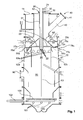
- a shaft gasifier is shown, which is bounded by a substantially cylindrical housing 10 with a circumferential housing wall to the environment. At the upper end, a cover 11 is arranged and closes the top of the housing with the exception of a central passage opening 12. Through the passage opening 12, an air supply pipe 20 and a surrounding this air supply pipe surrounding pipe 30 is guided. The air supply tube 20 and the sheath tube 30 extend centrally longitudinally along the central longitudinal axis 13 of the carburetor.
- a filling opening 40 which is closable by means of a cover 41 and adjoins a sloping from top to bottom, with respect to the central longitudinal axis 13 obliquely extending channel 42 is disposed in the upper region of the carburetor and serves to supply solid.
- the channel 42 opens into a gasification zone 50, in which solid is placed and subjected to pyrolysis.
- the gasification zone 50 is disposed between the outer wall 10 of the gasifier and a central oxidation chamber 60 and is separated from the oxidation zone 60 by a cylindrical wall 61.
- the gasification zone 50 is of annular design and surrounds the oxidation zone 60 on all sides in a horizontal cross section.
- air inlet nozzles 71a, c 72a, c which extend in the radial direction to the central longitudinal axis 13 and are introduced in a circumferential row in the housing wall 10, air with an oxygen content.
- the air supply pipes 71a, c 72a, c are arranged in a total of two planes and distributed uniformly over the circumference of the carburetor.
- the air inlet nozzles 71a, c are surrounded by an externally attached to the housing 10 annular channel 75a, c, through which the air is circumferentially distributed to all air inlet nozzles. Air is introduced from outside into the annular channel 75a, c via openings 76a, c. In the same way, the air inlet nozzles 72a, c are surrounded by an annular channel 77a, c arranged externally on the housing 10, can enter the air via openings 78a, c and via which the air is distributed circumferentially to all the air inlet nozzles 71a, c 72a, c.
- annular space 31 is formed through which also air is passed, which is supplied via an air inlet pipe 32 to the annular space 31 from an air source.
- air inlet pipe 32 For this annular space 31, the air enters a total of four circumferentially distributed and offset by 90 ° to each other air pipes 33, 34, which extend radially from the annular space 31, starting outwards. From the air pipes 33, 34, the air exits at the outer end and is deflected obliquely downward into the annular gasification zone 50.
- the gasification zone 50 is supplied with air from outside via the air inlet nozzles 71a, c, 72a, c, and air is supplied from the inside via the air pipes 33, 34, resulting in a uniform penetration of the solids in the gasification zone 50 with air.
- the oxidation zone 60 is covered by a conical housing section 62 sloping downwardly from above, thereby facilitating the supply of solids from the feed channel 42 into the gasification zone 50 solely by gravity.
- the pyrolysis gas obtained in the gasification zone 50 by pyrolysis passes through openings 63 a-d, which are distributed on a horizontal plane circumferentially on a cylindrical housing 61 in the oxidation zone.
- the raw gas is substoichiometrically converted by partial oxidation and thermal cracking into short carbon chains at a temperature of about 1000 ° C or more.
- air is supplied via the air supply tube 20 of the oxidation zone via an air inlet channel 21 as an oxidizing agent, which exits from a plurality of circumferentially distributed at the lower end of the air supply pipe 20 openings 22.
- an end-side axial opening 23 is arranged, which serves to receive an upper temperature sensor.
- the solids pyrolyzed in the gasification zone 50 continue to slide downwards due to gravity and are conveyed through obliquely outwardly downwardly arranged conical baffles into an inner, cylindrically delimited reduction zone 80. This promotion is also solely due to the influence of gravity.
- the partially oxidized in the oxidation zone and thermally cracked raw gas is withdrawn via a discharge channel 90, which is inserted into the housing wall 10 at the lower end of the carburetor.
- the entire gas flow guide within the carburettor is effected solely by a vacuum applied to the exhaust duct 90, with which the fuel gas is withdrawn from the carburetor.
- the temperature in the gasification zone is measured by means of temperature sensors inserted in openings 51a, c.
- four openings 51a-d offset by 90 ° are provided (the openings 51b, d are outside the cutting plane and are not visible or hidden by the oxidation zone).
- the temperature in the degassing sectors can be measured separately, as follows Fig. 3 described in more detail.
- the temperature in the oxidation zone can be measured by means of a temperature probe.
- the temperature thus measured represents a reliable value for the process temperature in the oxidation zone and is used to control the supply of the oxidizing agent, in this case the air, by means of a control device in the oxidation zone as an input variable.
- the partially oxidized and thermally cracked raw gas flows through the coke located above a grate 100, which is produced from the solid gasified in the gasification zone 50 and falls downwards.
- the raw gas is passed through the stored on the grid 100, fully degassed coke and thereby filtered and chemically reduced.
- the raw gas then ultimately withdrawn through the opening 90 is therefore of high quality and extremely low in tar.
- the grate 100 is guided by means of rollers 101 for a translational reciprocal movement and can be coupled by means of a rod 102 to a corresponding actuator.
- the movement of the grate causes fine ashes and particles to fall through into a collecting space 103.
- the rust movement is controlled as a function of a pressure difference.
- the pressure difference is calculated from the negative pressure at the outlet duct 90 and the ambient pressure. When a predetermined pressure difference is exceeded, a rust movement is performed until the pressure difference has dropped below a lower, predetermined value.
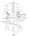
- Fig. 2 shows a section of a second embodiment.
- an oxidation zone 160 which is delimited by a cylindrical wall 161.
- the oxidation zone 160 is bounded at its upper end by a conical housing wall 162, in which an air supply pipe 120 and a sheath tube 130 enclosing it is inserted.
- the air supply pipe and the sheath tube is rotatably supported and can rotate about the longitudinal axis 113 of the carburetor. This will both the housing wall 162 as well as the housing wall 161 set in rotation about the central longitudinal axis 113, which prevents deposition of pyrolysis gas constituents and the formation of constituent layers on these walls.
- a plurality of blades 164 a-f are attached to the cylindrical housing wall 161.
- Each blade 164 a-f extends from the housing wall 161! radially outward and thus penetrates the gasification zone.
- the blades 164 a-f are vertically staggered to each other along a helical line on the housing wall 161. As the housing 161 rotates, the blades 164a-f effect mixing and loosening by means of upward transport of the particulate matter disposed in their zone in the gasification zone thereby producing a homogeneous and efficient gasification of this solid.
- the air inlet nozzles 171a, c, 172a, c are arranged above the plane in which the uppermost blades 164 a-f are located, where they introduce air into the gasification zone from the outside.
- air is supplied from the inside via the annular space between the sheath tube 130 and the air supply tube 120.
- Fig. 3 For example, a horizontal cross section through the carburetor is shown at the level of the openings in the oxidation chamber wall 61 and 161 and the air inlet nozzles 171a, c, respectively. How out Fig. 3 can be seen, enters from an annular channel 175 ad through a plurality of radially formed in the housing 110 openings 171a-d air in the gasification zone 150a-d.
- the annular channel is subdivided into four annular channel sectors 175a-d by means of radially extending partition walls 179a-d, which are spaced apart by 90 ° in the circumferential direction. Air may enter each annular channel sector 175a-d via one air inlet port 176a-d, respectively, and this air supply may be individually controlled in amount for each annular channel sector 175a-d.
- the air enters the gasification zone via respective air inlet nozzles 171a-d respectively associated with each ring channel sector.
- This effects a functional separation of the gasification zone into four gasification sectors 150a-d with regard to the air supply and consequently the temperature control.
- the temperature is measured individually and the air supply is controlled or regulated accordingly.
- the air supply to each gasification sector is controlled individually via a corresponding throttle by means of a control device 155.
- the air supply is increased, at too high a temperature for optimum pyrolysis, the air supply is throttled.
- a separate temperature measuring probe and an air supply device to be controlled separately are provided for each gasification sector to be controlled separately.
- the control / reboiling can be done via a single or a common electronic control unit.
- the pyrolysis gas enters the central oxidation zone 160 via openings 163 where it is converted by partial oxidation and thermal cracking. From there, the raw gas enters down into the reduction zone and is withdrawn via the exhaust pipe from the carburetor.
Landscapes
- Chemical & Material Sciences (AREA)
- Engineering & Computer Science (AREA)
- Combustion & Propulsion (AREA)
- Oil, Petroleum & Natural Gas (AREA)
- Organic Chemistry (AREA)
- Mechanical Engineering (AREA)
- Processing Of Solid Wastes (AREA)
Description
- Die Erfindung betrifft eine Vergasungseinrichtung zur Erzeugung eines entzündbaren Gases aus einem Feststoff, umfassend:
- eine Vergasungszone, in die über eine Einfüllöffnung der Feststoff einfüllbar ist,
- eine Oxidationszone zur Oxidation des erzeugten Gases ausgebildet ist, die mit der Vergasungszone zur Leitung des in der Vergasungszone erzeugten Gases in die Oxidationszone verbunden ist.
- Ein weiterer Aspekt der Erfindung ist ein Vergasungsverfahren zur Erzeugung eines entzündbaren Gases aus einem Feststoff.
- Vergasungseinrichtungen oder auch Vergaser oder Gaserzeuger der vorgenannten Bauart und Vergasungsverfahren werden dazu verwendet, um feste Stoffe, wie organische oder anorganische, kohlenstoffhaltige Materialien, insbesondere Holz, Pflanzen oder Pflanzenreste, insbesondere in pelletierter Form, in einem kontrollierten Verfahren möglichst vollständig zu vergasen, um hierdurch ein zündfähiges, insbesondere brennbares Gas zu erzeugen. Typischerweise wird dieses so erzeugte Gas in einem der Vergasung nachgeschalteten Prozess verbrannt, um hierdurch Arbeit zu verrichten und beispielsweise einen Stromerzeuger zu betreiben.
- Aus
EP 1 865 046 A1 sind ein Vergaser und ein Vergasungsverfahren bekannt, welches in einem Schachtvergaser in einem dreistufigen Prozess durch Vergasung des Feststoffs, partielle Oxidation und thermische Aufspaltung des Gases und Reduktion ein zündfähiges Gas erzeugt. Die Offenbarung dieser Patentanmeldung wird durch Bezugnahme vollständig in die OffenbarungEP 1 865 046 A1 einbezogen. Nachteilig an dem in dieser Patentanmeldung offenbarten Stand der Technik ist, dass die Vergasung oftmals nur unvollständig gelingt und die in dem Feststoff liegende Energiemenge dadurch nicht vollständig ausgeschöpft wird. Ein weiterer Nachteil des solcherart vorbekannten Verfahrens bzw. Vergasers liegt darin, dass der Vergaser bei bestimmungsgemäßem Betrieb zur Verschmutzung neigt und hierdurch verhältnismäßig kurze Wartungsintervalle für seine regelmäßige Reinigung erforderlich sind. - Aus
DE 1 037 051 ,DE 198 46 805 undDE 102 58 640 sind weitere Vergasungsverfahren und Vergaser bekannt, welche dazu dienen, Feststoffe in ein zündfähiges Gas zu vergasen. Auch diese vorbekannten Verfahren weisen den Nachteil auf, dass sie die in dem Feststoff ruhende Energiemenge nicht vollständig in Form eines brennbaren Gases ausschöpfen, da der Vergasungsprozess darin nicht in einer optimalen Weise abläuft und dass eine regelmäßige Wartung in kurzen Zeitintervallen erforderlich ist, um die Funktionsfähigkeit der Vergaser bzw. die Wirksamkeit des Vergasungsverfahrens sicherzustellen. - Aus
US 2009/0282738 ist eine Vorrichtung und ein Verfahren zum Erzeugen von Biotreibstoff bekannt, welche allgemein konzentrische Kammern aufweist, beinhaltend eine Verbrennungskammer und wenigstens eine Pyrolysekammer.US 2007/0006528 zeigt ein Verfahren und eine Vorrichtung zum Erzeugen eines Brenngases aus Biomasse. Die Vorrichtung umfasst mehrere Level, wobei jeder Level jeweils mehrere sich radial erstreckende Luftzufuhrrohre umfasst. Die Luftzufuhrrohre sind über den Umfang verteilt. Jeder Level wird mit variablen Luftmengen beaufschlagt. - Es ist Aufgabe der vorliegenden Erfindung, einen Vergaser bzw. ein Vergasungsverfahren bereitzustellen, welches eine effizientere Vergasung eines Feststoffs erreicht. Es ist ein Ziel der Erfindung, die Zeitintervalle, die zwischen zwei notwendigen Wartungsintervallen bei bestimmungsgemäßem Verbrauch der Vergasungseinrichtung liegen, gegenüber dem Stand der Technik bei gleichbleibender Effizienz zu verlängern oder bei gesteigerter Effizienz zumindest beizubehalten, vorzugsweise zu verlängern.
- Diese Aufgabe wird erfindungsgemäß durch eine Vergasungseinrichtung nach Anspruch 1 gelöst.
- Mit der erfindungsgemäßen Vergasungseinrichtung wird eine Vergasungszone bereitgestellt, die funktionell hinsichtlich der Temperaturführung und Luftzufuhr in zumindest zwei, vorzugsweise mehr als zwei Vergasungssektoren aufgeteilt ist. Eine funktionelle Aufteilung kann beispielsweise erreicht werden, indem die Vergasungssektoren zwar nicht durch konstruktive Elemente voneinander getrennt sind, sondern stattdessen für jeden Vergasungssektor eine separate Luftzufuhr bereitgestellt ist und der Vergasungssektor im Wesentlichen oder zumindest in einem für die Temperaturführung maßgeblichen Anteil aus der für ihn bereitgestellten Luftzufuhr mit Luft versorgt wird. So kann eine zwar insgesamt zusammenhängende und nicht konstruktiv aufgeteilte Vergasungszone bereitgestellt sein, die aber quasi virtuell aufgrund der separaten Luftzufuhr in definierte Vergasungssektoren funktionell aufgeteilt ist.
- Zusätzlich kann die Vergasungszone auch durch Trennelemente wie Trennwände oder dergleichen solcherart aufgeteilt sein, dass ein Übertritt von Feststoff und Gas aus einem Vergasungssektor in einen anderen Vergasungssektor nicht unmittelbar möglich ist, insbesondere nicht auf direktem Weg, so dass der Vergasungsprozess in jedem Vergasungssektor als weitestgehend isolierter Prozess stattfindet.
- Erfindungsgemäß wird in jedem Vergasungssektor die dort herrschende Temperatur erfasst. Hierzu ist eine entsprechende Temperaturmesseinrichtung vorhanden, die beispielsweise mittels eines einzelnen Temperaturmessinstrumentes in aufeinanderfolgenden Messzyklen die Temperatur der einzelnen Vergasungssektoren misst oder welches mehrere Temperaturmessgeräte umfasst und jeweils ein Temperaturmessgerät einem Vergasungssektor zugeordnet ist.
- Die Temperaturmesseinrichtung ist signaltechnisch mit einer Steuerungseinheit gekoppelt, die dazu dient, die Temperatur in jedem Vergasungssektor in einem für die Vergasung optimalen Bereich einzustellen. Es ist zu verstehen, dass die Steuerungseinrichtung insbesondere einen geschlossenen Regelvorgang in einem Regelkreis regeln kann. Die Steuerungseinrichtung ist wiederum signaltechnisch mit einer Luftzuführungseinheit gekoppelt, die dazu ausgebildet ist, jedem Vergasungssektor Luft zuzuführen. Dabei kann jedem Vergasungssektor eine für die in diesem Vergasungssektor vorherrschenden Bedingungen ideale Luftmenge zugeführt werden oder in bestimmten Situationen keine Luft zugeführt werden. Grundsätzlich ist für den Fall, dass in einem Vergasungssektor eine zu niedrige Temperatur, d.h. eine Temperatur unterhalb der idealen Prozesstemperatur herrscht, eine Zufuhr von Luft oder eine verstärkte Zufuhr von Luft durch die Luftzuführungseinrichtung vorzusehen und im umgekehrten Falle, d.h. einer zu hohen, oberhalb der idealen Prozesstemperatur liegenden Temperatur in einem Vergasungssektor ist, die Luftzufuhr zu diesem Vergasungssektor zu reduzieren.
- Anstelle einer Temperaturmesseinheit kann erfindungsgemäß auch eine andere Erfassungseinrichtung verwendet werden, welche einen direkten oder indirekten Rückschluss auf die Effizienz der Vergasungsvorgangs in dem jeweiligen Sektor zulässt, beispielsweise eine Analysevorrichtung zur Bestimmung der Zusammensetzung des Pyrolysegases oder Teilen davon.
- Mit der erfindungsgemäß fortgebildeten Vergasurigseinrichtung wird eine Vergasung eines Feststoffs in einer großen Vergasungszone erzielt, ohne dass hierbei der Nachteil auftritt, dass durch lokal bedingte Effekte, beispielsweise eine Ansammlung besonders großer und dichter Mengen von Feststoff in einem Bereich der Vergasungszone oder einer ungünstigen Luftzufuhr in einen Bereich der Vergasungszone die Vergasung ungünstig verläuft. Dies wird erfindungsgemäß erreicht, indem die Vergasungszone in zumindest zwei, vorzugsweise mehrere Sektoren, beispielsweise vier sich jeweils über einen Umfangsabschnitt von 90° erstreckende Vergasungssektoren aufgeteilt wird und die Vergasung anhand der darin vorherrschenden Temperatur und deren Regelung bzw. Steuerung durch Luftzufuhr in jedem Vergasungssektor separat gesteuert bzw. geregelt wird. Grundsätzlich können die Vergasungssektoren gleichmäßig oder ungleichmäßig über den Umfang verteilt sein und zwei, drei, vier, fünf oder mehr Sektoren vorgesehen sein.
- Die Oxidationszone ist bezogen auf ihren Querschnitt zumindest teilweise, vorzugsweise vollständig von der Vergasungszone umgeben. Demgemäß ist die Oxidationszone zentral innerhalb der Vergasungseinrichtung angeordnet, indem sie in Bezug auf einen Querschnitt durch die Vergasungseinrichtung zumindest in einem Bereich, vorzugsweise aber vollständig von der Vergasungszone umgeben ist. Hierdurch wird insbesondere eine ringförmige Vergasungszone um die Oxidationszone ausgebildet und folglich ein wirksamer Wärmeübergang von der Vergasungszone in die Oxidationszone und umgekehrt ermöglicht. Dabei ist zu verstehen, dass einerseits durch die Zufuhr von Pyrolysegas aus der Vergasungszone in die Oxidationszone ein konvektiver Wärmetransport stattfindet, durch die Umgebung der Oxidationszone mit der Vergasungszone aber darüber hinaus auch durch direkte Wärmeleitung ein Wärmetransport stattfinden kann. Insbesondere kann diese Ausführungsform solcherart verwirklicht werden, dass die Vergasungseinrichtung als Schachtvergaser ausgeführt ist und die Oxidationszone als zentral innerhalb des Schachtvergasers angeordnete Oxidationskammer ausgeführt ist, die von einer ringförmigen Vergasungszone umgeben ist.
- Es ist bevorzugt, die Vergasungseinrichtung durch ein Luftzuführungsrohr fortzubilden, welches an seinem ersten Ende mit der Oxidationszone verbunden ist, insbesondere in die Oxidationszone hineinragt, und mit seinem anderen Ende mit einer Quelle für sauerstoffhaltige Luft verbunden ist. Diese Fortbildung ist sowohl in Verbindung mit der zuvor erläuterten, in mehrere benachbarte Vergasungssektoren aufgeteilten Vergasungszone und der hiermit in Verbindung stehenden Temperaturmesseinheit, Steuerungseinheit und Luftzufuhreinrichtung ausführbar oder auch unabhängig und ohne eine solcherart aufgeteilte Vergasungszone, Temperaturmesseinheit, Steuerungseinheit und/oder Luftzufuhreinrichtung. Durch das Luftzuführungsrohr kann der Oxidationszone in wirksamer Weise Luft zugeführt werden, um die dortige Oxidation des Pyrolysegases auszuführen bzw. zu forcieren. Das Luftzuführungsrohr erstreckt sich dabei vorzugsweise ausgehend von einem oberen Ende der Vergasungseinrichtung in Längsrichtung, insbesondere entlang der Mittelachse der Vergasungseinrichtung, nach unten in Richtung der Oxidationszone.
- Dabei ist es weiter bevorzugt, dass das Luftzuführungsrohr zumindest abschnittweise in einem Umhüllungsrohr angeordnet ist und ein Ringraum zwischen dem Luftzuführungsrohr und dem Umhüllungsrohr ausgebildet ist, der an seinem ersten Ende mit der Vergasungszone verbunden ist und mit seinem anderen Ende mit einer Quelle für sauerstoffhaltige Luft verbunden ist.
- Durch ein solches Umhüllungsrohr wird es ermöglicht, zusätzlich zu der Luft, die durch das Luftzuführungsrohr der Oxidationszone zugeführt wird, weiterhin Luft mit darin enthaltenem Sauerstoff in einen anderen Bereich, insbesondere in die Vergasungszone zuzuführen. Dieser Fortentwicklung liegt die Erkenntnis zugrunde, dass gerade dann, wenn Feststoffe einer effizienten Vergasung unterzogen werden sollen, es vorteilhaft ist, wenn die Luftzufuhr in einer ausgeglichenen und gleichmäßigen Weise erfolgt, d.h. es werden hohe lokale Strömungsgeschwindigkeiten vermieden, zugleich aber ein ausreichend hoher Volumenstrom bereitgestellt, um eine möglichst vollständige und effiziente Vergasung zu erzielen. Hierbei hat sich die Einbringung der Luft über mehrere Zuführungsquellen und -leitungen als besonders vorteilhaft erwiesen. Grundsätzlich kann der Vergasungszone, wie im Stand der Technik beschrieben, die zur Vergasung benötigte Luft von außen zugeführt werden, beispielsweise über mehrere von außen in die Vergasungszone hinein ragende Luftzutrittsrohre oder -düsen. Insbesondere dann, wenn aber die Vergasungszone sich über einen solchen Querschnitt erstreckt, dass hierbei Querschnittsanteile ebenfalls eine effiziente Vergasung erzielen sollen, die von dieser Luftzufuhr von außen beabstandet liegen, ist es vorteilhaft, eine weitere, in der Nähe dieser Querschnittsbereiche mündende Luftzufuhr bereitzustellen. Dies kann durch das Umhüllungsrohr wirksam erfolgen. Das Umhüllungsrohr kann grundsätzlich so angeordnet sein, dass es im Inneren der Vergasungseinrichtung verläuft, insbesondere, sofern die Vergasungseinrichtung als Schachtvergaser ausgebildet ist, entlang und parallel, vorzugsweise koaxial zur Längsachse des Schachtvergasers. Hierdurch wird eine Einbringung von Luft in einen zentralen Bereich der Vergasungszone, insbesondere in demjenigen Bereich der Vergasungszone, der unmittelbar an die Oxidationszone angrenzt, ermöglicht.
- Dabei ist zu verstehen, dass dann, wenn die Vergasungszone in mehrere Vergasungssektoren aufgeteilt ist, auch das Umhüllungsrohr derart ausgestaltet sein, dass es separate Luftführungsleitungen aufweist, insbesondere in gleicher Anzahl wie der Anzahl der Vergasungssektoren, um die über den Ringraum zwischen Umhüllungsrohr und Luftzuführungsrohr geleitete Luft individuell den Bedürfnissen in dem jeweiligen Vergasungssektor anpassen zu können. Dies kann beispielsweise durch sich radial erstreckende Trennwände erreicht werden, durch welche der Ringraum in mehrere Ringraumsektoren aufgeteilt wird und diese Ringraumsektoren individuell mit einem Luftmassenstrom beaufschlagt werden.
- Grundsätzlich ist dabei weiterhin zu verstehen, dass unter dem Begriff "Luft" insbesondere Umgebungsluft verstanden werden kann, hierbei aber auch Gase oder Gasgemische zu verstehen sind, die von der Zusammensetzung der Umgebungsluft abweichen, insbesondere beispielsweise Gasgemische, die einen erhöhten Anteil von Sauerstoff enthalten oder Gasgemische, denen Anteile zugemischt werden, die als Katalysator wirken oder die besondere vergasungs- oder oxidationsfördernde Anteile enthalten oder Anteile, welche Ablagerungen innerhalb der Vergasungseinrichtung vermeiden, aufweisen. Bei diesen Anteilen kann es sich insbesondere um gasförmige Anteile handeln. Darüber hinaus können die Anteile aber auch in flüssiger Form, beispielsweise in Form eines Aerosols oder in fester Form, beispielsweise in Form eines Pulvers beigemengt werden. Insbesondere kann die zugeführte Luft in bestimmten Prozesssituationen mit Wasser oder Wasserdampf angereichert werden, um die Pyrolyse bzw. Vergasung oder Oxidation oder, wie nachstehend erläutert, Reduktion, vorteilhaft zu beeinflussen.
- Gemäß einer weiteren bevorzugten Ausführungsform ist vorgesehen, dass die Oxidationszone in einer Oxidationskammer angeordnet ist, die von einer oder mehreren Wänden begrenzt ist, insbesondere gegenüber der Vergasungszone begrenzt ist, und dass zumindest Segmente dieser Wände, vorzugsweise alle Wände, bewegbar in Bezug auf die Vergasungszone geführt sind, insbesondere drehbar geführt sind. Hierbei ist zu verstehen, dass diese Fortbildung in Kombination mit der zuvor erläuterten Aufteilung der Vergasungszone in Vergasungssektoren und der Temperaturmesseinheit sowie der Steuerungseinheit und/oder der Luftzufuhreinrichtung oder ohne diese Aufteilung und Einheiten bzw. Einrichtungen ausgeführt sein kann, d.h. insoweit eine unabhängige Fortbildung einer Vergasungseinrichtung der eingangs erläuterten Bauweise darstellt.
- Durch die Möglichkeit nach dieser Fortbildung, die Wände zumindest teilweise, insbesondere aber insgesamt zu bewegen, wird eine Relativbewegung zwischen den in der Vergasungseinrichtung gelagerten Feststoffen und den bewegten Wänden erreicht, wodurch der Aufbau einer an diesen Wänden anhaften Feststoffschicht, beispielsweise durch Niederschläge aus den Pyrolysegasen, wirksam verhindert werden kann. Diese sich aufbauenden Niederschläge bzw. Ablagerungen können einerseits die Effizienz der Vergasung herabsetzen, andererseits die genannte Funktionsweise der Vergasungseinrichtung beeinträchtigen oder stören. Insbesondere kann die Bewegung als Rotationsbewegung ausführt sein, beispielsweise um die Längsachse der Vergasungseinrichtung, insbesondere, wenn die Vergasungseinrichtung als Schachtvergaser ausgeführt ist. Es sind jedoch auch andere Bewegungsformen denkbar, beispielsweise translatorische Bewegungen. Die Bewegungsform kann einerseits eine kontinuierliche Bewegung in einer Richtung sein, abweichend hiervon sind aber in bestimmten Anwendungen auch reziproke, d.h. hin- und hergehende Bewegungsformen mit einer regelmäßigen Bewegungsrichtungsumkehr vorteilhaft.
- Dabei kann, sofern ein Luftzuführungsrohr vorgesehen ist, insbesondere vorgesehen sein, dass die Wände beziehungsweise Wandsegmente mit dem Luftzuführungsrohr mechanisch gekoppelt sind zur Übertragung einer Bewegung, insbesondere einer Drehbewegung und vorzugsweise ein Aktuator bereitgestellt ist, der mit dem Luftzuführungsrohr gekoppelt ist zur Einbringung der Bewegung, bzw. der Drehbewegung. Durch diese mechanische Kopplung wird eine wirksame und konstruktiv zuverlässige Übertragung der Bewegung auf die Wand bzw. Wände erreicht, welche die Oxidationszone definieren bzw. begrenzen. Insbesondere kann über das Luftzuführungsrohr sowohl eine translatorische Bewegungsrichtung, beispielsweise in Längsrichtung einer als Schachtvergaser ausgeführten Vergasungseinrichtung oder einer rotatorischen Bewegung, beispielsweise um die Längsachse einer als Schachtvergaser ausgebildeten Vergasungseinrichtung realisiert werden oder eine hieraus zusammengesetzte Bewegungsform.
- Dabei ist es noch weiter bevorzugt, wenn an einer oder mehreren Wänden der Oxidationskammer ein oder mehrere Schaufelelemente angeordnet sind, welche sich von den Wänden ausgehend in die Vergasungszone erstrecken und ausgebildet sind, um durch Bewegung der Wand bzw. des Wandsegments, an dem sie befestigt sind, eine Förder-, Zerkleinerungs- oder Mischbewegung in dem Feststoff in der Vergasungszone zu bewirken. Solche Schaufelelemente, die beispielsweise in Gestalt von Paddeln, Stäben, Flügeln mit oder ohne einer Verwindung ausgeführt sein können, bewirken eine Vermischung und ggf. eine Zerkleinerung und/oder Förderung in dem Feststoffbereich, in den sie sich erstrecken, wenn sie sich relativ zu diesem bewegen. Die Schaufelelemente können zu diesem Zweck auf einer Ebene oder gestaffelt zueinander, beispielsweise entlang einer Schraubenlinie an der Außenfläche der Wände, welche die Oxidationszone begrenzen, angeordnet sein und hierbei insbesondere umfänglich um eine Längsachse einer als Schachtvergaser ausgeführten Vergasungseinrichtung angeordnet sein. Solche Schaufelelemente können sowohl bei einer translatorischen, insbesondere aber bei einer rotierenden Bewegung des Wandelements bzw. der Wand / Wände, an denen sie befestigt sind, zu einer homogeneren Zusammensetzung der Feststoffe im Bereich der Vergasungszone beitragen und hierdurch eine effizientere Vergasung erzielen.
- Noch weiter ist zu bevorzugt, die erfindungsgemäße Vergasungseinrichtung fortzubilden durch eine Reduktionszone, welche mit der Oxidationszone zur Zuleitung des in der Oxidationszone gebildeten Rohgases verbunden ist und ausgebildet ist, um das ihr zugeleitete Rohgas zu reduzieren. In der Reduktionszone kann insbesondere mithilfe von Koks, der aus der Vergasungszone in die Reduktionszone befördert wird und sich aus entgasten Feststoffresten zusammensetzt, ein Brenngas aus dem in der Oxidationszone aufbereitetem Pyrolysegas erzeugt werden. Hierbei kann weiterhin auch eine Filterung von Festbestandteilen durch den Koks in der Reduktionszone erzielt werden. Alternativ oder zusätzlich hierzu können aber auch andere Verfahren zur Filterung, beispielsweise mittels Filterkerzen oder dergleichen vorgesehen sein.
- Noch weiter ist es bevorzugt, die erfindungsgemäße Vergasungseinrichtung fortzubilden, indem sie umfasst: eine Anordnung der Vergasungszone und der Oxidationszone in einem Schachtvergaser, welcher eine am oberen Ende angeordnete Befüllungsöffnung zur Befüllung mit dem zu vergasenden Feststoff aufweist, in dem die Vergasungszone unterhalb der Befüllungsöffnung angeordnet ist und die Vergasungszone zumindest abschnittsweise ringförmig ausgebildet ist und die Oxidationszone umgibt, wobei die Oxidationszone vorzugsweise zentral in Bezug auf den Querschnitt des Schachtvergasers angeordnet ist und ein bzw. das Luftzuführungsrohr sich ausgehend von der Oxidationszone entlang der Längsachse des Schachtvergasers erstreckt und drehbar gelagert ist zur Übertragung einer Drehbewegung auf eine die Oxidationszone begrenzende Wand oder mehrere die Oxidationszone begrenzende Wände.
- Mit der so fortgebildeten Vergasungseinrichtung wird ein Schachtvergaser bereitgestellt, in dem eine Vergasungszone und eine Oxidationszone in benachbarter Lage solcherart zueinander angeordnet sind, das die Oxidationszone als zentrale Oxidationskammer ausgebildet ist und von der Vergasungszone umgeben und folglich von einer als Gehäuse dienenden Außenwand des Schachtvergasers beabstandet ist. Der Schachtvergaser kann insbesondere zylindrisch, d.h. im Querschnitt rund ausgeführt sein, wodurch eine durch runde Seitenwände begrenzte, ringförmige Vergasungszone sich darin ausbilden lässt. In anderen Ausführungsformen sind jedoch auch andere geometrische Gestaltungen des Schachtvergasers, beispielsweise mit einem rechteckigen oder quadratischen Querschnitt vorteilhaft, in diesem Fall wird die ringförmige Vergasungszone durch entsprechend ausgebildete, zusammenhängende Spaltabschnitte zwischen der das Gehäuse bildenden Außenwand des Schachtvergasers und den die Oxidationszone begrenzenden Wänden definiert. Grundsätzlich ist hierbei zu verstehen, dass im Schachtvergaser eine durch Schwerkraft bedingte, insbesondere ausschließlich durch Schwerkraft erzeugte Beförderung der Feststoffe von einer oberen Einfüllöffnung für frisches, unvergastes Material und einer unteren Ausfuhröffnung für entgastes Material (Koks) bewirkt wird, wobei eine durch Schaufelelemente, wie zuvor beschrieben, bewirkte lokale Vermischung oder Förderung des Feststoffes in oder entgegen der Schwerkraftrichtung hierbei von der Erfindung mitumfasst ist und auch unter einer generellen schwerkraftbedingten Beförderung des Feststoffs verstanden wird.
- Die Ausführungsform als Schachtvergaser nach dieser Fortbildung kann insbesondere mit den zuvor erläuterten Merkmalen, wie beispielsweise dem Luftzuführungsrohr, dem hierzu angeordneten Umhüllungsrohr zur Zuführung von Luft in den innenliegenden Bereich der Vergasungszone und / oder der Aufteilung der Vergasungszone in mehrere Vergasungssektoren mit einer entsprechenden Temperaturmesseinheit, Steuerungseinheit und Luftzuführungseinrichtung fortgebildet werden. Dabei ist zu verstehen, dass die Ausbildung als Schachtvergaser sich insbesondere dazu eignet, um mit den im kennzeichnenden Teil der Ansprüche 1 und / oder 3 und / oder 5 definierten Fortbildungen in isolierter Weise oder kombinierter Weise fortgebildet werden kann und hierbei auch entsprechende Fortbildungen nach den weiteren Unteransprüchen vorgesehen werden können.
- Dabei ist es bei der zuvor beschriebenen Ausführungsform als Schachtvergaser besonders bevorzugt, eine Reduktionszone vorzusehen, die unterhalb der Vergasungszone angeordnet ist und den direkten Übertritt von Feststoff aus der Vergasungszone in die Reduktionszone ermöglicht und vorzugsweise ein Abschnitt der Oxidationszone so angeordnet ist, dass er die Vergasungszone in Strömungsrichtung des erzeugten Gases von der Reduktionszone trennt. In dieser Reduktionszone kann, wie zuvor erläutert, aus dem pyrolisierten und oxidierten bzw. gecrackten Rohgas aus der Oxidationszone ein Brenngas zur Erzeugung und hierbei eine zusätzliche Filterwirkung zu erzielen.
- Dabei ist es weiterhin bevorzugt, dass die Reduktionszone zur Aufnahme von pyrolisiertem Feststoff aus der Vergasungszone ausgebildet ist und so angeordnet ist, dass der pyrolisierte Feststoff durch Schwerkraftwirkung aus der Vergasungszone in die Reduktionszone gelangt und am unteren Ende der Reduktionszone ein bewegliches Rost angeordnet ist zur Siebung der in der Reduktionszone nach unten fallenden Asche. Mit dieser Fortbildung wird eine besonders wirksame Reduktion in der Reduktionszone erzielt. Weiterhin ist zu verstehen, dass der Rost einerseits translatorisch reziprok oder kontinuierlich rotierend bewegbar ist, um ein Durchfallen von kleinen Koks- und Ascheanteilen in eine darunterliegende Kammer zu befördern, andererseits der Rost auch vertikal beweglich sein kann, um hierdurch die Höhe der Reduktionszone zu verändern und an den Prozessablauf bzw. die zugeführten Feststoffe anpassen zu können.
- Die erfindungsgemäße Vergasungeinrichtung kann weiter fortgebildet werden durch eine Druckmessvorrichtung, die zur Messung einer Druckdifferenz über zumindest einen Teil des Strömungsweges des erzeugten Gases innerhalb der Vergasungseinrichtung ausgebildet und mit einer Steuerungseinrichtung signaltechnisch gekoppelt ist, die mit einem Aktuator zur Bewegung eines Rostes signaltechnisch gekoppelt ist, der bei Bewegung Feinanteile aus der Feststoffschüttung innerhalb der Reduktionszone in einen Sammelraum abführt, wobei die Steuerungseinrichtung ausgebildet ist, um den Aktuator zu betätigen, wenn eine vorbestimmte Druckdifferenz überschritten wird und vorzugsweise ausgebildet ist, die Aktuatorbetätigung zu beenden, wenn eine niedrigere, vorbestimmte Druckdifferenz unterschritten wird. Mit dieser Fortbildung wird eine druckabhängige Abfuhr der Feinanteile innerhalb der Feststoffschüttung bewirkt und damit ein effizienter Betrieb erreicht. Die Druckdifferenz kann dabei insbesondere über den gesamten strömungsweg ausgehend von der Umgebungsluft, die als Frischluft in den Vergaser eintriit bis zu der Austrittsöffnung für das fertig aufbereitete Brenngas aus dem Vergaser gemessen werden.
- Mit dieser Fortbildung wird ein Betriebsverfahren ermöglicht, bei dem eine Druckdifferenz über zumindest einen Teil des Strömungsweges des erzeugten Gases gemessen wird und ein Rost mittels eines Aktuators bewegt wird, um Feinanteile aus der Reduktionszone abzuführen, wenn die gemessene Druckdifferenz einen vorbestimmten Wert überschreitet und vorzugsweise die Bewegung des Rostes beendet wird, wenn die Druckdifferenz einen kleineren, vorbestimmten Wert unterschreitet.
- Es ist zu verstehen, dass diese Ausführungsform als Vorrichtung oder Verfahren auch unabhängig von der Aufteilung der Entgasungszone in mehrere Sektoren und die entsprechenden separaten Luftzufuhreinrichtungen und Temperaturmesseinrichtungen und die hierzu entsprechende Verfahrensführung ausgeführt werden kann.
- Ein weiterer Aspekt der Erfindung ist ein Vergasungsverfahren nach Anspruch 11. Das erfindungsgemäße Vergasungsverfahren kann insbesondere mit der zuvor erläuterten Vergasungseinrichtung ausführt werden und zeichnet sich dadurch aus, dass durch eine besonders wirksame Prozesssteuerung in der Vergasungszone, indem diese in einzelne Prozesskammern in Form der Vergasungssektoren aufgeteilt wird und in diesen Vergasungssektoren eine separate Temperaturüberwachung und -steuerung bzw. -regelung erfolgt, eine besonders effiziente Vergasung erzielt wird.
- Das Vergasungsverfahren kann alternativ oder zusätzlich zu dieser Aufteilung der Vergasungszone in Vergasungssektoren fortgebildet werden, indem die Oxidationszone in einer Kammer angeordnet ist, die von einer oder mehreren Wänden begrenzt ist, die bewegt, insbesondere rotiert werden. Durch diese Bewegung, insbesondere Rotation wird die Bildung von Ablagerungen auf den Wänden bzw. der Wand der Oxidationskammer verhindert oder zumindest reduziert.
- Dabei ist weiterhin vorgesehen, dass an der oder den bewegten Wänden Schaufelelemente angeordnet sind, die sich in die Vergasungszone erstrecken und mittels der Schaufelelemente der Feststoff mechanisch gemischt zerkleinert und / oder gerührt wird. Mittels solcher Schaufelelemente wird eine wirksamen Durchmischung der Feststoffe im Bereich der Vergasungszone erreicht und hierdurch die Vergasung effizienter gestaltet. Schließlich ist bei dem erfindungsgemäßen Vergasungsverfahren weiterhin alternativ zu der Aufteilung der Vergasungszone in mehrere Vergasungssektoren oder in Kombination hiermit und alternativ oder in Kombination mit der Ausgestaltung der Oxidationszone mit bewegten Begrenzungswänden bevorzugt vorgesehen, dass der Oxidationszone über ein Luftzuführungsrohr Luft zugeführt wird und der Vergasungszone über ein das Luftzuführungsrohr umgebendes Umhüllungsrohr Luft zugeführt wird und dass die Wand bzw. Wände der Oxidationszone vorzugsweise mittels des Luftzuführungsrohr in Rotation versetzt werden. Mit dieser Fortbildungsform wird eine besonders effiziente Luftzufuhr in die Vergasungszone erreicht, indem nicht nur, wie im Stand der Technik vorgesehen, die Luftzufuhr von außen über die Außenwände der Vergasungseinrichtung erfolgt, sondern zusätzlich auch eine Luftzufuhr von innen und in den innen liegenden Bereich der Vergasungszone stattfindet. Hierbei ist insbesondere dann, wenn die Vergasungszone in mehrere Vergasungssektoren aufgeteilt ist, zu verstehen, dass das Umhüllungsrohr und der dadurch ausgebildete Ringraum zwischen Umhüllungsrohr und Luftzuführungsrohr auch in mehrere Umfangssektoren aufgeteilt werden kann, um hierdurch die Luft in den einzelnen Vergasungssektoren individuell regelbar und unabhängig voneinander zuführen zu können und die einzelnen Umfangsabschnitte des Ringraums zu diesem Zweck an eine entsprechende individuell regelnde Luftzuführungseinrichtung anschließt. In diesem Zusammenhang kann insbesondere eine entsprechend individuelle Erfassung der Temperaturen in den einzelnen Vergasungssektoren und eine in Abhängigkeit dieser Messgrößen erfolgende Steuerung / Regelung der Luftzufuhr zu den einzelnen Vergasungssektoren erfolgen, wobei zu verstehen ist, dass diese individuelle Luftzufuhr einerseits durch die von außen zugeführte Luft in die einzelnen Vergasungssektoren, andererseits durch die von innen zugeführte Luft in die Vergasungssektoren oder durch beide Zuführungsmaßnahmen erfolgen kann.
- Die Erfindung wird im Weiteren näher durch beispielhafte, nicht beschränkende bevorzugte Ausführungsformen erläutert.
- Es zeigen:
- Fig. 1
- eine längsgeschnittene Seitenansicht einer bevorzugten Ausführungsform der erfindungsgemäßen Vergasungseinrichtung.
- Fig.2
- eine schematische, teilweise längsgeschnittene schematische Seitenansicht eines Details einer zweiten Ausführungsform der erfindungsgemäßen Vergasungseinrichtung und
- Fig. 3
- eine entlang der Linie A-A in
Fig. 2 quergeschnittene schematische Draufsicht eines Details der zweiten Ausführungsform der erfindungsgemäßen Vergasungseinrichtung. - Bezugnehmend zunächst auf
Fig. 1 ist ein Schachtvergaser dargestellt, welcher durch ein im Wesentlichen zylindrisches Gehäuse 10 mit einer umlaufenden Gehäusewandung zur Umgebung hin begrenzt wird. Am oberen Ende ist ein Deckel 11 angeordnet und verschließt die Oberseite des Gehäuses mit Ausnahme einer zentralen Durchtrittsöffnung 12. Durch die Durchtrittsöffnung 12 ist ein Luftzuführungsrohr 20 und ein dieses Luftzuführungsrohr umgebendes Umhüllungsrohr 30 geführt. Das Luftzuführungsrohr 20 und das Umhüllungsrohr 30 erstrecken sich zentral in Längsrichtung entlang der Mittellängsachse 13 des Vergasers. - Eine Einfüllöffnung 40, die mittels eines Deckels 41 verschließbar ist und an die sich ein von oben nach unten abfallender, in Bezug auf die Mittellängsachse 13 schräg verlaufender Kanal 42 anschließt, ist im oberen Bereich des Vergasers angeordnet und dient der Zuführung von Feststoff. Der Kanal 42 mündet in eine Vergasungszone 50, in welcher Feststoff platziert und einer Pyrolyse unterzogen wird.
- Die Vergasungszone 50 ist zwischen der Außenwandung 10 des Vergasers und einer zentralen Oxidationskammer 60 angeordnet und wird durch eine zylindrische Wandung 61 von der Oxidationszone 60 getrennt. Hierdurch ist die Vergasungszone 50 ringförmig ausgestaltet und umschließt in einem horizontalen Querschnitt allseitig die Oxidationszone 60.
- In die Vergasungszone 50 wird über Luftzutrittsdüsen 71a,c 72a,c, die in radialer Richtung zur Mittellängsachse 13 verlaufen und in einer umlaufenden Reihe in die Gehäusewand 10 eingebracht sind, Luft mit einem Sauerstoffgehalt eingeblasen. Die Luftzuführungsrohre 71a,c 72a,c sind in insgesamt zwei Ebenen angeordnet und über den Umfang des Vergasers gleichmäßig verteilt.
- Die Luftzutrittsdüsen 71a,c sind von einem außen am Gehäuse 10 angesetzten Ringkanal 75a, c umgeben, über den die Luft umfänglich auf alle Luftzutrittsdüsen verteilt wird. In den Ringkanal 75a,c wird Luft von außen über Öffnungen 76a,c eingeführt. In gleicher Weise sind die Luftzutrittsdüsen 72a,c von einem außen am Gehäuse 10 angesetzten Ringkanal 77a, c umgeben, in den Luft über Öffnungen 78a, c eintreten kann und über den die Luft umfänglich auf alle Luftzutrittsdüsen 71a,c 72a,c verteilt wird.
- Zwischen dem Luftzuführungsrohr 20 und dem Umhüllungsrohr 30 ist ein Ringraum 31 ausgebildet, durch den ebenfalls Luft geführt wird, welche über ein Luftzutrittsrohr 32 dem Ringraum 31 von einer Luftquelle zugeführt wird. Aus diesem Ringraum 31 tritt die Luft in insgesamt vier umfänglich verteilte und um 90° zueinander versetzte Luftrohre 33, 34 ein, die sich radial von dem Ringraum 31 ausgehend nach außen erstrecken. Aus den Luftrohren 33, 34 tritt die Luft am äußeren Ende aus und wird schräg nach unten in die ringförmige Vergasungszone 50 abgelenkt. Hierdurch wird der Vergasungszone 50 einerseits von außen über die Luftzutrittsdüsen 71a,c, 72a,c Luft zugeführt und andererseits von innen über die Luftrohre 33, 34 Luft zugeführt, was zu einer gleichmäßigen Durchsetzung der Feststoffe in der Vergasungszone 50 mit Luft führt.
- Oberhalb der Luftrohre 33, 34 ist die Oxidationszone 60 durch einen kegelförmigen Gehäuseabschnitt 62, der von oben nach schräg unten abfällt, abgedeckt, wodurch die Zufuhr von Feststoffen aus dem Zuführungskanal 42 in die Vergasungszone 50 alleine aufgrund Schwerkraft erleichtert wird.
- Mittels Temperatursensoren, die in Öffnungen 51a, c und 52a, c eingesetzt sind, wird die Temperatur in der Vergasungszone gemessen.
- Das in der Vergasungszone 50 durch Pyrolyse gewonnene Pyrolysegas tritt durch Öffnungen 63 a-d, die auf einer horizontalen Ebene umfänglich über eine zylindrische Gehäusewandung 61 verteilt sind, in die Oxidationszone ein. In der Oxidationszone wird das Rohgas unterstöchiometrisch durch partielle Oxidation und ein thermisches Cracken in kurze Kohlenstoffketten bei einer Temperatur von etwa 1000°C oder mehr umgewandelt. Hierzu wird über das Luftzuführungsrohr 20 der Oxidationszone über einen Luftzutrittskanal 21 Luft als Oxidationsmittel zugeführt, die aus mehreren umfänglich am unteren Ende des Luftzuführungsrohr 20 verteilten Öffnungen 22 austritt. Am unteren Ende des Luftzutrittsrohres ist eine stirnseitige axiale Öffnung 23 angeordnet, die zur Aufnahme eines oberen Temperatursensors dient.
- Die in der Vergasungszone 50 pyrolysierten Feststoffe rutschen schwerkraftbedingt nach unten weiter und werden durch von schräg außen nach unten innen angeordnete konische Ablenkbleche in eine innen liegende, zylindrisch begrenzte Reduktionszone 80 befördert. Auch diese Beförderung erfolgt alleinig durch Schwerkrafteinfluss. Das in der Oxidationszone partiell oxidierte und thermisch gecrackte Rohgas wird über einen Abzugskanal 90, welcher in die Gehäusewandung 10 am unteren Ende des Vergasers eingesetzt ist, abgezogen. Die gesamte Gasströmungsführung innerhalb des Vergasers wird alleine durch einen am Abzugskanal 90 angelegten Unterdruck bewirkt, mit dem das Brenngas aus dem Vergaser abgezogen wird.
- Die Temperatur in der Vergasungszone wird mittels Temperatursensoren gemessen, die in Öffnungen 51a, c eingesetzt sind. Insgesamt sind vier um 90° versetzte Öffnungen 51a-d vorgesehen (die Öffnungen 51b,d liegen außerhalb der Schnittebene und sind nicht sichtbar bzw. von der Oxidationszone verdeckt). Mittels der Temperatursensoren in den Öffnungen 51a-d kann die Temperatur in den Entgasungssektoren separat gemessen werden, wie nachstehend anhand
Fig. 3 näher beschrieben. - Mittels eines Temperatursondenrohres 65, dass sich von außen in den unteren, von der Luftzufuhr über das Luftzuführungsrohr 20 beabstandeten Bereich der Oxidationszone 60 erstreckt, kann mittels einer Temperatursonde die Temperatur in der Oxidationszone gemessen werden. Die so gemessene Temperatur stellt einen zuverlässigen wert für die Prozesstemperatur in der Oxidationszone dar und wird zur Steuerung/Regelung der Zufuhr des Oxidationsmittels, also hier der Luft, mittels einer Steuerungseinrichtung in die Oxidationszone als Eingangsgröße genutzt.
- Auf dem Weg von der Oxidationszone 60 zu dem Abzugsrohr 90 durchströmt das partiell oxidierte und thermisch gecrackte Rohgas den oberhalb eines Rostes 100 befindlichen Koks, der aus dem in der Vergasungszone 50 vergasten Feststoff entsteht und nach unten fällt. Hierdurch wird das Rohgas durch den auf dem Rost 100 gelagerten, voll entgasten Koks hindurchgeführt und hierbei gefiltert und chemisch reduziert. Das dann letztlich durch die Öffnung 90 abgezogene Rohgas ist folglich von hoher Qualität und äußerst teerarm.
- Der Rost 100 ist mittels Rollen 101 für eine translatorische reziproke Bewegung geführt und kann mittels eines Stabes 102 an einen entsprechenden Aktuator angekoppelt werden. Die Bewegung des Rostes bewirkt ein Durchfallen von feinen Ascheresten und - teilchen in einen Sammelraum 103. Die Rostbewegung wird in Abhängigkeit von einer Druckdifferenz gesteuert. Die Druckdifferenz wird aus dem Unterdruck am Abzugskanal 90 und dem Umgebungsdruck berechnet. Bei Überschreiten einer vorbestimmten Druckdifferenz wird eine Rostbewegung durchgeführt, bis die Druckdifferenz unter einen niedrigeren, vorbestimmten Wert abgesunken ist.
-
Fig. 2 zeigt einen Ausschnitt einer zweiten Ausführungsform. Zu erkennen ist eine Oxidationszone 160, die durch eine zylindrische Wandung 161 begrenzt wird. Wie auch bei der ersten Ausführungsform ist die Oxidationszone 160 an ihrem oberen Ende durch eine kegelförmige Gehäusewand 162 begrenzt, in welcher ein Luftzuführungsrohr 120 und ein dieses umhüllendes Umhüllungsrohr 130 eingesetzt ist. Auch in diesem Fall ist das Luftzuführungsrohr und das Umhüllungsrohr drehbar gelagert und kann sich um die Längsachse 113 des Vergasers drehen. Hierdurch wird sowohl die Gehäusewandung 162 als auch die Gehäusewandung 161 in Rotation um die Mittellängsachse 113 versetzt, was eine Ablagerung von Pyrolysegasbestandteilen und die Bildung von sich aufbauenden Schichten auf diesen Wandungen verhindert. - Darüber hinaus sind an der zylindrischen Gehäusewandung 161 mehrere Schaufeln 164 a-f befestigt. Jede Schaufel 164 a-f erstreckt sich ausgehend von der Gehäusewandung 161 ! radial nach außen und durchdringt daher die Vergasungszone. Die Schaufeln 164 a-f sind vertikal gestaffelt zueinander entlang einer Schraubenlinie an der Gehäusewandung 161befestigt. Bei Rotation des Gehäuses 161 bewirken die Schaufeln 164 a-f eine Durchmischung und Auflockerung mittels einer Aufwärtsbeförderung des in ihrem Bereich angeordneten Feststoffs in der Vergasungszone und erzeugen hierdurch eine homogene und effiziente Vergasung dieses Feststoffs.
- Die Luftzutrittsdüsen 171a, c, 172a,c sind oberhalb der Ebene angeordnet, in der die obersten Schaufeln 164 a-f liegen und führen dort von außen Luft in die Vergasungszone zu. Zusätzlich wird, wie bereits zuvor beschrieben, von innen über den Ringraum zwischen Umhüllungsrohr 130 und Luftzuführungsrohr 120 Luft zugeführt.
- In
Fig. 3 ist ein horizontaler Querschnitt durch den Vergaser auf Höhe der Öffnungen in der Oxidationskammerwandung 61 bzw. 161 und der Luftzutrittsdüsen 171a,c gezeigt. Wie ausFig. 3 ersichtlich, tritt aus einem Ringkanal 175 a-d durch eine Vielzahl von radial in der Gehäusewandung 110 ausgebildeten Öffnungen 171a-d Luft in die Vergasungszone 150a-d ein. - Der Ringkanal ist in vier Ringkanalsektoren 175a-d mittels sich radial erstreckenden Trennwänden 179a-d unterteilt, die in Umfangsrichtung um 90° voneinander beabstandet sind. In jeden Ringkanalsektor 175a-d kann über jeweils eine Luftzutrittsöffnung 176a-d Luft eintreten und diese Luftzufuhr kann hinsichtlich ihrer Menge individuell für jeden Ringkanalsektor 175a-d gesteuert werden.
- Aus den Ringkanalsektoren 175a-d tritt die Luft über jeweils jedem Ringkanalsektor entsprechend zugeordnete Luftzutrittsdüsen 171a-d in die Vergasungszone ein. Hierdurch wird eine hinsichtlich der Luftzufuhr und folglich der Temperaturführung funktionelle Trennung der Vergasungszone in vier Vergasungssektoren 150a-d bewirkt. In jedem Vergasungssektor wird die Temperatur individuell gemessen und die Luftzufuhr entsprechend gesteuert oder geregelt. In Abhängigkeit von der solcherart gemessenen Temperatur wird mittels eines Steuerungsgerätes 155 die Luftzufuhr zu jedem Vergasungssektor individuell über eine entsprechende Drossel geregelt. Bei einer zu niedrigen Temperatur für eine optimale Pyrolyse wird die Luftzufuhr erhöht, bei einer zu hohen Temperatur für eine optimale Pyrolyse wird die Luftzufuhr gedrosselt. Es ist zu verstehen, dass für jeden separat zu steuerenden Vergasungssektor eine separate Temperaturmesssonde und eine separat zu steuernde Luftzufuhreinrichtung vorgesehen ist. Die Steuerung/Regeölung kann über einzelne oder eine gemeinsame elektronische Steuer/Regeleinheit erfolgen.
- Aus den Vergasungssektoren 150a-d tritt das Pyrolysegas über Öffnungen 163 in die zentrale Oxidationszone 160 ein und wird dort durch eine partielle Oxidation und thermische Crackung gewandelt. Von dort tritt das Rohgas nach unten in die Reduktionszone ein und wird über das Abzugsrohr aus dem Vergaser abgezogen.
Claims (15)
- Vergasungseinrichtung zur Erzeugung eines entzündbaren Gases aus einem Feststoff, umfassend:- Eine Vergasungszone (50), in die über eine Einfüllöffnung (40) der Feststoff einfüllbar ist,- Eine Oxidationszone (60) zur Oxidation des erzeugten Gases, die mit der Vergasungszone zur Leitung des in der Vergasungszone erzeugten Gases in die Oxidationszone verbunden ist,
wobei die Vergasungszone in mehrere einander benachbarte Vergasungssektoren (150 a-d) aufgeteilt ist, eine Temperaturmesseinheit (51a,c ) vorhanden ist, die ausgebildet ist, um die in jeweils jedem Vergasungssektor herrschende Temperatur zu messen und die Temperaturmesseinheit signaltechnisch mit einer Steuerungseinheit (155) gekoppelt ist, welche mit einer Luftzufuhreinrichtung (171a-d, 175a-d, 176a-d) signaltechnisch gekoppelt ist, die ausgebildet ist, um jedem Vergasungssektor individuell Luft zuzuführen, wobei die jeweils jedem Vergasungssektor zugeführte Luftmenge pro Zeiteinheit abhängig von der darin gemessenen Temperatur ist,
gekennzeichnet durch eine Reduktionszone, welche zur schwerkraftbedingten Förderung des pyrolysierten Feststoffs aus der Vergasungszone in die Reduktionszone angeordnet ist und mit der Oxidationszone zur Zuleitung des in der Oxidationszone gebildeten Rohgases verbunden ist und ausgebildet ist, um das ihr zugeleitete Rohgas zu reduzieren, und
dadurch gekennzeichnet, dass die Oxidationszone (60, 160) bezogen auf ihren Querschnitt zumindest teilweise, vorzugsweise vollständig von der Vergasungszone (50, 150) umgeben ist. - Vergasungseinrichtung nach Anspruch 1,
gekennzeichnet durch ein Luftzuführungsrohr (20; 120), welches an seinem ersten Ende mit der Oxidationszone verbunden ist, insbesondere in die Oxidationszone hineinragt, und mit seinem anderen Ende mit einer Quelle für sauerstoffhaltige Luft verbunden ist. - Vergasungseinrichtung nach Anspruch 2,
dadurch gekennzeichnet, dass das Luftzuführungsrohr zumindest abschnittweise in einem Umhüllungsrohr (30, 130) angeordnet ist und ein Ringraum zwischen dem Luftzuführungsrohr und dem Umhüllungsrohr ausgebildet ist, der an seinem ersten Ende mit der Vergasungszone verbunden ist und mit seinem anderen Ende mit einer Quelle für sauerstoffhaltige Luft verbunden ist. - Vergasungseinrichtung nach einem der vorhergehenden Ansprüche,
dadurch gekennzeichnet, dass die Oxidationszone in einer Oxidationskammer angeordnet ist, die von einer oder mehreren Wänden (61, 62; 161, 162) begrenzt ist, insbesondere gegenüber der Vergasungszone begrenzt ist, und dass zumindest Segmente dieser Wände, vorzugsweise alle Wände, bewegbar in Bezug auf die Vergasungszone geführt sind, insbesondere drehbar geführt sind. - Vergasungseinrichtung nach Anspruch 2 oder 3 und Anspruch 4,
dadurch gekennzeichnet, dass die Wände (61, 62) beziehungsweise Wandsegmente mit dem Luftzuführungsrohr (20) mechanisch gekoppelt sind zur Übertragung einer Bewegung, insbesondere einer Drehbewegung und vorzugsweise ein Aktuator bereitgestellt ist, der mit dem Luftzuführungsrohr gekoppelt ist zur Einbringung der Bewegung, bzw. der Drehbewegung. - Vergasungseinrichtung nach Anspruch 4 oder 5,
dadurch gekennzeichnet, dass an einer oder mehreren Wänden der Oxidationskammer ein oder mehrere Schaufelelemente (164 a-d) angeordnet sind, welche sich von den Wänden ausgehend in die Vergasungszone erstrecken und ausgebildet sind, um durch Bewegung der Wand bzw. des Wandsegments, an dem sie befestigt sind, eine Förder- oder Mischbewegung in dem Feststoff in der Vergasungszone zu bewirken. - Vergasungseinrichtung nach einem der vorhergehenden Ansprüche,
gekennzeichnet durch eine Anordnung der Vergasungszone und der Oxidationszone in einem Schachtvergaser, welcher eine am oberen Ende angeordnete Befüllungs-öffnung zur Befüllung mit dem zu vergasenden Feststoff aufweist, in dem die Vergasungszone unterhalb der Befüllungsöffnung angeordnet ist und die Vergasungszone zumindest abschnittsweise ringförmig ausgebildet ist und die Oxidationszone umgibt, wobei die Oxidationszone vorzugsweise zentral in Bezug auf den Querschnitt des Schachtvergasers angeordnet ist und ein bzw. das Luftzuführungsrohr sich ausgehend von der Oxidationszone entlang der Längsachse des Schachtvergasers erstreckt und drehbar gelagert ist zur Übertragung einer Drehbewegung auf eine die Oxidationszone begrenzende Wand oder mehrere die Oxidationszone begrenzende Wände. - Vergasungseinrichtung nach Anspruch 7,
dadurch gekennzeichnet dass eine Reduktionszone unterhalb der Vergasungszone angeordnet ist und mit dieser in Verbindung steht für den direkten Übertritt von Feststoff aus der Vergasungszone in die Reduktionszone und vorzugsweise ein Abschnitt der Oxidationszone so angeordnet ist, dass er die Vergasungszone in Strömungsrichtung des erzeugten Gases von der Reduktionszone trennt. - Vergasungseinrichtung nach Anspruch 8,
dadurch gekennzeichnet, dass die Reduktionszone zur Aufnahme von pyrolisiertem Feststoff aus der Vergasungszone ausgebildet ist und so angeordnet ist, dass der pyrolisierte Feststoff durch Schwerkraftwirkung aus der Vergasungszone in die Reduktionszone gelangt und am unteren Ende der Reduktionszone ein bewegliches Rost angeordnet ist zur Siebung der in der Reduktionszone nach unten fallenden Asche. - Vergasungseinrichtung nach einem der vorhergehenden Ansprüche,
gekennzeichnet durch eine Druckmessvorrichtung, die zur Messung einer Druckdifferenz über zumindest einen Teil des Strömungsweges des erzeugten Gases innerhalb der Vergasungseinrichtung ausgebildet und mit einer Steuerungseinrichtung signaltechnisch gekoppelt ist, die mit einem Aktuator zur Bewegung eines Rostes signaltechnisch gekoppelt ist, der bei Bewegung Feinanteile aus der Feststoffschüttung innerhalb der Reduktionszone in einen Sammelraum abführt, wobei die Steuerungseinrichtung ausgebildet ist, um den Aktuator zu betätigen, wenn eine vorbestimmte Druckdifferenz überschritten wird und vorzugsweise ausgebildet ist, die Aktuatorbetätigung zu beenden, wenn eine niedrigere, vorbestimmte Druckdifferenz unterschritten wird. - Vergasungsverfahren zur Erzeugung eines entzündbaren Gases aus einem Feststoff,
mit den Schritten:- Zuführen von Feststoff in eine Vergasungszone,- Vergasen des Feststoffes in der Vergasungszone mittels Pyrolyse bzw. Vergasung,- Zuführen des in der Vergasungszone erzeugten Pyrolysegases in eine Oxidationszone, die in Bezug auf ihren Querschnitt zumindest teilweise, vorzugsweise vollständig von der Vergasungszone umgeben ist.- Zufuhr von Luft in die Oxidationszone und Wandeln des Pyrolysegases in einem unterstöchiometrischen Prozess mittels Teiloxidation und Spaltung in der Oxidationszone in ein Rohgas,- Zuführen des oxidierten Pyrolysegases aus der Oxidationszone in eine Reduktionszone,- Zuführen von teilweise oder vollständig pyrolysiertem Feststoff in.die Reduktionszone,- Reduzieren des oxidierten Pyrolysegases in der Reduktionszone mittels des pyrolysierten. Feststoffes in ein Brenngas,dadurch gekennzeichnet, dass die Vergasung in mehreren Vergasungssektoren der Vergasungszone stattfindet, die Temperatur jedes Vergasungssektors gemessen wird und jedem Vergasungssektor Luft in einer Menge, die abhängig von der jeweils darin gemessenen Temperatur ist, zugeführt wird. - Vergasungsverfahren nach Anspruch 11,
dadurch gekennzeichnet, dass die Oxidationszone in einer Kammer angeordnet ist, die von einer oder mehreren Wänden begrenzt ist, die bewegt, insbesondere rotiert werden. - Vergasungsverfahren nach Anspruch 12,
dadurch gekennzeichnet, dass an der oder den bewegten Wänden Schaufelelemente angeordnet sind, die sich in die Vergasungszone erstrecken und mittels der Schaufelelemente der Feststoff mechanisch gemischt oder gerührt wird. - Vergasungsverfahren nach einem der vorhergehenden Ansprüche 11-13,
dadurch gekennzeichnet, dass der Oxidationszone über ein Luftzuführungsrohr Luft zugeführt wird und der Vergasungszone über ein das Luftzuführungsrohr umgebendes Umhüllungsrohr Luft zugeführt wird und dass die Wand bzw. Wände der Oxidationszone vorzugsweise mittels des Luftzuführungsrohr in Rotation versetzt werden. - Vergasungsverfahren nach einem der vorhergehenden Ansprüche 11-14,
dadurch gekennzeichnet, dass eine Druckdifferenz über zumindest einen Teil des Strömungsweges des erzeugten Gases gemessen wird und ein Rost mittels eines Aktuators bewegt wird, um Feinanteile aus der Reduktionszone abzuführen, wenn die gemessene Druckdifferenz einen vorbestimmten Wert überschreitet und vorzugsweise die Bewegung des Rostes beendet wird, wenn die Druckdifferenz einen kleineren, vorbestimmten Wert unterschreitet.
Applications Claiming Priority (1)
| Application Number | Priority Date | Filing Date | Title |
|---|---|---|---|
| PCT/EP2010/051947 WO2011101022A1 (de) | 2010-02-16 | 2010-02-16 | Vergasungseinrichtung und vergasungsverfahren |
Publications (2)
| Publication Number | Publication Date |
|---|---|
| EP2536811A1 EP2536811A1 (de) | 2012-12-26 |
| EP2536811B1 true EP2536811B1 (de) | 2015-10-14 |
Family
ID=43617895
Family Applications (1)
| Application Number | Title | Priority Date | Filing Date |
|---|---|---|---|
| EP10705847.1A Not-in-force EP2536811B1 (de) | 2010-02-16 | 2010-02-16 | Vergasungseinrichtung und vergasungsverfahren |
Country Status (6)
| Country | Link |
|---|---|
| US (1) | US9115321B2 (de) |
| EP (1) | EP2536811B1 (de) |
| JP (1) | JP5627711B2 (de) |
| CN (1) | CN102844409B (de) |
| RU (1) | RU2542319C2 (de) |
| WO (1) | WO2011101022A1 (de) |
Families Citing this family (26)
| Publication number | Priority date | Publication date | Assignee | Title |
|---|---|---|---|---|
| CN102844409B (zh) | 2010-02-16 | 2014-12-03 | 大荷兰人国际有限公司 | 气化装置和气化方法 |
| FR2965816B1 (fr) * | 2010-10-12 | 2014-04-25 | S3D | Dispositif pour la transformation d'un combustible |
| DE202011004328U1 (de) * | 2011-03-22 | 2012-06-25 | Big Dutchman International Gmbh | Schachtvergaser zum Betrieb bei einer unterstöchiometrischen Oxidation |
| CN102504869B (zh) * | 2011-09-27 | 2014-07-16 | 中国科学院广州能源研究所 | 组合式垃圾气化炉 |
| FR2985265B1 (fr) * | 2011-12-29 | 2013-12-27 | Cogebio | Procede et equipement de gazeification en lit fixe |
| DE202012008777U1 (de) * | 2012-09-13 | 2015-10-06 | Big Dutchman International Gmbh | Vorrichtung zur Erzeugung von Brenngas aus einem festen Brennstoff |
| SE536795C2 (sv) * | 2012-09-28 | 2014-08-19 | Cassandra Oil Technology Ab | Reaktor, metod för att öka verkningsgraden i en reaktor ochanvändning av reaktorn |
| AT513811B1 (de) * | 2013-01-04 | 2016-06-15 | Fritsche Andreas | Vergaservorrichtung |
| AT514524B1 (de) * | 2013-07-01 | 2016-05-15 | Gelhart Josef | Reaktor zum Vergasen von Biomasse, insbesondere Holz |
| DE102013015920B4 (de) | 2013-09-20 | 2015-12-17 | Recom Patent & License Gmbh | Vorrichtung in Form eines 3-Zonen-Vergasers und Verfahren zum Betreiben eines solchen Vergasers zur thermischen Umwandlung von Abprodukten und Abfällen |
| DE102013017856A1 (de) * | 2013-10-26 | 2015-04-30 | Bernhard Böcker-Riese | Festbettreaktor zur Vergasung von Brennstoffen |
| CZ26592U1 (cs) * | 2013-12-18 | 2014-03-10 | Tarpo Spol.S R.O. | Zařízení pro vícestupňové zplyňování uhlíkatých paliv |
| DE102014004465B3 (de) * | 2014-03-28 | 2015-04-09 | Ettenberger Gmbh & Co. Kg | Vergasungsreaktor |
| DE102014106901A1 (de) * | 2014-05-16 | 2015-11-19 | Steenova UG (haftungsbeschränkt) & Co. KG | Vergaser und Verfahren zur Erzeugung eines brennbaren Gases aus kohlenstoffhaltigen Einsatzstoffen |
| JP6280484B2 (ja) * | 2014-10-05 | 2018-02-14 | 株式会社 森のエネルギー研究所 | 木質バイオマスのガス化装置 |
| DE202015100844U1 (de) * | 2015-02-20 | 2016-05-27 | Mike Antoniewski | Holzvergasungsanlage |
| JP6762715B2 (ja) * | 2015-12-28 | 2020-09-30 | 松下 靖治 | ガス化炉 |
| AT518221A1 (de) * | 2016-02-04 | 2017-08-15 | Gs Gruber-Schmidt | Verfahren zur Sauerstoffzuführung bei Festbettreaktoren zur Erzeugung eines Schwachgases aus biogenen Stoffen |
| FR3067038B1 (fr) * | 2017-05-31 | 2020-02-14 | Raymond Guyomarc'h | Dispositif et installation de conversion de matieres premieres carbonees et/ou hydrocarbonees seches en gaz de synthese |
| WO2019227162A1 (en) * | 2018-05-30 | 2019-12-05 | Royal Melbourne Institute Of Technology | A pyrolysis reaction system and method of pyrolysing an organic feed |
| RU199112U1 (ru) * | 2020-03-27 | 2020-08-17 | Федеральное государственное автономное образовательное учреждение высшего образования "Сибирский федеральный университет" (ФГАОУ ВО СФУ) | Газификатор углеродсодержащего сырья |
| CN115305119B (zh) * | 2021-05-06 | 2024-05-14 | 卢玉升 | 径向气化炉 |
| DE102022124762A1 (de) * | 2022-09-27 | 2024-03-28 | Blue Energy Group AG | Gaserzeuger |
| SE546638C2 (en) * | 2022-10-07 | 2025-01-07 | Teknikcentrum I Gnosjoe Ab | A method and gasifier for generating synthesis gas |
| EP4455251A1 (de) * | 2023-04-25 | 2024-10-30 | Bioreactor OÜ | Biomassevergasungsreaktor, system zum fernbetrieb davon und verfahren dafür |
| DE102023112516A1 (de) * | 2023-05-11 | 2024-11-14 | Andreas Fritsche | Vorrichtung und Verfahren zur thermochemischen Herstellung von Synthesegas aus kohlenstoffhaltigen synthetischen Substanzen und/oder Biomassen |
Family Cites Families (31)
| Publication number | Priority date | Publication date | Assignee | Title |
|---|---|---|---|---|
| DE1037051B (de) | 1944-07-31 | 1958-08-21 | Metallgesellschaft Ag | Verfahren zum Schwelen und Vergasen fester Brennstoffe in Schachtgaserzeugern |
| DE3335544A1 (de) * | 1983-09-28 | 1985-04-04 | Herwig 1000 Berlin Michel-Kim | Reaktorvorrichtung zur erzeugung von generatorgas aus brennbaren abfallprodukten |
| US5157176A (en) * | 1990-07-26 | 1992-10-20 | Munger Joseph H | Recycling process, apparatus and product produced by such process for producing a rubber extender/plasticizing agent from used automobile rubber tires |
| EP0693539B1 (de) * | 1994-07-20 | 2006-09-27 | Mitsubishi Jukogyo Kabushiki Kaisha | Verbrennung von organischen Abfällen |
| JP3426749B2 (ja) * | 1994-12-01 | 2003-07-14 | 三菱重工業株式会社 | 固定床ガス化炉及び有機系廃棄物のガス化法 |
| JP3377630B2 (ja) * | 1994-12-01 | 2003-02-17 | 三菱重工業株式会社 | 固定床ガス化炉及び有機系廃棄物のガス化方法 |
| EP1462505B1 (de) * | 1994-12-01 | 2005-11-02 | Mitsubishi Jukogyo Kabushiki Kaisha | Festbettvergaser und Verfahren zur Vergasung von organischen Abfällen |
| DE19608826C2 (de) | 1996-03-07 | 1998-03-26 | Walter Kuntschar | Gleichstrom-Vergasungsreaktor |
| CN1286749A (zh) * | 1997-11-04 | 2001-03-07 | 株式会社荏原制作所 | 流动层气化燃烧炉 |
| BR9715205A (pt) | 1997-11-04 | 2002-08-20 | Forno de gaseificação e de combustão de estrato fludificado | |
| EP0918236A1 (de) | 1997-11-19 | 1999-05-26 | Alusuisse Technology & Management AG | Reflektor mit resistenter Oberfläche |
| DE19846805A1 (de) | 1998-10-10 | 2000-04-13 | Clemens Kiefer | Verfahren und Vorrichtung zur Vergasung und Verbrennung |
| WO2001051591A1 (de) | 2000-01-10 | 2001-07-19 | Fuerst Adrian | Vorrichtung und verfahren zur erzeugung von brenngasen |
| EP1349907A4 (de) | 2000-11-17 | 2006-03-08 | Jaw Entpr Llc | Kleinmassstäbliches hochdurchsatz-biomassevergasungssystem und verfahren |
| CA2430999C (en) | 2000-12-08 | 2012-01-10 | Foretop Corporation | Process and gas generator for generating fuel gas |
| DE10258640A1 (de) | 2002-12-13 | 2004-06-24 | Björn Dipl.-Ing. Kuntze | Verfahren und Vorrichtung zur Erzeugung von Brenngas aus festen Brennstoffen |
| JP2008545840A (ja) | 2005-06-03 | 2008-12-18 | プラスコ エナジー グループ インコーポレイテッド | 炭素質原料から特定の構成のガスへと変換するためのシステム |
| JP5086253B2 (ja) * | 2005-06-28 | 2012-11-28 | アフォグナック ネイティブ コーポレーション | 自動モジュール式バイオマス発電方法および装置 |
| US7819070B2 (en) * | 2005-07-15 | 2010-10-26 | Jc Enviro Enterprises Corp. | Method and apparatus for generating combustible synthesis gas |
| JP4790412B2 (ja) * | 2005-12-28 | 2011-10-12 | 中外炉工業株式会社 | バイオマスガス化装置 |
| DE202006009174U1 (de) | 2006-06-08 | 2007-10-11 | Rudolf Hörmann GmbH & Co. KG | Vorrichtung zur Erzeugung von Brenngas aus einem festen Brennstoff |
| FI122109B (fi) * | 2006-11-17 | 2011-08-31 | Leo Ruokamo | Menetelmä polttoaineen kaasuttamiseksi ja kaasutusgeneraattori |
| FI122860B (fi) * | 2007-05-25 | 2012-08-15 | Gasek Oy | Menetelmä kiinteän polttoaineen kaasuttamiseksi ja myötävirtakaasutin |
| TR200705430A2 (tr) | 2007-08-03 | 2008-12-22 | Detes Maden Enerji̇ Ve Çevre Teknoloji̇si̇ Si̇stemleri̇ Li̇mi̇ted Şi̇rketi̇ | Katı yakıt gazlaştırma ve gaz temizleme sistemi. |
| RU2359011C1 (ru) * | 2008-02-27 | 2009-06-20 | Валерий Григорьевич Лурий | Способ конверсии твердого топлива и установка для его осуществления (варианты) |
| US8353973B2 (en) * | 2008-05-15 | 2013-01-15 | Tharpe Jr Johnny M | Apparatus, system, and method for producing bio-fuel utilizing concentric-chambered pyrolysis |
| CN201339959Y (zh) * | 2008-10-17 | 2009-11-04 | 兰凌电力能源(紫金)有限公司 | 立式旋转生物质气化炉 |
| LT2281864T (lt) | 2009-08-07 | 2017-07-25 | Walter Sailer | Kietojo kuro dujinimo būdas ir įrenginys |
| DE102010033646B4 (de) | 2010-02-05 | 2012-05-24 | Pyrox Gmbh | Verfahren und Schachtvergaser zur Erzeugung von Brenngas aus einem festen Brennstoff |
| CN102844409B (zh) | 2010-02-16 | 2014-12-03 | 大荷兰人国际有限公司 | 气化装置和气化方法 |
| FR2965816B1 (fr) | 2010-10-12 | 2014-04-25 | S3D | Dispositif pour la transformation d'un combustible |
-
2010
- 2010-02-16 CN CN201080066246.9A patent/CN102844409B/zh not_active Expired - Fee Related
- 2010-02-16 JP JP2012553193A patent/JP5627711B2/ja not_active Expired - Fee Related
- 2010-02-16 EP EP10705847.1A patent/EP2536811B1/de not_active Not-in-force
- 2010-02-16 RU RU2012139452/05A patent/RU2542319C2/ru not_active IP Right Cessation
- 2010-02-16 WO PCT/EP2010/051947 patent/WO2011101022A1/de not_active Ceased
- 2010-02-16 US US13/579,421 patent/US9115321B2/en not_active Expired - Fee Related
Also Published As
| Publication number | Publication date |
|---|---|
| US9115321B2 (en) | 2015-08-25 |
| RU2542319C2 (ru) | 2015-02-20 |
| CN102844409A (zh) | 2012-12-26 |
| EP2536811A1 (de) | 2012-12-26 |
| JP2013519761A (ja) | 2013-05-30 |
| CN102844409B (zh) | 2014-12-03 |
| JP5627711B2 (ja) | 2014-11-19 |
| RU2012139452A (ru) | 2014-03-27 |
| WO2011101022A1 (de) | 2011-08-25 |
| US20130097928A1 (en) | 2013-04-25 |
Similar Documents
| Publication | Publication Date | Title |
|---|---|---|
| EP2536811A1 (de) | Vergasungseinrichtung und vergasungsverfahren | |
| AT511684B1 (de) | Vorrichtung und verfahren zum vergasen von biomasse | |
| EP2377911B1 (de) | Verfahren und Vorrichtung zur Erzeugung von Brenngas aus einem festen Brennstoff | |
| EP3294461B1 (de) | Festbettvergaser zum erzeugen eines produktgases aus kohlenstoffhaltigen einsatzstoffen mit einem drehbaren rost | |
| EP2563881B1 (de) | Verfahren zur vergasung von biomasse | |
| EP2641958B1 (de) | Biomassevergaser | |
| DE3732867A1 (de) | Verfahren und vorrichtung zum erzeugen von generatorgas und aktivierter kohle aus festen brennstoffen | |
| EP2358847B1 (de) | Vorrichtung in form eines bewegt-bett-vergasers und verfahren zum betreiben eines solchen in einer anordnung zur thermischen zersetzung von abprodukten und abfallstoffen | |
| EP3060630B1 (de) | Reaktor sowie verfahren zur vergasung von brennstoffen | |
| EP1248828A1 (de) | Vorrichtung und verfahren zur erzeugung von brenngasen | |
| WO2010046222A2 (de) | Verfahren und vorrichtung zum thermochemischen vergasen fester brennstoffe | |
| DE102013015920B4 (de) | Vorrichtung in Form eines 3-Zonen-Vergasers und Verfahren zum Betreiben eines solchen Vergasers zur thermischen Umwandlung von Abprodukten und Abfällen | |
| EP4453132B1 (de) | Pyrolyseverfahren und pyrolysevorrichtung zur herstellung von pyrolysegas und pyrolysekoks | |
| DE102009020033B4 (de) | Vorrichtung zur Erzeugung eines brennbaren Gasgemisches | |
| DE102008028241A1 (de) | Vorrichtung zur thermochemischen Umwandlung von Biomasse | |
| DE102023112516A1 (de) | Vorrichtung und Verfahren zur thermochemischen Herstellung von Synthesegas aus kohlenstoffhaltigen synthetischen Substanzen und/oder Biomassen | |
| EP3485956A1 (de) | Pyrolytischer gaserzeuger | |
| DE2926034A1 (de) | Erzeugung von gas aus festen brennstoffen | |
| DE102023114696A1 (de) | Gaserzeugungsmodul | |
| DE202008016199U1 (de) | Vorrichtung zum Vergasen kohlenstoffhaltiger Stoffe | |
| AT513407B1 (de) | Verfahren zum Reinigen eines Produktgases sowie Feinfilter hierfür | |
| HK40114165B (en) | Pyrolysis method and pyrolysis device for producing pyrolysis gas and pyrolysis coke | |
| HK40114165A (zh) | 用於生产热解气体和热解焦炭的热解方法和热解装置 | |
| WO2021087542A1 (de) | Verfahren zur thermo-chemischen behandlung eines vergasungsmaterials | |
| DE102006058673A1 (de) | Vorrichtung und Verfahren zur Schwachgaserzeugung aus organischen Energieträgern |
Legal Events
| Date | Code | Title | Description |
|---|---|---|---|
| PUAI | Public reference made under article 153(3) epc to a published international application that has entered the european phase |
Free format text: ORIGINAL CODE: 0009012 |
|
| 17P | Request for examination filed |
Effective date: 20120917 |
|
| AK | Designated contracting states |
Kind code of ref document: A1 Designated state(s): AT BE BG CH CY CZ DE DK EE ES FI FR GB GR HR HU IE IS IT LI LT LU LV MC MK MT NL NO PL PT RO SE SI SK SM TR |
|
| DAX | Request for extension of the european patent (deleted) | ||
| 17Q | First examination report despatched |
Effective date: 20140117 |
|
| REG | Reference to a national code |
Ref country code: DE Ref legal event code: R079 Ref document number: 502010010456 Country of ref document: DE Free format text: PREVIOUS MAIN CLASS: C10J0003600000 Ipc: C10J0003060000 |
|
| GRAP | Despatch of communication of intention to grant a patent |
Free format text: ORIGINAL CODE: EPIDOSNIGR1 |
|
| INTG | Intention to grant announced |
Effective date: 20150601 |
|
| RIC1 | Information provided on ipc code assigned before grant |
Ipc: C10J 3/72 20060101ALI20150518BHEP Ipc: C10J 3/26 20060101ALI20150518BHEP Ipc: C10J 3/40 20060101ALI20150518BHEP Ipc: C10J 3/06 20060101AFI20150518BHEP Ipc: C10J 3/32 20060101ALI20150518BHEP Ipc: C10J 3/64 20060101ALI20150518BHEP |
|
| GRAS | Grant fee paid |
Free format text: ORIGINAL CODE: EPIDOSNIGR3 |
|
| GRAA | (expected) grant |
Free format text: ORIGINAL CODE: 0009210 |
|
| AK | Designated contracting states |
Kind code of ref document: B1 Designated state(s): AT BE BG CH CY CZ DE DK EE ES FI FR GB GR HR HU IE IS IT LI LT LU LV MC MK MT NL NO PL PT RO SE SI SK SM TR |
|
| REG | Reference to a national code |
Ref country code: GB Ref legal event code: FG4D Free format text: NOT ENGLISH |
|
| REG | Reference to a national code |
Ref country code: AT Ref legal event code: REF Ref document number: 755083 Country of ref document: AT Kind code of ref document: T Effective date: 20151015 Ref country code: CH Ref legal event code: EP |
|
| REG | Reference to a national code |
Ref country code: IE Ref legal event code: FG4D Free format text: LANGUAGE OF EP DOCUMENT: GERMAN |
|
| REG | Reference to a national code |
Ref country code: DE Ref legal event code: R096 Ref document number: 502010010456 Country of ref document: DE |
|
| REG | Reference to a national code |
Ref country code: NL Ref legal event code: MP Effective date: 20151014 |
|
| REG | Reference to a national code |
Ref country code: LT Ref legal event code: MG4D |
|
| PG25 | Lapsed in a contracting state [announced via postgrant information from national office to epo] |
Ref country code: IS Free format text: LAPSE BECAUSE OF FAILURE TO SUBMIT A TRANSLATION OF THE DESCRIPTION OR TO PAY THE FEE WITHIN THE PRESCRIBED TIME-LIMIT Effective date: 20160214 Ref country code: ES Free format text: LAPSE BECAUSE OF FAILURE TO SUBMIT A TRANSLATION OF THE DESCRIPTION OR TO PAY THE FEE WITHIN THE PRESCRIBED TIME-LIMIT Effective date: 20151014 Ref country code: NO Free format text: LAPSE BECAUSE OF FAILURE TO SUBMIT A TRANSLATION OF THE DESCRIPTION OR TO PAY THE FEE WITHIN THE PRESCRIBED TIME-LIMIT Effective date: 20160114 Ref country code: LT Free format text: LAPSE BECAUSE OF FAILURE TO SUBMIT A TRANSLATION OF THE DESCRIPTION OR TO PAY THE FEE WITHIN THE PRESCRIBED TIME-LIMIT Effective date: 20151014 Ref country code: NL Free format text: LAPSE BECAUSE OF FAILURE TO SUBMIT A TRANSLATION OF THE DESCRIPTION OR TO PAY THE FEE WITHIN THE PRESCRIBED TIME-LIMIT Effective date: 20151014 Ref country code: HR Free format text: LAPSE BECAUSE OF FAILURE TO SUBMIT A TRANSLATION OF THE DESCRIPTION OR TO PAY THE FEE WITHIN THE PRESCRIBED TIME-LIMIT Effective date: 20151014 |
|
| PG25 | Lapsed in a contracting state [announced via postgrant information from national office to epo] |
Ref country code: GR Free format text: LAPSE BECAUSE OF FAILURE TO SUBMIT A TRANSLATION OF THE DESCRIPTION OR TO PAY THE FEE WITHIN THE PRESCRIBED TIME-LIMIT Effective date: 20160115 Ref country code: LV Free format text: LAPSE BECAUSE OF FAILURE TO SUBMIT A TRANSLATION OF THE DESCRIPTION OR TO PAY THE FEE WITHIN THE PRESCRIBED TIME-LIMIT Effective date: 20151014 Ref country code: PL Free format text: LAPSE BECAUSE OF FAILURE TO SUBMIT A TRANSLATION OF THE DESCRIPTION OR TO PAY THE FEE WITHIN THE PRESCRIBED TIME-LIMIT Effective date: 20151014 Ref country code: FI Free format text: LAPSE BECAUSE OF FAILURE TO SUBMIT A TRANSLATION OF THE DESCRIPTION OR TO PAY THE FEE WITHIN THE PRESCRIBED TIME-LIMIT Effective date: 20151014 Ref country code: BE Free format text: LAPSE BECAUSE OF NON-PAYMENT OF DUE FEES Effective date: 20160229 Ref country code: PT Free format text: LAPSE BECAUSE OF FAILURE TO SUBMIT A TRANSLATION OF THE DESCRIPTION OR TO PAY THE FEE WITHIN THE PRESCRIBED TIME-LIMIT Effective date: 20160215 Ref country code: SE Free format text: LAPSE BECAUSE OF FAILURE TO SUBMIT A TRANSLATION OF THE DESCRIPTION OR TO PAY THE FEE WITHIN THE PRESCRIBED TIME-LIMIT Effective date: 20151014 |
|
| REG | Reference to a national code |
Ref country code: DE Ref legal event code: R097 Ref document number: 502010010456 Country of ref document: DE |
|
| PG25 | Lapsed in a contracting state [announced via postgrant information from national office to epo] |
Ref country code: CZ Free format text: LAPSE BECAUSE OF FAILURE TO SUBMIT A TRANSLATION OF THE DESCRIPTION OR TO PAY THE FEE WITHIN THE PRESCRIBED TIME-LIMIT Effective date: 20151014 |
|
| PLBE | No opposition filed within time limit |
Free format text: ORIGINAL CODE: 0009261 |
|
| STAA | Information on the status of an ep patent application or granted ep patent |
Free format text: STATUS: NO OPPOSITION FILED WITHIN TIME LIMIT |
|
| PG25 | Lapsed in a contracting state [announced via postgrant information from national office to epo] |
Ref country code: EE Free format text: LAPSE BECAUSE OF FAILURE TO SUBMIT A TRANSLATION OF THE DESCRIPTION OR TO PAY THE FEE WITHIN THE PRESCRIBED TIME-LIMIT Effective date: 20151014 Ref country code: DK Free format text: LAPSE BECAUSE OF FAILURE TO SUBMIT A TRANSLATION OF THE DESCRIPTION OR TO PAY THE FEE WITHIN THE PRESCRIBED TIME-LIMIT Effective date: 20151014 Ref country code: RO Free format text: LAPSE BECAUSE OF FAILURE TO SUBMIT A TRANSLATION OF THE DESCRIPTION OR TO PAY THE FEE WITHIN THE PRESCRIBED TIME-LIMIT Effective date: 20151014 Ref country code: SK Free format text: LAPSE BECAUSE OF FAILURE TO SUBMIT A TRANSLATION OF THE DESCRIPTION OR TO PAY THE FEE WITHIN THE PRESCRIBED TIME-LIMIT Effective date: 20151014 Ref country code: SM Free format text: LAPSE BECAUSE OF FAILURE TO SUBMIT A TRANSLATION OF THE DESCRIPTION OR TO PAY THE FEE WITHIN THE PRESCRIBED TIME-LIMIT Effective date: 20151014 |
|
| 26N | No opposition filed |
Effective date: 20160715 |
|
| PG25 | Lapsed in a contracting state [announced via postgrant information from national office to epo] |
Ref country code: LU Free format text: LAPSE BECAUSE OF FAILURE TO SUBMIT A TRANSLATION OF THE DESCRIPTION OR TO PAY THE FEE WITHIN THE PRESCRIBED TIME-LIMIT Effective date: 20160216 Ref country code: MC Free format text: LAPSE BECAUSE OF FAILURE TO SUBMIT A TRANSLATION OF THE DESCRIPTION OR TO PAY THE FEE WITHIN THE PRESCRIBED TIME-LIMIT Effective date: 20151014 |
|
| REG | Reference to a national code |
Ref country code: CH Ref legal event code: PL |
|
| PG25 | Lapsed in a contracting state [announced via postgrant information from national office to epo] |
Ref country code: LI Free format text: LAPSE BECAUSE OF NON-PAYMENT OF DUE FEES Effective date: 20160229 Ref country code: CH Free format text: LAPSE BECAUSE OF NON-PAYMENT OF DUE FEES Effective date: 20160229 |
|
| REG | Reference to a national code |
Ref country code: FR Ref legal event code: ST Effective date: 20161028 |
|
| PG25 | Lapsed in a contracting state [announced via postgrant information from national office to epo] |
Ref country code: SI Free format text: LAPSE BECAUSE OF FAILURE TO SUBMIT A TRANSLATION OF THE DESCRIPTION OR TO PAY THE FEE WITHIN THE PRESCRIBED TIME-LIMIT Effective date: 20151014 |
|
| REG | Reference to a national code |
Ref country code: IE Ref legal event code: MM4A |
|
| PG25 | Lapsed in a contracting state [announced via postgrant information from national office to epo] |
Ref country code: FR Free format text: LAPSE BECAUSE OF NON-PAYMENT OF DUE FEES Effective date: 20160229 Ref country code: IE Free format text: LAPSE BECAUSE OF NON-PAYMENT OF DUE FEES Effective date: 20160216 |
|
| REG | Reference to a national code |
Ref country code: AT Ref legal event code: MM01 Ref document number: 755083 Country of ref document: AT Kind code of ref document: T Effective date: 20160216 |
|
| PG25 | Lapsed in a contracting state [announced via postgrant information from national office to epo] |
Ref country code: AT Free format text: LAPSE BECAUSE OF NON-PAYMENT OF DUE FEES Effective date: 20160216 |
|
| PG25 | Lapsed in a contracting state [announced via postgrant information from national office to epo] |
Ref country code: MT Free format text: LAPSE BECAUSE OF FAILURE TO SUBMIT A TRANSLATION OF THE DESCRIPTION OR TO PAY THE FEE WITHIN THE PRESCRIBED TIME-LIMIT Effective date: 20151014 |
|
| PG25 | Lapsed in a contracting state [announced via postgrant information from national office to epo] |
Ref country code: CY Free format text: LAPSE BECAUSE OF FAILURE TO SUBMIT A TRANSLATION OF THE DESCRIPTION OR TO PAY THE FEE WITHIN THE PRESCRIBED TIME-LIMIT Effective date: 20151014 Ref country code: HU Free format text: LAPSE BECAUSE OF FAILURE TO SUBMIT A TRANSLATION OF THE DESCRIPTION OR TO PAY THE FEE WITHIN THE PRESCRIBED TIME-LIMIT; INVALID AB INITIO Effective date: 20100216 |
|
| PG25 | Lapsed in a contracting state [announced via postgrant information from national office to epo] |
Ref country code: MK Free format text: LAPSE BECAUSE OF FAILURE TO SUBMIT A TRANSLATION OF THE DESCRIPTION OR TO PAY THE FEE WITHIN THE PRESCRIBED TIME-LIMIT Effective date: 20151014 Ref country code: TR Free format text: LAPSE BECAUSE OF FAILURE TO SUBMIT A TRANSLATION OF THE DESCRIPTION OR TO PAY THE FEE WITHIN THE PRESCRIBED TIME-LIMIT Effective date: 20151014 |
|
| PG25 | Lapsed in a contracting state [announced via postgrant information from national office to epo] |
Ref country code: BG Free format text: LAPSE BECAUSE OF FAILURE TO SUBMIT A TRANSLATION OF THE DESCRIPTION OR TO PAY THE FEE WITHIN THE PRESCRIBED TIME-LIMIT Effective date: 20151014 |
|
| PGFP | Annual fee paid to national office [announced via postgrant information from national office to epo] |
Ref country code: IT Payment date: 20190222 Year of fee payment: 10 Ref country code: DE Payment date: 20190305 Year of fee payment: 10 Ref country code: GB Payment date: 20190221 Year of fee payment: 10 |
|
| PGFP | Annual fee paid to national office [announced via postgrant information from national office to epo] |
Ref country code: LV Payment date: 20190221 Year of fee payment: 10 |
|
| REG | Reference to a national code |
Ref country code: DE Ref legal event code: R119 Ref document number: 502010010456 Country of ref document: DE |
|
| GBPC | Gb: european patent ceased through non-payment of renewal fee |
Effective date: 20200216 |
|
| PG25 | Lapsed in a contracting state [announced via postgrant information from national office to epo] |
Ref country code: LV Free format text: LAPSE BECAUSE OF NON-PAYMENT OF DUE FEES Effective date: 20200216 |
|
| PG25 | Lapsed in a contracting state [announced via postgrant information from national office to epo] |
Ref country code: DE Free format text: LAPSE BECAUSE OF NON-PAYMENT OF DUE FEES Effective date: 20200901 Ref country code: GB Free format text: LAPSE BECAUSE OF NON-PAYMENT OF DUE FEES Effective date: 20200216 |
|
| PG25 | Lapsed in a contracting state [announced via postgrant information from national office to epo] |
Ref country code: IT Free format text: LAPSE BECAUSE OF NON-PAYMENT OF DUE FEES Effective date: 20200216 |