EP2536226A2 - Method and apparatus to provide assistance information for reconfiguration in a wireless communication system - Google Patents
Method and apparatus to provide assistance information for reconfiguration in a wireless communication system Download PDFInfo
- Publication number
- EP2536226A2 EP2536226A2 EP12004523A EP12004523A EP2536226A2 EP 2536226 A2 EP2536226 A2 EP 2536226A2 EP 12004523 A EP12004523 A EP 12004523A EP 12004523 A EP12004523 A EP 12004523A EP 2536226 A2 EP2536226 A2 EP 2536226A2
- Authority
- EP
- European Patent Office
- Prior art keywords
- enb
- information
- data
- rrc
- processor
- Prior art date
- Legal status (The legal status is an assumption and is not a legal conclusion. Google has not performed a legal analysis and makes no representation as to the accuracy of the status listed.)
- Granted
Links
Images




Classifications
-
- H—ELECTRICITY
- H04—ELECTRIC COMMUNICATION TECHNIQUE
- H04W—WIRELESS COMMUNICATION NETWORKS
- H04W52/00—Power management, e.g. Transmission Power Control [TPC] or power classes
- H04W52/02—Power saving arrangements
- H04W52/0209—Power saving arrangements in terminal devices
- H04W52/0212—Power saving arrangements in terminal devices managed by the network, e.g. network or access point is leader and terminal is follower
-
- H—ELECTRICITY
- H04—ELECTRIC COMMUNICATION TECHNIQUE
- H04W—WIRELESS COMMUNICATION NETWORKS
- H04W36/00—Hand-off or reselection arrangements
- H04W36/0005—Control or signalling for completing the hand-off
- H04W36/0055—Transmission or use of information for re-establishing the radio link
- H04W36/0064—Transmission or use of information for re-establishing the radio link of control information between different access points
-
- H—ELECTRICITY
- H04—ELECTRIC COMMUNICATION TECHNIQUE
- H04W—WIRELESS COMMUNICATION NETWORKS
- H04W36/00—Hand-off or reselection arrangements
- H04W36/0005—Control or signalling for completing the hand-off
- H04W36/0055—Transmission or use of information for re-establishing the radio link
- H04W36/0069—Transmission or use of information for re-establishing the radio link in case of dual connectivity, e.g. decoupled uplink/downlink
- H04W36/00692—Transmission or use of information for re-establishing the radio link in case of dual connectivity, e.g. decoupled uplink/downlink using simultaneous multiple data streams, e.g. cooperative multipoint [CoMP], carrier aggregation [CA] or multiple input multiple output [MIMO]
-
- H—ELECTRICITY
- H04—ELECTRIC COMMUNICATION TECHNIQUE
- H04W—WIRELESS COMMUNICATION NETWORKS
- H04W72/00—Local resource management
-
- Y—GENERAL TAGGING OF NEW TECHNOLOGICAL DEVELOPMENTS; GENERAL TAGGING OF CROSS-SECTIONAL TECHNOLOGIES SPANNING OVER SEVERAL SECTIONS OF THE IPC; TECHNICAL SUBJECTS COVERED BY FORMER USPC CROSS-REFERENCE ART COLLECTIONS [XRACs] AND DIGESTS
- Y02—TECHNOLOGIES OR APPLICATIONS FOR MITIGATION OR ADAPTATION AGAINST CLIMATE CHANGE
- Y02D—CLIMATE CHANGE MITIGATION TECHNOLOGIES IN INFORMATION AND COMMUNICATION TECHNOLOGIES [ICT], I.E. INFORMATION AND COMMUNICATION TECHNOLOGIES AIMING AT THE REDUCTION OF THEIR OWN ENERGY USE
- Y02D30/00—Reducing energy consumption in communication networks
- Y02D30/70—Reducing energy consumption in communication networks in wireless communication networks
Definitions
- This disclosure generally relates to wireless communication networks, and more particularly, to a method and apparatus to provide assistance information for reconfiguration in a wireless communication system.
- IP Internet Protocol
- E-UTRAN Evolved Universal Terrestrial Radio Access Network
- the E-UTRAN system can provide high data throughput in order to realize the above-noted voice over IP and multimedia services.
- the E-UTRAN system's standardization work is currently being performed by the 3GPP standards organization. Accordingly, changes to the current body of 3GPP standard are currently being submitted and considered to evolve and finalize the 3GPP standard.
- a method and apparatus are disclosed to provide assistance information for reconfiguration in a wireless communication system.
- the method comprises providing, from a UE (user equipment), information to an eNB (evolved Node B) to indicate whether there is buffered data or no buffered data for a radio bearer, a logical channel, or a service.
- a UE user equipment
- an eNB evolved Node B
- FIG. 1 shows a diagram of a wireless communication system according to one exemplary embodiment.
- FIG. 2 is a block diagram of a transmitter system (also known as access network) and a receiver system (also known as user equipment or UE) according to one exemplary embodiment.
- a transmitter system also known as access network
- a receiver system also known as user equipment or UE
- FIG. 3 is a functional block diagram of a communication system according to one exemplary embodiment.
- FIG. 4 is a functional block diagram of the program code of FIG. 3 according to one exemplary embodiment.
- FIG. 5 is a chart according to one exemplary embodiment.
- FIG. 6 illustrates a flow chart in accordance with one exemplary embodiment.
- FIG. 7 shows a flow chart in accordance with one exemplary embodiment.
- FIG. 8 is a flow chart in accordance with one exemplary embodiment.
- Wireless communication systems are widely deployed to provide various types of communication such as voice, data, and so on. These systems may be based on code division multiple access (CDMA), time division multiple access (TDMA), orthogonal frequency division multiple access (OFDMA), 3GPP LTE (Long Term Evolution) wireless access, 3GPP LTE-A or LTE-Advanced (Long Term Evolution Advanced), 3GPP2 UMB (Ultra Mobile Broadband), WiMax, or some other modulation techniques.
- CDMA code division multiple access
- TDMA time division multiple access
- OFDMA orthogonal frequency division multiple access
- 3GPP LTE Long Term Evolution
- 3GPP LTE-A or LTE-Advanced Long Term Evolution Advanced
- 3GPP2 UMB Ultra Mobile Broadband
- WiMax Worldwide Interoperability for Mobile communications
- the exemplary wireless communication systems devices described below may be designed to support one or more standards such as the standard offered by a consortium named "3rd Generation Partnership Project” referred to herein as 3GPP, including Document Nos. RP-110454, "LTE RAN Enhancements for Diverse Data Applications”; R2-112817, “Considerations for Evaluation Methods and Simulation Modeling”; R2-112037, “Discussion on Management of Diverse Data Applications”; R2-105477, “UE power saving and fast dormancy in LTE network”; TS 36.321 V10.1.0, “MAC protocol specification (Release 10)”; TS 36.331 V10.1.0, “RRC protocol specification (Release 10)”; and TS 23.203 V11.1.0, “Policy and charging control architecture (Release 11)”.
- 3GPP 3rd Generation Partnership Project
- FIG. 1 shows a multiple access wireless communication system according to one embodiment of the invention.
- An access network 100 includes multiple antenna groups, one including 104 and 106, another including 108 and 110, and an additional including 112 and 114. In FIG. 1 , only two antennas are shown for each antenna group, however, more or fewer antennas may be utilized for each antenna group.
- Access terminal 116 is in communication with antennas 112 and 114, where antennas 112 and 114 transmit information to access terminal 116 over forward link 120 and receive information from access terminal 116 over reverse link 118.
- Access terminal (AT) 122 is in communication with antennas 106 and 108, where antennas 106 and 108 transmit information to access terminal (AT) 122 over forward link 126 and receive information from access terminal (AT) 122 over reverse link 124.
- communication links 118, 120, 124 and 126 may use different frequency for communication.
- forward link 120 may use a different frequency then that used by reverse link 118.
- antenna groups each are designed to communicate to access terminals in a sector of the areas covered by access network 100.
- the transmitting antennas of access network 100 may utilize beamforming in order to improve the signal-to-noise ratio of forward links for the different access terminals 116 and 122. Also, an access network using beamforming to transmit to access terminals scattered randomly through its coverage causes less interference to access terminals in neighboring cells than an access network transmitting through a single antenna to all its access terminals.
- An access network may be a fixed station or base station used for communicating with the terminals and may also be referred to as an access point, a Node B, a base station, an enhanced base station, an eNodeB, or some other terminology.
- An access terminal may also be called user equipment (UE), a wireless communication device, terminal, access terminal or some other terminology.
- FIG. 2 is a simplified block diagram of an embodiment of a transmitter system 210 (also known as the access network) and a receiver system 250 (also known as access terminal (AT) or user equipment (UE)) in a MIMO system 200.
- a transmitter system 210 also known as the access network
- a receiver system 250 also known as access terminal (AT) or user equipment (UE)
- traffic data for a number of data streams is provided from a data source 212 to a transmit (TX) data processor 214.
- TX transmit
- each data stream is transmitted over a respective transmit antenna.
- TX data processor 214 formats, codes, and interleaves the traffic data for each data stream based on a particular coding scheme selected for that data stream to provide coded data.
- the coded data for each data stream may be multiplexed with pilot data using OFDM techniques.
- the pilot data is typically a known data pattern that is processed in a known manner and may be used at the receiver system to estimate the channel response.
- the multiplexed pilot and coded data for each data stream is then modulated (i.e., symbol mapped) based on a particular modulation scheme (e.g., BPSK, QPSK, M-PSK, or M-QAM) selected for that data stream to provide modulation symbols.
- a particular modulation scheme e.g., BPSK, QPSK, M-PSK, or M-QAM
- the data rate, coding, and modulation for each data stream may be determined by instructions performed by processor 230.
- TX MIMO processor 220 may further process the modulation symbols (e.g., for OFDM).
- TX MIMO processor 220 then provides N T modulation symbol streams to N T transmitters (TMTR) 222a through 222t.
- TMTR TX MIMO processor 220 applies beamforming weights to the symbols of the data streams and to the antenna from which the symbol is being transmitted.
- Each transmitter 222 receives and processes a respective symbol stream to provide one or more analog signals, and further conditions (e.g., amplifies, filters, and upconverts) the analog signals to provide a modulated signal suitable for transmission over the MIMO channel.
- N T modulated signals from transmitters 222a through 222t are then transmitted from N T antennas 224a through 224t, respectively.
- the transmitted modulated signals are received by N R antennas 252a through 252r and the received signal from each antenna 252 is provided to a respective receiver (RCVR) 254a through 254r.
- Each receiver 254 conditions (e.g., filters, amplifies, and downconverts) a respective received signal, digitizes the conditioned signal to provide samples, and further processes the samples to provide a corresponding "received" symbol stream.
- An RX data processor 260 then receives and processes the N R received symbol streams from N R receivers 254 based on a particular receiver processing technique to provide N T "detected" symbol streams.
- the RX data processor 260 then demodulates, deinterleaves, and decodes each detected symbol stream to recover the traffic data for the data stream.
- the processing by RX data processor 260 is complementary to that performed by TX MIMO processor 220 and TX data processor 214 at transmitter system 210.
- a processor 270 periodically determines which pre-coding matrix to use (discussed below). Processor 270 formulates a reverse link message comprising a matrix index portion and a rank value portion.
- the reverse link message may comprise various types of information regarding the communication link and/or the received data stream.
- the reverse link message is then processed by a TX data processor 238, which also receives traffic data for a number of data streams from a data source 236, modulated by a modulator 280, conditioned by transmitters 254a through 254r, and transmitted back to transmitter system 210.
- the modulated signals from receiver system 250 are received by antennas 224, conditioned by receivers 222, demodulated by a demodulator 240, and processed by a RX data processor 242 to extract the reserve link message transmitted by the receiver system 250.
- Processor 230 determines which pre-coding matrix to use for determining the beamforming weights then processes the extracted message.
- FIG. 3 shows an alternative simplified functional block diagram of a communication device according to one embodiment of the invention.
- the communication device 300 in a wireless communication system can be utilized for realizing the UEs (or ATs) 116 and 122 in FIG. 1 , or for realizing the eNB (or base station) 100 in FIG. 1 , and the wireless communications system is preferably the LTE system.
- the communication device 300 may include an input device 302, an output device 304, a control circuit 306, a central processing unit (CPU) 308, a memory 310, a program code 312, and a transceiver 314.
- CPU central processing unit
- the control circuit 306 executes the program code 312 in the memory 310 through the CPU 308, thereby controlling an operation of the communications device 300.
- the communications device 300 can receive signals input by a user through the input device 302, such as a keyboard or keypad, and can output images and sounds through the output device 304, such as a monitor or speakers.
- the transceiver 314 is used to receive and transmit wireless signals, delivering received signals to the control circuit 306, and outputting signals generated by the control circuit 306 wirelessly.
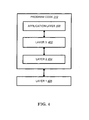
- FIG. 4 is a simplified block diagram of the program code 312 shown in FIG. 3 in accordance with one embodiment of the invention.
- the program code 312 includes an application layer 400, a Layer 3 portion 402, and a Layer 2 portion 404, and is coupled to a Layer 1 portion 406.
- the Layer 3 portion 402 generally performs radio resource control.
- the Layer 2 portion 404 generally performs link control.
- the Layer 1 portion 406 generally performs physical connections.
- 3GPP document R2-112817 proposes two alternatives to move the enhancements forward, including:
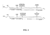
- FIG. 5 illustrates the two alternatives (505 and 510).
- Alt1 when there is data transmission ongoing, the UE is configured by eNB with normal DRX configuration. After the last data transmission is finished and some conditions are reached (e.g., when there is no more data transmission for a predefined period of time), the UE is reconfigured by eNB with configurations which are low power consumption. If new data to be transmitted arrives, the UE is reconfigured with normal DRX configuration. So, power saving is achieved by switching between different configurations.
- Alt2 when there is data transmission ongoing, the UE is configured by eNB with normal DRX configuration.
- the UE After the last data transmission is finished and some conditions are reached (e.g., when there is no more data transmission for a predefined period of time), the UE is requested by eNB to enter RRC_Idle mode. If new data to be transmitted arrives, the UE would attempt to enter RRC_Connected mode to transmit data. After entering RRC_Connected mode, the UE is configured with normal DRX configuration. So, power saving is achieved by RRC state switching between different RRC modes.
- eNB evolved Node B
- eNB could configure UE to RRC_Connected mode.
- eNB has the full knowledge to control the state transition or DRX configuration with respect to DL transmission.
- BSR Buffer Status Report
- the BSR is generally used to indicate the amount of buffered data available for transmission per logical channel group and the details of the BSR can be found in TS 36.321 V10.1.0.
- the possible enhancement proposed in 3GPP document R2-112037 is some kind of UE-assisted mechanism to provide extra information of UL transmission. For example, if UE can send an indication of end of UL transmission, eNB could configure longer DRX cycle for power saving.
- 3GPP document R2-105477 proposes defining one UL message (e.g., UEPowerSavingRequest ) for UE to indicate to the network that it wants to move to power saving mode, (such as, when UE knows that it does not expect UL data in the near future).
- UEPowerSavingRequest e.g., UEPowerSavingRequest
- eNB could release the RRC connection of UE, reconfigure the UE, or do nothing.
- details about DRX could be found in 3GPP TS 36.321 V10.1.0; and details of RRC state transition could be found in TS 36.331 V10.1.0.
- eNB decides to keep a UE in RRC_CONNECTED, it is assumed that eNB would reconfigure the UE with different configurations (such as, DRX, CQI, SRS, measurement, or etc.), depending on whether there is activity (for example, data transmission) from the always-on service(s) in the UE to save UE power and radio resources.
- eNB When an always-on service starts activating (for example, an e-mail application checks the new e-mail), eNB would know there is UL data pending in the UE by BSR, as discussed in 3GPP TS 36.321 V10.1.0. However, the information from the BSR may not be enough for eNB to reconfigure the UE with optimal configurations for the service because BSR could only indicate that there is data available for transmission per logical channel group. Furthermore, eNB may not know exactly which service has activity in the beginning, especially when there are multiple always-on services running in parallel. Under these circumstances, UE may end up with non-optimal configurations and/or may need to be reconfigured again.
- different services may have different characteristics (such as traffic periodicity, volume of traffic, required QoS, or etc.).
- traffic periodicity As an example discussed in 3GPP TS 23.203 V11.1.0, although voice, live streaming video, and interactive game have the same QCI (QoS Class Identifier), it is likely that their traffic pattern would not be the same. Non-optimal configurations may result in poor performance of service or unnecessary UE power consumption.
- a UE could provide data-availability information to eNB about whether or not there is data available for transmission (or there will be activity) per radio bearer, logical channel, or service.
- the data-availability information is not related to how much data per radio bearer, logical channel, or service would be available for transmission.
- the data-availability information could be carried by a RRC message or a MAC Control Element.
- the data-availability information could also be a 1-bit indication or an identifier for a radio bearer, logical channel, or service.
- FIG. 6 illustrates a flow chart 600 in accordance with one exemplary embodiment.
- the UE provides data-availability information to eNB to indicate whether there is buffered data or no buffered data for transmission for a radio bearer.
- the data-availability information could indicate whether there is buffered data or no buffered data for transmission for a logical channel or a service.
- the eNB receives the provided information.
- the eNB reconfigures the UE upon receipt of the provided information.
- the data-availability information could include one (1) bit to indicate whether there is buffered data or no buffered data for transmission for a radio bearer (or a logical channel or a service).
- the data-availability information could also be a bitmap in which each bit of the bitmap indicates whether or not there is data for transmission for a particular radio bearer, logical channel, or service.
- the data-availability information could include an identifier for the radio bearer, logical channel, or service that has buffered data or that has or will have activity (e.g., UL or DL transmission between the UE and the eNB).
- the data-availability information could be carried by a RRC message or a MAC Element.
- the UE could trigger a transmission of the data-availability information when a BSR is triggered.
- the UE could trigger a transmission of the data-availability information when the radio bearer goes from having buffered data to having no buffered data to transmit, or from having no buffered data to having buffered to transmit.
- the UE could also trigger a transmission of the data-availability information when the radio bearer, the logical channel, or the service goes from having activities to having no activities, or from having no activity to having activities.
- the UE 300 includes a program code 312 stored in memory 310.
- the CPU 308 could execute the program code 312 to provide, from the UE, data-availability information to an eNB to indicate whether there is buffered data or no buffered for a radio bearer, a logical channel, or a service to transmit.
- the CPU 308 can execute the program code 312 to perform all of the above-described actions and steps or others described herein.
- RRC_CONNECTED e.g., Alt1 shown in FIG. 5 and discussed in 3GPP document R2-112817
- RRC connection of UE e.g., Alt2 in shown in FIG. 5 and discussed in 3GPP document R2-112817
- RRC connection of UE it would require more exchanged signaling (e.g., for connection establishment, security activation, and etc.), and longer latency to resume transmission when an always-on service starts activating again.
- eNB Since eNB decides whether to keep the UE in RRC_CONNECTED (which has more power consumption and less latency) or release the RRC connection of the UE (which has less power consumption and more latency), it would be better for the UE to provide some specific UE assistance information to help eNB make the decision (e.g., power consumption vs. latency).
- some specific UE assistance information e.g., power consumption vs. latency.
- the UE handovers to another cell it would be difficult for the eNB of the new cell to learn how to select and set up suitable configuration without some assistance from the old cell.
- the UE could send, report, or provide some specific UE-assistance information to the eNB in order to facilitate or enable the eNB to make certain decisions, such as deciding the power saving choice (as shown, for example, in Alt. 1 or Alt. 2 of FIG. 5 and discussed in 3GPP document R2-112817).
- the UE would send, report, or provide the specific UE-assistance information to the eNB at a particular or selected timing, such as at the end of a UL transmission, at the end of a UL transmission of a service, in a RRC connection establishment procedure, in a handover procedure, or in a RRC connection re-establishment procedure.
- the content of the specific UE-assistance information could vary, such as the remaining power of the UE, the UE preference about the power saving configuration, or the duration of the UE stayed in RRC_Idle last time.
- the specific UE-related information could be sent, reported, or provided from a source eNB to a target eNB in a handover preparation procedure (for example, in a Handover Request message) to enable the target eNB to decide or select the suitable configuration (e.g., DRX configuration) for the UE with consideration for diverse data applications.
- the specific UE-related information could be multiple sets of UE configurations (such as configurations for DRX, CQI, SRS, measurement, or etc.), time information (such as inter packet transmission time of a service or the time interval between the transmissions of specific messages from the UE), or the period the UE uses a specific configuration.
- FIG. 7 illustrates a flow chart 700 in accordance with one exemplary embodiment.
- the UE sends, provides, or reports specific UE-assistance information to the eNB at certain timing.
- the specific UE-assistance information could be related to remaining batter power of the UE, or the UE's preference about the power saving configuration (such as enter idle mode or enter long DRX in connected mode).
- the specific UE-assistance information could be provided in the end of a UL transmission or in the end of a UL transmission of a service.
- the specific UE assistance information could also be carried by a RRC message, or provided in a RRC connection establishment procedure (such as a RRC Connection Request message or a RRC Connection Setup Complete message), a RRC connection re-establishment procedure (such as a RRC Connection Reestablishment Request message or a RRC Connection Reestablishment Complete message), or a handover procedure (such as a RRC Connection Reconfiguration Complete message).
- the specific UE-assistance information could be carried by a RRC Connection Release Request message used to request the eNB to release the RRC Connection for the UE, or by a RRC Power Saving Request message used to request the eNB to change the configuration of the UE to save the power.
- a RRC Connection Release Request message used to request the eNB to release the RRC Connection for the UE
- a RRC Power Saving Request message used to request the eNB to change the configuration of the UE to save the power.
- the eNB receives the specific UE-assistance information.
- the eNB makes certain decision based on the received specific UE-assistance information, such as deciding the power saving choice (as shown, for example, in Alt. 1 or Alt. 2 of FIG. 5 and discussed in 3GPP document R2-112817).
- the UE 300 includes a program code 312 stored in memory 310.
- the CPU 308 could execute the program code 312 to send specific UE-assistance information from a UE (user equipment) to an eNB (evolved Node B) at a particular timing.
- the CPU 308 can execute the program code 312 to perform all of the above-described actions and steps or others described herein.
- FIG. 8 illustrates a flow chart 800 in accordance with one exemplary embodiment.
- the source eNB sends or provides more than one UE configuration sets to the target eNB during handover preparation.
- the UE configuration sets could include configuration for DRX (discontinuous reception), CQI (channel quality indicator), and/or SRS (sounding reference symbol).
- the UE configuration sets could be carried in a Handover Request message.
- the target eNB receives the UE configuration sets.
- the target eNB determines a suitable configuration (for example, the DRX configuration) for the UE, which is typically configured with one set of configuration at a time.
- a source eNB 300 includes a program code 312 stored in memory 310.
- the CPU 308 could execute the program code 312 to send specific UE-related information from a source eNB (evolved Node B) to a target eNB during handover preparation.
- the CPU 308 can execute the program code 312 to perform all of the above-described actions and steps or others described herein.
- concurrent channels may be established based on pulse repetition frequencies.
- concurrent channels may be established based on pulse position or offsets.
- concurrent channels may be established based on time hopping sequences.
- concurrent channels may be established based on pulse repetition frequencies, pulse positions or offsets, and time hopping sequences.
- the various illustrative logical blocks, modules, and circuits described in connection with the aspects disclosed herein may be implemented within or performed by an integrated circuit ("IC"), an access terminal, or an access point.
- the IC may comprise a general purpose processor, a digital signal processor (DSP), an application specific integrated circuit (ASIC), a field programmable gate array (FPGA) or other programmable logic device, discrete gate or transistor logic, discrete hardware components, electrical components, optical components, mechanical components, or any combination thereof designed to perform the functions described herein, and may execute codes or instructions that reside within the IC, outside of the IC, or both.
- a general purpose processor may be a microprocessor, but in the alternative, the processor may be any conventional processor, controller, microcontroller, or state machine.
- a processor may also be implemented as a combination of computing devices, e.g., a combination of a DSP and a microprocessor, a plurality of microprocessors, one or more microprocessors in conjunction with a DSP core, or any other such configuration.
- a software module e.g., including executable instructions and related data
- other data may reside in a data memory such as RAM memory, flash memory, ROM memory, EPROM memory, EEPROM memory, registers, a hard disk, a removable disk, a CD-ROM, or any other form of computer-readable storage medium known in the art.
- a sample storage medium may be coupled to a machine such as, for example, a computer/processor (which may be referred to herein, for convenience, as a "processor") such the processor can read information (e.g., code) from and write information to the storage medium.
- a sample storage medium may be integral to the processor.
- the processor and the storage medium may reside in an ASIC.
- the ASIC may reside in user equipment.
- the processor and the storage medium may reside as discrete components in user equipment.
- any suitable computer-program product may comprise a computer-readable medium comprising codes relating to one or more of the aspects of the disclosure.
- a computer program product may comprise packaging materials.
Landscapes
- Engineering & Computer Science (AREA)
- Computer Networks & Wireless Communication (AREA)
- Signal Processing (AREA)
- Mobile Radio Communication Systems (AREA)
Abstract
Description
- The present Application claims the benefit of
U.S. Provisional Patent Application Serial No. 61/497,263 filed on June 15, 2011 - This disclosure generally relates to wireless communication networks, and more particularly, to a method and apparatus to provide assistance information for reconfiguration in a wireless communication system.
- With the rapid rise in demand for communication of large amounts of data to and from mobile communication devices, traditional mobile voice communication networks are evolving into networks that communicate with Internet Protocol (IP) data packets. Such IP data packet communication can provide users of mobile communication devices with voice over IP, multimedia, multicast and on-demand communication services.
- An exemplary network structure for which standardization is currently taking place is an Evolved Universal Terrestrial Radio Access Network (E-UTRAN). The E-UTRAN system can provide high data throughput in order to realize the above-noted voice over IP and multimedia services. The E-UTRAN system's standardization work is currently being performed by the 3GPP standards organization. Accordingly, changes to the current body of 3GPP standard are currently being submitted and considered to evolve and finalize the 3GPP standard.
- A method and apparatus are disclosed to provide assistance information for reconfiguration in a wireless communication system. In one embodiment, the method comprises providing, from a UE (user equipment), information to an eNB (evolved Node B) to indicate whether there is buffered data or no buffered data for a radio bearer, a logical channel, or a service.
-
FIG. 1 shows a diagram of a wireless communication system according to one exemplary embodiment. -
FIG. 2 is a block diagram of a transmitter system (also known as access network) and a receiver system (also known as user equipment or UE) according to one exemplary embodiment. -
FIG. 3 is a functional block diagram of a communication system according to one exemplary embodiment. -
FIG. 4 is a functional block diagram of the program code ofFIG. 3 according to one exemplary embodiment. -
FIG. 5 is a chart according to one exemplary embodiment. -
FIG. 6 illustrates a flow chart in accordance with one exemplary embodiment. -
FIG. 7 shows a flow chart in accordance with one exemplary embodiment. -
FIG. 8 is a flow chart in accordance with one exemplary embodiment. - The exemplary wireless communication systems and devices described below employ a wireless communication system, supporting a broadcast service. Wireless communication systems are widely deployed to provide various types of communication such as voice, data, and so on. These systems may be based on code division multiple access (CDMA), time division multiple access (TDMA), orthogonal frequency division multiple access (OFDMA), 3GPP LTE (Long Term Evolution) wireless access, 3GPP LTE-A or LTE-Advanced (Long Term Evolution Advanced), 3GPP2 UMB (Ultra Mobile Broadband), WiMax, or some other modulation techniques.
- In particular, the exemplary wireless communication systems devices described below may be designed to support one or more standards such as the standard offered by a consortium named "3rd Generation Partnership Project" referred to herein as 3GPP, including Document Nos. RP-110454, "LTE RAN Enhancements for Diverse Data Applications"; R2-112817, "Considerations for Evaluation Methods and Simulation Modeling"; R2-112037, "Discussion on Management of Diverse Data Applications"; R2-105477, "UE power saving and fast dormancy in LTE network"; TS 36.321 V10.1.0, "MAC protocol specification (Release 10)"; TS 36.331 V10.1.0, "RRC protocol specification (Release 10)"; and TS 23.203 V11.1.0, "Policy and charging control architecture (Release 11)". The standards and documents listed above are hereby expressly incorporated herein.
-
FIG. 1 shows a multiple access wireless communication system according to one embodiment of the invention. An access network 100 (AN) includes multiple antenna groups, one including 104 and 106, another including 108 and 110, and an additional including 112 and 114. InFIG. 1 , only two antennas are shown for each antenna group, however, more or fewer antennas may be utilized for each antenna group. Access terminal 116 (AT) is in communication withantennas antennas terminal 116 overforward link 120 and receive information fromaccess terminal 116 overreverse link 118. Access terminal (AT) 122 is in communication withantennas antennas forward link 126 and receive information from access terminal (AT) 122 overreverse link 124. In a FDD system,communication links forward link 120 may use a different frequency then that used byreverse link 118. - Each group of antennas and/or the area in which they are designed to communicate is often referred to as a sector of the access network. In the embodiment, antenna groups each are designed to communicate to access terminals in a sector of the areas covered by
access network 100. - In communication over
forward links access network 100 may utilize beamforming in order to improve the signal-to-noise ratio of forward links for thedifferent access terminals - An access network (AN) may be a fixed station or base station used for communicating with the terminals and may also be referred to as an access point, a Node B, a base station, an enhanced base station, an eNodeB, or some other terminology. An access terminal (AT) may also be called user equipment (UE), a wireless communication device, terminal, access terminal or some other terminology.
-
FIG. 2 is a simplified block diagram of an embodiment of a transmitter system 210 (also known as the access network) and a receiver system 250 (also known as access terminal (AT) or user equipment (UE)) in aMIMO system 200. At thetransmitter system 210, traffic data for a number of data streams is provided from adata source 212 to a transmit (TX)data processor 214. - In one embodiment, each data stream is transmitted over a respective transmit antenna. TX
data processor 214 formats, codes, and interleaves the traffic data for each data stream based on a particular coding scheme selected for that data stream to provide coded data. - The coded data for each data stream may be multiplexed with pilot data using OFDM techniques. The pilot data is typically a known data pattern that is processed in a known manner and may be used at the receiver system to estimate the channel response. The multiplexed pilot and coded data for each data stream is then modulated (i.e., symbol mapped) based on a particular modulation scheme (e.g., BPSK, QPSK, M-PSK, or M-QAM) selected for that data stream to provide modulation symbols. The data rate, coding, and modulation for each data stream may be determined by instructions performed by
processor 230. - The modulation symbols for all data streams are then provided to a
TX MIMO processor 220, which may further process the modulation symbols (e.g., for OFDM). TX MIMOprocessor 220 then provides NT modulation symbol streams to NT transmitters (TMTR) 222a through 222t. In certain embodiments, TXMIMO processor 220 applies beamforming weights to the symbols of the data streams and to the antenna from which the symbol is being transmitted. - Each transmitter 222 receives and processes a respective symbol stream to provide one or more analog signals, and further conditions (e.g., amplifies, filters, and upconverts) the analog signals to provide a modulated signal suitable for transmission over the MIMO channel. NT modulated signals from
transmitters 222a through 222t are then transmitted from NT antennas 224a through 224t, respectively. - At
receiver system 250, the transmitted modulated signals are received by NR antennas 252a through 252r and the received signal from each antenna 252 is provided to a respective receiver (RCVR) 254a through 254r. Each receiver 254 conditions (e.g., filters, amplifies, and downconverts) a respective received signal, digitizes the conditioned signal to provide samples, and further processes the samples to provide a corresponding "received" symbol stream. - An RX
data processor 260 then receives and processes the NR received symbol streams from NR receivers 254 based on a particular receiver processing technique to provide NT "detected" symbol streams. The RXdata processor 260 then demodulates, deinterleaves, and decodes each detected symbol stream to recover the traffic data for the data stream. The processing by RXdata processor 260 is complementary to that performed by TX MIMOprocessor 220 and TXdata processor 214 attransmitter system 210. - A
processor 270 periodically determines which pre-coding matrix to use (discussed below).Processor 270 formulates a reverse link message comprising a matrix index portion and a rank value portion. - The reverse link message may comprise various types of information regarding the communication link and/or the received data stream. The reverse link message is then processed by a TX
data processor 238, which also receives traffic data for a number of data streams from adata source 236, modulated by amodulator 280, conditioned bytransmitters 254a through 254r, and transmitted back totransmitter system 210. - At
transmitter system 210, the modulated signals fromreceiver system 250 are received by antennas 224, conditioned by receivers 222, demodulated by ademodulator 240, and processed by aRX data processor 242 to extract the reserve link message transmitted by thereceiver system 250.Processor 230 then determines which pre-coding matrix to use for determining the beamforming weights then processes the extracted message. - Turning to
FIG. 3 , this figure shows an alternative simplified functional block diagram of a communication device according to one embodiment of the invention. As shown inFIG. 3 , thecommunication device 300 in a wireless communication system can be utilized for realizing the UEs (or ATs) 116 and 122 inFIG. 1 , or for realizing the eNB (or base station) 100 inFIG. 1 , and the wireless communications system is preferably the LTE system. Thecommunication device 300 may include aninput device 302, anoutput device 304, acontrol circuit 306, a central processing unit (CPU) 308, amemory 310, aprogram code 312, and atransceiver 314. Thecontrol circuit 306 executes theprogram code 312 in thememory 310 through theCPU 308, thereby controlling an operation of thecommunications device 300. Thecommunications device 300 can receive signals input by a user through theinput device 302, such as a keyboard or keypad, and can output images and sounds through theoutput device 304, such as a monitor or speakers. Thetransceiver 314 is used to receive and transmit wireless signals, delivering received signals to thecontrol circuit 306, and outputting signals generated by thecontrol circuit 306 wirelessly. -
FIG. 4 is a simplified block diagram of theprogram code 312 shown inFIG. 3 in accordance with one embodiment of the invention. In this embodiment, theprogram code 312 includes anapplication layer 400, aLayer 3portion 402, and aLayer 2portion 404, and is coupled to aLayer 1portion 406. TheLayer 3portion 402 generally performs radio resource control. TheLayer 2portion 404 generally performs link control. TheLayer 1portion 406 generally performs physical connections. - The range of device types utilizing current mobile networks continues to expand, encompassing, as examples, smartphones, laptops, netbooks, tablets, and embedded modems. Many are capable of running a wide variety of data applications, often in parallel. Numerous applications require that an always-on mobile-broadband experience is seamlessly delivered and presented to the end user. When attempting to provide such always-on connectivity at the RAN level, trade-offs are often encountered between UE power consumption, user experience, data transfer latency, network efficiency and control plane signaling overhead.
- Therefore, per 3GPP document RP-110454, the work item "Enhancements for diverse data applications" for LTE release I 1 is under discussion to generate the necessary improvements. In general, RRC (Radio Resource Control) state control mechanisms and DRX (Discontinuous Reception) configurations may be optimized with particular applications in mind but these may not remain optimal as different applications are installed/started/stopped on the device and as the consequent traffic profile of the device changes over time.
- Under this work item, enhancements in the following areas would be considered:
- Enhancements, within existing RRC states, to RRC state-control mechanisms and RRM (Radio Resource Management) mechanisms that offer system efficiency improvements and/or reduced UE power consumption for devices exhibiting a continued but intermittent data activity.
- Enhancements to DRX configuration/control mechanisms to be more responsive to the needs and activity of either single or multiple applications running in parallel, with improved adaptability to time-varying traffic profiles and to application requirements, thereby allowing for an improved optimization of the trade-off between performance and UE-battery-consumption.
- Efficient management of system resources (e.g. UL control channel resources) for connected mode UEs that are temporarily inactive, facilitating potentially larger user populations in connected mode.
- For the above enhancements, knowledge from both the UE and the network should be considered where possible.
- 3GPP document R2-112817 proposes two alternatives to move the enhancements forward, including:
- Alternative 1 (Alt1) - Efficient configurations for long-lived RRC_Connected mode.
- Alternative 1 (Alt2) - Optimal mechanisms for state transitions between RRC_Idle mode and RRC_Connected mode.
-
FIG. 5 illustrates the two alternatives (505 and 510). In Alt1 (505), when there is data transmission ongoing, the UE is configured by eNB with normal DRX configuration. After the last data transmission is finished and some conditions are reached (e.g., when there is no more data transmission for a predefined period of time), the UE is reconfigured by eNB with configurations which are low power consumption. If new data to be transmitted arrives, the UE is reconfigured with normal DRX configuration. So, power saving is achieved by switching between different configurations. In Alt2 (510), when there is data transmission ongoing, the UE is configured by eNB with normal DRX configuration. After the last data transmission is finished and some conditions are reached (e.g., when there is no more data transmission for a predefined period of time), the UE is requested by eNB to enter RRC_Idle mode. If new data to be transmitted arrives, the UE would attempt to enter RRC_Connected mode to transmit data. After entering RRC_Connected mode, the UE is configured with normal DRX configuration. So, power saving is achieved by RRC state switching between different RRC modes. - It is further discussed in 3GPP document R2-112037 that if there is no DL (downlink) traffic, eNB (evolved Node B) could configure UE to RRC_Connected mode. In general, eNB has the full knowledge to control the state transition or DRX configuration with respect to DL transmission. However, for UL (uplink) transmission, eNB would only know the transmission requirement from BSR (Buffer Status Report). The BSR is generally used to indicate the amount of buffered data available for transmission per logical channel group and the details of the BSR can be found in TS 36.321 V10.1.0. In general, the possible enhancement proposed in 3GPP document R2-112037 is some kind of UE-assisted mechanism to provide extra information of UL transmission. For example, if UE can send an indication of end of UL transmission, eNB could configure longer DRX cycle for power saving.
- Furthermore, 3GPP document R2-105477 proposes defining one UL message (e.g., UEPowerSavingRequest) for UE to indicate to the network that it wants to move to power saving mode, (such as, when UE knows that it does not expect UL data in the near future). Once eNB receives the message, eNB could release the RRC connection of UE, reconfigure the UE, or do nothing. In addition, details about DRX could be found in 3GPP TS 36.321 V10.1.0; and details of RRC state transition could be found in TS 36.331 V10.1.0.
- If eNB decides to keep a UE in RRC_CONNECTED, it is assumed that eNB would reconfigure the UE with different configurations (such as, DRX, CQI, SRS, measurement, or etc.), depending on whether there is activity (for example, data transmission) from the always-on service(s) in the UE to save UE power and radio resources.
- When an always-on service starts activating (for example, an e-mail application checks the new e-mail), eNB would know there is UL data pending in the UE by BSR, as discussed in 3GPP TS 36.321 V10.1.0. However, the information from the BSR may not be enough for eNB to reconfigure the UE with optimal configurations for the service because BSR could only indicate that there is data available for transmission per logical channel group. Furthermore, eNB may not know exactly which service has activity in the beginning, especially when there are multiple always-on services running in parallel. Under these circumstances, UE may end up with non-optimal configurations and/or may need to be reconfigured again.
- Also, different services may have different characteristics (such as traffic periodicity, volume of traffic, required QoS, or etc.). As an example discussed in 3GPP TS 23.203 V11.1.0, although voice, live streaming video, and interactive game have the same QCI (QoS Class Identifier), it is likely that their traffic pattern would not be the same. Non-optimal configurations may result in poor performance of service or unnecessary UE power consumption.
- In general, to let eNB know exactly which service has activity, a UE could provide data-availability information to eNB about whether or not there is data available for transmission (or there will be activity) per radio bearer, logical channel, or service. In this embodiment, the data-availability information is not related to how much data per radio bearer, logical channel, or service would be available for transmission. The data-availability information could be carried by a RRC message or a MAC Control Element. The data-availability information could also be a 1-bit indication or an identifier for a radio bearer, logical channel, or service. When eNB receives the information, eNB could reconfigure the UE with optimal configuration corresponding to the service having activity (such as having data for transmission).
-
FIG. 6 illustrates aflow chart 600 in accordance with one exemplary embodiment. Instep 605, the UE provides data-availability information to eNB to indicate whether there is buffered data or no buffered data for transmission for a radio bearer. In one embodiment, the data-availability information could indicate whether there is buffered data or no buffered data for transmission for a logical channel or a service. Instep 610, the eNB receives the provided information. Instep 615, the eNB reconfigures the UE upon receipt of the provided information. In one embodiment, the data-availability information could include one (1) bit to indicate whether there is buffered data or no buffered data for transmission for a radio bearer (or a logical channel or a service). The data-availability information could also be a bitmap in which each bit of the bitmap indicates whether or not there is data for transmission for a particular radio bearer, logical channel, or service. Furthermore, the data-availability information could include an identifier for the radio bearer, logical channel, or service that has buffered data or that has or will have activity (e.g., UL or DL transmission between the UE and the eNB). - In one embodiment, the data-availability information could be carried by a RRC message or a MAC Element. Furthermore, the UE could trigger a transmission of the data-availability information when a BSR is triggered. Alternatively, the UE could trigger a transmission of the data-availability information when the radio bearer goes from having buffered data to having no buffered data to transmit, or from having no buffered data to having buffered to transmit. The UE could also trigger a transmission of the data-availability information when the radio bearer, the logical channel, or the service goes from having activities to having no activities, or from having no activity to having activities.
- Referring back to
FIGS. 3 and4 , theUE 300 includes aprogram code 312 stored inmemory 310. In one embodiment, theCPU 308 could execute theprogram code 312 to provide, from the UE, data-availability information to an eNB to indicate whether there is buffered data or no buffered for a radio bearer, a logical channel, or a service to transmit. In addition, theCPU 308 can execute theprogram code 312 to perform all of the above-described actions and steps or others described herein. - In addition, keeping a UE in RRC_CONNECTED (e.g., Alt1 shown in
FIG. 5 and discussed in 3GPP document R2-112817) would likely consume more UE power compared to release RRC connection of UE (e.g., Alt2 in shown inFIG. 5 and discussed in 3GPP document R2-112817). However, if RRC connection of UE is released, it would require more exchanged signaling (e.g., for connection establishment, security activation, and etc.), and longer latency to resume transmission when an always-on service starts activating again. Since eNB decides whether to keep the UE in RRC_CONNECTED (which has more power consumption and less latency) or release the RRC connection of the UE (which has less power consumption and more latency), it would be better for the UE to provide some specific UE assistance information to help eNB make the decision (e.g., power consumption vs. latency). On the other hand, from the network point of view, if the UE handovers to another cell, it would be difficult for the eNB of the new cell to learn how to select and set up suitable configuration without some assistance from the old cell. - In general, the UE could send, report, or provide some specific UE-assistance information to the eNB in order to facilitate or enable the eNB to make certain decisions, such as deciding the power saving choice (as shown, for example, in Alt. 1 or Alt. 2 of
FIG. 5 and discussed in 3GPP document R2-112817). In one embodiment, the UE would send, report, or provide the specific UE-assistance information to the eNB at a particular or selected timing, such as at the end of a UL transmission, at the end of a UL transmission of a service, in a RRC connection establishment procedure, in a handover procedure, or in a RRC connection re-establishment procedure. Furthermore, the content of the specific UE-assistance information could vary, such as the remaining power of the UE, the UE preference about the power saving configuration, or the duration of the UE stayed in RRC_Idle last time. In another embodiment, the specific UE-related information could be sent, reported, or provided from a source eNB to a target eNB in a handover preparation procedure (for example, in a Handover Request message) to enable the target eNB to decide or select the suitable configuration (e.g., DRX configuration) for the UE with consideration for diverse data applications. The specific UE-related information could be multiple sets of UE configurations (such as configurations for DRX, CQI, SRS, measurement, or etc.), time information (such as inter packet transmission time of a service or the time interval between the transmissions of specific messages from the UE), or the period the UE uses a specific configuration. -
FIG. 7 illustrates aflow chart 700 in accordance with one exemplary embodiment. Instep 705, the UE sends, provides, or reports specific UE-assistance information to the eNB at certain timing. In one embodiment, the specific UE-assistance information could be related to remaining batter power of the UE, or the UE's preference about the power saving configuration (such as enter idle mode or enter long DRX in connected mode). Furthermore, the specific UE-assistance information could be provided in the end of a UL transmission or in the end of a UL transmission of a service. The specific UE assistance information could also be carried by a RRC message, or provided in a RRC connection establishment procedure (such as a RRC Connection Request message or a RRC Connection Setup Complete message), a RRC connection re-establishment procedure (such as a RRC Connection Reestablishment Request message or a RRC Connection Reestablishment Complete message), or a handover procedure (such as a RRC Connection Reconfiguration Complete message). In one embodiment the specific UE-assistance information could be carried by a RRC Connection Release Request message used to request the eNB to release the RRC Connection for the UE, or by a RRC Power Saving Request message used to request the eNB to change the configuration of the UE to save the power. Instep 710 ofFIG. 7 , the eNB receives the specific UE-assistance information. Instep 715, the eNB makes certain decision based on the received specific UE-assistance information, such as deciding the power saving choice (as shown, for example, in Alt. 1 or Alt. 2 ofFIG. 5 and discussed in 3GPP document R2-112817). - Referring back to
FIGS. 3 and4 , theUE 300 includes aprogram code 312 stored inmemory 310. In one embodiment, theCPU 308 could execute theprogram code 312 to send specific UE-assistance information from a UE (user equipment) to an eNB (evolved Node B) at a particular timing. In addition, theCPU 308 can execute theprogram code 312 to perform all of the above-described actions and steps or others described herein. -
FIG. 8 illustrates aflow chart 800 in accordance with one exemplary embodiment. Instep 805, the source eNB sends or provides more than one UE configuration sets to the target eNB during handover preparation. In one embodiment, the UE configuration sets could include configuration for DRX (discontinuous reception), CQI (channel quality indicator), and/or SRS (sounding reference symbol). Furthermore, the UE configuration sets could be carried in a Handover Request message. Instep 810, the target eNB receives the UE configuration sets. Instep 815, the target eNB determines a suitable configuration (for example, the DRX configuration) for the UE, which is typically configured with one set of configuration at a time. - Referring back to
FIGS. 3 and4 , asource eNB 300 includes aprogram code 312 stored inmemory 310. In one embodiment, theCPU 308 could execute theprogram code 312 to send specific UE-related information from a source eNB (evolved Node B) to a target eNB during handover preparation. In addition, theCPU 308 can execute theprogram code 312 to perform all of the above-described actions and steps or others described herein. - Various aspects of the disclosure have been described above. It should be apparent that the teachings herein may be embodied in a wide variety of forms and that any specific structure, function, or both being disclosed herein is merely representative. Based on the teachings herein one skilled in the art should appreciate that an aspect disclosed herein may be implemented independently of any other aspects and that two or more of these aspects may be combined in various ways. For example, an apparatus may be implemented or a method may be practiced using any number of the aspects set forth herein. In addition, such an apparatus may be implemented or such a method may be practiced using other structure, functionality, or structure and functionality in addition to or other than one or more of the aspects set forth herein. As an example of some of the above concepts, in some aspects concurrent channels may be established based on pulse repetition frequencies. In some aspects concurrent channels may be established based on pulse position or offsets. In some aspects concurrent channels may be established based on time hopping sequences. In some aspects concurrent channels may be established based on pulse repetition frequencies, pulse positions or offsets, and time hopping sequences.
- Those of skill in the art would understand that information and signals may be represented using any of a variety of different technologies and techniques. For example, data, instructions, commands, information, signals, bits, symbols, and chips that may be referenced throughout the above description may be represented by voltages, currents, electromagnetic waves, magnetic fields or particles, optical fields or particles, or any combination thereof.
- Those of skill would further appreciate that the various illustrative logical blocks, modules, processors, means, circuits, and algorithm steps described in connection with the aspects disclosed herein may be implemented as electronic hardware (e.g., a digital implementation, an analog implementation, or a combination of the two, which may be designed using source coding or some other technique), various forms of program or design code incorporating instructions (which may be referred to herein, for convenience, as "software" or a "software module"), or combinations of both. To clearly illustrate this interchangeability of hardware and software, various illustrative components, blocks, modules, circuits, and steps have been described above generally in terms of their functionality. Whether such functionality is implemented as hardware or software depends upon the particular application and design constraints imposed on the overall system. Skilled artisans may implement the described functionality in varying ways for each particular application, but such implementation decisions should not be interpreted as causing a departure from the scope of the present disclosure.
- In addition, the various illustrative logical blocks, modules, and circuits described in connection with the aspects disclosed herein may be implemented within or performed by an integrated circuit ("IC"), an access terminal, or an access point. The IC may comprise a general purpose processor, a digital signal processor (DSP), an application specific integrated circuit (ASIC), a field programmable gate array (FPGA) or other programmable logic device, discrete gate or transistor logic, discrete hardware components, electrical components, optical components, mechanical components, or any combination thereof designed to perform the functions described herein, and may execute codes or instructions that reside within the IC, outside of the IC, or both. A general purpose processor may be a microprocessor, but in the alternative, the processor may be any conventional processor, controller, microcontroller, or state machine. A processor may also be implemented as a combination of computing devices, e.g., a combination of a DSP and a microprocessor, a plurality of microprocessors, one or more microprocessors in conjunction with a DSP core, or any other such configuration.
- It is understood that any specific order or hierarchy of steps in any disclosed process is an example of a sample approach. Based upon design preferences, it is understood that the specific order or hierarchy of steps in the processes may be rearranged while remaining within the scope of the present disclosure. The accompanying method claims present elements of the various steps in a sample order, and are not meant to be limited to the specific order or hierarchy presented.
- The steps of a method or algorithm described in connection with the aspects disclosed herein may be embodied directly in hardware, in a software module executed by a processor, or in a combination of the two. A software module (e.g., including executable instructions and related data) and other data may reside in a data memory such as RAM memory, flash memory, ROM memory, EPROM memory, EEPROM memory, registers, a hard disk, a removable disk, a CD-ROM, or any other form of computer-readable storage medium known in the art. A sample storage medium may be coupled to a machine such as, for example, a computer/processor (which may be referred to herein, for convenience, as a "processor") such the processor can read information (e.g., code) from and write information to the storage medium. A sample storage medium may be integral to the processor. The processor and the storage medium may reside in an ASIC. The ASIC may reside in user equipment. In the alternative, the processor and the storage medium may reside as discrete components in user equipment. Moreover, in some aspects any suitable computer-program product may comprise a computer-readable medium comprising codes relating to one or more of the aspects of the disclosure. In some aspects a computer program product may comprise packaging materials.
- While the invention has been described in connection with various aspects, it will be understood that the invention is capable of further modifications. This application is intended to cover any variations, uses or adaptation of the invention following, in general, the principles of the invention, and including such departures from the present disclosure as come within the known and customary practice within the art to which the invention pertains.
- For the sake of completeness, the invention is described by way of the following clauses, wherein the
independent clauses 1 and/or 5 and/or 9 and/or 11 and/or their dependent claims may be combined and the processor of the communication device of clause 17 may be configured to execute a program code stored in memory for providing assistance information for reconfiguration by the method steps as defined in such a combined clause: - 1. A method to provide assistance information for reconfiguration, comprising:
- providing, from a UE (user equipment), information to an eNB (evolved Node B) to indicate whether there is buffered data or no buffered data for a radio bearer, a logical channel, or a service.
- 2. The method of
clause 1, wherein the information includes one (1) bit to indicate whether there is buffered data or no buffered data for a corresponding radio bearer, logical channel, or service. - 3. The method of
clause - 4. The method of anyone of
clauses 1 to 3, wherein the UE triggers a transmission of the information when the radio bearer goes from having buffered data to having no buffered data or from having no buffered to having buffered data. - 5. A method to provide assistance information for reconfiguration, comprising:
- providing, from a UE (user equipment), information to an eNB (evolved Node B) to indicate whether there will be activity for a radio bearer, a logical channel, or a service.
- 6. The method of clause 5, wherein the information includes an identifier for the radio bearer, logical channel, or service that will have activity.
- 7. The method of clause 5 or 6, wherein the information is carried by a RRC (Radio Resource Control) message or a MAC (Medium Access Control) Element.
- 8. The method of anyone of clauses 5 to 7, wherein the UE triggers a transmission of the information when the radio bearer, the logical channel, or the service goes from having activity to having no activity or from having no activity to having activity.
- 9. A method to provide assistance information for reconfiguration, comprising:
- sending an indication of remaining power of a UE (user equipment) from the UE to an eNB (evolved Node B) at a particular timing.
- 10. The method of clause 9, wherein the particular timing is at the end of a UL (uplink) transmission, at the end of a UL transmission of a service, or during a RRC connection establishment procedure, a RRC connection re-establishment procedure, or a handover procedure.
- 11. A method to provide assistance information for reconfiguration, comprising:
- sending a preference about the power saving configuration of a UE (user equipment) from the UE to an eNB (evolved Node B) at a particular timing.
- 12. The method of clause 11, wherein the particular timing is at the end of a UL (uplink) transmission, at the end of a UL transmission of a service, or during a RRC connection establishment procedure, a RRC connection re-establishment procedure, or a handover procedure.
- 13. The method of clause 11 or 12, wherein the preference indicates that the UE prefers to enter RRC_Idle mode.
- 14. The method of anyone of clauses 11 to 13, wherein the preference indicates that the UE prefers to enter long DRX in RRC_Connected mode.
- 15. The method of anyone of clauses 11 to 14, wherein the preference is carried by a RRC (Radio Resource Control) message.
- 16. The method of clause 15, wherein the RRC message is used to request eNB to change the configuration of the UE to save power.
- 17. A communication device for use in a wireless communication system, the communication device comprising:
- a control circuit;
- a processor installed in the control circuit;
- a memory installed in the control circuit and coupled to the processor;
- 18. A method to provide assistance information for reconfiguration, comprising:
- sending a plurality of UE (user equipment) configuration sets from a first eNB (evolved Node B) to a second eNB during handover preparation.
- 19. The method of clause 18, wherein the UE configuration sets include configuration of DRX (discontinuous reception), CQI (channel quality indicator), and/or SRS (sounding reference symbol).
- 20. The method of clause 18 or 19, wherein the UE configuration sets are carried in a Handover Request message.
- 21. An access network device for use in a wireless communication system, the access network device comprising:
- a control circuit;
- a processor installed in the control circuit;
- a memory installed in the control circuit and coupled to the processor;
Claims (14)
- A method to provide assistance information for reconfiguration, comprising:providing, from a UE (user equipment), information to an eNB (evolved Node B) to indicate whether there is buffered data or no buffered data and/or whether there will be activity for a radio bearer, a logical channel, or a service, and/orsending an indication of remaining power of the UE (user equipment) and/or a preference about the power saving configuration of the UE from the UE to an eNB (evolved Node B) at a particular timing.
- The method of claim 1, wherein the information includes one (1) bit to indicate whether there is buffered data or no buffered data for a corresponding radio bearer, logical channel, or service.
- The method of claim 1 or 2, wherein the UE triggers a transmission of the information when the radio bearer goes from having buffered data to having no buffered data or from having no buffered to having buffered data, and/or wherein the UE triggers a transmission of the information when the radio bearer, the logical channel, or the service goes from having activity to having no activity or from having no activity to having activity.
- The method of anyone of claims 1 to 3, wherein the information includes an identifier for the radio bearer, logical channel, or service that will have activity.
- The method of anyone of claims 1 to 4, wherein the information is carried by a RRC (Radio Resource Control) message or a MAC (Medium Access Control) Element.
- The method of anyone of claims 1 to 5, wherein the particular timing is at the end of a UL (uplink) transmission, at the end of a UL transmission of a service, or during a RRC connection establishment procedure, a RRC connection re-establishment procedure, or a handover procedure.
- The method of anyone of claims 1 to 6, wherein the preference indicates that the UE prefers to enter RRC_Idle mode, and/or wherein the preference indicates that the UE prefers to enter long DRX in RRC_Connected mode.
- The method of anyone of claims 1 to 6, wherein the preference is carried by a RRC (Radio Resource Control) message.
- The method of claim 8, wherein the RRC message is used to request eNB to change the configuration of the UE to save power.
- A communication device for use in a wireless communication system, the communication device comprising:a control circuit;a processor installed in the control circuit;a memory installed in the control circuit and coupled to the processor;wherein the processor is configured to execute a program code stored in memory for providing assistance information for reconfiguration by the method steps as defined in anyone of the preceeding claims.
- A method to provide assistance information for reconfiguration, comprising:sending a plurality of UE (user equipment) configuration sets from a first eNB (evolved Node B) to a second eNB during handover preparation.
- The method of claim 11, wherein the UE configuration sets include configuration of DRX (discontinuous reception), CQI (channel quality indicator), and/or SRS (sounding reference symbol).
- The method of claim 11 or 12, wherein the UE configuration sets are carried in a Handover Request message.
- An access network device for use in a wireless communication system, the access network device comprising:a control circuit;a processor installed in the control circuit;a memory installed in the control circuit and coupled to the processor;wherein the processor is configured to execute a program code stored in memory for providing assistance information for reconfiguration by the method steps as defined in anyone of the preceeding claims 11 to 13.
Applications Claiming Priority (1)
| Application Number | Priority Date | Filing Date | Title |
|---|---|---|---|
| US201161497263P | 2011-06-15 | 2011-06-15 |
Publications (3)
| Publication Number | Publication Date |
|---|---|
| EP2536226A2 true EP2536226A2 (en) | 2012-12-19 |
| EP2536226A3 EP2536226A3 (en) | 2013-03-13 |
| EP2536226B1 EP2536226B1 (en) | 2016-12-14 |
Family
ID=46331005
Family Applications (1)
| Application Number | Title | Priority Date | Filing Date |
|---|---|---|---|
| EP12004523.2A Active EP2536226B1 (en) | 2011-06-15 | 2012-06-15 | Method and apparatus to provide assistance information for reconfiguration in a wireless communication system |
Country Status (3)
| Country | Link |
|---|---|
| US (1) | US8824301B2 (en) |
| EP (1) | EP2536226B1 (en) |
| TW (1) | TWI466567B (en) |
Cited By (2)
| Publication number | Priority date | Publication date | Assignee | Title |
|---|---|---|---|---|
| EP3354063A4 (en) * | 2015-09-23 | 2018-09-26 | Telefonaktiebolaget LM Ericsson (PUBL) | Cooperation between wireless communication networks |
| US12335804B2 (en) | 2021-08-19 | 2025-06-17 | Siemens Aktiengesellschaft | Method of performing a handover of a mobile network device |
Families Citing this family (27)
| Publication number | Priority date | Publication date | Assignee | Title |
|---|---|---|---|---|
| WO2013044999A1 (en) * | 2011-09-30 | 2013-04-04 | Intel Mobile Communications GmbH | Communication terminal, network component, base station and method for communicating |
| WO2013051865A2 (en) * | 2011-10-04 | 2013-04-11 | Samsung Electronics Co., Ltd. | A system and a method of configuring radio access network parameters for a user equipment connected to a wireless network system |
| GB2498583A (en) * | 2012-01-23 | 2013-07-24 | Renesas Mobile Corp | Setting discontinuous reception (DRX) parameters in a wireless communications system |
| EP2814289A4 (en) | 2012-02-06 | 2015-12-16 | Samsung Electronics Co Ltd | METHOD AND APPARATUS FOR ENABLING THE SLEEP MODE OF A TERMINAL |
| US9936510B2 (en) * | 2012-03-19 | 2018-04-03 | Nokia Technologies Oy | Method and apparatus for establishing condition under which network assistance information is provided |
| US8874103B2 (en) * | 2012-05-11 | 2014-10-28 | Intel Corporation | Determining proximity of user equipment for device-to-device communication |
| JP5395229B1 (en) * | 2012-07-20 | 2014-01-22 | 株式会社Nttドコモ | Mobile communication method |
| CN103582154B (en) * | 2012-08-02 | 2017-09-08 | 中国移动通信集团公司 | A kind of implementation method of discontinuous reception and base station |
| WO2014022847A1 (en) * | 2012-08-03 | 2014-02-06 | Intel Corporation | Discontinuous reception (drx) reconfiguration |
| CN103634861B (en) * | 2012-08-27 | 2017-09-12 | 华为技术有限公司 | A kind of determination methods of cell switching and base station |
| US9420511B2 (en) * | 2012-11-01 | 2016-08-16 | Intel Corporation | Signaling QoS requirements and UE power preference in LTE-A networks |
| EP2975893B1 (en) * | 2013-03-13 | 2019-08-07 | Sharp Kabushiki Kaisha | Wireless communication system, base station device and wireless communication method for performing dual connect |
| CN105393470B (en) | 2013-08-08 | 2018-11-02 | 英特尔Ip公司 | The methods, devices and systems adjusted for the electrical tilt angle in multi-input multi-output system |
| CN104349363B (en) * | 2013-08-09 | 2017-11-24 | 上海贝尔股份有限公司 | A kind of method, equipment and system for being used to determine connection status auxiliary parameter |
| GB2519804A (en) * | 2013-10-31 | 2015-05-06 | Nec Corp | Power saving in mobile radio communications device |
| EP2958379B1 (en) * | 2014-06-16 | 2021-06-02 | Samsung Electronics Co., Ltd. | Terminal and base station for controlling a connection state |
| US20190053157A1 (en) * | 2017-08-11 | 2019-02-14 | Mediatek Inc. | NB-IoT UE Differentiation |
| US11601861B2 (en) * | 2017-11-02 | 2023-03-07 | Beijing Xiaomi Mobile Software Co., Ltd. | Unmanned aerial vehicle control method and apparatus |
| US11950162B2 (en) | 2017-11-02 | 2024-04-02 | Beijing Xiaomi Mobile Software Co., Ltd. | Unmanned aerial vehicle control method and apparatus |
| CN110650485B (en) * | 2018-06-26 | 2021-02-19 | 维沃移动通信有限公司 | Antenna switching transmission mode indication method for SRS, terminal equipment and network equipment |
| US11991572B2 (en) | 2018-10-05 | 2024-05-21 | Mediatek Inc. | User equipment (UE)-triggered handover with early preparation in mobile networks |
| CN112242912B (en) * | 2019-07-17 | 2022-09-16 | 中国移动通信有限公司研究院 | Information sending method, information receiving method and equipment |
| US11589303B2 (en) * | 2019-10-10 | 2023-02-21 | Qualcomm Incorporated | Power-saving mode indication |
| US20210337481A1 (en) * | 2020-04-23 | 2021-10-28 | Qualcomm Incorporated | Application information aided fast dormancy |
| CN118077152A (en) * | 2021-10-14 | 2024-05-24 | 高通股份有限公司 | UE reporting of appropriate SRS configuration |
| US12289619B2 (en) | 2022-02-28 | 2025-04-29 | Qualcomm Incorporated | Dynamic adaptation of broadcast transmissions for network energy savings |
| WO2023199392A1 (en) * | 2022-04-11 | 2023-10-19 | 株式会社Nttドコモ | Terminal, base station, and communication method |
Family Cites Families (11)
| Publication number | Priority date | Publication date | Assignee | Title |
|---|---|---|---|---|
| US8700105B2 (en) * | 2006-06-22 | 2014-04-15 | Qualcomm Incorporated | Low duty cycle device protocol |
| US8208950B2 (en) | 2007-11-13 | 2012-06-26 | Research In Motion Limited | Method and apparatus for state/mode transitioning |
| WO2010025774A1 (en) | 2008-09-05 | 2010-03-11 | Nokia Siemens Networks Oy | Use of off period of drx for direct peer to peer communication in a cell |
| US8873505B2 (en) | 2009-03-12 | 2014-10-28 | Interdigital Patent Holdings, Inc. | Method and apparatus for performing component carrier-specific reconfiguration |
| US9072110B2 (en) * | 2010-11-08 | 2015-06-30 | Mediatek Inc. | Method for UE pattern indication and measurement for interference coordination |
| US8966292B2 (en) * | 2011-01-03 | 2015-02-24 | Qualcomm Incorporated | Performance improvements in a wireless client terminal using assistance from a proxy device |
| US9007972B2 (en) * | 2011-07-01 | 2015-04-14 | Intel Corporation | Communication state transitioning control |
| US9515757B2 (en) * | 2012-05-11 | 2016-12-06 | Intel Corporation | Systems and methods for enhanced user equipment assistance information in wireless communication systems |
| US9320077B2 (en) * | 2012-07-17 | 2016-04-19 | Innovative Sonic Corporation | Method and apparatus for reducing signaling overhead in a wireless communication network |
| US20140036794A1 (en) * | 2012-08-03 | 2014-02-06 | Ali T. Koc | User equipment assistance information signaling in a wireless network |
| US9462555B2 (en) * | 2012-09-28 | 2016-10-04 | Intel Corporation | Systems and methods for low power consumption in wireless communication systems |
-
2012
- 2012-06-12 US US13/494,451 patent/US8824301B2/en active Active
- 2012-06-15 EP EP12004523.2A patent/EP2536226B1/en active Active
- 2012-06-15 TW TW101121475A patent/TWI466567B/en active
Non-Patent Citations (1)
| Title |
|---|
| None |
Cited By (3)
| Publication number | Priority date | Publication date | Assignee | Title |
|---|---|---|---|---|
| EP3354063A4 (en) * | 2015-09-23 | 2018-09-26 | Telefonaktiebolaget LM Ericsson (PUBL) | Cooperation between wireless communication networks |
| US10440605B2 (en) | 2015-09-23 | 2019-10-08 | Telefonaktiebolaget Lm Ericsson (Publ) | Cooperation between wireless communication networks |
| US12335804B2 (en) | 2021-08-19 | 2025-06-17 | Siemens Aktiengesellschaft | Method of performing a handover of a mobile network device |
Also Published As
| Publication number | Publication date |
|---|---|
| US8824301B2 (en) | 2014-09-02 |
| TW201304585A (en) | 2013-01-16 |
| EP2536226B1 (en) | 2016-12-14 |
| EP2536226A3 (en) | 2013-03-13 |
| US20120320791A1 (en) | 2012-12-20 |
| TWI466567B (en) | 2014-12-21 |
Similar Documents
| Publication | Publication Date | Title |
|---|---|---|
| EP2536226B1 (en) | Method and apparatus to provide assistance information for reconfiguration in a wireless communication system | |
| TWI849205B (en) | Time-dependent adaptation of a wake-up signal configuration | |
| TWI837259B (en) | Methods and apparatus to facilitate wake-up signaling during discontinuous reception | |
| KR102929213B1 (en) | DRX groups for carrier aggregation | |
| TWI748433B (en) | Methods for power saving adaptation, apparatus and computer-readable medium thereof | |
| CN111436069B (en) | Method and apparatus for improving scheduling modes of side link communication in wireless communication | |
| US12028291B2 (en) | Method and apparatus of handling discontinuous reception and partial sensing for sidelink communication in a wireless communication system | |
| CN105828439B (en) | Method and apparatus for processing uplink transmissions in a wireless communication system | |
| KR102748421B1 (en) | Methods and apparatus to facilitate multi-tasking and smart location selection during connected-mode discontinuous reception mode | |
| CN113812209A (en) | Wireless communication resolving conflicts with wake-up signals | |
| CN111316716A (en) | Trigger adaptation mechanism for UE power saving | |
| EP2688357B1 (en) | Method and Apparatus for Reducing Signaling Overhead in a Wireless Communication Network | |
| US20120069782A1 (en) | Method and apparatus for improving drx in a wireless communication system | |
| CN108462515A (en) | method and apparatus for beam management in wireless communication system | |
| CN114342474A (en) | User equipment involved in neighbor cell measurement | |
| EP3987855B1 (en) | Drx and wake-up operation based on predetermined state variation | |
| US20130272138A1 (en) | Method and apparatus for monitoring a pdcch (physical downlink channel) in a wireless communication network | |
| KR20240161949A (en) | Method and apparatus for configuring sidelink discontinuous reception in a wireless communication system | |
| US20140355504A1 (en) | Handling a State of a Device | |
| CN111418236A (en) | UE power profile adaptation | |
| EP2706794A2 (en) | Method and apparatus to indicate PPI (power preference indication) in a wireless communication system | |
| CN113366780A (en) | Search space configuration for power efficient reception | |
| CN117897922A (en) | Method and apparatus for signaling and state transition for PDCCH skipping and SSSG switching | |
| CN114223239A (en) | Specific bandwidth partial handover | |
| JP6220903B2 (en) | Method and apparatus for processing uplink transmissions in a wireless communication system |
Legal Events
| Date | Code | Title | Description |
|---|---|---|---|
| PUAI | Public reference made under article 153(3) epc to a published international application that has entered the european phase |
Free format text: ORIGINAL CODE: 0009012 |
|
| AK | Designated contracting states |
Kind code of ref document: A2 Designated state(s): AL AT BE BG CH CY CZ DE DK EE ES FI FR GB GR HR HU IE IS IT LI LT LU LV MC MK MT NL NO PL PT RO RS SE SI SK SM TR |
|
| AX | Request for extension of the european patent |
Extension state: BA ME |
|
| PUAL | Search report despatched |
Free format text: ORIGINAL CODE: 0009013 |
|
| AK | Designated contracting states |
Kind code of ref document: A3 Designated state(s): AL AT BE BG CH CY CZ DE DK EE ES FI FR GB GR HR HU IE IS IT LI LT LU LV MC MK MT NL NO PL PT RO RS SE SI SK SM TR |
|
| AX | Request for extension of the european patent |
Extension state: BA ME |
|
| RIC1 | Information provided on ipc code assigned before grant |
Ipc: H04W 72/04 20090101ALI20130207BHEP Ipc: H04W 36/00 20090101ALI20130207BHEP Ipc: H04W 52/36 20090101AFI20130207BHEP Ipc: H04W 52/02 20090101ALI20130207BHEP |
|
| RAP1 | Party data changed (applicant data changed or rights of an application transferred) |
Owner name: INNOVATIVE SONIC CORPORATION |
|
| 17P | Request for examination filed |
Effective date: 20130822 |
|
| RBV | Designated contracting states (corrected) |
Designated state(s): AL AT BE BG CH CY CZ DE DK EE ES FI FR GB GR HR HU IE IS IT LI LT LU LV MC MK MT NL NO PL PT RO RS SE SI SK SM TR |
|
| 17Q | First examination report despatched |
Effective date: 20160203 |
|
| GRAP | Despatch of communication of intention to grant a patent |
Free format text: ORIGINAL CODE: EPIDOSNIGR1 |
|
| INTG | Intention to grant announced |
Effective date: 20160708 |
|
| GRAS | Grant fee paid |
Free format text: ORIGINAL CODE: EPIDOSNIGR3 |
|
| GRAA | (expected) grant |
Free format text: ORIGINAL CODE: 0009210 |
|
| RAP1 | Party data changed (applicant data changed or rights of an application transferred) |
Owner name: INNOVATIVE SONIC CORPORATION |
|
| RIN1 | Information on inventor provided before grant (corrected) |
Inventor name: OU, MENG-HUI Inventor name: GUO, YU-HSUAN |
|
| AK | Designated contracting states |
Kind code of ref document: B1 Designated state(s): AL AT BE BG CH CY CZ DE DK EE ES FI FR GB GR HR HU IE IS IT LI LT LU LV MC MK MT NL NO PL PT RO RS SE SI SK SM TR |
|
| REG | Reference to a national code |
Ref country code: GB Ref legal event code: FG4D |
|
| REG | Reference to a national code |
Ref country code: CH Ref legal event code: EP |
|
| REG | Reference to a national code |
Ref country code: IE Ref legal event code: FG4D |
|
| REG | Reference to a national code |
Ref country code: AT Ref legal event code: REF Ref document number: 854561 Country of ref document: AT Kind code of ref document: T Effective date: 20170115 |
|
| REG | Reference to a national code |
Ref country code: DE Ref legal event code: R096 Ref document number: 602012026493 Country of ref document: DE |
|
| PG25 | Lapsed in a contracting state [announced via postgrant information from national office to epo] |
Ref country code: LV Free format text: LAPSE BECAUSE OF FAILURE TO SUBMIT A TRANSLATION OF THE DESCRIPTION OR TO PAY THE FEE WITHIN THE PRESCRIBED TIME-LIMIT Effective date: 20161214 |
|
| REG | Reference to a national code |
Ref country code: NL Ref legal event code: FP |
|
| REG | Reference to a national code |
Ref country code: LT Ref legal event code: MG4D |
|
| PG25 | Lapsed in a contracting state [announced via postgrant information from national office to epo] |
Ref country code: LT Free format text: LAPSE BECAUSE OF FAILURE TO SUBMIT A TRANSLATION OF THE DESCRIPTION OR TO PAY THE FEE WITHIN THE PRESCRIBED TIME-LIMIT Effective date: 20161214 Ref country code: SE Free format text: LAPSE BECAUSE OF FAILURE TO SUBMIT A TRANSLATION OF THE DESCRIPTION OR TO PAY THE FEE WITHIN THE PRESCRIBED TIME-LIMIT Effective date: 20161214 Ref country code: NO Free format text: LAPSE BECAUSE OF FAILURE TO SUBMIT A TRANSLATION OF THE DESCRIPTION OR TO PAY THE FEE WITHIN THE PRESCRIBED TIME-LIMIT Effective date: 20170314 Ref country code: GR Free format text: LAPSE BECAUSE OF FAILURE TO SUBMIT A TRANSLATION OF THE DESCRIPTION OR TO PAY THE FEE WITHIN THE PRESCRIBED TIME-LIMIT Effective date: 20170315 |
|
| REG | Reference to a national code |
Ref country code: AT Ref legal event code: MK05 Ref document number: 854561 Country of ref document: AT Kind code of ref document: T Effective date: 20161214 |
|
| PG25 | Lapsed in a contracting state [announced via postgrant information from national office to epo] |
Ref country code: HR Free format text: LAPSE BECAUSE OF FAILURE TO SUBMIT A TRANSLATION OF THE DESCRIPTION OR TO PAY THE FEE WITHIN THE PRESCRIBED TIME-LIMIT Effective date: 20161214 Ref country code: FI Free format text: LAPSE BECAUSE OF FAILURE TO SUBMIT A TRANSLATION OF THE DESCRIPTION OR TO PAY THE FEE WITHIN THE PRESCRIBED TIME-LIMIT Effective date: 20161214 Ref country code: RS Free format text: LAPSE BECAUSE OF FAILURE TO SUBMIT A TRANSLATION OF THE DESCRIPTION OR TO PAY THE FEE WITHIN THE PRESCRIBED TIME-LIMIT Effective date: 20161214 |
|
| REG | Reference to a national code |
Ref country code: FR Ref legal event code: PLFP Year of fee payment: 6 |
|
| PG25 | Lapsed in a contracting state [announced via postgrant information from national office to epo] |
Ref country code: IS Free format text: LAPSE BECAUSE OF FAILURE TO SUBMIT A TRANSLATION OF THE DESCRIPTION OR TO PAY THE FEE WITHIN THE PRESCRIBED TIME-LIMIT Effective date: 20170414 Ref country code: CZ Free format text: LAPSE BECAUSE OF FAILURE TO SUBMIT A TRANSLATION OF THE DESCRIPTION OR TO PAY THE FEE WITHIN THE PRESCRIBED TIME-LIMIT Effective date: 20161214 Ref country code: EE Free format text: LAPSE BECAUSE OF FAILURE TO SUBMIT A TRANSLATION OF THE DESCRIPTION OR TO PAY THE FEE WITHIN THE PRESCRIBED TIME-LIMIT Effective date: 20161214 Ref country code: RO Free format text: LAPSE BECAUSE OF FAILURE TO SUBMIT A TRANSLATION OF THE DESCRIPTION OR TO PAY THE FEE WITHIN THE PRESCRIBED TIME-LIMIT Effective date: 20161214 Ref country code: SK Free format text: LAPSE BECAUSE OF FAILURE TO SUBMIT A TRANSLATION OF THE DESCRIPTION OR TO PAY THE FEE WITHIN THE PRESCRIBED TIME-LIMIT Effective date: 20161214 |
|
| PG25 | Lapsed in a contracting state [announced via postgrant information from national office to epo] |
Ref country code: SM Free format text: LAPSE BECAUSE OF FAILURE TO SUBMIT A TRANSLATION OF THE DESCRIPTION OR TO PAY THE FEE WITHIN THE PRESCRIBED TIME-LIMIT Effective date: 20161214 Ref country code: BG Free format text: LAPSE BECAUSE OF FAILURE TO SUBMIT A TRANSLATION OF THE DESCRIPTION OR TO PAY THE FEE WITHIN THE PRESCRIBED TIME-LIMIT Effective date: 20170314 Ref country code: BE Free format text: LAPSE BECAUSE OF FAILURE TO SUBMIT A TRANSLATION OF THE DESCRIPTION OR TO PAY THE FEE WITHIN THE PRESCRIBED TIME-LIMIT Effective date: 20161214 Ref country code: IT Free format text: LAPSE BECAUSE OF FAILURE TO SUBMIT A TRANSLATION OF THE DESCRIPTION OR TO PAY THE FEE WITHIN THE PRESCRIBED TIME-LIMIT Effective date: 20161214 Ref country code: PT Free format text: LAPSE BECAUSE OF FAILURE TO SUBMIT A TRANSLATION OF THE DESCRIPTION OR TO PAY THE FEE WITHIN THE PRESCRIBED TIME-LIMIT Effective date: 20170414 Ref country code: PL Free format text: LAPSE BECAUSE OF FAILURE TO SUBMIT A TRANSLATION OF THE DESCRIPTION OR TO PAY THE FEE WITHIN THE PRESCRIBED TIME-LIMIT Effective date: 20161214 Ref country code: AT Free format text: LAPSE BECAUSE OF FAILURE TO SUBMIT A TRANSLATION OF THE DESCRIPTION OR TO PAY THE FEE WITHIN THE PRESCRIBED TIME-LIMIT Effective date: 20161214 Ref country code: ES Free format text: LAPSE BECAUSE OF FAILURE TO SUBMIT A TRANSLATION OF THE DESCRIPTION OR TO PAY THE FEE WITHIN THE PRESCRIBED TIME-LIMIT Effective date: 20161214 |
|
| REG | Reference to a national code |
Ref country code: DE Ref legal event code: R097 Ref document number: 602012026493 Country of ref document: DE |
|
| PLBE | No opposition filed within time limit |
Free format text: ORIGINAL CODE: 0009261 |
|
| STAA | Information on the status of an ep patent application or granted ep patent |
Free format text: STATUS: NO OPPOSITION FILED WITHIN TIME LIMIT |
|
| 26N | No opposition filed |
Effective date: 20170915 |
|
| PG25 | Lapsed in a contracting state [announced via postgrant information from national office to epo] |
Ref country code: DK Free format text: LAPSE BECAUSE OF FAILURE TO SUBMIT A TRANSLATION OF THE DESCRIPTION OR TO PAY THE FEE WITHIN THE PRESCRIBED TIME-LIMIT Effective date: 20161214 |
|
| PG25 | Lapsed in a contracting state [announced via postgrant information from national office to epo] |
Ref country code: MC Free format text: LAPSE BECAUSE OF FAILURE TO SUBMIT A TRANSLATION OF THE DESCRIPTION OR TO PAY THE FEE WITHIN THE PRESCRIBED TIME-LIMIT Effective date: 20161214 |
|
| REG | Reference to a national code |
Ref country code: CH Ref legal event code: PL |
|
| PG25 | Lapsed in a contracting state [announced via postgrant information from national office to epo] |
Ref country code: SI Free format text: LAPSE BECAUSE OF FAILURE TO SUBMIT A TRANSLATION OF THE DESCRIPTION OR TO PAY THE FEE WITHIN THE PRESCRIBED TIME-LIMIT Effective date: 20161214 |
|
| REG | Reference to a national code |
Ref country code: IE Ref legal event code: MM4A |
|
| PG25 | Lapsed in a contracting state [announced via postgrant information from national office to epo] |
Ref country code: LU Free format text: LAPSE BECAUSE OF NON-PAYMENT OF DUE FEES Effective date: 20170615 Ref country code: CH Free format text: LAPSE BECAUSE OF NON-PAYMENT OF DUE FEES Effective date: 20170630 Ref country code: LI Free format text: LAPSE BECAUSE OF NON-PAYMENT OF DUE FEES Effective date: 20170630 Ref country code: IE Free format text: LAPSE BECAUSE OF NON-PAYMENT OF DUE FEES Effective date: 20170615 |
|
| REG | Reference to a national code |
Ref country code: FR Ref legal event code: PLFP Year of fee payment: 7 |
|
| PG25 | Lapsed in a contracting state [announced via postgrant information from national office to epo] |
Ref country code: MT Free format text: LAPSE BECAUSE OF NON-PAYMENT OF DUE FEES Effective date: 20170615 |
|
| PG25 | Lapsed in a contracting state [announced via postgrant information from national office to epo] |
Ref country code: HU Free format text: LAPSE BECAUSE OF FAILURE TO SUBMIT A TRANSLATION OF THE DESCRIPTION OR TO PAY THE FEE WITHIN THE PRESCRIBED TIME-LIMIT; INVALID AB INITIO Effective date: 20120615 |
|
| PG25 | Lapsed in a contracting state [announced via postgrant information from national office to epo] |
Ref country code: CY Free format text: LAPSE BECAUSE OF NON-PAYMENT OF DUE FEES Effective date: 20161214 |
|
| PG25 | Lapsed in a contracting state [announced via postgrant information from national office to epo] |
Ref country code: MK Free format text: LAPSE BECAUSE OF FAILURE TO SUBMIT A TRANSLATION OF THE DESCRIPTION OR TO PAY THE FEE WITHIN THE PRESCRIBED TIME-LIMIT Effective date: 20161214 |
|
| PG25 | Lapsed in a contracting state [announced via postgrant information from national office to epo] |
Ref country code: TR Free format text: LAPSE BECAUSE OF FAILURE TO SUBMIT A TRANSLATION OF THE DESCRIPTION OR TO PAY THE FEE WITHIN THE PRESCRIBED TIME-LIMIT Effective date: 20161214 |
|
| PG25 | Lapsed in a contracting state [announced via postgrant information from national office to epo] |
Ref country code: AL Free format text: LAPSE BECAUSE OF FAILURE TO SUBMIT A TRANSLATION OF THE DESCRIPTION OR TO PAY THE FEE WITHIN THE PRESCRIBED TIME-LIMIT Effective date: 20161214 |
|
| P01 | Opt-out of the competence of the unified patent court (upc) registered |
Effective date: 20230509 |
|
| PGFP | Annual fee paid to national office [announced via postgrant information from national office to epo] |
Ref country code: DE Payment date: 20250515 Year of fee payment: 14 |
|
| PGFP | Annual fee paid to national office [announced via postgrant information from national office to epo] |
Ref country code: GB Payment date: 20250520 Year of fee payment: 14 |
|
| PGFP | Annual fee paid to national office [announced via postgrant information from national office to epo] |
Ref country code: NL Payment date: 20250624 Year of fee payment: 14 |
|
| PGFP | Annual fee paid to national office [announced via postgrant information from national office to epo] |
Ref country code: FR Payment date: 20250520 Year of fee payment: 14 |