EP2535997A2 - Systeme, Verfahren und Vorrichtung zur Bewertung von Lastenergieverbrauch unter Verwendung eines Leistungsmessers - Google Patents
Systeme, Verfahren und Vorrichtung zur Bewertung von Lastenergieverbrauch unter Verwendung eines Leistungsmessers Download PDFInfo
- Publication number
- EP2535997A2 EP2535997A2 EP12171479A EP12171479A EP2535997A2 EP 2535997 A2 EP2535997 A2 EP 2535997A2 EP 12171479 A EP12171479 A EP 12171479A EP 12171479 A EP12171479 A EP 12171479A EP 2535997 A2 EP2535997 A2 EP 2535997A2
- Authority
- EP
- European Patent Office
- Prior art keywords
- power consumption
- power
- load
- power meter
- meter
- Prior art date
- Legal status (The legal status is an assumption and is not a legal conclusion. Google has not performed a legal analysis and makes no representation as to the accuracy of the status listed.)
- Withdrawn
Links
Images
Classifications
-
- H—ELECTRICITY
- H02—GENERATION; CONVERSION OR DISTRIBUTION OF ELECTRIC POWER
- H02J—ELECTRIC POWER NETWORKS; CIRCUIT ARRANGEMENTS OR SYSTEMS FOR SUPPLYING OR DISTRIBUTING ELECTRIC POWER; SYSTEMS FOR STORING ELECTRIC ENERGY
- H02J3/00—Circuit arrangements for AC mains or AC distribution networks
- H02J3/12—Arrangements for adjusting voltage in AC networks by changing a characteristic of the network load
- H02J3/14—Arrangements for adjusting voltage in AC networks by changing a characteristic of the network load by switching loads on to, or off from, the networks, e.g. progressively balanced loading
-
- H—ELECTRICITY
- H02—GENERATION; CONVERSION OR DISTRIBUTION OF ELECTRIC POWER
- H02J—ELECTRIC POWER NETWORKS; CIRCUIT ARRANGEMENTS OR SYSTEMS FOR SUPPLYING OR DISTRIBUTING ELECTRIC POWER; SYSTEMS FOR STORING ELECTRIC ENERGY
- H02J3/00—Circuit arrangements for AC mains or AC distribution networks
- H02J3/001—Arrangements for handling faults or abnormalities, e.g. emergencies or contingencies
- H02J3/0012—Arrangements for handling faults or abnormalities, e.g. emergencies or contingencies characterised by the contingency detection means in AC networks, e.g. using phasor measurement units [PMU], synchrophasors or contingency analysis
-
- H—ELECTRICITY
- H02—GENERATION; CONVERSION OR DISTRIBUTION OF ELECTRIC POWER
- H02J—ELECTRIC POWER NETWORKS; CIRCUIT ARRANGEMENTS OR SYSTEMS FOR SUPPLYING OR DISTRIBUTING ELECTRIC POWER; SYSTEMS FOR STORING ELECTRIC ENERGY
- H02J3/00—Circuit arrangements for AC mains or AC distribution networks
- H02J3/003—Load forecast, e.g. methods or systems for forecasting future load demand
-
- H—ELECTRICITY
- H04—ELECTRIC COMMUNICATION TECHNIQUE
- H04M—TELEPHONIC COMMUNICATION
- H04M19/00—Current supply arrangements for telephone systems
- H04M19/08—Current supply arrangements for telephone systems with current supply sources at the substations
-
- H—ELECTRICITY
- H02—GENERATION; CONVERSION OR DISTRIBUTION OF ELECTRIC POWER
- H02H—EMERGENCY PROTECTIVE CIRCUIT ARRANGEMENTS
- H02H1/00—Details of emergency protective circuit arrangements
- H02H1/0092—Details of emergency protective circuit arrangements concerning the data processing means, e.g. expert systems, neural networks
-
- H—ELECTRICITY
- H02—GENERATION; CONVERSION OR DISTRIBUTION OF ELECTRIC POWER
- H02J—ELECTRIC POWER NETWORKS; CIRCUIT ARRANGEMENTS OR SYSTEMS FOR SUPPLYING OR DISTRIBUTING ELECTRIC POWER; SYSTEMS FOR STORING ELECTRIC ENERGY
- H02J2105/00—Networks for supplying or distributing electric power characterised by their spatial reach or by the load
- H02J2105/50—Networks for supplying or distributing electric power characterised by their spatial reach or by the load for selectively controlling the operation of the loads
- H02J2105/52—Networks for supplying or distributing electric power characterised by their spatial reach or by the load for selectively controlling the operation of the loads for limitation of the power consumption in the networks or in one section of the networks, e.g. load shedding or peak shaving
-
- H—ELECTRICITY
- H02—GENERATION; CONVERSION OR DISTRIBUTION OF ELECTRIC POWER
- H02J—ELECTRIC POWER NETWORKS; CIRCUIT ARRANGEMENTS OR SYSTEMS FOR SUPPLYING OR DISTRIBUTING ELECTRIC POWER; SYSTEMS FOR STORING ELECTRIC ENERGY
- H02J3/00—Circuit arrangements for AC mains or AC distribution networks
- H02J3/001—Arrangements for handling faults or abnormalities, e.g. emergencies or contingencies
- H02J3/00125—Transmission line or load transient problems, e.g. overvoltage, resonance or self-excitation of inductive loads
-
- Y—GENERAL TAGGING OF NEW TECHNOLOGICAL DEVELOPMENTS; GENERAL TAGGING OF CROSS-SECTIONAL TECHNOLOGIES SPANNING OVER SEVERAL SECTIONS OF THE IPC; TECHNICAL SUBJECTS COVERED BY FORMER USPC CROSS-REFERENCE ART COLLECTIONS [XRACs] AND DIGESTS
- Y02—TECHNOLOGIES OR APPLICATIONS FOR MITIGATION OR ADAPTATION AGAINST CLIMATE CHANGE
- Y02B—CLIMATE CHANGE MITIGATION TECHNOLOGIES RELATED TO BUILDINGS, e.g. HOUSING, HOUSE APPLIANCES OR RELATED END-USER APPLICATIONS
- Y02B70/00—Technologies for an efficient end-user side electric power management and consumption
- Y02B70/30—Systems integrating technologies related to power network operation and communication or information technologies for improving the carbon footprint of the management of residential or tertiary loads, i.e. smart grids as climate change mitigation technology in the buildings sector, including also the last stages of power distribution and the control, monitoring or operating management systems at local level
- Y02B70/3225—Demand response systems, e.g. load shedding, peak shaving
-
- Y—GENERAL TAGGING OF NEW TECHNOLOGICAL DEVELOPMENTS; GENERAL TAGGING OF CROSS-SECTIONAL TECHNOLOGIES SPANNING OVER SEVERAL SECTIONS OF THE IPC; TECHNICAL SUBJECTS COVERED BY FORMER USPC CROSS-REFERENCE ART COLLECTIONS [XRACs] AND DIGESTS
- Y02—TECHNOLOGIES OR APPLICATIONS FOR MITIGATION OR ADAPTATION AGAINST CLIMATE CHANGE
- Y02P—CLIMATE CHANGE MITIGATION TECHNOLOGIES IN THE PRODUCTION OR PROCESSING OF GOODS
- Y02P80/00—Climate change mitigation technologies for sector-wide applications
- Y02P80/10—Efficient use of energy, e.g. using compressed air or pressurized fluid as energy carrier
-
- Y—GENERAL TAGGING OF NEW TECHNOLOGICAL DEVELOPMENTS; GENERAL TAGGING OF CROSS-SECTIONAL TECHNOLOGIES SPANNING OVER SEVERAL SECTIONS OF THE IPC; TECHNICAL SUBJECTS COVERED BY FORMER USPC CROSS-REFERENCE ART COLLECTIONS [XRACs] AND DIGESTS
- Y04—INFORMATION OR COMMUNICATION TECHNOLOGIES HAVING AN IMPACT ON OTHER TECHNOLOGY AREAS
- Y04S—SYSTEMS INTEGRATING TECHNOLOGIES RELATED TO POWER NETWORK OPERATION, COMMUNICATION OR INFORMATION TECHNOLOGIES FOR IMPROVING THE ELECTRICAL POWER GENERATION, TRANSMISSION, DISTRIBUTION, MANAGEMENT OR USAGE, i.e. SMART GRIDS
- Y04S20/00—Management or operation of end-user stationary applications or the last stages of power distribution; Controlling, monitoring or operating thereof
- Y04S20/20—End-user application control systems
- Y04S20/222—Demand response systems, e.g. load shedding, peak shaving
Definitions
- Embodiments of the invention relate generally to power meters, and more specifically to systems, methods, and apparatus for evaluating load power consumption utilizing a power meter that decomposes a metered signal into constituent energy consumptions for individual loads.
- Embodiments of the invention may include systems, methods, and apparatus for evaluating load power consumption utilizing a power meter.
- a method for evaluating load power consumption utilizing a power meter is disclosed.
- a power line signal for a structure associated with a power meter may be measured by the power meter.
- the power line signal may be decomposed by the power meter into respective power consumption data for a plurality of individual loads powered by the power line signal.
- the power consumption data for a load included in the plurality of individual loads may be compared by the power meter to expected power consumption data for the load. Based at least in part upon the comparison, the power meter may determine whether the load is operating within one or more desired parameters.
- a power meter that evaluates load power consumption.
- the power meter may include at least one memory, at least one sensor, and at least one processor.
- the at least one memory may be configured to store computer-executable instructions.
- the at least one sensor may be configured to monitor at least one desired energy consumption variable associated with a plurality of individual loads and generate at least one output signal associated with the monitoring.
- the at least one processor is configured to access the at least one memory and execute the computer-executable instructions to: receive the at least one output signal from the at least one sensor; decompose the at least one output signal into respective power consumption data for the plurality of individual loads; compare the power consumption data for a load included in the plurality of individual loads to expected power consumption data for the load; and determine, based at least in part upon the comparison, whether the load is operating within one or more desired parameters.
- a power meter may be provided, and the power meter may be configured to monitor a power line signal for a structure, such as a residence, commercial structure, or industrial structure.
- the power meter may include one or more sensors configured to monitor at least one desired energy consumption variable associated with a plurality of loads supplied by a power line that provides power to the structure. Examples of energy consumption variables that may be monitored include, but are not limited to, voltage, current, and/or temperature.
- the one or more sensors may generate an output signal that is evaluated by the power meter.
- the power meter may decompose a monitored signal into respective power consumption data for a plurality of individual loads. For example, the power meter may determine an instantaneous state of a power line and perform a grid scene analysis to identify individual and combined load signatures of the plurality of individual loads. Once power consumption data or a power consumption signature is determined for a load, the power meter may compare the power consumption data to expected power consumption data for the load, such as a stored expected power consumption signature for the load or an expected power consumption signature calculated from historical power consumption data for the load. In this regard, a determination may be made as to whether the load is operating properly and/or within one or more desired parameters.
- the power meter may additionally compare the power consumption data to stored power consumption data associated with one or more operational problems associated with the load, and the power meter may identify an operation problem based at least in part upon the comparison. For example, the power meter may determine that a refrigerator likely has a faulty compressor.
- the power meter may take any number of desired control actions. For example, the power meter may generate and communicate alert messages to a device associated with a consumer or user (e.g., a personal computer, a mobile device, etc.). Additionally, in certain embodiments, the power meter may generate any number of graphical presentations and/or graphical user interfaces that are communicated to one or more user devices. A wide variety of information may be included in a graphical presentation as desired, such as power consumption data for a load, expected power consumption data for the load, and/or an indication of whether the load is operating within one or more desired parameters.
- Various embodiments of the invention may include one or more special purpose computers, systems, and/or particular machines that facilitate the evaluation of load power consumption by a power meter.
- a special purpose computer or particular machine may include a wide variety of different software modules as desired in various embodiments.
- these various software components may be utilized to facilitate the decomposition of a power line signal into consumption data for a plurality of individual loads and the determination of whether the loads are operating within one or more desired parameters. Additionally, these various software components may be utilized to provide load power consumption data and/or identified alert situations to a user.
- a power meter may decompose a monitored power line signal into consumption data associated with individual loads, and the power meter may determine whether each of the individual loads is operating within desired conditions.
- the power meter may identify faulty loads and/or appliances, and the power meter may provide users with information that may be utilized to more effectively conserve energy.
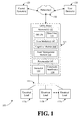
- FIG. 1 is a block diagram of one example system 100 that facilitates the evaluation of load power consumption, according to an illustrative embodiment of the invention.
- the system 100 illustrated in FIG. 1 may include a utility meter or power meter 105 that is connected or attached to a power line 110 configured to supply power to any number of electrical loads 115a-n associated with a structure.
- the system 100 may further include any number of user devices 120 and/or a central system 125 in communication with the power meter 105 via one or more networks 130, such as the Internet and/or an Advanced Metering Infrastructure (“AMI”) network.
- AMI Advanced Metering Infrastructure
- the power meter 105 may be any suitable power meter that may be connected to a distribution system or power distribution grid. A wide variety of suitable power meters may be utilized as desired in various embodiments, such as a single-phase meter or a three-phase meter.
- the power meter 105 may be configured to measure an amount of electrical energy (e.g., kilowatt hours, etc.) or electrical power that is supplied to an associated location, residence, business, household, or machine.
- the power meter 105 may be a smart meter, digital meter, or an advanced meter that is configured to identify consumption in relatively greater detail than a conventional meter.
- a smart power meter 105 may facilitate real-time or near real-time readings, power outage notification, and/or power quality monitoring. Additionally, as described in greater detail below, the power meter 105 may be configured to decompose a monitored power line signal and determine power consumption data for a plurality of individual loads.
- the power meter 105 may include any number of suitable computer processing components that facilitate the operation of the power meter, the decomposition of a monitored power line signal, the comparison of power consumption data for individual loads 115a-n to expected power consumption data, and/or the determination of whether one or more loads 115a-n are operating within desired parameters.
- suitable processing devices that may be incorporated into the power meter 105 include, but are not limited to, application-specific circuits, microcontrollers, minicomputers, other computing devices, and the like.
- the power meter 105 may include any number of processors 141 that facilitate the execution of computer-readable instructions. By executing computer-readable instructions, the power meter 105 may include or form a special purpose computer or particular machine that facilitates the evaluation of load power consumption.
- the power meter 105 may include one or more memory devices 142, one or more sensors 143 and/or one or more communications and/or network interfaces 144.
- the one or more memory devices 142 or memories may include any suitable memory devices, for example, caches, read-only memory devices, random access memory devices, magnetic storage devices, etc.
- the one or more memory devices 142 may store data, executable instructions, and/or various program modules utilized by the power meter 105, for example, data files 145, an operating system ("OS") 146, one or more host modules 147, a cognitive module 148, and/or an asset management module 149.
- OS operating system
- the data files 145 may include any suitable data that facilitates the operation of the power meter 105 including, but not limited to, measurements data taken by the power meter 105 and/or the sensors 143, information associated with identified loads 115a-n, power consumption data for the loads 115a-n, expected power consumption data for the loads 115a-n, desired operating parameters for the loads 115a-n, generated alerts, load profile and/or usage information generated by the power meter 105, power management and/or power distribution data, and/or information that facilitates communication with one or more other components of the system 100.
- the OS 146 may include executable instructions and/or program modules that facilitate and/or control the general operation of the power meter 105. Additionally, the OS 146 may facilitate the execution of other software programs and/or program modules by the processors 141, such as the host modules 147, the cognitive module 148, and/or the asset management module 149.
- the host modules 147 may be suitable software modules that facilitate communication with any number of external devices. Any number of host modules may be provided as desired in various embodiments of the invention.
- a host module 147 may facilitate the establishment of a communications session with a user device 120.
- the host module 147 may provide server functionality that facilitates the establishment of a communications session (e.g., a wide area network session, an Internet session, etc.) between the power meter 105 and the user device 120.
- information such as graphical user interfaces and/or alerts, may be communicated to the user device 120.
- the cognitive module 148 may be a suitable software module that is configured to decompose a monitored power signal into power consumption data for any number of individual loads.
- the cognitive module 148 may utilize model-based embedded intelligence to decompose a power signal measured by the one or more sensors 143 into constituent individual loads.
- the cognitive module 148 may determine an instantaneous state of the power line 110, and the cognitive module 148 may perform a grid scene analysis based at least in part upon the instantaneous state to identify individual and combined load signatures of the various loads 115a-n.
- the one or more sensors 143 may measure voltage and current from the A phase, B phase and neutral wires associated with the power meter 105.
- the A and B phase voltages may be measured from A to neutral, B to neutral and from A to B.
- indoor and outdoor temperatures may also be utilized in one embodiment, in addition to the voltage and current measurements.
- the temperature measurements may be taken directly from the sensors 143 or may be communicated digitally to the meter.
- the temperature data may be received from one or more loads 115a-n, such as an HVAC system, cable TV, commercial freezer, or other load.
- the temperatures may be used by the cognitive decomposition algorithm to more accurately estimate the power consumption of certain loads, such as heat and cooling loads.
- the time of day and/or date may also be used as inputs to the cognitive decomposition algorithm. This information may also come from a wide variety of different sources. The date and time data can be used to help reduce error and simplify the cognitive decomposition algorithms.
- the cognitive module 148 may determine an instantaneous state of the line 110. This includes power load signature detection and preliminary classification. The result is a set of features, data, and metadata that describe the current state of the power line 110.
- the grid state observations may then be analyzed further at a higher level using the previous knowledge accumulated by the power meter 105. This is referred to as grid scene analysis and includes actual identification of individual and combined load signatures of power consuming systems such as household appliances.
- the data of interest may be analyzed over multiple time scales from instantaneous values to identify loads turning on and off to hourly, daily, monthly, and yearly scales to observe longer time scale cycles and trends. A laundry cycle, for example, may take multiple hours to observe a weekly pattern of doing laundry.
- a Bayesian-inference-based classifier can be used for the decomposition algorithm.
- a transient detector may detect and record transient patterns including voltage and current amplitude, before and after differentials, harmonics, phases, and other parameters designated to model a transient.
- a transient index may be obtained from a pre-programmed lookup table of transient patterns. Utilizing stored conditional probability information associated with the likelihood of turning an appliance on and off, a transient pattern may be evaluated, and the cognitive module 148 may identify or select an appliance with the highest probability of creating the observed transient pattern. In this regard, power consumption signatures for particular loads 115a-n may be determined.
- the asset management module 149 may be a suitable software module that is configured to evaluate power consumption data and/or signatures for individual loads 115a-n and determine whether the loads 115a-n are operating within one or more desired parameters and/or desired operating conditions. In operation, the asset management module 149 may receive respective power consumption data, such as power consumption signatures, for a plurality of loads 115a-n from the cognitive module 148. The asset management module 149 may evaluate the power consumption data in order to determine whether the loads 115a-n are operating properly.
- the asset management module 149 may identify expected power consumption data, such as an expected power consumption signature, for a load.
- expected power consumption data such as an expected power consumption signature
- normal or expected power consumption data for an appliance or other electrical load may be received from a manufacturer or other data source and stored in memory.
- historical information associated with the power consumption of the load may be utilized to calculate or determine an expected or baseline power consumption signature for the load.
- any historical period may be evaluated, such as a previous week, a previous month, a previous year, etc.
- seasonal differences and/or ambient conditions may be taken into consideration during the determination of expected power consumption data.
- an expected power consumption for an air conditioning unit may be determined based upon seasonal information and/or information for time periods (e.g., days) having similar conditions to those associated with currently monitored power consumption.
- the asset management module 149 may compare the expected power consumption to a monitored power consumption for the load. Based at least in part upon the comparison, the asset management module 149 may determine whether the load is operating properly. For example, the asset management module 149 may determine whether the power consumption signature for the load satisfies one or more desired operating parameters and/or operating conditions, such as maximum power consumption parameters and/or operating time parameters. As desired, default operating parameters and/or user-defined operating parameters may be utilized. In the event that the load is determined to not be operating properly, the asset management module 149 may take and/or direct any number of control actions. For example, the asset management module 149 may generate an alarm or alert message that is output for communication to a user device 120 and/or central system 125.
- the asset management module 149 may compare a power consumption signature for a load to one or more stored power consumption signatures associated with load faults and/or abnormal conditions. In this regard, the asset management module 149 may identify or diagnose faults and/or abnormal conditions for the load. For example, a power consumption signature for an air conditioner may be compared to a stored signature associated with an air conditioner having a faulty compressor. In the event that a correspondence is identified, then the asset management module 149 may determine that the air conditioner likely has a faulty or failing compressor.
- the asset management module 149 may be configured to generate and/or format any number of messages and/or graphical user interfaces associated with the decomposition of a monitored power signal and/or the evaluation of power consumption data for individual loads. For example, various usage and/or reporting messages may be generated for communication to the central system 125. As another example, various messages and/or graphical user interfaces may be generated for communication to any number of user devices 120. For example, once a communications session (e.g., an Internet communications session, etc.) has been established between the power meter 105 and a user device 120, the asset management module 149 may generate any number of graphical user interfaces (e.g., Web pages, etc.) that may be utilized to present information to the user.
- graphical user interfaces e.g., Web pages, etc.
- the one or more sensors 143 may facilitate the monitoring of the power line 110 and/or the measurements of any number of desired power consumption or energy consumption variables.
- the sensors 143 may monitor voltage and/or current associated with the power line 110.
- the sensors 143 may also monitor a wide variety of other parameters, such as temperature and/or other conditions that may be taken into account by the cognitive module 148.
- a wide variety of different types of sensors may be utilized as desired in various embodiments of the invention, such as voltage sensors, current sensors, temperature sensors, etc.
- the one or more communications or network interfaces 144 may facilitate connection of the power meter 105 to any number of suitable networks, such as one or more network(s) 130 that facilitate communication with user devices 120 and/or the central system 125.
- the power meter 105 may receive data from and/or communicate data to other components of the system 100.
- the power meter 105 may additionally include any number of network cards and/or network interface devices that facilitate communication with the various networks 130.
- the power meter 105 may include a suitable Internet-enabled network card or other communication board that facilitates connection of the power meter 105 to a wide area network.
- the Internet-enabled network card may permit the power meter 105 to establish an Internet Protocol ("IP") address that allows other devices to access the power meter 105 and/or establish a communications session with the power meter 105.
- IP Internet Protocol
- Other examples of network cards and/or communications devices that may be included in the power meter 105 include an AMI board, a Global System for Mobile Communications (“GSM”) transceiver, a General Packet Radio Service (“GPRS”) transceiver, another cellular communications device, a Broadband over Power Lines (“BPL”) adaptor, any number of Ethernet cards, etc.
- GSM Global System for Mobile Communications
- GPRS General Packet Radio Service
- BPL Broadband over Power Lines
- the power meter 105 may typically receive power from a connected power grid and/or power line 110. Additionally, as desired in certain embodiments, the power meter 105 may include any number of suitable back-up power supplies, such as one or more batteries and/or one or more super capacitors.
- the system 100 may include any number of electrical loads 115a-n that are connected to the power line 110 and that receive power from the power line 110 and/or a home power distribution network.
- electrical loads 115a-n may be utilized as desired in various embodiments of the invention, such as various appliances, lights, air conditioners, heaters, etc.
- one or more central systems 125 may be in communication with the power meter 105.
- a central system 125 may be a central system provided by or associated with a power company or other service provider. Additionally, various customers may include systems that function in a similar manner as that described for the central system 125.
- the central system 125 may include any number of processor-driven devices that facilitate the receipt and processing of messages and/or collected data.
- the central system 125 may include any number of personal computing devices, server computers, and/or other computing devices.
- a computing device associated with the central system 125 may include any number of processors, memory devices, and/or communications interfaces. These components may be similar to those described above with reference to the power meter 105.
- the central system 125 may receive and process messages and/or data output by the power meter 105.
- the central system 125 may collect power consumption data, usage data, alerts associated with abnormal conditions (e.g., voltage conditions, current conditions, frequency conditions, etc.).
- the central system 125 may also provide data, such as expected power consumption data, to the power meter 105.
- the processing described as being performed by the cognitive module 148 and/or the asset management module 149 may be performed by the central system 125.
- the central system 125 may host communications sessions in a similar manner as that described above for the power meter 105.
- the central system 125 may include a suitable Web server that outputs graphical user interfaces to user devices 120.
- one or more user devices 120 may be in communication with the power meter 105. Any number of user devices 120 may be utilized as desired in various embodiments, such as mobile devices, personal digital assistants, personal computers, server computers etc. Although user devices 120 are described as devices associated with individual customers or users, other devices may be utilized in various embodiments of the invention to receive information from a power meter 105, such as a server computer and/or analysis system associated with a business or commercial entity.
- a user device 120 may include any number of processor-driven devices that facilitate communication with the power meter 105 and/or the receipt of messages and/or presentation information output by the power meter 105. As such, a user device 120 may include any number of processors, memory devices, and/or communications interfaces.
- a user device 120 may be configured to receive a message output by the power meter 105, such as an email message or a short message service ("SMS") message.
- a user device 120 may request the establishment of a communications session (e.g., an Internet communications session) with the power meter 105. For example, an IP address associated with the power meter 105 may be accessed.
- a communications session e.g., an Internet communications session
- the user device 120 may receive information associated with one or more graphical user interfaces (e.g., Web pages) and/or other messages from the power meter 105, and the user device 120 may format the received information and present at least a portion of the received information to a user.
- graphical user interfaces e.g., Web pages
- a user device 120 may be a device or system associated with a monitored structure, such as a home energy management system or component. Additionally, as desired, the user device 120 may perform a portion of the operations described above as being performed by the cognitive module 148 and/or the asset management module 149. For example, the user device 120 may receive measurements data and/or power signal data from the power meter 105, and the user device 120 may decompose the received information into power consumption information for individual loads. The user device 120 may additionally evaluate each load in order to determine whether the load is operating within one or more predetermined parameters or conditions.
- One or more wide area networks 130 may facilitate communication between the power meter 105, central system 125, and/or user devices 120.
- a wide variety of suitable wide area networks I30 may be utilized as desired in various embodiments of the invention, such as the Internet, a cellular network, a satellite-based network, or any other suitable wide area network.
- embodiments of the invention may include a system 100 with more or less than the components illustrated in FIG. 1 . Additionally, certain components of the system 100 may be combined in various embodiments of the invention.
- the system 100 of FIG. 1 is provided by way of example only.
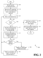
- FIG. 2 is a flow diagram of an example method 200 for evaluating load power consumption, according to an illustrative embodiment of the invention.
- the method 200 may be utilized in association with one or more load power consumption evaluation systems, such as the system 100 illustrated in FIG. 1 .
- the operations of the method 200 may be performed by a suitable cognitive module and/or asset management module incorporated into and/or in communication with a power meter, such as the cognitive module 148 and/or the asset management module 149 associated with the power meter 105 of FIG. 1 .
- the method 200 may begin at block 205.
- a power consumption or an energy consumption signal may be monitored.
- one or more suitable sensors such as the sensors 143 illustrated in FIG. 1 , may monitor one or more energy consumption variables associated with a power line monitored by the power meter 105. Examples of energy consumption variables that may be monitored include a voltage and/or a current on the power line.
- the sensors 143 may generate one or more power consumption output signals that are processed by the cognitive module 148.
- a power consumption signal may be decomposed into power consumption information associated with a plurality of individual loads supplied by the power line, such as the loads 115a-n illustrated in FIG. 1 .
- a power consumption signature for each of the individual loads may be determined by the cognitive module 148.
- a wide variety of suitable methods and/or techniques may be utilized as desired to decompose a monitored power consumption signal, such as those described above with reference to FIG. 1 .
- an instantaneous state of the power line may be determined at various points in time and/or in real-time, and a grid scene analysis may be performed to identify load signatures for the individual loads 115a-n.
- a plurality of individual loads 115a-n may be identified, and power consumption data may be associated with each of the loads 115a-n.
- the individual load data may be processed by the asset management module 149.
- a next electrical load (generically referred to as load 115) may be selected for analysis.
- a determination may be made as to whether the end of the loads 115a-n has been reached. If it is determined at block 220 that the end of the loads 115a-n has been reached, then operations may continue at block 250 described in greater detail below. If, however, it is determined at block 220 that the end of the loads 115a-n has not been reached, then operations may continue at block 225, and the selected load 115 may be evaluated or analyzed.
- expected power consumption information for the selected load 115 may be identified or determined.
- an expected power consumption signature for the selected load 115 may be identified or determined.
- a wide variety of suitable methods and/or techniques may be utilized as desired to identify expected power consumption information for the selected load 115. For example, stored information that has been received from a manufacturer of a load (e.g., an appliance manufacturer, etc.), prestored on the power meter 105, and/or calculated by the power meter 105, may be accessed from memory.
- historical power consumption data for the selected load may be processed to calculate an expected or baseline power consumption signature for the load 115.
- an expected power consumption signature may be adapted over time as the power meter 105 collects and evaluates additional information relating to the load.
- expected power consumption information for the selected load 115 may be compared to the monitored or determined power consumption information for the selected load. For example, a determined power consumption signature may be compared to an expected power consumption signature for the selected load 115.
- a determination may be made based at least in part upon the comparison as to whether any abnormal behavior is detected for the selected load I15. For example, a determination may be made as to whether the selected load is operating within one or more predetermined power consumption parameters or predetermined conditions, such as user-defmed conditions, conditions established from historical data, and/or default conditions. In certain embodiments, a determination may be made as to whether differences between an expected signature and a determined signature exceed one or more threshold values. In other embodiments, a determination may be made as to whether monitored power consumption exceeds one or more threshold values or conditions. In yet other embodiments, a determination may be made as to whether operating time for the selected load exceeds predetermined operating time parameters.
- an operational problem for the selected load 115 may be diagnosed.
- a wide variety of suitable methods and/or techniques may be utilized as desired to diagnose an operational problem. For example, a monitored signature for the selected load 115 may be compared to one or more stored power consumption signatures associated with specific problems for the selected load 115. An operational problem may then be diagnosed based upon an identified or determined correspondence between the monitored signature and a stored signature. For example, a failing compressor operational problem may be identified for an air conditioner based upon a correspondence between a monitored power consumption signature for the air conditioner and a stored signature associated with a failing compressor. Operations may then continue at block 245.
- any number of control actions may be taken or directed based at least in part upon the identified abnormal behavior and/or a diagnosed operational problem.
- suitable control actions include, but are not limited to, turning off the selected load, opening one or more relays that control the provision of power to the selected load, generating an alert message to be communicated to a user and/or central system, and/or documenting an alert.
- alerts and/or diagnosed operational problems may be escalated over time in order to increase the probability of a diagnosed problem being addressed. For example, diagnosed operational problems that persist for a predetermined period of time (e.g., several days, a week, a month, etc.) may result in escalated control actions.
- operations may continue at block 215, and a next load may be selected for evaluation.
- one or more graphical user interfaces and/or reports may be generated.
- the generated graphical user interfaces and/or reports may be provided to one or more recipients (e.g., user devices, a central system, etc.) at block 255.
- the generated interface(s) may include information associated with the operation of the power meter 105, power consumption information for individual loads, expected power consumption information for individual loads, identification of abnormal conditions, information associated with identified or determined operational problems, and/or generated alerts.
- a generated graphical user interface may include a power usage summary or power bill that includes power consumption information for individual loads compared to expected power consumption information.
- the method 200 of FIG. 2 may end following block 255. Alternatively, as desired, the operations of the method 200 may be continuously performed in a repeating loop.
- the operations described and shown in the method 200 of FIG. 2 may be carried out or performed in any suitable order as desired in various embodiments of the invention. Additionally, in certain embodiments, at least a portion of the operations may be carried out in parallel. Furthermore, in certain embodiments, less than or more than the operations described in FIG. 2 may be performed. Additionally, in certain embodiments, the operations set forth in FIG. 2 may be performed in a loop as a location is monitored by a power meter.
- These computer-executable program instructions may be loaded onto a general purpose computer, a special purpose computer, a processor, or other programmable data processing apparatus to produce a particular machine, such that the instructions that execute on the computer, processor, or other programmable data processing apparatus create means for implementing one or more functions specified in the flow diagram block or blocks.
- These computer program instructions may also be stored in a computer-readable memory that can direct a computer or other programmable data processing apparatus to function in a particular manner, such that the instructions stored in the computer-readable memory produce an article of manufacture including instruction means that implement one or more functions specified in the flow diagram block or blocks.
- embodiments of the invention may provide for a computer program product, comprising a computer usable medium having a computer-readable program code or program instructions embodied therein, said computer-readable program code adapted to be executed to implement one or more functions specified in the flow diagram block or blocks.
- the computer program instructions may also be loaded onto a computer or other programmable data processing apparatus to cause a series of operational elements or steps to be performed on the computer or other programmable apparatus to produce a computer-implemented process such that the instructions that execute on the computer or other programmable apparatus provide elements or steps for implementing the functions specified in the flow diagram block or blocks.
- blocks of the block diagrams and flow diagrams support combinations of means for performing the specified functions, combinations of elements or steps for performing the specified functions and program instruction means for performing the specified functions. It will also be understood that each block of the block diagrams and flow diagrams, and combinations of blocks in the block diagrams and flow diagrams, can be implemented by special purpose, hardware-based computer systems that perform the specified functions, elements or steps, or combinations of special purpose hardware and computer instructions.
Landscapes
- Engineering & Computer Science (AREA)
- Power Engineering (AREA)
- Signal Processing (AREA)
- Remote Monitoring And Control Of Power-Distribution Networks (AREA)
Applications Claiming Priority (1)
| Application Number | Priority Date | Filing Date | Title |
|---|---|---|---|
| US13/160,994 US20120323510A1 (en) | 2011-06-15 | 2011-06-15 | Systems, methods, and apparatus for evaluating load power consumption utilizing a power meter |
Publications (1)
| Publication Number | Publication Date |
|---|---|
| EP2535997A2 true EP2535997A2 (de) | 2012-12-19 |
Family
ID=46513637
Family Applications (1)
| Application Number | Title | Priority Date | Filing Date |
|---|---|---|---|
| EP12171479A Withdrawn EP2535997A2 (de) | 2011-06-15 | 2012-06-11 | Systeme, Verfahren und Vorrichtung zur Bewertung von Lastenergieverbrauch unter Verwendung eines Leistungsmessers |
Country Status (3)
| Country | Link |
|---|---|
| US (1) | US20120323510A1 (de) |
| EP (1) | EP2535997A2 (de) |
| CN (1) | CN102854380A (de) |
Cited By (3)
| Publication number | Priority date | Publication date | Assignee | Title |
|---|---|---|---|---|
| WO2017064494A1 (en) * | 2015-10-14 | 2017-04-20 | British Gas Trading Limited | Method and system for assessing usage of devices of a property |
| EP3188339A4 (de) * | 2014-08-26 | 2017-10-11 | Gree Electric Appliances, Inc. of Zhuhai | Verfahren, vorrichtung und system zur steuerung einer verteilten stromquelle |
| CN119865431A (zh) * | 2024-12-23 | 2025-04-22 | 南方电网数字电网科技(广东)有限公司 | 电力终端互联通信模型的构建方法、设备、介质及程序产品 |
Families Citing this family (33)
| Publication number | Priority date | Publication date | Assignee | Title |
|---|---|---|---|---|
| GB2478117B (en) | 2010-02-24 | 2012-09-12 | Alertme Com Ltd | Apparatus and method for detecting degradation in heating system performance |
| US8884553B2 (en) | 2011-10-19 | 2014-11-11 | Justin Hai | Current monitor for indicating condition of attached electrical apparatus |
| US9140727B2 (en) * | 2011-10-19 | 2015-09-22 | Green Fitness Equipment Company, Llc | Current monitor for indicating condition of attached electrical apparatus |
| US8914629B2 (en) * | 2012-01-30 | 2014-12-16 | The Nielsen Company (Us), Llc | Intercepting encrypted network traffic for internet usage monitoring |
| US9638545B2 (en) * | 2012-05-16 | 2017-05-02 | Kyocera Corporation | Power management apparatus, power management system and power management method |
| US20140228993A1 (en) * | 2013-02-14 | 2014-08-14 | Sony Europe Limited | Apparatus, system and method for control of resource consumption and / or production |
| US10962248B1 (en) * | 2013-07-15 | 2021-03-30 | EnTouch Controls Inc. | Method of auto association of HVAC energy with control signal for self diagnostics of the HVAC system |
| CN104300672A (zh) * | 2013-07-16 | 2015-01-21 | 中兴通讯股份有限公司 | 智能限电方法、装置及系统 |
| US10318895B1 (en) | 2013-08-27 | 2019-06-11 | Curb, Inc. | System for promoting efficient use of resources |
| DK2946568T3 (en) | 2014-04-09 | 2017-02-20 | Smappee Nv | ENERGY MANAGEMENT SYSTEM |
| EP2946568B1 (de) | 2014-04-09 | 2016-12-14 | Smappee NV | Energieverwaltungssystem |
| US11190400B2 (en) | 2014-08-06 | 2021-11-30 | Belkin International, Inc. | Identifying and automating a device type using image data |
| US9967145B2 (en) * | 2014-11-21 | 2018-05-08 | Belkin International Inc. | System for utility usage triggering action |
| CN107209913B (zh) * | 2014-11-17 | 2021-09-17 | 库尔布股份有限公司 | 利用装置特定的通知来管理资源消耗 |
| US20160349293A1 (en) * | 2015-05-28 | 2016-12-01 | Intel Corporation | Apparatus and method for condition monitoring of multiple electrical sub-systems |
| EP3625646A4 (de) * | 2017-05-15 | 2021-03-17 | Hubbell Incorporated | System und verfahren zur steuerung eines elektrischen behälters auf der grundlage eines betriebsprofils |
| US11307117B2 (en) * | 2017-09-04 | 2022-04-19 | Amper Technologies, Inc. | System and method for interpretation and analysis of manufacturing activity |
| US10677825B2 (en) * | 2017-10-02 | 2020-06-09 | Eaton Intelligent Power Limited | System and method for detecting theft of electricity using meter data disaggregation |
| US11581725B2 (en) | 2018-07-07 | 2023-02-14 | Intelesol, Llc | Solid-state power interrupters |
| US11349296B2 (en) | 2018-10-01 | 2022-05-31 | Intelesol, Llc | Solid-state circuit interrupters |
| US11336199B2 (en) * | 2019-04-09 | 2022-05-17 | Intelesol, Llc | Load identifying AC power supply with control and methods |
| US12152921B2 (en) | 2019-05-06 | 2024-11-26 | Badger Meter, Inc. | System and method for utilizing district metering areas based on meter designations |
| US10677629B1 (en) * | 2019-05-06 | 2020-06-09 | Badger Meter, Inc. | System and method for utilizing district metering areas based on meter designations |
| US11170964B2 (en) | 2019-05-18 | 2021-11-09 | Amber Solutions, Inc. | Intelligent circuit breakers with detection circuitry configured to detect fault conditions |
| CN111286759B (zh) * | 2020-03-27 | 2021-03-02 | 国网山东省电力公司电力科学研究院 | 一种电解铝负荷参与电网紧急控制的控制方法及系统 |
| EP4314726A4 (de) * | 2021-04-02 | 2025-01-22 | Badger Meter. Inc. | System und verfahren zur verwendung von fernmessbereichen auf basis von zählerbezeichnungen |
| CN113127300A (zh) * | 2021-04-09 | 2021-07-16 | 山东英信计算机技术有限公司 | 一种系统功率的监测和调节方法、装置、设备及可读介质 |
| EP4152892B1 (de) * | 2021-09-21 | 2025-04-30 | Helvar Oy Ab | Beleuchtungssystemverwaltung |
| US12113525B2 (en) | 2021-09-30 | 2024-10-08 | Amber Semiconductor, Inc. | Intelligent electrical switches |
| US11762010B2 (en) * | 2021-10-15 | 2023-09-19 | Sacramento Municipal Utility District | Systems and methods for energy diagnostics to identify equipment malfunctions |
| US12348028B2 (en) | 2021-10-22 | 2025-07-01 | Amber Semiconductor, Inc. | Multi-output programmable power manager |
| US12362646B2 (en) | 2022-01-26 | 2025-07-15 | Amber Semiconductor, Inc. | Controlling AC power to inductive loads |
| WO2024194981A1 (ja) * | 2023-03-20 | 2024-09-26 | 日本電気株式会社 | 電力量計算装置、方法、及びコンピュータ可読媒体 |
Citations (1)
| Publication number | Priority date | Publication date | Assignee | Title |
|---|---|---|---|---|
| US7693670B2 (en) | 2007-08-14 | 2010-04-06 | General Electric Company | Cognitive electric power meter |
Family Cites Families (4)
| Publication number | Priority date | Publication date | Assignee | Title |
|---|---|---|---|---|
| CN1028065C (zh) * | 1993-12-31 | 1995-03-29 | 上海集能电器设备有限公司 | 三相异步电机节能控制的最小输入功率方法及其装置 |
| JPH0950590A (ja) * | 1995-08-08 | 1997-02-18 | Toshiba Meter Techno Kk | 負荷コントロール機能付きロードサーベイシステム |
| TWI364518B (en) * | 2008-07-29 | 2012-05-21 | Ind Tech Res Inst | Power saving managing method and system using the same |
| US8653968B2 (en) * | 2009-12-23 | 2014-02-18 | Pulse Energy Inc. | Systems and methods for predictive building energy monitoring |
-
2011
- 2011-06-15 US US13/160,994 patent/US20120323510A1/en not_active Abandoned
-
2012
- 2012-06-11 EP EP12171479A patent/EP2535997A2/de not_active Withdrawn
- 2012-06-15 CN CN2012102964322A patent/CN102854380A/zh active Pending
Patent Citations (1)
| Publication number | Priority date | Publication date | Assignee | Title |
|---|---|---|---|---|
| US7693670B2 (en) | 2007-08-14 | 2010-04-06 | General Electric Company | Cognitive electric power meter |
Cited By (8)
| Publication number | Priority date | Publication date | Assignee | Title |
|---|---|---|---|---|
| EP3188339A4 (de) * | 2014-08-26 | 2017-10-11 | Gree Electric Appliances, Inc. of Zhuhai | Verfahren, vorrichtung und system zur steuerung einer verteilten stromquelle |
| US10147148B2 (en) | 2014-08-26 | 2018-12-04 | Gree Electric Appliances Inc. Of Zhuhai | Distributed energy power source control method, apparatus and system for providing loads with dynamic power distribution modes |
| WO2017064494A1 (en) * | 2015-10-14 | 2017-04-20 | British Gas Trading Limited | Method and system for assessing usage of devices of a property |
| WO2017064492A1 (en) * | 2015-10-14 | 2017-04-20 | British Gas Trading Limited | Method and system for determining energy consumption of a property |
| US11183842B2 (en) | 2015-10-14 | 2021-11-23 | British Gas Trading Limited | Method and system for determining energy consumption of a property |
| US11309710B2 (en) | 2015-10-14 | 2022-04-19 | British Gas Trading Limited | Method and system for assessing usage of devices of a property |
| CN119865431A (zh) * | 2024-12-23 | 2025-04-22 | 南方电网数字电网科技(广东)有限公司 | 电力终端互联通信模型的构建方法、设备、介质及程序产品 |
| CN119865431B (zh) * | 2024-12-23 | 2025-10-17 | 南方电网数字电网科技(广东)有限公司 | 电力终端互联通信模型的构建方法、设备、介质及程序产品 |
Also Published As
| Publication number | Publication date |
|---|---|
| US20120323510A1 (en) | 2012-12-20 |
| CN102854380A (zh) | 2013-01-02 |
Similar Documents
| Publication | Publication Date | Title |
|---|---|---|
| EP2535997A2 (de) | Systeme, Verfahren und Vorrichtung zur Bewertung von Lastenergieverbrauch unter Verwendung eines Leistungsmessers | |
| Karthick et al. | Design of IoT based smart compact energy meter for monitoring and controlling the usage of energy and power quality issues with demand side management for a commercial building | |
| US8635036B2 (en) | Systems, methods, and apparatus for providing energy management utilizing a power meter | |
| US9823283B2 (en) | Multi-node electrical power monitoring, analysis, and related services | |
| US9797935B2 (en) | Device, arrangement and method for verifying the operation of electricity meter | |
| US20150268281A1 (en) | System and method for monitoring, analyzing and acting upon electricity patterns | |
| US20130066479A1 (en) | Energy consumption disaggregation system | |
| JP2015029418A (ja) | 電力監視装置、識別方法及び生成方法 | |
| US9857414B1 (en) | Monitoring and fault detection of electrical appliances for ambient intelligence | |
| CN111353911A (zh) | 电力设备运维方法、系统、设备和存储介质 | |
| WO2021176459A1 (en) | A system and method of energy disaggregation using nonintrusive load monitoring | |
| AU2012200037A1 (en) | Systems, methods, and apparatus for providing security services utilizing a smart utility meter | |
| US11125790B2 (en) | Method for operating a power consumption metering system and power consumption metering system | |
| Silagpo et al. | Monitoring and Prediction of Household Power Consumption using Internet of Things and ARIMA | |
| Lu et al. | The development of a smart distribution grid testbed for integrated information management systems | |
| Sulayman et al. | Smart grid monitoring using local area sensor network. Real-time data acquisition, analysis and management | |
| US20250290957A1 (en) | Motor diagnostics systems and methods | |
| Mikkola et al. | Near real time energy monitoring for end users: Requirements and sample applications | |
| EP3276773A1 (de) | Erkennung der betrügerischen produktion von ököstrom in intelligenten stromnetzen | |
| Nugroho et al. | Design and implementation of an iot-based electrical energy monitoring system in commercial buildings | |
| CN117289043A (zh) | 检测由电能质量事件引起的掉落负载的方法和系统 | |
| Guo et al. | Evaluating feedback systems for residential building energy monitoring |
Legal Events
| Date | Code | Title | Description |
|---|---|---|---|
| PUAI | Public reference made under article 153(3) epc to a published international application that has entered the european phase |
Free format text: ORIGINAL CODE: 0009012 |
|
| AK | Designated contracting states |
Kind code of ref document: A2 Designated state(s): AL AT BE BG CH CY CZ DE DK EE ES FI FR GB GR HR HU IE IS IT LI LT LU LV MC MK MT NL NO PL PT RO RS SE SI SK SM TR |
|
| AX | Request for extension of the european patent |
Extension state: BA ME |
|
| STAA | Information on the status of an ep patent application or granted ep patent |
Free format text: STATUS: THE APPLICATION IS DEEMED TO BE WITHDRAWN |
|
| 18D | Application deemed to be withdrawn |
Effective date: 20150106 |