EP2535967A1 - Electric storage element and production method thereof - Google Patents
Electric storage element and production method thereof Download PDFInfo
- Publication number
- EP2535967A1 EP2535967A1 EP12172143A EP12172143A EP2535967A1 EP 2535967 A1 EP2535967 A1 EP 2535967A1 EP 12172143 A EP12172143 A EP 12172143A EP 12172143 A EP12172143 A EP 12172143A EP 2535967 A1 EP2535967 A1 EP 2535967A1
- Authority
- EP
- European Patent Office
- Prior art keywords
- shaft
- casing
- external terminal
- current collector
- cover
- Prior art date
- Legal status (The legal status is an assumption and is not a legal conclusion. Google has not performed a legal analysis and makes no representation as to the accuracy of the status listed.)
- Granted
Links
- 238000003860 storage Methods 0.000 title abstract description 12
- 238000004519 manufacturing process Methods 0.000 title abstract description 6
- 238000003466 welding Methods 0.000 description 10
- 230000002093 peripheral effect Effects 0.000 description 8
- 229910052782 aluminium Inorganic materials 0.000 description 4
- XAGFODPZIPBFFR-UHFFFAOYSA-N aluminium Chemical compound [Al] XAGFODPZIPBFFR-UHFFFAOYSA-N 0.000 description 4
- 239000012212 insulator Substances 0.000 description 4
- RYGMFSIKBFXOCR-UHFFFAOYSA-N Copper Chemical compound [Cu] RYGMFSIKBFXOCR-UHFFFAOYSA-N 0.000 description 3
- 239000007788 liquid Substances 0.000 description 3
- 229910052751 metal Inorganic materials 0.000 description 3
- 239000002184 metal Substances 0.000 description 3
- 238000000034 method Methods 0.000 description 3
- 239000011255 nonaqueous electrolyte Substances 0.000 description 3
- 229910052802 copper Inorganic materials 0.000 description 2
- 239000010949 copper Substances 0.000 description 2
- 238000002347 injection Methods 0.000 description 2
- 239000007924 injection Substances 0.000 description 2
- 238000005192 partition Methods 0.000 description 2
- 238000007789 sealing Methods 0.000 description 2
- 229920003002 synthetic resin Polymers 0.000 description 2
- 239000000057 synthetic resin Substances 0.000 description 2
- 229910000838 Al alloy Inorganic materials 0.000 description 1
- HBBGRARXTFLTSG-UHFFFAOYSA-N Lithium ion Chemical compound [Li+] HBBGRARXTFLTSG-UHFFFAOYSA-N 0.000 description 1
- 230000002159 abnormal effect Effects 0.000 description 1
- 239000003990 capacitor Substances 0.000 description 1
- 239000004020 conductor Substances 0.000 description 1
- 239000011889 copper foil Substances 0.000 description 1
- 230000003247 decreasing effect Effects 0.000 description 1
- 230000002349 favourable effect Effects 0.000 description 1
- 239000011888 foil Substances 0.000 description 1
- 229910001416 lithium ion Inorganic materials 0.000 description 1
- 238000003825 pressing Methods 0.000 description 1
- 229920005989 resin Polymers 0.000 description 1
- 239000011347 resin Substances 0.000 description 1
Images





Classifications
-
- H—ELECTRICITY
- H01—ELECTRIC ELEMENTS
- H01M—PROCESSES OR MEANS, e.g. BATTERIES, FOR THE DIRECT CONVERSION OF CHEMICAL ENERGY INTO ELECTRICAL ENERGY
- H01M50/00—Constructional details or processes of manufacture of the non-active parts of electrochemical cells other than fuel cells, e.g. hybrid cells
- H01M50/50—Current conducting connections for cells or batteries
- H01M50/543—Terminals
-
- H—ELECTRICITY
- H01—ELECTRIC ELEMENTS
- H01M—PROCESSES OR MEANS, e.g. BATTERIES, FOR THE DIRECT CONVERSION OF CHEMICAL ENERGY INTO ELECTRICAL ENERGY
- H01M50/00—Constructional details or processes of manufacture of the non-active parts of electrochemical cells other than fuel cells, e.g. hybrid cells
- H01M50/10—Primary casings; Jackets or wrappings
- H01M50/172—Arrangements of electric connectors penetrating the casing
- H01M50/174—Arrangements of electric connectors penetrating the casing adapted for the shape of the cells
- H01M50/176—Arrangements of electric connectors penetrating the casing adapted for the shape of the cells for prismatic or rectangular cells
-
- H—ELECTRICITY
- H01—ELECTRIC ELEMENTS
- H01M—PROCESSES OR MEANS, e.g. BATTERIES, FOR THE DIRECT CONVERSION OF CHEMICAL ENERGY INTO ELECTRICAL ENERGY
- H01M50/00—Constructional details or processes of manufacture of the non-active parts of electrochemical cells other than fuel cells, e.g. hybrid cells
- H01M50/10—Primary casings; Jackets or wrappings
- H01M50/147—Lids or covers
-
- H—ELECTRICITY
- H01—ELECTRIC ELEMENTS
- H01M—PROCESSES OR MEANS, e.g. BATTERIES, FOR THE DIRECT CONVERSION OF CHEMICAL ENERGY INTO ELECTRICAL ENERGY
- H01M50/00—Constructional details or processes of manufacture of the non-active parts of electrochemical cells other than fuel cells, e.g. hybrid cells
- H01M50/50—Current conducting connections for cells or batteries
- H01M50/543—Terminals
- H01M50/547—Terminals characterised by the disposition of the terminals on the cells
- H01M50/55—Terminals characterised by the disposition of the terminals on the cells on the same side of the cell
-
- H—ELECTRICITY
- H01—ELECTRIC ELEMENTS
- H01M—PROCESSES OR MEANS, e.g. BATTERIES, FOR THE DIRECT CONVERSION OF CHEMICAL ENERGY INTO ELECTRICAL ENERGY
- H01M50/00—Constructional details or processes of manufacture of the non-active parts of electrochemical cells other than fuel cells, e.g. hybrid cells
- H01M50/50—Current conducting connections for cells or batteries
- H01M50/543—Terminals
- H01M50/552—Terminals characterised by their shape
- H01M50/553—Terminals adapted for prismatic, pouch or rectangular cells
-
- H—ELECTRICITY
- H01—ELECTRIC ELEMENTS
- H01M—PROCESSES OR MEANS, e.g. BATTERIES, FOR THE DIRECT CONVERSION OF CHEMICAL ENERGY INTO ELECTRICAL ENERGY
- H01M50/00—Constructional details or processes of manufacture of the non-active parts of electrochemical cells other than fuel cells, e.g. hybrid cells
- H01M50/50—Current conducting connections for cells or batteries
- H01M50/543—Terminals
- H01M50/562—Terminals characterised by the material
-
- H—ELECTRICITY
- H01—ELECTRIC ELEMENTS
- H01M—PROCESSES OR MEANS, e.g. BATTERIES, FOR THE DIRECT CONVERSION OF CHEMICAL ENERGY INTO ELECTRICAL ENERGY
- H01M50/00—Constructional details or processes of manufacture of the non-active parts of electrochemical cells other than fuel cells, e.g. hybrid cells
- H01M50/50—Current conducting connections for cells or batteries
- H01M50/543—Terminals
- H01M50/564—Terminals characterised by their manufacturing process
- H01M50/566—Terminals characterised by their manufacturing process by welding, soldering or brazing
-
- Y—GENERAL TAGGING OF NEW TECHNOLOGICAL DEVELOPMENTS; GENERAL TAGGING OF CROSS-SECTIONAL TECHNOLOGIES SPANNING OVER SEVERAL SECTIONS OF THE IPC; TECHNICAL SUBJECTS COVERED BY FORMER USPC CROSS-REFERENCE ART COLLECTIONS [XRACs] AND DIGESTS
- Y02—TECHNOLOGIES OR APPLICATIONS FOR MITIGATION OR ADAPTATION AGAINST CLIMATE CHANGE
- Y02E—REDUCTION OF GREENHOUSE GAS [GHG] EMISSIONS, RELATED TO ENERGY GENERATION, TRANSMISSION OR DISTRIBUTION
- Y02E60/00—Enabling technologies; Technologies with a potential or indirect contribution to GHG emissions mitigation
- Y02E60/10—Energy storage using batteries
-
- Y—GENERAL TAGGING OF NEW TECHNOLOGICAL DEVELOPMENTS; GENERAL TAGGING OF CROSS-SECTIONAL TECHNOLOGIES SPANNING OVER SEVERAL SECTIONS OF THE IPC; TECHNICAL SUBJECTS COVERED BY FORMER USPC CROSS-REFERENCE ART COLLECTIONS [XRACs] AND DIGESTS
- Y10—TECHNICAL SUBJECTS COVERED BY FORMER USPC
- Y10T—TECHNICAL SUBJECTS COVERED BY FORMER US CLASSIFICATION
- Y10T29/00—Metal working
- Y10T29/49—Method of mechanical manufacture
- Y10T29/49002—Electrical device making
- Y10T29/49117—Conductor or circuit manufacturing
Definitions
- the present invention relates to an electric storage element and a production method thereof.
- JP 2009-087727 A and JP 2009-087728 A each disclose a conventional battery configured such that each of a body and a distal end of a shaft of an external terminal is sequentially inserted into a through hole provided in a cover and a shaft through hole provided in an insulator with a gasket being interposed therebetween, and is then inserted into a shaft through hole provided in a first plate, and thereafter the distal end of the shaft is caulked, so that the cover, the insulator, and the first plate are held and integrated by the external terminal.
- JP 2009-087693 A discloses a configuration in which a rivet portion of a rivet is caulked so as to press a projecting contact body of a current collector, and then the rivet portion and the current collector are welded by laser beams to form a welded portion.
- JP 2009-087727 A and JP 2009-087728 A the cover, the insulator, and the first plate are simply held and integrated by the external terminal.
- the gasket and the insulator are essentially provided in order to keep air tightness in the battery.
- JP 2009-087693 A merely refers to a feature in the configuration, that the rivet portion and the current collector are welded by laser beams, and the object thereof is to simply achieve a rigid fixed state.
- JP 2009-087693 A neither describes nor suggests air tightness.
- Such an electric storage element has excellent air tightness and strong connection at a portion connected with an external terminal, and realizes high assembling performance, even in a simple configuration.
- an electric storage element includes a casing, an external terminal having a surface exposed outward from the casing, a current collector provided inside the casing and connected to the external terminal, and an electrode assembly provided inside the casing and connected to the current collector, wherein the casing has a through hole, and the external terminal includes a flange in contact with an outer surface of the casing, and a first shaft extending from the flange to be inserted into the through hole in the casing and welded thereto.
- This configuration has a welded portion where the first shaft as part of the external terminal is fitted into the through hole in the casing. Therefore, it is possible to secure sufficient air tightness with no need for any extra sealing member.
- the external terminal further includes a second shaft that has a diameter smaller than that of the first shaft, and extends from the first shaft to be fixed to the current collector.
- the casing and the current collector are integrated with each other with no need for any extra component or work, and electrical connection is achieved between the current collector and the casing.
- the second shaft is smaller in diameter than the first shaft. Accordingly, the first shaft is easily inserted into the through hole in the casing to be welded thereto, while the work is not disturbed by the second shaft.
- the first shaft is inserted into the through hole in the casing, and with the flange being in contact with the outer surface of the casing, a stepped portion from the second shaft has a height substantially flush with an inner surface of the casing.
- This configuration further facilitates the work of welding the first shaft.
- the casing may comprise a battery case having an open surface, and a cover closing the opening of the battery case.
- the through hole of the casing may be provided in the cover.
- the cover has an engagement receiver swelled outward, and the current collector has a fitting portion that is located in corresponding one of the engagement receivers and has a through hole into which the first shaft is inserted to be welded thereto.
- the external terminal is a positive external terminal, and electrically connects the cover and the current collector when the current collector is fixed to the cover.
- the positive external terminal equalizes potential of the cover and that of the current collector, with no need for extra work such as welding in order to electrically connect the cover with the current collector.
- the first shaft is inserted into the through hole in the casing, and a contact portion therebetween is welded over the entire periphery.
- the contact portion therebetween is welded over the entire periphery, so that the strength at the contact portion is increased to keep an excellent support state.
- the electric storage element may be produced in the following manner.
- a method of producing an electric storage element including a casing, an external terminal having a surface exposed outward from the casing, a current collector provided inside the casing and connected to the external terminal, and an electrode assembly provided inside the casing and connected to the current collector, wherein the casing is configured by a battery case having an open surface and a cover closing the opening of the battery case, and the external terminal includes a flange, a first shaft extending from the flange, and a second shaft having a diameter smaller than that of the first shaft and extending from the first shaft.
- the method includes inserting the first shaft of the external terminal into a through hole provided in the cover, welding the first shaft of the external terminal to the through hole in the cover, inserting the second shaft of the external terminal into a through hole provided in the current collector, and caulking the second shaft of the external terminal so as to hold the cover and the current collector between the flange of the external terminal and the caulked second shaft.
- the external terminal is provided with the first shaft, which is fitted into the through hole in the casing and is welded thereto, so as to integrate the current collector with the casing. Therefore, it is possible to secure air tightness at the portion connected with the external terminal as well as achieve electrical connection between the current collector and the casing, with no need for any extra component.
- Fig. 1 is a perspective view of a battery according to an embodiment of the present invention
- Fig. 2 is a front sectional view of the battery according to the embodiment of the present invention.
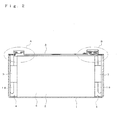
- Fig. 3 is a perspective view, seen from above, of a cover shown in Fig. 1 ;
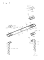
- Fig. 4 is an exploded perspective view, seen from above, of the battery shown in Fig. 3 ;
- Fig. 5 is an enlarged view of a portion A shown in Fig. 2 ;
- Fig. 6 is an enlarged view of a portion B shown in Fig. 2 ;
- Fig. 7 is an exploded perspective view, seen from below, of the cover shown in Fig. 1 ;
- Fig. 8 is an exploded sectional view of Fig. 5 ;
- Fig. 9 is a sectional view showing a state where a positive external terminal is assembled to the cover from the state shown in Fig. 8 ;
- Fig. 10 is a sectional view showing a state where a current collector is further assembled from the state shown in Fig. 9 .
- Fig. 1 shows a nonaqueous electrolyte secondary battery that exemplifies an electrochemical cell.
- a battery case 1 houses an electrode assembly 2 and is sealed with a cover 3.
- the battery case 1 and the cover 3 configure a casing.
- the battery case 1 has a rectangular parallelepiped shape with an open upper surface, and is made of aluminum, an aluminum alloy, or the like.
- the electrode assembly 2 includes a positive electrode 4 made of aluminum foil, a negative electrode 5 made of copper foil, and a separator 6 made of a porous resin film and interposed between the positive electrode 4 and the negative electrode 5, similarly to a conventional electrode assembly.
- Each of these members has a belt shape, and the positive electrode 4 and the negative electrode 5 are each wound into a flat shape so as to be housed in the battery case 1 in a state where the positive electrode 4 and the negative electrode 5 are displaced from each other at the opposite ends in the width direction of the separator 6.
- a positive current collector 18 is connected to the positive electrode 4 with a clip 7 being interposed therebetween, and a negative current collector 19 is connected to the negative electrode 5 with a clip 7 being interposed therebetween.
- the cover 3 is made of a metal plate in a long rectangular shape in a planar view, and is provided, in the center thereof, with an opening 8 that has a substantially elliptical shape and is formed to be stepped from the upper surface.
- a metal safety valve 9 is attached into the opening 8.
- the safety valve 9 is provided with a thin portion in a substantially H letter shape. The thin portion is torn in a case of abnormal increase in internal pressure, so that the pressure can be decreased.
- the cover 3 has an end provided with a liquid injection hole 10 having a small diameter, and the liquid injection hole 10 is configured to be closed by a plug 11 after liquid is injected.
- the cover 3 is provided, at the two ends, with a first engagement receiver 12A and a second engagement receiver 12B, respectively.
- the first and second engagement receivers 12A and 12B each have a rectangular shape in a planar view and are swelled upward.
- the cover 3 has a lower surface provided with a guide recess 12b.
- a through hole 12c is provided in the center of a ceiling surface configuring each engagement recess 12a.
- a current collector 13 and an external terminal 14 are attached directly to the first engagement receiver 12A.
- another current collector 13 and another external terminal 14 are attached to the second engagement receiver 12B with an upper gasket 15 and a lower gasket 16 being interposed therebetween, respectively.
- the cover 3 is provided, in the vicinity of inside the engagement receiver 12B in the longitudinal direction of the cover 3, with lock projections 17 that project upward from two positions in the width direction of the cover 3.
- Each of the lock projections 17 has a cylindrical shape provided with a bottom, and is formed at the same time when the cover 3 is pressed.
- the upper gasket 15, which is to be described later, is locked to the respective lock projections 17, so as to achieve positioning in a rotational direction.
- the current collectors 13 are provided as the positive current collector 18 made of aluminum and the negative current collector 19 made of copper. Each of the current collectors 13 is formed by pressing a long metal plate, so as to be provided with a connection receiver 20 and legs 21 that extend from respective ends of the connection receiver 20.
- the connection receiver 20 is configured by a fitting portion 22 that is located in the engagement recess 12a of the cover 3 and a seat 23 that is formed continuously from the fitting portion 22.
- the fitting portion 22 is made flat and is provided with a through hole 22a in the center thereof.
- the fitting portion 22 has a peripheral edge provided with a guide edge 24 that is located on three sides and extends perpendicularly from the fitting portion 22.
- the remaining side of the peripheral edge of the fitting portion 22 configures a continuous portion 25 that extends longer than the guide edge 24 so as to be provided continuously to the seat 23.
- the guide edge 24 and the continuous portion 25 sufficiently enhance rigidity of the connection receiver 20 of each of the current collectors 13.
- the legs 21 extend perpendicularly from the two opposite edges of the seat 23 so as to be located along both side surfaces of the electrode assembly 2.
- the legs 21 are connected to the positive electrode 4 or the negative electrode 5 of the electrode assembly 2 with the clip 7 (see Fig. 2 ) being interposed therebetween. Positional deviation can be prevented by the clip 7 that is held between the opposite inner surfaces of the battery case 1.
- the external terminals 14 are provided as a positive external terminal 28 and a negative external terminal 29.
- Each of the external terminals 14 is configured by a flat plate 30 and a shaft 31 extending downward from the center of the lower surface of the flat plate 30.
- a bus bar (not shown) is connected by welding to the upper surface (exposed surface) of the flat plate 30.
- the positive external terminal 28 is made of a conductive material such as aluminum and has a rivet shape and includes a flange 32, a first shaft 33, and a second shaft 34.
- the flange 32 has a rectangular shape in a planar view.
- the first shaft 33 projects from the center of the flange 32, and the second shaft 34 has a diameter smaller than that of the first shaft 33 and projects from the center of the first shaft 33.
- the first shaft 33 is sized to have an outer diameter so as to be located in the through hole 12c in the first engagement receiver 12A provided on the cover 3 with no or substantially no gap being formed therein.
- the first shaft 33 is formed to have a height such that a stepped portion 35 between the first shaft 33 and the second shaft 34 is substantially flush with the inner surface of the cover 3 in a state where the first shaft 33 is inserted into the through hole 12c and the flange 32 is in contact with the outer surface of the cover 3.
- the first shaft 33 is inserted into the through hole 12c in the cover 3, and the contact portion therebetween is welded over the entire periphery in this state (by laser welding, micro TIG welding, or the like). Accordingly, the positive external terminal 28 can be attached to the cover 3 so as to sufficiently enhance air tightness, with no need for any extra member.
- the second shaft 34 is sized to have an outer diameter so as to be inserted into the through hole 22a in the current collector 13, preferably with no or substantially no gap being formed therebetween.
- the second shaft 34 is inserted into the through hole 22a in the current collector 13 and is caulked in a state where the inner surface (lower surface) of the engagement recess 12a configuring the first engagement receiver 12A on the cover 3 is in surface contact with the upper surface of the current collector 13.
- the current collector 13 is fixed by the positive external terminal 28 welded to the cover 3, such that the current collector 13 is in intimate contact with the engagement recess 12a in the cover 3.
- the welded portion between the outer peripheral edge of the first shaft 33 and the inner peripheral edge of the through hole 12c in the cover 3 is completely covered with the fitting portion 22 of the positive current collector 18. Therefore, the welded portion can be kept in a favorable state.
- the entire negative external terminal 29 is made of copper, and the flat plate 30 and the shaft 31 are formed integrally with each other.
- the upper gasket 15 is made of a synthetic resin, such that the inner space of a frame having a rectangular shape in a planar view is divided by a partition 36 into an upper terminal holding recess 37 and a lower attachment recess 38. Tongue pieces 39 extend laterally from one of sides configuring an edge of a lower opening.
- a cylindrical portion 36a Provided in the center of the partition 36 is a cylindrical portion 36a that extends downward from the ceiling surface.
- the cylindrical portion 36a is inserted into the through hole 12c in the second engagement receiver 12B and is fitted into a through hole 40a provided in the lower gasket 16.
- Lock holes 39a are provided in the two tongue pieces 39, into which the lock projections 17 on the cover 3 are inserted, respectively.
- the upper gasket 15 is provided along the second engagement receiver 12B that is located on the cover 3 and has a rectangular shape in a planar view, so that positional deviation of the upper gasket 15 can be prevented in the rotational direction by simply mounting the upper gasket 15 on the engagement receiver 12B.
- the lock projections 17 are inserted respectively into the lock holes 39a, so as to securely prevent such positional deviation in the rotational direction.
- the lower gasket 16 is made of a synthetic resin, has a rectangular plate shape in a planar view, and is provided, in the center thereof, with a through hole 16a.
- the lower gasket 16 is located in the engagement recess 12a configuring the engagement receiver 12B, so as to seal the through hole 12c provided therein.
- the second shaft 34 of the positive external terminal 28 is inserted into the through hole 12c from the outer surface (upper surface) of the engagement recess 12a, and as shown in Fig. 9 , the flange 32 is brought into contact with the outer surface of the engagement recess 12a.
- the first shaft 33 is located in the through hole 12c, and the stepped portion 35 at the boundary between the first shaft 33 and the second shaft 34 is made substantially flush with the lower surface of the cover 3.
- the adjacent (contact) portion between the outer peripheral surface of the first shaft 33 and the inner peripheral surface of the through hole 12c is sealed by laser welding or the like.
- the positive external terminal 28 is integrated to the cover 3, and also improved is air tightness in the through hole 12c, into which the first shaft 33 is inserted.
- the sealed portion is not the peripheral edge where the second shaft 34 projects, but the peripheral edge of the through hole 12c in the cover 3, in other words, a flat surface. This configuration facilitates the sealing work even by welding (in the case of laser welding, laser beams can be applied easily). Moreover, the sealed portion can be made flat with no projection being formed (even with any projection, the sealed portion can be refined easily).
- the fitting portion 22 of the connection receiver 20 configuring the current collector 13 is located in the engagement recess 12a in the first engagement receiver 12A, and the second shaft 34 of the positive external terminal 28 is inserted into the through hole 22a.
- the second shaft 34 is then caulked, so that, as shown in Fig. 5 , the cover 3 and the fitting portion 22 of the current collector 13 are pressed against each other and are kept electrically connected to each other.
- the attachment recess 38 in the upper gasket 15 is attached to cover the swelled portion due to provision of the engagement recess 12a.
- the cylindrical portion 36a of the upper gasket 15 is attached into the through hole 12c in the cover 3, and the lock projections 17 on the cover 3 are locked into the lock holes 39a provided in the tongue pieces 39 of the upper gasket 15, respectively.
- the lower gasket 16 and the fitting portion 22 of the current collector 13 are sequentially located in the engagement recess 12a in the cover 3, and the shaft 31 of the negative external terminal 29 is inserted into the cylindrical portion 36a of the upper gasket 15, the through hole 16a in the lower gasket 16, and the through hole 22a in the fitting portion 22 of the current collector 13. Thereafter, the shaft 31 of the negative external terminal 29 is caulked, so that the upper gasket 15, the cover 3, the lower gasket 16, and the current collector 13 are held so as to be sandwiched thereby.
- the separator 6 is located between the positive electrode 4 and the negative electrode 5, and the positive electrode 4 and the negative electrode 5 are each wound into a flat shape in a state where the positive electrode 4 and the negative electrode 5 are displaced from each other at the opposite ends in the width direction of the separator 6, thereby to form the electrode assembly 2.
- the electrode assembly 2 thus formed is located between the legs 21 of the respective current collectors 13 that are fixed to the cover 3, and each of the positive electrode 4 and the negative electrode 5 is electrically connected with the corresponding legs 21 by means of the corresponding clip 7.
- the electrode assembly 2 thus connected to the legs 21 is housed in the battery case 1 together with a nonaqueous electrolyte. Thereafter, the edge of the opening of the battery case 1 and the cover 3 are sealed to each other by welding, so that a complete battery is obtained.
- the current collector 13 is caulked and fixed, by the positive external terminal 28, to the engagement recess 12a provided in the cover 3.
- the current collector 13 may be caulked and fixed, by the positive external terminal 28, to the cover 3 having a flat shape provided with no engagement recess 12a.
- the above embodiment refers to the battery as an example of an electric storage element.
- the present invention is applicable in a similar manner to a capacitor or the like.
- the structures of the external terminals 14 for the battery according to the present invention may be applied to various batteries such as a lithium ion battery and a lead storage battery.
Landscapes
- Chemical & Material Sciences (AREA)
- Chemical Kinetics & Catalysis (AREA)
- Electrochemistry (AREA)
- General Chemical & Material Sciences (AREA)
- Engineering & Computer Science (AREA)
- Manufacturing & Machinery (AREA)
- Connection Of Batteries Or Terminals (AREA)
- Sealing Battery Cases Or Jackets (AREA)
Abstract
Description
- The present invention relates to an electric storage element and a production method thereof.
-
JP 2009-087727 A JP 2009-087728 A - Furthermore,
JP 2009-087693 A - However, in the configuration disclosed in
JP 2009-087727 A JP 2009-087728 A JP 2009-087693 A JP 2009-087693 A - It is an object of the present invention to provide an electric storage element and a production method thereof. Such an electric storage element has excellent air tightness and strong connection at a portion connected with an external terminal, and realizes high assembling performance, even in a simple configuration.
- According to a first aspect of the invention, an electric storage element includes a casing, an external terminal having a surface exposed outward from the casing, a current collector provided inside the casing and connected to the external terminal, and an electrode assembly provided inside the casing and connected to the current collector, wherein the casing has a through hole, and the external terminal includes a flange in contact with an outer surface of the casing, and a first shaft extending from the flange to be inserted into the through hole in the casing and welded thereto.
- This configuration has a welded portion where the first shaft as part of the external terminal is fitted into the through hole in the casing. Therefore, it is possible to secure sufficient air tightness with no need for any extra sealing member.
- According to a second aspect of the invention, the external terminal further includes a second shaft that has a diameter smaller than that of the first shaft, and extends from the first shaft to be fixed to the current collector.
- When the second shaft as part of the external terminal is simply fixed to the current collector, the casing and the current collector are integrated with each other with no need for any extra component or work, and electrical connection is achieved between the current collector and the casing. Moreover, the second shaft is smaller in diameter than the first shaft. Accordingly, the first shaft is easily inserted into the through hole in the casing to be welded thereto, while the work is not disturbed by the second shaft.
- According to a third aspect of the invention, the first shaft is inserted into the through hole in the casing, and with the flange being in contact with the outer surface of the casing, a stepped portion from the second shaft has a height substantially flush with an inner surface of the casing.
- This configuration further facilitates the work of welding the first shaft.
- The casing may comprise a battery case having an open surface, and a cover closing the opening of the battery case. The through hole of the casing may be provided in the cover.
- According to a fourth aspect of the invention, the cover has an engagement receiver swelled outward, and the current collector has a fitting portion that is located in corresponding one of the engagement receivers and has a through hole into which the first shaft is inserted to be welded thereto.
- According to a fifth aspect of the invention, the external terminal is a positive external terminal, and electrically connects the cover and the current collector when the current collector is fixed to the cover.
- The positive external terminal equalizes potential of the cover and that of the current collector, with no need for extra work such as welding in order to electrically connect the cover with the current collector.
- According to a seventh aspect of the invention, the first shaft is inserted into the through hole in the casing, and a contact portion therebetween is welded over the entire periphery.
- The contact portion therebetween is welded over the entire periphery, so that the strength at the contact portion is increased to keep an excellent support state.
- The electric storage element may be produced in the following manner. There is provided a method of producing an electric storage element including a casing, an external terminal having a surface exposed outward from the casing, a current collector provided inside the casing and connected to the external terminal, and an electrode assembly provided inside the casing and connected to the current collector, wherein the casing is configured by a battery case having an open surface and a cover closing the opening of the battery case, and the external terminal includes a flange, a first shaft extending from the flange, and a second shaft having a diameter smaller than that of the first shaft and extending from the first shaft. The method includes inserting the first shaft of the external terminal into a through hole provided in the cover, welding the first shaft of the external terminal to the through hole in the cover, inserting the second shaft of the external terminal into a through hole provided in the current collector, and caulking the second shaft of the external terminal so as to hold the cover and the current collector between the flange of the external terminal and the caulked second shaft.
- According to the present invention, the external terminal is provided with the first shaft, which is fitted into the through hole in the casing and is welded thereto, so as to integrate the current collector with the casing. Therefore, it is possible to secure air tightness at the portion connected with the external terminal as well as achieve electrical connection between the current collector and the casing, with no need for any extra component.
-
Fig. 1 is a perspective view of a battery according to an embodiment of the present invention; -
Fig. 2 is a front sectional view of the battery according to the embodiment of the present invention; -
Fig. 3 is a perspective view, seen from above, of a cover shown inFig. 1 ; -
Fig. 4 is an exploded perspective view, seen from above, of the battery shown inFig. 3 ; -
Fig. 5 is an enlarged view of a portion A shown inFig. 2 ; -
Fig. 6 is an enlarged view of a portion B shown inFig. 2 ; -
Fig. 7 is an exploded perspective view, seen from below, of the cover shown inFig. 1 ; -
Fig. 8 is an exploded sectional view ofFig. 5 ; -
Fig. 9 is a sectional view showing a state where a positive external terminal is assembled to the cover from the state shown inFig. 8 ; and -
Fig. 10 is a sectional view showing a state where a current collector is further assembled from the state shown inFig. 9 . - Hereinafter, an embodiment of the present invention will be described with reference to the accompanying drawings. In the following description, terms indicating specific directions and positions (including "above", "below", "side", "end", and the like) are used as necessary. These terms are used just for the purpose of easier understanding of the invention with reference to the drawings, and these terms should not restrict by their meanings the technical scope of the present invention. Moreover, the following description provides merely an essential example, and should not be intended to restrict the present invention, application targets, or usage thereof.
-
Fig. 1 shows a nonaqueous electrolyte secondary battery that exemplifies an electrochemical cell. As shown inFig. 2 , in the nonaqueous electrolyte secondary battery, abattery case 1 houses anelectrode assembly 2 and is sealed with acover 3. In this example, thebattery case 1 and thecover 3 configure a casing. - The
battery case 1 has a rectangular parallelepiped shape with an open upper surface, and is made of aluminum, an aluminum alloy, or the like. - Although not illustrated in detail, the
electrode assembly 2 includes apositive electrode 4 made of aluminum foil, anegative electrode 5 made of copper foil, and aseparator 6 made of a porous resin film and interposed between thepositive electrode 4 and thenegative electrode 5, similarly to a conventional electrode assembly. Each of these members has a belt shape, and thepositive electrode 4 and thenegative electrode 5 are each wound into a flat shape so as to be housed in thebattery case 1 in a state where thepositive electrode 4 and thenegative electrode 5 are displaced from each other at the opposite ends in the width direction of theseparator 6. As to be described later, a positivecurrent collector 18 is connected to thepositive electrode 4 with aclip 7 being interposed therebetween, and a negativecurrent collector 19 is connected to thenegative electrode 5 with aclip 7 being interposed therebetween. - As shown in
Figs. 3 and4 , thecover 3 is made of a metal plate in a long rectangular shape in a planar view, and is provided, in the center thereof, with an opening 8 that has a substantially elliptical shape and is formed to be stepped from the upper surface. Ametal safety valve 9 is attached into theopening 8. Thesafety valve 9 is provided with a thin portion in a substantially H letter shape. The thin portion is torn in a case of abnormal increase in internal pressure, so that the pressure can be decreased. - The
cover 3 has an end provided with aliquid injection hole 10 having a small diameter, and theliquid injection hole 10 is configured to be closed by a plug 11 after liquid is injected. - The
cover 3 is provided, at the two ends, with a first engagement receiver 12A and a second engagement receiver 12B, respectively. The first and second engagement receivers 12A and 12B each have a rectangular shape in a planar view and are swelled upward. Thecover 3 has a lower surface provided with a guide recess 12b. Moreover, a through hole 12c is provided in the center of a ceiling surface configuring each engagement recess 12a. Acurrent collector 13 and anexternal terminal 14 are attached directly to the first engagement receiver 12A. On the other hand, anothercurrent collector 13 and anotherexternal terminal 14 are attached to the second engagement receiver 12B with an upper gasket 15 and alower gasket 16 being interposed therebetween, respectively. - The
cover 3 is provided, in the vicinity of inside the engagement receiver 12B in the longitudinal direction of thecover 3, withlock projections 17 that project upward from two positions in the width direction of thecover 3. Each of thelock projections 17 has a cylindrical shape provided with a bottom, and is formed at the same time when thecover 3 is pressed. The upper gasket 15, which is to be described later, is locked to therespective lock projections 17, so as to achieve positioning in a rotational direction. - The
current collectors 13 are provided as the positivecurrent collector 18 made of aluminum and the negativecurrent collector 19 made of copper. Each of thecurrent collectors 13 is formed by pressing a long metal plate, so as to be provided with aconnection receiver 20 and legs 21 that extend from respective ends of theconnection receiver 20. Theconnection receiver 20 is configured by afitting portion 22 that is located in the engagement recess 12a of thecover 3 and aseat 23 that is formed continuously from thefitting portion 22. Thefitting portion 22 is made flat and is provided with a through hole 22a in the center thereof. Thefitting portion 22 has a peripheral edge provided with aguide edge 24 that is located on three sides and extends perpendicularly from thefitting portion 22. The remaining side of the peripheral edge of thefitting portion 22 configures acontinuous portion 25 that extends longer than theguide edge 24 so as to be provided continuously to theseat 23. Theguide edge 24 and thecontinuous portion 25 sufficiently enhance rigidity of theconnection receiver 20 of each of thecurrent collectors 13. - The legs 21 extend perpendicularly from the two opposite edges of the
seat 23 so as to be located along both side surfaces of theelectrode assembly 2. The legs 21 are connected to thepositive electrode 4 or thenegative electrode 5 of theelectrode assembly 2 with the clip 7 (seeFig. 2 ) being interposed therebetween. Positional deviation can be prevented by theclip 7 that is held between the opposite inner surfaces of thebattery case 1. - The
external terminals 14 are provided as a positiveexternal terminal 28 and a negativeexternal terminal 29. Each of theexternal terminals 14 is configured by aflat plate 30 and ashaft 31 extending downward from the center of the lower surface of theflat plate 30. A bus bar (not shown) is connected by welding to the upper surface (exposed surface) of theflat plate 30. - The positive
external terminal 28 is made of a conductive material such as aluminum and has a rivet shape and includes aflange 32, afirst shaft 33, and asecond shaft 34. Theflange 32 has a rectangular shape in a planar view. Thefirst shaft 33 projects from the center of theflange 32, and thesecond shaft 34 has a diameter smaller than that of thefirst shaft 33 and projects from the center of thefirst shaft 33. - The
first shaft 33 is sized to have an outer diameter so as to be located in the through hole 12c in the first engagement receiver 12A provided on thecover 3 with no or substantially no gap being formed therein. Thefirst shaft 33 is formed to have a height such that a stepped portion 35 between thefirst shaft 33 and thesecond shaft 34 is substantially flush with the inner surface of thecover 3 in a state where thefirst shaft 33 is inserted into the through hole 12c and theflange 32 is in contact with the outer surface of thecover 3. Thefirst shaft 33 is inserted into the through hole 12c in thecover 3, and the contact portion therebetween is welded over the entire periphery in this state (by laser welding, micro TIG welding, or the like). Accordingly, the positive external terminal 28 can be attached to thecover 3 so as to sufficiently enhance air tightness, with no need for any extra member. - The
second shaft 34 is sized to have an outer diameter so as to be inserted into the through hole 22a in thecurrent collector 13, preferably with no or substantially no gap being formed therebetween. Thesecond shaft 34 is inserted into the through hole 22a in thecurrent collector 13 and is caulked in a state where the inner surface (lower surface) of the engagement recess 12a configuring the first engagement receiver 12A on thecover 3 is in surface contact with the upper surface of thecurrent collector 13. In this configuration, thecurrent collector 13 is fixed by the positive external terminal 28 welded to thecover 3, such that thecurrent collector 13 is in intimate contact with the engagement recess 12a in thecover 3. In this state, the welded portion between the outer peripheral edge of thefirst shaft 33 and the inner peripheral edge of the through hole 12c in thecover 3 is completely covered with thefitting portion 22 of the positivecurrent collector 18. Therefore, the welded portion can be kept in a favorable state. - On the other hand, the entire negative
external terminal 29 is made of copper, and theflat plate 30 and theshaft 31 are formed integrally with each other. - The upper gasket 15 is made of a synthetic resin, such that the inner space of a frame having a rectangular shape in a planar view is divided by a partition 36 into an upper terminal holding recess 37 and a lower attachment recess 38. Tongue pieces 39 extend laterally from one of sides configuring an edge of a lower opening. Provided in the center of the partition 36 is a cylindrical portion 36a that extends downward from the ceiling surface. The cylindrical portion 36a is inserted into the through hole 12c in the second engagement receiver 12B and is fitted into a through hole 40a provided in the
lower gasket 16. Lock holes 39a are provided in the two tongue pieces 39, into which thelock projections 17 on thecover 3 are inserted, respectively. The upper gasket 15 is provided along the second engagement receiver 12B that is located on thecover 3 and has a rectangular shape in a planar view, so that positional deviation of the upper gasket 15 can be prevented in the rotational direction by simply mounting the upper gasket 15 on the engagement receiver 12B. In addition, thelock projections 17 are inserted respectively into the lock holes 39a, so as to securely prevent such positional deviation in the rotational direction. - The
lower gasket 16 is made of a synthetic resin, has a rectangular plate shape in a planar view, and is provided, in the center thereof, with a through hole 16a. Thelower gasket 16 is located in the engagement recess 12a configuring the engagement receiver 12B, so as to seal the through hole 12c provided therein. - Reference is made next to a method of assembling a battery having the configuration described so far.
- At the engagement receiver 12A on the
cover 3, as shown inFig. 8 , thesecond shaft 34 of the positiveexternal terminal 28 is inserted into the through hole 12c from the outer surface (upper surface) of the engagement recess 12a, and as shown inFig. 9 , theflange 32 is brought into contact with the outer surface of the engagement recess 12a. In this state, thefirst shaft 33 is located in the through hole 12c, and the stepped portion 35 at the boundary between thefirst shaft 33 and thesecond shaft 34 is made substantially flush with the lower surface of thecover 3. Then, the adjacent (contact) portion between the outer peripheral surface of thefirst shaft 33 and the inner peripheral surface of the through hole 12c is sealed by laser welding or the like. Accordingly, the positiveexternal terminal 28 is integrated to thecover 3, and also improved is air tightness in the through hole 12c, into which thefirst shaft 33 is inserted. The sealed portion is not the peripheral edge where thesecond shaft 34 projects, but the peripheral edge of the through hole 12c in thecover 3, in other words, a flat surface. This configuration facilitates the sealing work even by welding (in the case of laser welding, laser beams can be applied easily). Moreover, the sealed portion can be made flat with no projection being formed (even with any projection, the sealed portion can be refined easily). - As shown in
Fig. 10 , thefitting portion 22 of theconnection receiver 20 configuring thecurrent collector 13 is located in the engagement recess 12a in the first engagement receiver 12A, and thesecond shaft 34 of the positiveexternal terminal 28 is inserted into the through hole 22a. Thesecond shaft 34 is then caulked, so that, as shown inFig. 5 , thecover 3 and thefitting portion 22 of thecurrent collector 13 are pressed against each other and are kept electrically connected to each other. - At the second engagement receiver 12B on the
cover 3, as shown inFig. 6 , the attachment recess 38 in the upper gasket 15 is attached to cover the swelled portion due to provision of the engagement recess 12a. In this state, the cylindrical portion 36a of the upper gasket 15 is attached into the through hole 12c in thecover 3, and thelock projections 17 on thecover 3 are locked into the lock holes 39a provided in the tongue pieces 39 of the upper gasket 15, respectively. Thelower gasket 16 and thefitting portion 22 of thecurrent collector 13 are sequentially located in the engagement recess 12a in thecover 3, and theshaft 31 of the negativeexternal terminal 29 is inserted into the cylindrical portion 36a of the upper gasket 15, the through hole 16a in thelower gasket 16, and the through hole 22a in thefitting portion 22 of thecurrent collector 13. Thereafter, theshaft 31 of the negativeexternal terminal 29 is caulked, so that the upper gasket 15, thecover 3, thelower gasket 16, and thecurrent collector 13 are held so as to be sandwiched thereby. - On the other hand, the
separator 6 is located between thepositive electrode 4 and thenegative electrode 5, and thepositive electrode 4 and thenegative electrode 5 are each wound into a flat shape in a state where thepositive electrode 4 and thenegative electrode 5 are displaced from each other at the opposite ends in the width direction of theseparator 6, thereby to form theelectrode assembly 2. - The
electrode assembly 2 thus formed is located between the legs 21 of the respectivecurrent collectors 13 that are fixed to thecover 3, and each of thepositive electrode 4 and thenegative electrode 5 is electrically connected with the corresponding legs 21 by means of thecorresponding clip 7. Theelectrode assembly 2 thus connected to the legs 21 is housed in thebattery case 1 together with a nonaqueous electrolyte. Thereafter, the edge of the opening of thebattery case 1 and thecover 3 are sealed to each other by welding, so that a complete battery is obtained. - It is noted that the present invention is not limited to the configuration described in the above embodiment, but can be modified in various manners.
- For example, in the above embodiment, the
current collector 13 is caulked and fixed, by the positiveexternal terminal 28, to the engagement recess 12a provided in thecover 3. Alternatively, thecurrent collector 13 may be caulked and fixed, by the positiveexternal terminal 28, to thecover 3 having a flat shape provided with no engagement recess 12a. - Furthermore, the above embodiment refers to the battery as an example of an electric storage element. Alternatively, the present invention is applicable in a similar manner to a capacitor or the like.
- The structures of the
external terminals 14 for the battery according to the present invention may be applied to various batteries such as a lithium ion battery and a lead storage battery.
Claims (8)
- An electric storage element comprising:a casing;an external terminal having a surface exposed outward from the casing;a current collector provided inside the casing and connected to the external terminal; andan electrode assembly provided inside the casing and connected to the current collector; whereinthe casing has a through hole, andthe external terminal includes
a flange in contact with an outer surface of the casing, and
a first shaft extending from the flange to be inserted into the through hole in the casing and welded thereto. - The electric storage element according to claim 1, wherein the external terminal further includes a second shaft that has a diameter smaller than that of the first shaft, and extends from the first shaft to be fixed to the current collector.
- The electric storage element according to claim 2, wherein the first shaft is inserted into the through hole in the casing, and, with the flange being in contact with the outer surface of the casing, a stepped portion from the second shaft has a height substantially flush with an inner surface of the casing.
- The electric storage element according to claims 1 to 3, wherein
the casing comprises a battery case having an open surface, and a cover closing the opening of the battery case, and
the through hole of the casing is provided in the cover. - The electric storage element according to claim 4, wherein the cover has an engagement receiver swelled outward, and
the current collector has a fitting portion that is located in the engagement receiver and has a through hole into which the first shaft is inserted to be welded thereto. - The electric storage element according to claim 4 or 5, wherein the external terminal is a positive external terminal and electrically connects the cover and the current collector when the current collector is fixed to the cover.
- The electric storage element according to claims 1 to 6, wherein the first shaft is inserted into the through hole in the casing, and a contact portion therebetween is welded over an entire periphery.
- A method of producing an electric storage element including a casing, an external terminal having a surface exposed outward from the casing, a current collector provided inside the casing and connected to the external terminal, and an electrode assembly provided inside the casing and connected to the current collector,
the casing being configured by a battery case having an open surface and a cover closing the opening of the battery case, and
the external terminal including a flange, a first shaft extending from the flange, and a second shaft having a diameter smaller than that of the first shaft and extending from the first shaft,
the method comprising:inserting the first shaft of the external terminal into a through hole provided in the cover;welding the first shaft of the external terminal to the through hole in the cover;inserting the second shaft of the external terminal into a through hole provided in the current collector; andcaulking the second shaft of the external terminal so as to hold the cover and the current collector between the flange of the external terminal and the caulked second shaft.
Applications Claiming Priority (2)
| Application Number | Priority Date | Filing Date | Title |
|---|---|---|---|
| JP2011135166 | 2011-06-17 | ||
| JP2012111398A JP5987465B2 (en) | 2011-06-17 | 2012-05-15 | Storage element and method for manufacturing the same |
Publications (2)
| Publication Number | Publication Date |
|---|---|
| EP2535967A1 true EP2535967A1 (en) | 2012-12-19 |
| EP2535967B1 EP2535967B1 (en) | 2014-07-23 |
Family
ID=46851260
Family Applications (1)
| Application Number | Title | Priority Date | Filing Date |
|---|---|---|---|
| EP12172143.5A Not-in-force EP2535967B1 (en) | 2011-06-17 | 2012-06-15 | Electric storage element and production method thereof |
Country Status (5)
| Country | Link |
|---|---|
| US (1) | US8920967B2 (en) |
| EP (1) | EP2535967B1 (en) |
| JP (1) | JP5987465B2 (en) |
| KR (1) | KR20130004078A (en) |
| CN (1) | CN102832370B (en) |
Cited By (2)
| Publication number | Priority date | Publication date | Assignee | Title |
|---|---|---|---|---|
| EP2899779A1 (en) * | 2014-01-28 | 2015-07-29 | Samsung SDI Co., Ltd. | Secondary battery |
| WO2020057805A1 (en) * | 2018-09-18 | 2020-03-26 | Robert Bosch Gmbh | Method for producing a cover assembly for a battery cell and cover assembly |
Families Citing this family (14)
| Publication number | Priority date | Publication date | Assignee | Title |
|---|---|---|---|---|
| JP5480335B2 (en) * | 2012-06-28 | 2014-04-23 | トヨタ自動車株式会社 | Square battery and method for manufacturing square battery |
| JP6364752B2 (en) * | 2012-12-28 | 2018-08-01 | 株式会社Gsユアサ | Sealing member cap, power storage element, and method for manufacturing power storage element |
| KR20140090902A (en) | 2013-01-10 | 2014-07-18 | 삼성에스디아이 주식회사 | Secondary bttery and secondary bttery module |
| JP6244648B2 (en) * | 2013-04-23 | 2017-12-13 | 株式会社Gsユアサ | Electricity storage element |
| EP3062370B1 (en) | 2013-10-25 | 2019-01-16 | Hitachi Automotive Systems, Ltd. | Rectangular secondary battery |
| KR101944957B1 (en) * | 2015-07-20 | 2019-02-01 | 주식회사 엘지화학 | Battery pack and vehicle comprising the same |
| JP2017059508A (en) * | 2015-09-18 | 2017-03-23 | リチウム エナジー アンド パワー ゲゼルシャフト ミット ベシュレンクテル ハフッング ウント コンパニー コマンディトゲゼルシャフトLithium Energy and Power GmbH & Co. KG | Power storage device |
| JP2017059509A (en) * | 2015-09-18 | 2017-03-23 | リチウム エナジー アンド パワー ゲゼルシャフト ミット ベシュレンクテル ハフッング ウント コンパニー コマンディトゲゼルシャフトLithium Energy and Power GmbH & Co. KG | Electricity storage element |
| CN107808946A (en) * | 2016-09-08 | 2018-03-16 | 株式会社杰士汤浅国际 | Charge storage element |
| JP6972854B2 (en) * | 2016-09-28 | 2021-11-24 | 日本ケミコン株式会社 | Capacitors and their manufacturing methods |
| JP6780419B2 (en) * | 2016-09-30 | 2020-11-04 | 株式会社Gsユアサ | Power storage element |
| JP6963964B2 (en) * | 2017-01-27 | 2021-11-10 | 株式会社Gsユアサ | Burst valve and power storage element |
| CN114843668B (en) * | 2017-08-30 | 2023-12-12 | 宁德时代新能源科技股份有限公司 | Top cap subassembly, secondary cell and battery module of secondary cell |
| SE546724C2 (en) * | 2022-11-10 | 2025-02-11 | Ningbo Zhenyu Auto Parts Co Ltd | Battery top cover assembly |
Citations (2)
| Publication number | Priority date | Publication date | Assignee | Title |
|---|---|---|---|---|
| US20050095502A1 (en) * | 2003-10-03 | 2005-05-05 | Hitachi Maxell, Ltd. | Sealed battery |
| US20110052977A1 (en) * | 2009-08-26 | 2011-03-03 | Kabushiki Kaisha Toshiba | Battery |
Family Cites Families (16)
| Publication number | Priority date | Publication date | Assignee | Title |
|---|---|---|---|---|
| US4508797A (en) * | 1983-07-26 | 1985-04-02 | The United States Of America As Represented By The United States Department Of Energy | Hermetically sealed electrical feedthrough for high temperature secondary cells |
| JPH0793129B2 (en) * | 1988-08-29 | 1995-10-09 | 日立マクセル株式会社 | Flat sealed battery |
| JP4023962B2 (en) | 1999-09-28 | 2007-12-19 | 三洋電機株式会社 | Square sealed battery |
| US6579640B1 (en) | 1999-09-28 | 2003-06-17 | Sanyo Electric Co., Ltd. | Sealed rectangular battery and manufacturing method for the same |
| JP2003173767A (en) | 2001-12-04 | 2003-06-20 | Nec Tokin Tochigi Ltd | Sealed battery |
| US6696199B2 (en) * | 2002-01-30 | 2004-02-24 | Japan Storage Battery Co., Ltd. | Battery |
| JP2004111300A (en) | 2002-09-20 | 2004-04-08 | Japan Storage Battery Co Ltd | Non-aqueous electrolyte secondary battery |
| JP5084205B2 (en) | 2006-08-11 | 2012-11-28 | 三洋電機株式会社 | Nonaqueous electrolyte secondary battery |
| JP5106024B2 (en) | 2007-09-28 | 2012-12-26 | 株式会社東芝 | battery |
| JP5213404B2 (en) * | 2007-09-28 | 2013-06-19 | 三洋電機株式会社 | Sealed battery and manufacturing method thereof |
| JP5111991B2 (en) | 2007-09-28 | 2013-01-09 | 株式会社東芝 | battery |
| JP2009129704A (en) * | 2007-11-22 | 2009-06-11 | Hitachi Maxell Ltd | Sealed battery |
| JP2010021027A (en) * | 2008-07-10 | 2010-01-28 | Hitachi Maxell Ltd | Sealed battery |
| KR101552904B1 (en) | 2008-12-08 | 2015-09-14 | 삼성에스디아이 주식회사 | Secondary battery and battery module using the same |
| KR100983170B1 (en) | 2009-02-26 | 2010-09-20 | 에스비리모티브 주식회사 | Secondary battery module |
| JP6024095B2 (en) * | 2010-12-10 | 2016-11-09 | 株式会社Gsユアサ | Electric storage element, method for manufacturing electric storage element, and method for manufacturing terminal |
-
2012
- 2012-05-15 JP JP2012111398A patent/JP5987465B2/en active Active
- 2012-06-12 KR KR1020120062520A patent/KR20130004078A/en not_active Abandoned
- 2012-06-13 CN CN201210194693.3A patent/CN102832370B/en not_active Expired - Fee Related
- 2012-06-14 US US13/523,743 patent/US8920967B2/en active Active
- 2012-06-15 EP EP12172143.5A patent/EP2535967B1/en not_active Not-in-force
Patent Citations (2)
| Publication number | Priority date | Publication date | Assignee | Title |
|---|---|---|---|---|
| US20050095502A1 (en) * | 2003-10-03 | 2005-05-05 | Hitachi Maxell, Ltd. | Sealed battery |
| US20110052977A1 (en) * | 2009-08-26 | 2011-03-03 | Kabushiki Kaisha Toshiba | Battery |
Cited By (3)
| Publication number | Priority date | Publication date | Assignee | Title |
|---|---|---|---|---|
| EP2899779A1 (en) * | 2014-01-28 | 2015-07-29 | Samsung SDI Co., Ltd. | Secondary battery |
| US9692034B2 (en) | 2014-01-28 | 2017-06-27 | Samsung Sdi Co., Ltd. | Secondary battery |
| WO2020057805A1 (en) * | 2018-09-18 | 2020-03-26 | Robert Bosch Gmbh | Method for producing a cover assembly for a battery cell and cover assembly |
Also Published As
| Publication number | Publication date |
|---|---|
| US20120321943A1 (en) | 2012-12-20 |
| KR20130004078A (en) | 2013-01-09 |
| US8920967B2 (en) | 2014-12-30 |
| EP2535967B1 (en) | 2014-07-23 |
| CN102832370B (en) | 2016-06-15 |
| CN102832370A (en) | 2012-12-19 |
| JP2013020944A (en) | 2013-01-31 |
| JP5987465B2 (en) | 2016-09-07 |
Similar Documents
| Publication | Publication Date | Title |
|---|---|---|
| EP2535967B1 (en) | Electric storage element and production method thereof | |
| US8795882B2 (en) | Battery | |
| KR101921157B1 (en) | Storage element and terminal fabricating method | |
| US11081723B2 (en) | Energy storage device and energy storage device production method | |
| CN108028343B (en) | Electric storage element | |
| US20130309559A1 (en) | Electric storage device | |
| US9379370B2 (en) | Electric storage element and method for manufacturing the same | |
| JPWO2017115854A1 (en) | Power storage device and method for manufacturing power storage device | |
| JP2017157342A (en) | Power storage element | |
| EP3552258A1 (en) | Energy storage device | |
| JP2017157355A (en) | Electricity storage element | |
| WO2017115856A1 (en) | Sealing member, electricity storage element and method for manufacturing electricity storage element | |
| JP2018101568A (en) | Square secondary battery and manufacturing method thereof | |
| JP2018098130A (en) | Power storage element | |
| JP2018041646A (en) | Power storage device and method for manufacturing power storage device |
Legal Events
| Date | Code | Title | Description |
|---|---|---|---|
| PUAI | Public reference made under article 153(3) epc to a published international application that has entered the european phase |
Free format text: ORIGINAL CODE: 0009012 |
|
| AK | Designated contracting states |
Kind code of ref document: A1 Designated state(s): AL AT BE BG CH CY CZ DE DK EE ES FI FR GB GR HR HU IE IS IT LI LT LU LV MC MK MT NL NO PL PT RO RS SE SI SK SM TR |
|
| AX | Request for extension of the european patent |
Extension state: BA ME |
|
| 17P | Request for examination filed |
Effective date: 20130301 |
|
| RAP1 | Party data changed (applicant data changed or rights of an application transferred) |
Owner name: GS YUASA INTERNATIONAL LTD. |
|
| RIC1 | Information provided on ipc code assigned before grant |
Ipc: H01M 2/06 20060101ALI20131031BHEP Ipc: H01M 2/30 20060101AFI20131031BHEP |
|
| GRAP | Despatch of communication of intention to grant a patent |
Free format text: ORIGINAL CODE: EPIDOSNIGR1 |
|
| INTG | Intention to grant announced |
Effective date: 20140123 |
|
| GRAS | Grant fee paid |
Free format text: ORIGINAL CODE: EPIDOSNIGR3 |
|
| GRAA | (expected) grant |
Free format text: ORIGINAL CODE: 0009210 |
|
| AK | Designated contracting states |
Kind code of ref document: B1 Designated state(s): AL AT BE BG CH CY CZ DE DK EE ES FI FR GB GR HR HU IE IS IT LI LT LU LV MC MK MT NL NO PL PT RO RS SE SI SK SM TR |
|
| REG | Reference to a national code |
Ref country code: GB Ref legal event code: FG4D |
|
| REG | Reference to a national code |
Ref country code: CH Ref legal event code: EP |
|
| REG | Reference to a national code |
Ref country code: IE Ref legal event code: FG4D |
|
| REG | Reference to a national code |
Ref country code: AT Ref legal event code: REF Ref document number: 679312 Country of ref document: AT Kind code of ref document: T Effective date: 20140815 |
|
| REG | Reference to a national code |
Ref country code: DE Ref legal event code: R096 Ref document number: 602012002492 Country of ref document: DE Effective date: 20140904 |
|
| REG | Reference to a national code |
Ref country code: AT Ref legal event code: MK05 Ref document number: 679312 Country of ref document: AT Kind code of ref document: T Effective date: 20140723 |
|
| REG | Reference to a national code |
Ref country code: NL Ref legal event code: VDEP Effective date: 20140723 |
|
| REG | Reference to a national code |
Ref country code: LT Ref legal event code: MG4D |
|
| PG25 | Lapsed in a contracting state [announced via postgrant information from national office to epo] |
Ref country code: PT Free format text: LAPSE BECAUSE OF FAILURE TO SUBMIT A TRANSLATION OF THE DESCRIPTION OR TO PAY THE FEE WITHIN THE PRESCRIBED TIME-LIMIT Effective date: 20141124 Ref country code: BG Free format text: LAPSE BECAUSE OF FAILURE TO SUBMIT A TRANSLATION OF THE DESCRIPTION OR TO PAY THE FEE WITHIN THE PRESCRIBED TIME-LIMIT Effective date: 20141023 Ref country code: LT Free format text: LAPSE BECAUSE OF FAILURE TO SUBMIT A TRANSLATION OF THE DESCRIPTION OR TO PAY THE FEE WITHIN THE PRESCRIBED TIME-LIMIT Effective date: 20140723 Ref country code: ES Free format text: LAPSE BECAUSE OF FAILURE TO SUBMIT A TRANSLATION OF THE DESCRIPTION OR TO PAY THE FEE WITHIN THE PRESCRIBED TIME-LIMIT Effective date: 20140723 Ref country code: FI Free format text: LAPSE BECAUSE OF FAILURE TO SUBMIT A TRANSLATION OF THE DESCRIPTION OR TO PAY THE FEE WITHIN THE PRESCRIBED TIME-LIMIT Effective date: 20140723 Ref country code: SE Free format text: LAPSE BECAUSE OF FAILURE TO SUBMIT A TRANSLATION OF THE DESCRIPTION OR TO PAY THE FEE WITHIN THE PRESCRIBED TIME-LIMIT Effective date: 20140723 Ref country code: NO Free format text: LAPSE BECAUSE OF FAILURE TO SUBMIT A TRANSLATION OF THE DESCRIPTION OR TO PAY THE FEE WITHIN THE PRESCRIBED TIME-LIMIT Effective date: 20141023 Ref country code: GR Free format text: LAPSE BECAUSE OF FAILURE TO SUBMIT A TRANSLATION OF THE DESCRIPTION OR TO PAY THE FEE WITHIN THE PRESCRIBED TIME-LIMIT Effective date: 20141024 |
|
| PG25 | Lapsed in a contracting state [announced via postgrant information from national office to epo] |
Ref country code: IS Free format text: LAPSE BECAUSE OF FAILURE TO SUBMIT A TRANSLATION OF THE DESCRIPTION OR TO PAY THE FEE WITHIN THE PRESCRIBED TIME-LIMIT Effective date: 20141123 Ref country code: RS Free format text: LAPSE BECAUSE OF FAILURE TO SUBMIT A TRANSLATION OF THE DESCRIPTION OR TO PAY THE FEE WITHIN THE PRESCRIBED TIME-LIMIT Effective date: 20140723 Ref country code: PL Free format text: LAPSE BECAUSE OF FAILURE TO SUBMIT A TRANSLATION OF THE DESCRIPTION OR TO PAY THE FEE WITHIN THE PRESCRIBED TIME-LIMIT Effective date: 20140723 Ref country code: CY Free format text: LAPSE BECAUSE OF FAILURE TO SUBMIT A TRANSLATION OF THE DESCRIPTION OR TO PAY THE FEE WITHIN THE PRESCRIBED TIME-LIMIT Effective date: 20140723 Ref country code: HR Free format text: LAPSE BECAUSE OF FAILURE TO SUBMIT A TRANSLATION OF THE DESCRIPTION OR TO PAY THE FEE WITHIN THE PRESCRIBED TIME-LIMIT Effective date: 20140723 Ref country code: AT Free format text: LAPSE BECAUSE OF FAILURE TO SUBMIT A TRANSLATION OF THE DESCRIPTION OR TO PAY THE FEE WITHIN THE PRESCRIBED TIME-LIMIT Effective date: 20140723 Ref country code: NL Free format text: LAPSE BECAUSE OF FAILURE TO SUBMIT A TRANSLATION OF THE DESCRIPTION OR TO PAY THE FEE WITHIN THE PRESCRIBED TIME-LIMIT Effective date: 20140723 Ref country code: LV Free format text: LAPSE BECAUSE OF FAILURE TO SUBMIT A TRANSLATION OF THE DESCRIPTION OR TO PAY THE FEE WITHIN THE PRESCRIBED TIME-LIMIT Effective date: 20140723 |
|
| REG | Reference to a national code |
Ref country code: DE Ref legal event code: R097 Ref document number: 602012002492 Country of ref document: DE |
|
| PG25 | Lapsed in a contracting state [announced via postgrant information from national office to epo] |
Ref country code: DK Free format text: LAPSE BECAUSE OF FAILURE TO SUBMIT A TRANSLATION OF THE DESCRIPTION OR TO PAY THE FEE WITHIN THE PRESCRIBED TIME-LIMIT Effective date: 20140723 Ref country code: EE Free format text: LAPSE BECAUSE OF FAILURE TO SUBMIT A TRANSLATION OF THE DESCRIPTION OR TO PAY THE FEE WITHIN THE PRESCRIBED TIME-LIMIT Effective date: 20140723 Ref country code: IT Free format text: LAPSE BECAUSE OF FAILURE TO SUBMIT A TRANSLATION OF THE DESCRIPTION OR TO PAY THE FEE WITHIN THE PRESCRIBED TIME-LIMIT Effective date: 20140723 Ref country code: RO Free format text: LAPSE BECAUSE OF FAILURE TO SUBMIT A TRANSLATION OF THE DESCRIPTION OR TO PAY THE FEE WITHIN THE PRESCRIBED TIME-LIMIT Effective date: 20140723 Ref country code: CZ Free format text: LAPSE BECAUSE OF FAILURE TO SUBMIT A TRANSLATION OF THE DESCRIPTION OR TO PAY THE FEE WITHIN THE PRESCRIBED TIME-LIMIT Effective date: 20140723 Ref country code: SK Free format text: LAPSE BECAUSE OF FAILURE TO SUBMIT A TRANSLATION OF THE DESCRIPTION OR TO PAY THE FEE WITHIN THE PRESCRIBED TIME-LIMIT Effective date: 20140723 |
|
| PLBE | No opposition filed within time limit |
Free format text: ORIGINAL CODE: 0009261 |
|
| STAA | Information on the status of an ep patent application or granted ep patent |
Free format text: STATUS: NO OPPOSITION FILED WITHIN TIME LIMIT |
|
| 26N | No opposition filed |
Effective date: 20150424 |
|
| PG25 | Lapsed in a contracting state [announced via postgrant information from national office to epo] |
Ref country code: SI Free format text: LAPSE BECAUSE OF FAILURE TO SUBMIT A TRANSLATION OF THE DESCRIPTION OR TO PAY THE FEE WITHIN THE PRESCRIBED TIME-LIMIT Effective date: 20140723 |
|
| PG25 | Lapsed in a contracting state [announced via postgrant information from national office to epo] |
Ref country code: MC Free format text: LAPSE BECAUSE OF FAILURE TO SUBMIT A TRANSLATION OF THE DESCRIPTION OR TO PAY THE FEE WITHIN THE PRESCRIBED TIME-LIMIT Effective date: 20140723 |
|
| REG | Reference to a national code |
Ref country code: CH Ref legal event code: PL |
|
| PG25 | Lapsed in a contracting state [announced via postgrant information from national office to epo] |
Ref country code: LU Free format text: LAPSE BECAUSE OF FAILURE TO SUBMIT A TRANSLATION OF THE DESCRIPTION OR TO PAY THE FEE WITHIN THE PRESCRIBED TIME-LIMIT Effective date: 20150615 |
|
| REG | Reference to a national code |
Ref country code: IE Ref legal event code: MM4A |
|
| REG | Reference to a national code |
Ref country code: FR Ref legal event code: ST Effective date: 20160229 |
|
| PG25 | Lapsed in a contracting state [announced via postgrant information from national office to epo] |
Ref country code: CH Free format text: LAPSE BECAUSE OF NON-PAYMENT OF DUE FEES Effective date: 20150630 Ref country code: LI Free format text: LAPSE BECAUSE OF NON-PAYMENT OF DUE FEES Effective date: 20150630 Ref country code: IE Free format text: LAPSE BECAUSE OF NON-PAYMENT OF DUE FEES Effective date: 20150615 |
|
| PG25 | Lapsed in a contracting state [announced via postgrant information from national office to epo] |
Ref country code: FR Free format text: LAPSE BECAUSE OF NON-PAYMENT OF DUE FEES Effective date: 20150630 |
|
| PG25 | Lapsed in a contracting state [announced via postgrant information from national office to epo] |
Ref country code: BE Free format text: LAPSE BECAUSE OF FAILURE TO SUBMIT A TRANSLATION OF THE DESCRIPTION OR TO PAY THE FEE WITHIN THE PRESCRIBED TIME-LIMIT Effective date: 20140723 |
|
| PG25 | Lapsed in a contracting state [announced via postgrant information from national office to epo] |
Ref country code: MT Free format text: LAPSE BECAUSE OF FAILURE TO SUBMIT A TRANSLATION OF THE DESCRIPTION OR TO PAY THE FEE WITHIN THE PRESCRIBED TIME-LIMIT Effective date: 20140723 |
|
| GBPC | Gb: european patent ceased through non-payment of renewal fee |
Effective date: 20160615 |
|
| PG25 | Lapsed in a contracting state [announced via postgrant information from national office to epo] |
Ref country code: HU Free format text: LAPSE BECAUSE OF FAILURE TO SUBMIT A TRANSLATION OF THE DESCRIPTION OR TO PAY THE FEE WITHIN THE PRESCRIBED TIME-LIMIT; INVALID AB INITIO Effective date: 20120615 Ref country code: SM Free format text: LAPSE BECAUSE OF FAILURE TO SUBMIT A TRANSLATION OF THE DESCRIPTION OR TO PAY THE FEE WITHIN THE PRESCRIBED TIME-LIMIT Effective date: 20140723 Ref country code: GB Free format text: LAPSE BECAUSE OF NON-PAYMENT OF DUE FEES Effective date: 20160615 |
|
| PG25 | Lapsed in a contracting state [announced via postgrant information from national office to epo] |
Ref country code: TR Free format text: LAPSE BECAUSE OF FAILURE TO SUBMIT A TRANSLATION OF THE DESCRIPTION OR TO PAY THE FEE WITHIN THE PRESCRIBED TIME-LIMIT Effective date: 20140723 |
|
| PG25 | Lapsed in a contracting state [announced via postgrant information from national office to epo] |
Ref country code: MK Free format text: LAPSE BECAUSE OF FAILURE TO SUBMIT A TRANSLATION OF THE DESCRIPTION OR TO PAY THE FEE WITHIN THE PRESCRIBED TIME-LIMIT Effective date: 20140723 |
|
| PGFP | Annual fee paid to national office [announced via postgrant information from national office to epo] |
Ref country code: DE Payment date: 20180605 Year of fee payment: 7 |
|
| PG25 | Lapsed in a contracting state [announced via postgrant information from national office to epo] |
Ref country code: AL Free format text: LAPSE BECAUSE OF FAILURE TO SUBMIT A TRANSLATION OF THE DESCRIPTION OR TO PAY THE FEE WITHIN THE PRESCRIBED TIME-LIMIT Effective date: 20140723 |
|
| REG | Reference to a national code |
Ref country code: DE Ref legal event code: R119 Ref document number: 602012002492 Country of ref document: DE |
|
| PG25 | Lapsed in a contracting state [announced via postgrant information from national office to epo] |
Ref country code: DE Free format text: LAPSE BECAUSE OF NON-PAYMENT OF DUE FEES Effective date: 20200101 |