EP2535961A1 - Pouch type secondary battery and method for manufacturing the same - Google Patents
Pouch type secondary battery and method for manufacturing the same Download PDFInfo
- Publication number
- EP2535961A1 EP2535961A1 EP20120172016 EP12172016A EP2535961A1 EP 2535961 A1 EP2535961 A1 EP 2535961A1 EP 20120172016 EP20120172016 EP 20120172016 EP 12172016 A EP12172016 A EP 12172016A EP 2535961 A1 EP2535961 A1 EP 2535961A1
- Authority
- EP
- European Patent Office
- Prior art keywords
- bonded
- bonded parts
- parts
- secondary battery
- pouch type
- Prior art date
- Legal status (The legal status is an assumption and is not a legal conclusion. Google has not performed a legal analysis and makes no representation as to the accuracy of the status listed.)
- Granted
Links
Images



Classifications
-
- H—ELECTRICITY
- H01—ELECTRIC ELEMENTS
- H01M—PROCESSES OR MEANS, e.g. BATTERIES, FOR THE DIRECT CONVERSION OF CHEMICAL ENERGY INTO ELECTRICAL ENERGY
- H01M10/00—Secondary cells; Manufacture thereof
- H01M10/04—Construction or manufacture in general
-
- H—ELECTRICITY
- H01—ELECTRIC ELEMENTS
- H01M—PROCESSES OR MEANS, e.g. BATTERIES, FOR THE DIRECT CONVERSION OF CHEMICAL ENERGY INTO ELECTRICAL ENERGY
- H01M10/00—Secondary cells; Manufacture thereof
- H01M10/05—Accumulators with non-aqueous electrolyte
-
- H—ELECTRICITY
- H01—ELECTRIC ELEMENTS
- H01M—PROCESSES OR MEANS, e.g. BATTERIES, FOR THE DIRECT CONVERSION OF CHEMICAL ENERGY INTO ELECTRICAL ENERGY
- H01M50/00—Constructional details or processes of manufacture of the non-active parts of electrochemical cells other than fuel cells, e.g. hybrid cells
- H01M50/10—Primary casings; Jackets or wrappings
- H01M50/102—Primary casings; Jackets or wrappings characterised by their shape or physical structure
- H01M50/105—Pouches or flexible bags
-
- H—ELECTRICITY
- H01—ELECTRIC ELEMENTS
- H01M—PROCESSES OR MEANS, e.g. BATTERIES, FOR THE DIRECT CONVERSION OF CHEMICAL ENERGY INTO ELECTRICAL ENERGY
- H01M50/00—Constructional details or processes of manufacture of the non-active parts of electrochemical cells other than fuel cells, e.g. hybrid cells
- H01M50/10—Primary casings; Jackets or wrappings
- H01M50/116—Primary casings; Jackets or wrappings characterised by the material
- H01M50/117—Inorganic material
- H01M50/119—Metals
-
- H—ELECTRICITY
- H01—ELECTRIC ELEMENTS
- H01M—PROCESSES OR MEANS, e.g. BATTERIES, FOR THE DIRECT CONVERSION OF CHEMICAL ENERGY INTO ELECTRICAL ENERGY
- H01M50/00—Constructional details or processes of manufacture of the non-active parts of electrochemical cells other than fuel cells, e.g. hybrid cells
- H01M50/10—Primary casings; Jackets or wrappings
- H01M50/116—Primary casings; Jackets or wrappings characterised by the material
- H01M50/121—Organic material
-
- H—ELECTRICITY
- H01—ELECTRIC ELEMENTS
- H01M—PROCESSES OR MEANS, e.g. BATTERIES, FOR THE DIRECT CONVERSION OF CHEMICAL ENERGY INTO ELECTRICAL ENERGY
- H01M50/00—Constructional details or processes of manufacture of the non-active parts of electrochemical cells other than fuel cells, e.g. hybrid cells
- H01M50/10—Primary casings; Jackets or wrappings
- H01M50/116—Primary casings; Jackets or wrappings characterised by the material
- H01M50/124—Primary casings; Jackets or wrappings characterised by the material having a layered structure
-
- H—ELECTRICITY
- H01—ELECTRIC ELEMENTS
- H01M—PROCESSES OR MEANS, e.g. BATTERIES, FOR THE DIRECT CONVERSION OF CHEMICAL ENERGY INTO ELECTRICAL ENERGY
- H01M50/00—Constructional details or processes of manufacture of the non-active parts of electrochemical cells other than fuel cells, e.g. hybrid cells
- H01M50/10—Primary casings; Jackets or wrappings
- H01M50/131—Primary casings; Jackets or wrappings characterised by physical properties, e.g. gas permeability, size or heat resistance
- H01M50/136—Flexibility or foldability
-
- H—ELECTRICITY
- H01—ELECTRIC ELEMENTS
- H01M—PROCESSES OR MEANS, e.g. BATTERIES, FOR THE DIRECT CONVERSION OF CHEMICAL ENERGY INTO ELECTRICAL ENERGY
- H01M50/00—Constructional details or processes of manufacture of the non-active parts of electrochemical cells other than fuel cells, e.g. hybrid cells
- H01M50/10—Primary casings; Jackets or wrappings
- H01M50/183—Sealing members
- H01M50/186—Sealing members characterised by the disposition of the sealing members
-
- H—ELECTRICITY
- H01—ELECTRIC ELEMENTS
- H01M—PROCESSES OR MEANS, e.g. BATTERIES, FOR THE DIRECT CONVERSION OF CHEMICAL ENERGY INTO ELECTRICAL ENERGY
- H01M50/00—Constructional details or processes of manufacture of the non-active parts of electrochemical cells other than fuel cells, e.g. hybrid cells
- H01M50/10—Primary casings; Jackets or wrappings
- H01M50/183—Sealing members
- H01M50/19—Sealing members characterised by the material
- H01M50/193—Organic material
-
- H—ELECTRICITY
- H01—ELECTRIC ELEMENTS
- H01M—PROCESSES OR MEANS, e.g. BATTERIES, FOR THE DIRECT CONVERSION OF CHEMICAL ENERGY INTO ELECTRICAL ENERGY
- H01M50/00—Constructional details or processes of manufacture of the non-active parts of electrochemical cells other than fuel cells, e.g. hybrid cells
- H01M50/50—Current conducting connections for cells or batteries
- H01M50/571—Methods or arrangements for affording protection against corrosion; Selection of materials therefor
-
- Y—GENERAL TAGGING OF NEW TECHNOLOGICAL DEVELOPMENTS; GENERAL TAGGING OF CROSS-SECTIONAL TECHNOLOGIES SPANNING OVER SEVERAL SECTIONS OF THE IPC; TECHNICAL SUBJECTS COVERED BY FORMER USPC CROSS-REFERENCE ART COLLECTIONS [XRACs] AND DIGESTS
- Y02—TECHNOLOGIES OR APPLICATIONS FOR MITIGATION OR ADAPTATION AGAINST CLIMATE CHANGE
- Y02E—REDUCTION OF GREENHOUSE GAS [GHG] EMISSIONS, RELATED TO ENERGY GENERATION, TRANSMISSION OR DISTRIBUTION
- Y02E60/00—Enabling technologies; Technologies with a potential or indirect contribution to GHG emissions mitigation
- Y02E60/10—Energy storage using batteries
-
- Y—GENERAL TAGGING OF NEW TECHNOLOGICAL DEVELOPMENTS; GENERAL TAGGING OF CROSS-SECTIONAL TECHNOLOGIES SPANNING OVER SEVERAL SECTIONS OF THE IPC; TECHNICAL SUBJECTS COVERED BY FORMER USPC CROSS-REFERENCE ART COLLECTIONS [XRACs] AND DIGESTS
- Y02—TECHNOLOGIES OR APPLICATIONS FOR MITIGATION OR ADAPTATION AGAINST CLIMATE CHANGE
- Y02P—CLIMATE CHANGE MITIGATION TECHNOLOGIES IN THE PRODUCTION OR PROCESSING OF GOODS
- Y02P70/00—Climate change mitigation technologies in the production process for final industrial or consumer products
- Y02P70/50—Manufacturing or production processes characterised by the final manufactured product
-
- Y—GENERAL TAGGING OF NEW TECHNOLOGICAL DEVELOPMENTS; GENERAL TAGGING OF CROSS-SECTIONAL TECHNOLOGIES SPANNING OVER SEVERAL SECTIONS OF THE IPC; TECHNICAL SUBJECTS COVERED BY FORMER USPC CROSS-REFERENCE ART COLLECTIONS [XRACs] AND DIGESTS
- Y10—TECHNICAL SUBJECTS COVERED BY FORMER USPC
- Y10T—TECHNICAL SUBJECTS COVERED BY FORMER US CLASSIFICATION
- Y10T29/00—Metal working
- Y10T29/49—Method of mechanical manufacture
- Y10T29/49002—Electrical device making
- Y10T29/49108—Electric battery cell making
- Y10T29/4911—Electric battery cell making including sealing
Definitions
- the following disclosure relates to a pouch type secondary battery and a method for manufacturing the same, and more particularly, to a pouch type secondary battery capable of preventing corrosion of a metal layer to exposure of the metal layer to the outside at a distal end of a case thereof, and a method for manufacturing the same.
- the secondary battery includes a nickel-cadmium battery, a nickel-metal hydride battery, a nickel-hydrogen battery, and a lithium secondary battery.
- the lithium secondary battery which has operating voltage of 3.6 V or more, is used as a power supply of a portable electronic device or a plurality of lithium secondary batteries are connected in series with each other to thereby be used for a high output hybrid automobile.
- this lithium secondary battery has operating voltage three times higher than that of the nickel-cadmium battery or the nickel-metal hydride battery and is more excellent in view of energy density characteristics per unit weight than the nickel-cadmium battery or the nickel-metal hydride battery, the use of the lithium secondary battery has rapidly increased.
- the lithium secondary battery may be manufactured in various types.
- As a typical type of the lithium secondary battery there are a cylindrical type and a prismatic type that are mainly used for a lithium ion battery.
- a lithium polymer battery that has been recently spotlighted is manufactured in a pouch type having flexibility, such that it has a relatively free shape.
- a battery assembly including an anode, a separator, and a cathode is inserted into a pouch type case, and an electrolyte is injected into the pouch type case, and an edge of the pouch type case is then sealed.
- the case of the pouch type secondary battery is made of a metal such as aluminum and a material coated in order prevent corrosion of the metal.
- a metal layer of the case is exposed to the outside, such that metal layer may be corroded.
- a local defect or a micro crack generated due to the corrosion of the metal layer at a sealing part sealed after the electrolyte is injected into the pouch type case becomes an electrical path to the outside to cause dielectric breakdown of the battery and becomes a moisture penetration path in the battery to significantly deteriorate sealing strength.
- An embodiment of the present invention is directed to providing a. pouch type secondary battery capable of preventing corrosion of a metal layer due to exposure of the metal layer to the outside at a distal end of a case thereof, and a method for manufacturing the same.
- a pouch type secondary battery 100 includes: a battery assembly 20 including a plurality of electrodes; cases 10 having an internal space part in which the battery assembly 20 is received; a sealing part 11 sealed by applying a sealant 30 to a predetermined region of circumferential surfaces of the cases 10 bonded to each other so as to integrate the cases 10 with each other; and non-bonded parts 12 extended from the circumferential surfaces of the cases 10 forming the sealing part 11.
- the center parts of the non-bonded parts 12 may be folded so that end portions of the non-bonded parts 12 are bonded to each other, the non-bonded parts 12 may be sealed by applying a sealant 30 to an outer side of a point at which the non-bonded parts are bonded to each other, and the sealant 30 may be a thermoplastic resin.
- a method for manufacturing a pouch type secondary battery includes: a primary sealing step of applying a sealant 30 to a predetermined region of circumferential surfaces of cases 10 bonded to each other so as to integrate the cases 10 with each other to perform sealing, thereby forming a sealing part 11 and non-bonded parts 12; a folding step of folding the non-bonded parts 12 toward a space therebetween to bond end portions of the non-bonded parts 12 to each other; and a secondary sealing step of inserting the sealant 30 into a point at which the non-bonded parts 12 are folded to be bonded to each other to perform sealing.
- the folding step may include a primary folding step of vertically bending the center parts of the non-bonded parts 12 toward the space between the non-bonded parts 12.
- a first bending jig 210 of which both sides of one end portion are inclined symmetrically to each other so that a cross section increases may be inserted into the space between the non-bonded parts 12 to support inner side surfaces of the non-bonded parts 12.
- a bar shaped pressure jig 220 may support outer side surfaces of the non-bonded parts 12, and the first bending jig 210 and the pressure jig 220 may intersect with each other so as to be in parallel with each other to vertically fold the center parts of the non-bonded parts 12.
- the folding step may include a secondary folding step of folding the end portions of the non-bonded parts 12 vertically folded in the primary folding step so as to be bonded to each other.
- the first bending jig 210 and the pressure jig 220 may intersect with each other so as to be in parallel with each other, and a second bending jig 230 formed in a shape corresponding to one end portion of the first bending jig 210 may press outer side surfaces of the non-bonded parts 12 toward the first bending jig 210 to fold the end portions of the non-bonded parts 12 so as to be bonded to each other.
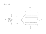
- FIG. 1 is a cross-sectional view showing a primary sealing step according to an exemplary embodiment of the present invention.
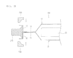
- FIG. 2 is a cross-sectional view showing a folding step according to the exemplary embodiment of the present invention.
- FIG. 3 is a cross-sectional view showing a secondary sealing step according to the exemplary embodiment of the present invention.
- FIG. 4 is a cross-sectional view showing a process of vertically bending the center side of a non-bonded part in the folding step according to the exemplary embodiment of the present invention.
- FIG. 5 is a cross-sectional view showing a process of folding the non-bonded part having the vertically bent center side in the folding step according to the exemplary embodiment of the present invention
- FIG. 1 is a cross-sectional view showing a primary sealing step according to an exemplary embodiment of the present invention
- FIG. 2 is a cross-sectional view showing a folding step according to the exemplary embodiment of the present invention
- FIG. 3 is a cross-sectional view showing a secondary sealing step according to the exemplary embodiment of the present invention
- FIG. 4 is a cross-sectional view showing a process of vertically bending the center side of a non-bonded part 12 in the folding step according to the exemplary embodiment of the present invention
- FIG. 5 is a cross-sectional view showing a process of folding the non-bonded part 12 having the vertically bent center side in the folding step according to the exemplary embodiment of the present invention.
- the present invention relates to a pouch type secondary battery 100 and a method for manufacturing the same, and more particularly, to a pouch type secondary battery 100 capable of preventing corrosion of a metal layer due to exposure of the metal layer to the outside at a distal end of a case thereof and a method for manufacturing the same.
- the pouch type secondary battery 100 includes a pouch type case 10, a sealing part 11 sealed so that an electrolyte injected into the case 10 is not leaked, and non-bonded parts 12 formed by extending the case 10 to an outer side of the sealing part 11, wherein sealing is performed between the non-bonded parts 12 in a state in which the non-bonded parts 12 are folded inwardly.
- the pouch type secondary battery 100 includes a battery assembly 20 provided in the case 10 and the electrolyte injected thereinto, wherein the battery assembly 20 includes an anode, a separator, and a cathode.
- the case 10 may include a metal layer made of a metal such as aluminum, wherein the metal layer may be coated in order to prevent corrosion of the metal layer. In a process of cutting the case 10 as described above, the metal layer is exposed to the outside.
- the sealing is performed one more time in a state in which the distal ends of the non-bonded parts 121 at which the metal layer included in the case 10 is exposed to the outside are folded inwardly, thereby making it possible to prevent the corrosion of the metal layer at the distal end of the case 10 . Therefore, it is possible to prevent dielectric breakdown or moisture penetration due to a local defect or a micro crack generated due to the corrosion of the metal layer at the sealing part 11 and increase sealing strength.
- a method for manufacturing a pouch type secondary battery 100 according to the exemplary embodiment of the present invention includes a primary sealing step, a folding step, and a secondary sealing step.
- the battery assembly 20 including the anode, the separator, and the cathode is inserted into the pouch type case 10 and the electrolyte is then injected into the pouch type case 10.
- the sealing is performed so that the non-bonded parts 12 of the case 10 that are not bonded to each other are formed at an outer side of the sealing part 11 formed by extending the case 10 into which the electrolyte is injected so as to be long and sealed by heat and pressure.
- the non-bonded parts 12 are folded inwardly.
- the case 10 may include a metal layer made of a metal such as aluminum, wherein the metal layer may be coated in order to prevent corrosion of the metal layer.
- the metal layer is exposed to the outside.
- the non-bonded parts 12 are folded inwardly so that the distal end of the case 100 of which the metal layer is exposed to the outside due to the cutting as described above is directed inwardly.
- the metal layer may be coated with a thermoplastic resin such as polyvinyl chloride, polystyrene, polyethylene, polypropylene, acrylic, nylon, or the like.
- the thermoplastic resin may be softened and deformed by being again applied with heat even after being molded through of application of the heat. The heat and the pressure are applied to the cases 10 as described above, thereby making it possible to perform the sealing so that the thermoplastic resin may bond between the cases 10.
- a sealant 30 is inserted into a space between the folded non-bonded parts 12 and the heat is then applied the sealant 30 to seal between the non-bonded parts 12.
- the sealing is secondarily performed after the distal ends of the non-bonded parts 12 at which the metal layer included in the case 10 is exposed to the outside are folded inwardly, thereby making it possible to prevent the corrosion of the metal layer at the distal end of the case 10. Therefore, it is possible to prevent dielectric breakdown or moisture penetration due to a local defect or a micro crack generated due to the corrosion of the metal layer at the sealing part 11 and increase sealing strength.
- the sealant 30 used in the secondary sealing step may be a thermoplastic resin.
- the sealant inserted between the non-bonded parts 12 is used to seal between the non-bonded parts 12 by being melted through the application of the heat, it is preferable that the thermoplastic resin capable of being softened and deformed by being again applied with the heat even after being molded through the application of the heat is used as the sealant 30.
- the thermoplastic resin may be polypropylene, more specifically, a polypropylene tape capable of being easily disposed at a sealing position so that the polypropylene is not out of the sealing position in a sealing process.
- the folding step may include a process of vertically bending the center side of the non-bonded part 12. Since the case 10 of the pouch type secondary battery 100 includes the metal layer, it is not easy to fold the case 10 by a single process. Therefore, it is preferable that the folding step includes the process of bending the center side of the non-bonded part 12 so as to be vertical to an inward direction.
- the non-bonded part 12 may be folded by a first bending jig 210 of which both side surfaces of one end portion are inclined symmetrically to each other so that an area increases, a pressure jig 220, and a second bending jig 230 formed at one end portion of the first bending jig 210 so as to correspond to the first bending jig 210.
- the first bending jig 210 supports an inner side surface of the non-bonded part
- the pressure jig 220 intersects with the first bending jig 210 so as to be in parallel with the first bending jig 210 while pressing an outer side surface of the non-bonded part 12, such that the center side of the non-bonded part 1 2 is vertically bent
- the second bending jig 230 then presses the outer side surface of the non-bonded part 12, thereby making it possible to easily fold the non-bonded part 12.
- the corrosion of the metal layer generated due to the exposure of the metal layer to the outside at the distal end of the case 10 of the pouch type secondary battery 100 is prevented, thereby making it possible to prevent the dielectric breakdown of the pouch type secondary battery 100 or the moisture penetration due to the local defect or the micro crack of the metal layer generated at the sealing part 11 and increase the sealing strength.
- the battery assembly 20 is inserted into the case 10 of the pouch type secondary battery 100, the electrolyte is injected into the case 100, and the heat and the pressure are the applied thereto so that the non-bonded parts 12 are formed at the outer side of the sealing part 11, thereby performing the primary sealing.
- one cross section of the first bending jig 210 having a wide area contacts the inner side surface of the non-bonded part 12.
- the outer side surface of the non-bonded part at a portion that does not contact the one cross section of the first bending jig 210 is pressed using the pressure jig 220 to bend the center side of the non-bonded part 12 so as to be vertical to the inward direction.
- the first bending jig 210 and the pressure jig 220 intersect with each other so as to be parallel with each other.
- the outer side surface of the non-bonded part 12 is pressed using the second bending jig 230 formed corresponding one end portion of the first bending jig 210 so that the non-bonded part 12 is folded.
- the distal end of the non-bonded part 12 subjected to the primary sealing step is folded inwardly as shown in FIG. 2 through the above-mentioned process.
- the sealant 30 is inserted between the folded non-bonded parts 12 and the heat is applied to the sealant 30 to seal between the non-bonded parts 12.
- the corrosion of the metal layer generated due to the exposure of the metal layer to the outside at the distal end of the case of the pouch type secondary battery 100 is prevented thereby making it possible to prevent the dielectric breakdown of the pouch type secondary battery or the moisture penetration due to the local defect or the micro crack of the metal layer generated at the sealing part and increase the sealing strength.
- the present invention is not limited to the above-mentioned exemplary embodiments, and may be variously applied, and may be variously modified without departing from the gist of the present invention claimed in the claim.
Landscapes
- Chemical & Material Sciences (AREA)
- Chemical Kinetics & Catalysis (AREA)
- Electrochemistry (AREA)
- General Chemical & Material Sciences (AREA)
- Engineering & Computer Science (AREA)
- Manufacturing & Machinery (AREA)
- Inorganic Chemistry (AREA)
- Sealing Battery Cases Or Jackets (AREA)
- Secondary Cells (AREA)
Abstract
Description
- This application claims priority under 35 U.S.C. §119 to Korean Patent Application No.
10-2011-0058234, filed on 06,16,2011 - The following disclosure relates to a pouch type secondary battery and a method for manufacturing the same, and more particularly, to a pouch type secondary battery capable of preventing corrosion of a metal layer to exposure of the metal layer to the outside at a distal end of a case thereof, and a method for manufacturing the same.
- Generally, research into a secondary battery capable of being charged and discharged unlike a primary battery has been actively conducted in accordance with the development of state-of-the-art fields such as a. digital camera, a cellular phone, a laptop computer, a hybrid automobile, and the like. An example of the secondary battery includes a nickel-cadmium battery, a nickel-metal hydride battery, a nickel-hydrogen battery, and a lithium secondary battery. Among them, the lithium secondary battery, which has operating voltage of 3.6 V or more, is used as a power supply of a portable electronic device or a plurality of lithium secondary batteries are connected in series with each other to thereby be used for a high output hybrid automobile. Since this lithium secondary battery has operating voltage three times higher than that of the nickel-cadmium battery or the nickel-metal hydride battery and is more excellent in view of energy density characteristics per unit weight than the nickel-cadmium battery or the nickel-metal hydride battery, the use of the lithium secondary battery has rapidly increased.
- The lithium secondary battery may be manufactured in various types. As a typical type of the lithium secondary battery, there are a cylindrical type and a prismatic type that are mainly used for a lithium ion battery. A lithium polymer battery that has been recently spotlighted is manufactured in a pouch type having flexibility, such that it has a relatively free shape.
- In this pouch type lithium polymer battery (hereinafter, referred to as a "pouch type secondary battery"), a battery assembly including an anode, a separator, and a cathode is inserted into a pouch type case, and an electrolyte is injected into the pouch type case, and an edge of the pouch type case is then sealed.
- Generally, the case of the pouch type secondary battery is made of a metal such as aluminum and a material coated in order prevent corrosion of the metal. When this case is subjected to a cutting process, a metal layer of the case is exposed to the outside, such that metal layer may be corroded. In addition, a local defect or a micro crack generated due to the corrosion of the metal layer at a sealing part sealed after the electrolyte is injected into the pouch type case becomes an electrical path to the outside to cause dielectric breakdown of the battery and becomes a moisture penetration path in the battery to significantly deteriorate sealing strength.
- An embodiment of the present invention is directed to providing a. pouch type secondary battery capable of preventing corrosion of a metal layer due to exposure of the metal layer to the outside at a distal end of a case thereof, and a method for manufacturing the same.
- In one general aspect, a pouch type
secondary battery 100 includes: abattery assembly 20 including a plurality of electrodes;cases 10 having an internal space part in which thebattery assembly 20 is received; a sealingpart 11 sealed by applying asealant 30 to a predetermined region of circumferential surfaces of thecases 10 bonded to each other so as to integrate thecases 10 with each other; and non-bondedparts 12 extended from the circumferential surfaces of thecases 10 forming the sealingpart 11. - The center parts of the non-bonded
parts 12 may be folded so that end portions of the non-bondedparts 12 are bonded to each other, the non-bondedparts 12 may be sealed by applying asealant 30 to an outer side of a point at which the non-bonded parts are bonded to each other, and thesealant 30 may be a thermoplastic resin. - In another general aspect, a method for manufacturing a pouch type secondary battery includes: a primary sealing step of applying a
sealant 30 to a predetermined region of circumferential surfaces ofcases 10 bonded to each other so as to integrate thecases 10 with each other to perform sealing, thereby forming a sealingpart 11 and non-bondedparts 12; a folding step of folding the non-bondedparts 12 toward a space therebetween to bond end portions of the non-bondedparts 12 to each other; and a secondary sealing step of inserting thesealant 30 into a point at which the non-bondedparts 12 are folded to be bonded to each other to perform sealing. - The folding step may include a primary folding step of vertically bending the center parts of the non-bonded
parts 12 toward the space between the non-bondedparts 12. - In the primary folding step, a
first bending jig 210 of which both sides of one end portion are inclined symmetrically to each other so that a cross section increases may be inserted into the space between the non-bondedparts 12 to support inner side surfaces of the non-bondedparts 12. - In the primary folding step, a bar
shaped pressure jig 220 may support outer side surfaces of the non-bondedparts 12, and thefirst bending jig 210 and thepressure jig 220 may intersect with each other so as to be in parallel with each other to vertically fold the center parts of the non-bondedparts 12. - The folding step may include a secondary folding step of folding the end portions of the non-bonded
parts 12 vertically folded in the primary folding step so as to be bonded to each other. - In the secondary folding step, the
first bending jig 210 and thepressure jig 220 may intersect with each other so as to be in parallel with each other, and asecond bending jig 230 formed in a shape corresponding to one end portion of thefirst bending jig 210 may press outer side surfaces of the non-bondedparts 12 toward thefirst bending jig 210 to fold the end portions of the non-bondedparts 12 so as to be bonded to each other. -
FIG. 1 is a cross-sectional view showing a primary sealing step according to an exemplary embodiment of the present invention. -
FIG. 2 is a cross-sectional view showing a folding step according to the exemplary embodiment of the present invention. -
FIG. 3 is a cross-sectional view showing a secondary sealing step according to the exemplary embodiment of the present invention. -
FIG. 4 is a cross-sectional view showing a process of vertically bending the center side of a non-bonded part in the folding step according to the exemplary embodiment of the present invention. -
FIG. 5 is a cross-sectional view showing a process of folding the non-bonded part having the vertically bent center side in the folding step according to the exemplary embodiment of the present invention -
- 100: Pouch type secondary battery
- 10: Case
- 11: Sealing part
- 12: Non-bonded part
- 20: Battery assembly
- 30: Sealant
- 210: First bending jig
- 220: Pressure jig
- 230: Second bending jig
- Hereinafter, a technical spirit of the present invention will be described in more detail with reference to the accompanying drawings.
- However, the accompanying drawings are only examples shown in order to describe the technical idea of the present invention in more detail. Therefore, the technical idea of the present invention is not limited to shapes of the accompanying drawings.
-
FIG. 1 is a cross-sectional view showing a primary sealing step according to an exemplary embodiment of the present invention;FIG. 2 is a cross-sectional view showing a folding step according to the exemplary embodiment of the present invention;FIG. 3 is a cross-sectional view showing a secondary sealing step according to the exemplary embodiment of the present invention;FIG. 4 is a cross-sectional view showing a process of vertically bending the center side of anon-bonded part 12 in the folding step according to the exemplary embodiment of the present invention; andFIG. 5 is a cross-sectional view showing a process of folding the non-bondedpart 12 having the vertically bent center side in the folding step according to the exemplary embodiment of the present invention. - The present invention relates to a pouch type
secondary battery 100 and a method for manufacturing the same, and more particularly, to a pouch typesecondary battery 100 capable of preventing corrosion of a metal layer due to exposure of the metal layer to the outside at a distal end of a case thereof and a method for manufacturing the same. - Referring to
FIGS. 1 to 3 , the pouch typesecondary battery 100 according to an exemplary embodiment of the present invention includes apouch type case 10, asealing part 11 sealed so that an electrolyte injected into thecase 10 is not leaked, and non-bondedparts 12 formed by extending thecase 10 to an outer side of the sealingpart 11, wherein sealing is performed between the non-bondedparts 12 in a state in which the non-bondedparts 12 are folded inwardly. - Referring to
FIG. 1 , the pouch typesecondary battery 100 includes abattery assembly 20 provided in thecase 10 and the electrolyte injected thereinto, wherein thebattery assembly 20 includes an anode, a separator, and a cathode. - Although not shown in the accompanying drawings, the
case 10 may include a metal layer made of a metal such as aluminum, wherein the metal layer may be coated in order to prevent corrosion of the metal layer. In a process of cutting thecase 10 as described above, the metal layer is exposed to the outside. - In the pouch type
secondary battery 100 according the exemplary embodiment of the present invention as described above, the sealing is performed one more time in a state in which the distal ends of the non-bonded parts 121 at which the metal layer included in thecase 10 is exposed to the outside are folded inwardly, thereby making it possible to prevent the corrosion of the metal layer at the distal end of thecase 10 . Therefore, it is possible to prevent dielectric breakdown or moisture penetration due to a local defect or a micro crack generated due to the corrosion of the metal layer at the sealingpart 11 and increase sealing strength. - A method for manufacturing a pouch type
secondary battery 100 according to the exemplary embodiment of the present invention includes a primary sealing step, a folding step, and a secondary sealing step. - Referring to
FIG. 1 , in the pouch typesecondary battery 100, thebattery assembly 20 including the anode, the separator, and the cathode is inserted into thepouch type case 10 and the electrolyte is then injected into thepouch type case 10. - Referring to
FIG. 1 , in the primary sealing step of the method for manufacturing a pouch typesecondary battery 100 according to the exemplary embodiment of the present invention, the sealing is performed so that thenon-bonded parts 12 of thecase 10 that are not bonded to each other are formed at an outer side of the sealingpart 11 formed by extending thecase 10 into which the electrolyte is injected so as to be long and sealed by heat and pressure. - Referring to
FIG. 2 , in the folding step, the non-bondedparts 12 are folded inwardly. - Although not shown in the accompanying drawings, the
case 10 may include a metal layer made of a metal such as aluminum, wherein the metal layer may be coated in order to prevent corrosion of the metal layer. In a process of cutting thecase 10 as described above, the metal layer is exposed to the outside. The non-bondedparts 12 are folded inwardly so that the distal end of thecase 100 of which the metal layer is exposed to the outside due to the cutting as described above is directed inwardly. - Here, the metal layer may be coated with a thermoplastic resin such as polyvinyl chloride, polystyrene, polyethylene, polypropylene, acrylic, nylon, or the like. The thermoplastic resin may be softened and deformed by being again applied with heat even after being molded through of application of the heat. The heat and the pressure are applied to the
cases 10 as described above, thereby making it possible to perform the sealing so that the thermoplastic resin may bond between thecases 10. - Referring to
FIG. 3 , in the secondary sealing step, asealant 30 is inserted into a space between the foldednon-bonded parts 12 and the heat is then applied thesealant 30 to seal between thenon-bonded parts 12. - In the method for manufacturing a pouch type
secondary battery 100 according the exemplary embodiment of the present invention as described above, the sealing is secondarily performed after the distal ends of thenon-bonded parts 12 at which the metal layer included in thecase 10 is exposed to the outside are folded inwardly, thereby making it possible to prevent the corrosion of the metal layer at the distal end of thecase 10. Therefore, it is possible to prevent dielectric breakdown or moisture penetration due to a local defect or a micro crack generated due to the corrosion of the metal layer at the sealingpart 11 and increase sealing strength. - The
sealant 30 used in the secondary sealing step may be a thermoplastic resin. - In the secondary scaling step, since the sealant inserted between the
non-bonded parts 12 is used to seal between thenon-bonded parts 12 by being melted through the application of the heat, it is preferable that the thermoplastic resin capable of being softened and deformed by being again applied with the heat even after being molded through the application of the heat is used as thesealant 30. - The thermoplastic resin may be polypropylene, more specifically, a polypropylene tape capable of being easily disposed at a sealing position so that the polypropylene is not out of the sealing position in a sealing process.
- Referring- to
FIG. 4 , the folding step may include a process of vertically bending the center side of thenon-bonded part 12. Since thecase 10 of the pouch typesecondary battery 100 includes the metal layer, it is not easy to fold thecase 10 by a single process. Therefore, it is preferable that the folding step includes the process of bending the center side of thenon-bonded part 12 so as to be vertical to an inward direction. - In the folding step, the
non-bonded part 12 may be folded by afirst bending jig 210 of which both side surfaces of one end portion are inclined symmetrically to each other so that an area increases, apressure jig 220, and asecond bending jig 230 formed at one end portion of thefirst bending jig 210 so as to correspond to thefirst bending jig 210. - Referring to
FIGS , 4 and5 , thefirst bending jig 210 supports an inner side surface of the non-bonded part, thepressure jig 220 intersects with thefirst bending jig 210 so as to be in parallel with thefirst bending jig 210 while pressing an outer side surface of thenon-bonded part 12, such that the center side of the non-bonded part 1 2 is vertically bent, and thesecond bending jig 230 then presses the outer side surface of thenon-bonded part 12, thereby making it possible to easily fold thenon-bonded part 12. - With the pouch type
secondary battery 100 and the method for manufacturing the same as described above, the corrosion of the metal layer generated due to the exposure of the metal layer to the outside at the distal end of thecase 10 of the pouch typesecondary battery 100 is prevented, thereby making it possible to prevent the dielectric breakdown of the pouch typesecondary battery 100 or the moisture penetration due to the local defect or the micro crack of the metal layer generated at the sealingpart 11 and increase the sealing strength. - Hereinafter, the pouch type secondary battery and the method for manufacturing the same according to the exemplary embodiment of the present invention as described above will be described with reference to the accompanying drawings.
- Referring to
FIG. 1 , thebattery assembly 20 is inserted into thecase 10 of the pouch typesecondary battery 100, the electrolyte is injected into thecase 100, and the heat and the pressure are the applied thereto so that thenon-bonded parts 12 are formed at the outer side of the sealingpart 11, thereby performing the primary sealing. - Next, one cross section of the
first bending jig 210 having a wide area contacts the inner side surface of thenon-bonded part 12. Referring toFIG. 4 , the outer side surface of the non-bonded part at a portion that does not contact the one cross section of thefirst bending jig 210 is pressed using thepressure jig 220 to bend the center side of thenon-bonded part 12 so as to be vertical to the inward direction. Here, thefirst bending jig 210 and thepressure jig 220 intersect with each other so as to be parallel with each other. - Referring to
FIG. 5 , when the center side of thenon-bonded part 12 is vertically bent, the outer side surface of thenon-bonded part 12 is pressed using thesecond bending jig 230 formed corresponding one end portion of thefirst bending jig 210 so that thenon-bonded part 12 is folded. - The distal end of the
non-bonded part 12 subjected to the primary sealing step is folded inwardly as shown inFIG. 2 through the above-mentioned process. - Next, as shown in
FIG. 3 thesealant 30 is inserted between the foldednon-bonded parts 12 and the heat is applied to thesealant 30 to seal between thenon-bonded parts 12. - As set forth above, with the pouch type secondary battery and the method for manufacturing the same according to the exemplary embodiment of the present invention, the corrosion of the metal layer generated due to the exposure of the metal layer to the outside at the distal end of the case of the pouch type
secondary battery 100 is prevented thereby making it possible to prevent the dielectric breakdown of the pouch type secondary battery or the moisture penetration due to the local defect or the micro crack of the metal layer generated at the sealing part and increase the sealing strength. - The present invention is not limited to the above-mentioned exemplary embodiments, and may be variously applied, and may be variously modified without departing from the gist of the present invention claimed in the claim.
Claims (10)
- A pouch type secondary battery comprising:a battery assembly including a plurality of electrodes;cases having an internal space part in which the battery assembly is received;a sealing part sealed by applying a sealant to a predetermined region of circumferential surfaces of the cases bonded to each other so as to integrate the cases with each other; andnon-bonded parts extended from the circumferential surfaces of the cases forming the sealing part.
- The pouch type secondary battery of claim 1, wherein the center parts of the non-bonded parts are folded so that end portions of the non-bonded parts are bonded to each other.
- The pouch type secondary battery of claim 2, wherein the non-bonded parts are sealed by applying the sealant to an outer side of a point at which the non-bonded parts are bonded to each other.
- The pouch type secondary battery of claim 1, wherein the sealant is a thermoplastic resin.
- A method for manufacturing a pouch type secondary battery, the method comprising:a primary sealing step of applying a sealant to a predetermined region of circumferential surfaces of cases bonded to each other so as to integrate the cases with each other to perform sealing, thereby forming a sealing part and non-bonded parts;a folding step of folding the non-bonded parts toward a space therebetween to bond end portions of the non-bonded parts to each other; anda secondary sealing step of inserting the sealant into a point at which the non-bonded parts are folded to be bonded to each other to perform sealing.
- The method of claim 5, wherein the folding step includes a primary folding step of vertically bending the center parts of the non-bonded parts toward the space between the non--bonded parts.
- The method of claim 6, wherein in the primary folding step, a first bending jig of which both sides of one end portion are inclined symmetrically to each other so that a cross section increases is inserted into the space between the non-bonded parts to support inner side surfaces of the non-bonded parts.
- The method of claim 7, wherein in the primary folding step, a bar shaped pressure jig supports outer side surfaces of the non-bonded parts, and the first bending jig and the pressure jig intersect with each other so as to be in parallel with each other to vertically fold she center parts of the non-bonded parts.
- The method of claim 6, wherein the folding step includes a secondary folding step of folding the end portions of the non-bonded parts vertically folded in the primary folding step so as to be bonded to each other.
- The method of claim 9, wherein in the secondary folding step, the first bending jig and the pressure jig intersect with each other so as to be in parallel with each other, and a second bending jig formed in a shape corresponding to one end portion of the first bending jig presses outer side surfaces of the non-bonded parts toward the first bending jig to fold the end portions of the non-bonded parts so as to be bonded to each other.
Applications Claiming Priority (1)
| Application Number | Priority Date | Filing Date | Title |
|---|---|---|---|
| KR20110058234A KR101371040B1 (en) | 2011-06-16 | 2011-06-16 | Pouch type secondary battery and methods for producing it |
Publications (2)
| Publication Number | Publication Date |
|---|---|
| EP2535961A1 true EP2535961A1 (en) | 2012-12-19 |
| EP2535961B1 EP2535961B1 (en) | 2013-12-25 |
Family
ID=46317200
Family Applications (1)
| Application Number | Title | Priority Date | Filing Date |
|---|---|---|---|
| EP20120172016 Active EP2535961B1 (en) | 2011-06-16 | 2012-06-14 | Pouch type secondary battery and method for manufacturing the same |
Country Status (5)
| Country | Link |
|---|---|
| US (2) | US20120321935A1 (en) |
| EP (1) | EP2535961B1 (en) |
| JP (1) | JP5690308B2 (en) |
| KR (1) | KR101371040B1 (en) |
| CN (1) | CN102832357B (en) |
Cited By (1)
| Publication number | Priority date | Publication date | Assignee | Title |
|---|---|---|---|---|
| EP3236509A1 (en) * | 2016-04-19 | 2017-10-25 | Ningde Amperex Technology Limited | Method of edge sealing for secondary lithium battery |
Families Citing this family (19)
| Publication number | Priority date | Publication date | Assignee | Title |
|---|---|---|---|---|
| KR101661562B1 (en) * | 2013-06-18 | 2016-10-04 | 주식회사 엘지화학 | a secondary battery sealing by sealant |
| KR102106445B1 (en) * | 2013-08-28 | 2020-05-04 | 삼성에스디아이 주식회사 | Wireless communication device AND METHOD FOR SERVING POWER THEREOF |
| KR20150030861A (en) * | 2013-09-13 | 2015-03-23 | 주식회사 엘지화학 | Pouched type case, battery cell and manufacturing method of battery cell |
| JP6032233B2 (en) * | 2014-03-18 | 2016-11-24 | トヨタ自動車株式会社 | Solid battery and manufacturing method thereof, and assembled battery and manufacturing method thereof |
| CN108140753B (en) * | 2015-10-16 | 2021-09-07 | 罗伯特·博世有限公司 | Deep profile pockets for battery cells |
| KR102119183B1 (en) * | 2016-08-18 | 2020-06-04 | 주식회사 엘지화학 | Battery module |
| KR102016643B1 (en) * | 2016-09-19 | 2019-08-30 | 주식회사 엘지화학 | Rechargeable battery |
| EP3373374B1 (en) * | 2016-09-28 | 2019-09-11 | LG Chem, Ltd. | Method for sealing pouch case of secondary battery |
| KR102347884B1 (en) * | 2017-10-17 | 2022-01-06 | 주식회사 엘지에너지솔루션 | Sealing Block to Prevent Crack of Pouch-Type Secondary Battery, Pouch-Type Battery Case and Sealing Method for Pouch-Type Battery Case Using thereof |
| KR102789780B1 (en) * | 2020-01-06 | 2025-04-04 | 주식회사 엘지에너지솔루션 | Secondary battery, battery pack and device for manufacturing secondary battery |
| JP7437609B2 (en) * | 2020-04-02 | 2024-02-26 | トヨタ自動車株式会社 | Laminated power storage device and its short circuit inspection method |
| KR102747620B1 (en) * | 2020-04-20 | 2024-12-31 | 주식회사 엘지에너지솔루션 | Secondary battery and manufacturing method thereof |
| KR102883723B1 (en) * | 2020-07-27 | 2025-11-11 | 에스케이온 주식회사 | Pouch-type secondary battery and method for manufacturing thereof |
| WO2022039536A1 (en) | 2020-08-19 | 2022-02-24 | 주식회사 엘지에너지솔루션 | Pouch type battery case and pouch type secondary battery |
| EP4184670A4 (en) * | 2020-08-19 | 2024-12-25 | LG Energy Solution, Ltd. | POCKET TYPE RECHARGEABLE BATTERY |
| WO2022098094A1 (en) * | 2020-11-03 | 2022-05-12 | 주식회사 엘지에너지솔루션 | Apparatus for folding pouch |
| KR102789779B1 (en) * | 2021-06-02 | 2025-04-04 | 주식회사 엘지에너지솔루션 | Sealing tool and electrode assembly manufactured by the same |
| CN113871808B (en) * | 2021-10-25 | 2024-03-26 | 珠海冠宇电池股份有限公司 | Soft package lithium ion battery and electronic device |
| WO2025147184A1 (en) * | 2024-01-05 | 2025-07-10 | 주식회사 엘지에너지솔루션 | Pouch-type secondary battery, pouch sealing device, and sealing method using same |
Citations (3)
| Publication number | Priority date | Publication date | Assignee | Title |
|---|---|---|---|---|
| EP0397248A2 (en) * | 1989-05-08 | 1990-11-14 | Eastman Kodak Company | Electrochemical cell modules |
| EP0973212A1 (en) * | 1997-03-19 | 2000-01-19 | Asahi Kasei Kogyo Kabushiki Kaisha | Nonaqueous thin battery |
| EP1276161A1 (en) * | 2000-04-19 | 2003-01-15 | Dai Nippon Printing Co., Ltd. | Battery, tab of battery and method of manufacture thereof |
Family Cites Families (13)
| Publication number | Priority date | Publication date | Assignee | Title |
|---|---|---|---|---|
| JP3017760B2 (en) * | 1989-11-30 | 2000-03-13 | ソニー株式会社 | Paper battery |
| JP2001283799A (en) * | 2000-03-30 | 2001-10-12 | Sony Corp | Battery manufacturing method and folding device used therefor |
| JP2001334331A (en) * | 2000-05-22 | 2001-12-04 | Toshiba Electronic Engineering Corp | Bending method of thin plate and method of manufacturing sealed secondary battery |
| JP2002331309A (en) * | 2001-05-09 | 2002-11-19 | Toshiba Electronic Engineering Corp | Bending method of thin plate, mold and method of manufacturing sealed secondary battery |
| JP2004055154A (en) | 2002-07-16 | 2004-02-19 | Nissan Motor Co Ltd | Sealing structure and sealing treatment method for stacked battery |
| JP4085741B2 (en) * | 2002-08-21 | 2008-05-14 | 日産自動車株式会社 | Single cell, battery module and battery pack |
| KR20040054128A (en) * | 2002-12-17 | 2004-06-25 | 삼성에스디아이 주식회사 | Pouched-type lithium secondary battery |
| JP2005116329A (en) * | 2003-10-07 | 2005-04-28 | Sony Corp | Battery manufacturing apparatus and battery manufacturing method |
| KR100878703B1 (en) * | 2005-11-28 | 2009-01-14 | 주식회사 엘지화학 | Small battery pack with PCM in side sealing part |
| KR100879893B1 (en) * | 2006-07-10 | 2009-01-21 | 주식회사 엘지화학 | Secondary battery with improved safety |
| KR100884474B1 (en) * | 2007-04-02 | 2009-02-20 | 삼성에스디아이 주식회사 | Pouch type secondary battery and manufacturing method thereof |
| JP5303974B2 (en) * | 2008-03-14 | 2013-10-02 | 日本電気株式会社 | Assembled battery |
| KR101002468B1 (en) * | 2008-07-01 | 2010-12-17 | 삼성에스디아이 주식회사 | Pouch Type Lithium Secondary Battery |
-
2011
- 2011-06-16 KR KR20110058234A patent/KR101371040B1/en active Active
-
2012
- 2012-06-14 EP EP20120172016 patent/EP2535961B1/en active Active
- 2012-06-14 JP JP2012134430A patent/JP5690308B2/en active Active
- 2012-06-15 US US13/524,299 patent/US20120321935A1/en not_active Abandoned
- 2012-06-18 CN CN201210205723.6A patent/CN102832357B/en active Active
-
2013
- 2013-07-12 US US13/940,549 patent/US9070947B2/en active Active
Patent Citations (3)
| Publication number | Priority date | Publication date | Assignee | Title |
|---|---|---|---|---|
| EP0397248A2 (en) * | 1989-05-08 | 1990-11-14 | Eastman Kodak Company | Electrochemical cell modules |
| EP0973212A1 (en) * | 1997-03-19 | 2000-01-19 | Asahi Kasei Kogyo Kabushiki Kaisha | Nonaqueous thin battery |
| EP1276161A1 (en) * | 2000-04-19 | 2003-01-15 | Dai Nippon Printing Co., Ltd. | Battery, tab of battery and method of manufacture thereof |
Cited By (2)
| Publication number | Priority date | Publication date | Assignee | Title |
|---|---|---|---|---|
| EP3236509A1 (en) * | 2016-04-19 | 2017-10-25 | Ningde Amperex Technology Limited | Method of edge sealing for secondary lithium battery |
| US10166723B2 (en) | 2016-04-19 | 2019-01-01 | Ningde Amperex Technology Limited | Method of edge sealing for secondary lithium battery |
Also Published As
| Publication number | Publication date |
|---|---|
| EP2535961B1 (en) | 2013-12-25 |
| KR20120138848A (en) | 2012-12-27 |
| US20130298388A1 (en) | 2013-11-14 |
| KR101371040B1 (en) | 2014-03-10 |
| CN102832357B (en) | 2014-09-17 |
| CN102832357A (en) | 2012-12-19 |
| JP2013004525A (en) | 2013-01-07 |
| JP5690308B2 (en) | 2015-03-25 |
| US20120321935A1 (en) | 2012-12-20 |
| US9070947B2 (en) | 2015-06-30 |
Similar Documents
| Publication | Publication Date | Title |
|---|---|---|
| EP2535961B1 (en) | Pouch type secondary battery and method for manufacturing the same | |
| US20250096278A1 (en) | Rectangular secondary battery and method of manufacturing the same | |
| EP4057438A1 (en) | Electrode tab bending apparatus and method | |
| US10062871B2 (en) | Rechargeable battery with tabs | |
| JP5600078B2 (en) | Pouch type secondary battery and manufacturing method thereof | |
| EP2312669A1 (en) | Secondary battery and method of manufacturing the same | |
| US11923558B2 (en) | Rectangular secondary battery | |
| KR20110124269A (en) | Button batteries and how to make them | |
| JP6963773B2 (en) | Coin-type battery and its manufacturing method | |
| EP3107134B1 (en) | Rechargeable battery module | |
| JP7213250B2 (en) | Coin-shaped battery and its manufacturing method | |
| US20160141711A1 (en) | Method of manufacturing rechargeable battery with curved surface | |
| CN113875043B (en) | Secondary battery | |
| US10854856B2 (en) | Curved secondary battery | |
| KR20230151375A (en) | Secondary battery and manufacturing method of the same | |
| KR20160026259A (en) | Method for Manufacturing Secondary Battery | |
| US9620748B2 (en) | Rechargeable battery | |
| EP4201651B1 (en) | Apparatus for sealing battery case, and secondary battery manufactured using same | |
| EP1701398A1 (en) | Rechargeable battery and method of assembling for the same | |
| KR101584301B1 (en) | Method for manufacturing electrode tab and method for manufacturing electrode lead | |
| KR20220014837A (en) | Button type secondary battery and manufacturing method thereof | |
| KR20210037460A (en) | The Battery Case For Secondary Battery And The Method For Manufacturing Thereof | |
| KR20210038237A (en) | The Method For Manufacturing Pouch Type Secondary Battery | |
| KR102887618B1 (en) | Secondary Battery | |
| KR102833816B1 (en) | The Electrode Lead, The Method For Manufacturing Thereof And The Pouch Type Secondary Battery |
Legal Events
| Date | Code | Title | Description |
|---|---|---|---|
| PUAI | Public reference made under article 153(3) epc to a published international application that has entered the european phase |
Free format text: ORIGINAL CODE: 0009012 |
|
| AK | Designated contracting states |
Kind code of ref document: A1 Designated state(s): AL AT BE BG CH CY CZ DE DK EE ES FI FR GB GR HR HU IE IS IT LI LT LU LV MC MK MT NL NO PL PT RO RS SE SI SK SM TR |
|
| AX | Request for extension of the european patent |
Extension state: BA ME |
|
| GRAP | Despatch of communication of intention to grant a patent |
Free format text: ORIGINAL CODE: EPIDOSNIGR1 |
|
| 17P | Request for examination filed |
Effective date: 20130614 |
|
| RBV | Designated contracting states (corrected) |
Designated state(s): AL AT BE BG CH CY CZ DE DK EE ES FI FR GB GR HR HU IE IS IT LI LT LU LV MC MK MT NL NO PL PT RO RS SE SI SK SM TR |
|
| RIC1 | Information provided on ipc code assigned before grant |
Ipc: H01M 10/05 20100101ALI20130711BHEP Ipc: H01M 2/02 20060101AFI20130711BHEP |
|
| INTG | Intention to grant announced |
Effective date: 20130726 |
|
| GRAS | Grant fee paid |
Free format text: ORIGINAL CODE: EPIDOSNIGR3 |
|
| GRAA | (expected) grant |
Free format text: ORIGINAL CODE: 0009210 |
|
| AK | Designated contracting states |
Kind code of ref document: B1 Designated state(s): AL AT BE BG CH CY CZ DE DK EE ES FI FR GB GR HR HU IE IS IT LI LT LU LV MC MK MT NL NO PL PT RO RS SE SI SK SM TR |
|
| REG | Reference to a national code |
Ref country code: GB Ref legal event code: FG4D |
|
| REG | Reference to a national code |
Ref country code: CH Ref legal event code: EP |
|
| REG | Reference to a national code |
Ref country code: AT Ref legal event code: REF Ref document number: 647002 Country of ref document: AT Kind code of ref document: T Effective date: 20140115 |
|
| REG | Reference to a national code |
Ref country code: IE Ref legal event code: FG4D |
|
| REG | Reference to a national code |
Ref country code: DE Ref legal event code: R096 Ref document number: 602012000707 Country of ref document: DE Effective date: 20140213 |
|
| PG25 | Lapsed in a contracting state [announced via postgrant information from national office to epo] |
Ref country code: FI Free format text: LAPSE BECAUSE OF FAILURE TO SUBMIT A TRANSLATION OF THE DESCRIPTION OR TO PAY THE FEE WITHIN THE PRESCRIBED TIME-LIMIT Effective date: 20131225 Ref country code: LT Free format text: LAPSE BECAUSE OF FAILURE TO SUBMIT A TRANSLATION OF THE DESCRIPTION OR TO PAY THE FEE WITHIN THE PRESCRIBED TIME-LIMIT Effective date: 20131225 Ref country code: SE Free format text: LAPSE BECAUSE OF FAILURE TO SUBMIT A TRANSLATION OF THE DESCRIPTION OR TO PAY THE FEE WITHIN THE PRESCRIBED TIME-LIMIT Effective date: 20131225 Ref country code: HR Free format text: LAPSE BECAUSE OF FAILURE TO SUBMIT A TRANSLATION OF THE DESCRIPTION OR TO PAY THE FEE WITHIN THE PRESCRIBED TIME-LIMIT Effective date: 20131225 Ref country code: NO Free format text: LAPSE BECAUSE OF FAILURE TO SUBMIT A TRANSLATION OF THE DESCRIPTION OR TO PAY THE FEE WITHIN THE PRESCRIBED TIME-LIMIT Effective date: 20140325 |
|
| REG | Reference to a national code |
Ref country code: NL Ref legal event code: VDEP Effective date: 20131225 |
|
| REG | Reference to a national code |
Ref country code: AT Ref legal event code: MK05 Ref document number: 647002 Country of ref document: AT Kind code of ref document: T Effective date: 20131225 |
|
| REG | Reference to a national code |
Ref country code: LT Ref legal event code: MG4D |
|
| PG25 | Lapsed in a contracting state [announced via postgrant information from national office to epo] |
Ref country code: LV Free format text: LAPSE BECAUSE OF FAILURE TO SUBMIT A TRANSLATION OF THE DESCRIPTION OR TO PAY THE FEE WITHIN THE PRESCRIBED TIME-LIMIT Effective date: 20131225 Ref country code: RS Free format text: LAPSE BECAUSE OF FAILURE TO SUBMIT A TRANSLATION OF THE DESCRIPTION OR TO PAY THE FEE WITHIN THE PRESCRIBED TIME-LIMIT Effective date: 20131225 |
|
| PG25 | Lapsed in a contracting state [announced via postgrant information from national office to epo] |
Ref country code: EE Free format text: LAPSE BECAUSE OF FAILURE TO SUBMIT A TRANSLATION OF THE DESCRIPTION OR TO PAY THE FEE WITHIN THE PRESCRIBED TIME-LIMIT Effective date: 20131225 Ref country code: IS Free format text: LAPSE BECAUSE OF FAILURE TO SUBMIT A TRANSLATION OF THE DESCRIPTION OR TO PAY THE FEE WITHIN THE PRESCRIBED TIME-LIMIT Effective date: 20140425 Ref country code: BE Free format text: LAPSE BECAUSE OF FAILURE TO SUBMIT A TRANSLATION OF THE DESCRIPTION OR TO PAY THE FEE WITHIN THE PRESCRIBED TIME-LIMIT Effective date: 20131225 |
|
| PG25 | Lapsed in a contracting state [announced via postgrant information from national office to epo] |
Ref country code: CZ Free format text: LAPSE BECAUSE OF FAILURE TO SUBMIT A TRANSLATION OF THE DESCRIPTION OR TO PAY THE FEE WITHIN THE PRESCRIBED TIME-LIMIT Effective date: 20131225 Ref country code: AT Free format text: LAPSE BECAUSE OF FAILURE TO SUBMIT A TRANSLATION OF THE DESCRIPTION OR TO PAY THE FEE WITHIN THE PRESCRIBED TIME-LIMIT Effective date: 20131225 Ref country code: SK Free format text: LAPSE BECAUSE OF FAILURE TO SUBMIT A TRANSLATION OF THE DESCRIPTION OR TO PAY THE FEE WITHIN THE PRESCRIBED TIME-LIMIT Effective date: 20131225 Ref country code: RO Free format text: LAPSE BECAUSE OF FAILURE TO SUBMIT A TRANSLATION OF THE DESCRIPTION OR TO PAY THE FEE WITHIN THE PRESCRIBED TIME-LIMIT Effective date: 20131225 Ref country code: NL Free format text: LAPSE BECAUSE OF FAILURE TO SUBMIT A TRANSLATION OF THE DESCRIPTION OR TO PAY THE FEE WITHIN THE PRESCRIBED TIME-LIMIT Effective date: 20131225 Ref country code: ES Free format text: LAPSE BECAUSE OF FAILURE TO SUBMIT A TRANSLATION OF THE DESCRIPTION OR TO PAY THE FEE WITHIN THE PRESCRIBED TIME-LIMIT Effective date: 20131225 Ref country code: PT Free format text: LAPSE BECAUSE OF FAILURE TO SUBMIT A TRANSLATION OF THE DESCRIPTION OR TO PAY THE FEE WITHIN THE PRESCRIBED TIME-LIMIT Effective date: 20140428 Ref country code: CY Free format text: LAPSE BECAUSE OF FAILURE TO SUBMIT A TRANSLATION OF THE DESCRIPTION OR TO PAY THE FEE WITHIN THE PRESCRIBED TIME-LIMIT Effective date: 20131225 |
|
| REG | Reference to a national code |
Ref country code: DE Ref legal event code: R097 Ref document number: 602012000707 Country of ref document: DE |
|
| PG25 | Lapsed in a contracting state [announced via postgrant information from national office to epo] |
Ref country code: DK Free format text: LAPSE BECAUSE OF FAILURE TO SUBMIT A TRANSLATION OF THE DESCRIPTION OR TO PAY THE FEE WITHIN THE PRESCRIBED TIME-LIMIT Effective date: 20131225 |
|
| PLBE | No opposition filed within time limit |
Free format text: ORIGINAL CODE: 0009261 |
|
| STAA | Information on the status of an ep patent application or granted ep patent |
Free format text: STATUS: NO OPPOSITION FILED WITHIN TIME LIMIT |
|
| PG25 | Lapsed in a contracting state [announced via postgrant information from national office to epo] |
Ref country code: PL Free format text: LAPSE BECAUSE OF FAILURE TO SUBMIT A TRANSLATION OF THE DESCRIPTION OR TO PAY THE FEE WITHIN THE PRESCRIBED TIME-LIMIT Effective date: 20131225 |
|
| 26N | No opposition filed |
Effective date: 20140926 |
|
| REG | Reference to a national code |
Ref country code: DE Ref legal event code: R097 Ref document number: 602012000707 Country of ref document: DE Effective date: 20140926 |
|
| PG25 | Lapsed in a contracting state [announced via postgrant information from national office to epo] |
Ref country code: LU Free format text: LAPSE BECAUSE OF FAILURE TO SUBMIT A TRANSLATION OF THE DESCRIPTION OR TO PAY THE FEE WITHIN THE PRESCRIBED TIME-LIMIT Effective date: 20140614 Ref country code: MC Free format text: LAPSE BECAUSE OF FAILURE TO SUBMIT A TRANSLATION OF THE DESCRIPTION OR TO PAY THE FEE WITHIN THE PRESCRIBED TIME-LIMIT Effective date: 20131225 |
|
| REG | Reference to a national code |
Ref country code: IE Ref legal event code: MM4A |
|
| REG | Reference to a national code |
Ref country code: FR Ref legal event code: PLFP Year of fee payment: 4 |
|
| PG25 | Lapsed in a contracting state [announced via postgrant information from national office to epo] |
Ref country code: IE Free format text: LAPSE BECAUSE OF NON-PAYMENT OF DUE FEES Effective date: 20140614 |
|
| PG25 | Lapsed in a contracting state [announced via postgrant information from national office to epo] |
Ref country code: SI Free format text: LAPSE BECAUSE OF FAILURE TO SUBMIT A TRANSLATION OF THE DESCRIPTION OR TO PAY THE FEE WITHIN THE PRESCRIBED TIME-LIMIT Effective date: 20131225 |
|
| REG | Reference to a national code |
Ref country code: CH Ref legal event code: PL |
|
| PG25 | Lapsed in a contracting state [announced via postgrant information from national office to epo] |
Ref country code: MT Free format text: LAPSE BECAUSE OF FAILURE TO SUBMIT A TRANSLATION OF THE DESCRIPTION OR TO PAY THE FEE WITHIN THE PRESCRIBED TIME-LIMIT Effective date: 20131225 |
|
| REG | Reference to a national code |
Ref country code: FR Ref legal event code: PLFP Year of fee payment: 5 |
|
| PG25 | Lapsed in a contracting state [announced via postgrant information from national office to epo] |
Ref country code: LI Free format text: LAPSE BECAUSE OF NON-PAYMENT OF DUE FEES Effective date: 20150630 Ref country code: SM Free format text: LAPSE BECAUSE OF FAILURE TO SUBMIT A TRANSLATION OF THE DESCRIPTION OR TO PAY THE FEE WITHIN THE PRESCRIBED TIME-LIMIT Effective date: 20131225 Ref country code: CH Free format text: LAPSE BECAUSE OF NON-PAYMENT OF DUE FEES Effective date: 20150630 |
|
| PG25 | Lapsed in a contracting state [announced via postgrant information from national office to epo] |
Ref country code: BG Free format text: LAPSE BECAUSE OF FAILURE TO SUBMIT A TRANSLATION OF THE DESCRIPTION OR TO PAY THE FEE WITHIN THE PRESCRIBED TIME-LIMIT Effective date: 20131225 Ref country code: GR Free format text: LAPSE BECAUSE OF FAILURE TO SUBMIT A TRANSLATION OF THE DESCRIPTION OR TO PAY THE FEE WITHIN THE PRESCRIBED TIME-LIMIT Effective date: 20140326 |
|
| PG25 | Lapsed in a contracting state [announced via postgrant information from national office to epo] |
Ref country code: HU Free format text: LAPSE BECAUSE OF FAILURE TO SUBMIT A TRANSLATION OF THE DESCRIPTION OR TO PAY THE FEE WITHIN THE PRESCRIBED TIME-LIMIT; INVALID AB INITIO Effective date: 20120614 Ref country code: TR Free format text: LAPSE BECAUSE OF FAILURE TO SUBMIT A TRANSLATION OF THE DESCRIPTION OR TO PAY THE FEE WITHIN THE PRESCRIBED TIME-LIMIT Effective date: 20131225 |
|
| GBPC | Gb: european patent ceased through non-payment of renewal fee |
Effective date: 20160614 |
|
| REG | Reference to a national code |
Ref country code: FR Ref legal event code: PLFP Year of fee payment: 6 |
|
| PG25 | Lapsed in a contracting state [announced via postgrant information from national office to epo] |
Ref country code: GB Free format text: LAPSE BECAUSE OF NON-PAYMENT OF DUE FEES Effective date: 20160614 |
|
| REG | Reference to a national code |
Ref country code: FR Ref legal event code: PLFP Year of fee payment: 7 |
|
| PG25 | Lapsed in a contracting state [announced via postgrant information from national office to epo] |
Ref country code: MK Free format text: LAPSE BECAUSE OF FAILURE TO SUBMIT A TRANSLATION OF THE DESCRIPTION OR TO PAY THE FEE WITHIN THE PRESCRIBED TIME-LIMIT Effective date: 20131225 |
|
| PG25 | Lapsed in a contracting state [announced via postgrant information from national office to epo] |
Ref country code: AL Free format text: LAPSE BECAUSE OF FAILURE TO SUBMIT A TRANSLATION OF THE DESCRIPTION OR TO PAY THE FEE WITHIN THE PRESCRIBED TIME-LIMIT Effective date: 20131225 |
|
| REG | Reference to a national code |
Ref country code: DE Ref legal event code: R079 Ref document number: 602012000707 Country of ref document: DE Free format text: PREVIOUS MAIN CLASS: H01M0002020000 Ipc: H01M0050100000 |
|
| REG | Reference to a national code |
Ref country code: DE Ref legal event code: R081 Ref document number: 602012000707 Country of ref document: DE Owner name: SK ON CO., LTD., KR Free format text: FORMER OWNER: SK INNOVATION CO., LTD., SEOUL, KR |
|
| P01 | Opt-out of the competence of the unified patent court (upc) registered |
Effective date: 20230602 |
|
| PGFP | Annual fee paid to national office [announced via postgrant information from national office to epo] |
Ref country code: IT Payment date: 20250321 Year of fee payment: 14 |
|
| PGFP | Annual fee paid to national office [announced via postgrant information from national office to epo] |
Ref country code: DE Payment date: 20250320 Year of fee payment: 14 |
|
| PGFP | Annual fee paid to national office [announced via postgrant information from national office to epo] |
Ref country code: FR Payment date: 20260323 Year of fee payment: 15 |