EP2535727A1 - Energy display system - Google Patents
Energy display system Download PDFInfo
- Publication number
- EP2535727A1 EP2535727A1 EP11739789A EP11739789A EP2535727A1 EP 2535727 A1 EP2535727 A1 EP 2535727A1 EP 11739789 A EP11739789 A EP 11739789A EP 11739789 A EP11739789 A EP 11739789A EP 2535727 A1 EP2535727 A1 EP 2535727A1
- Authority
- EP
- European Patent Office
- Prior art keywords
- power
- electric
- electric power
- power consumption
- display
- Prior art date
- Legal status (The legal status is an assumption and is not a legal conclusion. Google has not performed a legal analysis and makes no representation as to the accuracy of the status listed.)
- Withdrawn
Links
Images


Classifications
-
- G—PHYSICS
- G01—MEASURING; TESTING
- G01R—MEASURING ELECTRIC VARIABLES; MEASURING MAGNETIC VARIABLES
- G01R22/00—Arrangements for measuring time integral of electric power or current, e.g. electricity meters
- G01R22/06—Arrangements for measuring time integral of electric power or current, e.g. electricity meters by electronic methods
- G01R22/10—Arrangements for measuring time integral of electric power or current, e.g. electricity meters by electronic methods using digital techniques
-
- H—ELECTRICITY
- H02—GENERATION; CONVERSION OR DISTRIBUTION OF ELECTRIC POWER
- H02J—ELECTRIC POWER NETWORKS; CIRCUIT ARRANGEMENTS OR SYSTEMS FOR SUPPLYING OR DISTRIBUTING ELECTRIC POWER; SYSTEMS FOR STORING ELECTRIC ENERGY
- H02J13/00—Circuit arrangements for providing remote monitoring or remote control of equipment in a power distribution network
- H02J13/10—Circuit arrangements for providing remote monitoring or remote control of equipment in a power distribution network characterised by displaying of information or by user interaction, e.g. supervisory control and data acquisition [SCADA] systems
-
- H—ELECTRICITY
- H02—GENERATION; CONVERSION OR DISTRIBUTION OF ELECTRIC POWER
- H02J—ELECTRIC POWER NETWORKS; CIRCUIT ARRANGEMENTS OR SYSTEMS FOR SUPPLYING OR DISTRIBUTING ELECTRIC POWER; SYSTEMS FOR STORING ELECTRIC ENERGY
- H02J13/00—Circuit arrangements for providing remote monitoring or remote control of equipment in a power distribution network
- H02J13/18—Circuit arrangements for providing remote monitoring or remote control of equipment in a power distribution network characterised by the remotely-controlled equipment, e.g. converters or transformers
- H02J13/333—Circuit arrangements for providing remote monitoring or remote control of equipment in a power distribution network characterised by the remotely-controlled equipment, e.g. converters or transformers the equipment forming part of substations
-
- H—ELECTRICITY
- H02—GENERATION; CONVERSION OR DISTRIBUTION OF ELECTRIC POWER
- H02J—ELECTRIC POWER NETWORKS; CIRCUIT ARRANGEMENTS OR SYSTEMS FOR SUPPLYING OR DISTRIBUTING ELECTRIC POWER; SYSTEMS FOR STORING ELECTRIC ENERGY
- H02J3/00—Circuit arrangements for AC mains or AC distribution networks
- H02J3/38—Arrangements for feeding a single network from two or more generators or sources in parallel; Arrangements for feeding already energised networks from additional generators or sources in parallel
- H02J3/381—Dispersed generators
-
- G—PHYSICS
- G01—MEASURING; TESTING
- G01D—MEASURING NOT SPECIALLY ADAPTED FOR A SPECIFIC VARIABLE; ARRANGEMENTS FOR MEASURING TWO OR MORE VARIABLES NOT COVERED IN A SINGLE OTHER SUBCLASS; TARIFF METERING APPARATUS; MEASURING OR TESTING NOT OTHERWISE PROVIDED FOR
- G01D2204/00—Indexing scheme relating to details of tariff-metering apparatus
- G01D2204/10—Analysing; Displaying
- G01D2204/18—Remote displaying of utility meter readings
-
- G—PHYSICS
- G01—MEASURING; TESTING
- G01D—MEASURING NOT SPECIALLY ADAPTED FOR A SPECIFIC VARIABLE; ARRANGEMENTS FOR MEASURING TWO OR MORE VARIABLES NOT COVERED IN A SINGLE OTHER SUBCLASS; TARIFF METERING APPARATUS; MEASURING OR TESTING NOT OTHERWISE PROVIDED FOR
- G01D2204/00—Indexing scheme relating to details of tariff-metering apparatus
- G01D2204/30—Remote utility meter reading systems specially adapted for metering the generated energy or power
- G01D2204/35—Monitoring the performance of renewable electricity generating systems, e.g. of solar panels
-
- H—ELECTRICITY
- H02—GENERATION; CONVERSION OR DISTRIBUTION OF ELECTRIC POWER
- H02J—ELECTRIC POWER NETWORKS; CIRCUIT ARRANGEMENTS OR SYSTEMS FOR SUPPLYING OR DISTRIBUTING ELECTRIC POWER; SYSTEMS FOR STORING ELECTRIC ENERGY
- H02J2101/00—Supply or distribution of decentralised, dispersed or local electric power generation
- H02J2101/20—Dispersed power generation using renewable energy sources
- H02J2101/22—Solar energy
- H02J2101/24—Photovoltaics
-
- H—ELECTRICITY
- H02—GENERATION; CONVERSION OR DISTRIBUTION OF ELECTRIC POWER
- H02J—ELECTRIC POWER NETWORKS; CIRCUIT ARRANGEMENTS OR SYSTEMS FOR SUPPLYING OR DISTRIBUTING ELECTRIC POWER; SYSTEMS FOR STORING ELECTRIC ENERGY
- H02J7/00—Circuit arrangements for charging or discharging batteries or for supplying loads from batteries
- H02J7/80—Circuit arrangements for charging or discharging batteries or for supplying loads from batteries including monitoring or indicating arrangements
-
- Y—GENERAL TAGGING OF NEW TECHNOLOGICAL DEVELOPMENTS; GENERAL TAGGING OF CROSS-SECTIONAL TECHNOLOGIES SPANNING OVER SEVERAL SECTIONS OF THE IPC; TECHNICAL SUBJECTS COVERED BY FORMER USPC CROSS-REFERENCE ART COLLECTIONS [XRACs] AND DIGESTS
- Y02—TECHNOLOGIES OR APPLICATIONS FOR MITIGATION OR ADAPTATION AGAINST CLIMATE CHANGE
- Y02B—CLIMATE CHANGE MITIGATION TECHNOLOGIES RELATED TO BUILDINGS, e.g. HOUSING, HOUSE APPLIANCES OR RELATED END-USER APPLICATIONS
- Y02B10/00—Integration of renewable energy sources in buildings
- Y02B10/10—Photovoltaic [PV]
-
- Y—GENERAL TAGGING OF NEW TECHNOLOGICAL DEVELOPMENTS; GENERAL TAGGING OF CROSS-SECTIONAL TECHNOLOGIES SPANNING OVER SEVERAL SECTIONS OF THE IPC; TECHNICAL SUBJECTS COVERED BY FORMER USPC CROSS-REFERENCE ART COLLECTIONS [XRACs] AND DIGESTS
- Y02—TECHNOLOGIES OR APPLICATIONS FOR MITIGATION OR ADAPTATION AGAINST CLIMATE CHANGE
- Y02B—CLIMATE CHANGE MITIGATION TECHNOLOGIES RELATED TO BUILDINGS, e.g. HOUSING, HOUSE APPLIANCES OR RELATED END-USER APPLICATIONS
- Y02B70/00—Technologies for an efficient end-user side electric power management and consumption
- Y02B70/30—Systems integrating technologies related to power network operation and communication or information technologies for improving the carbon footprint of the management of residential or tertiary loads, i.e. smart grids as climate change mitigation technology in the buildings sector, including also the last stages of power distribution and the control, monitoring or operating management systems at local level
-
- Y—GENERAL TAGGING OF NEW TECHNOLOGICAL DEVELOPMENTS; GENERAL TAGGING OF CROSS-SECTIONAL TECHNOLOGIES SPANNING OVER SEVERAL SECTIONS OF THE IPC; TECHNICAL SUBJECTS COVERED BY FORMER USPC CROSS-REFERENCE ART COLLECTIONS [XRACs] AND DIGESTS
- Y02—TECHNOLOGIES OR APPLICATIONS FOR MITIGATION OR ADAPTATION AGAINST CLIMATE CHANGE
- Y02B—CLIMATE CHANGE MITIGATION TECHNOLOGIES RELATED TO BUILDINGS, e.g. HOUSING, HOUSE APPLIANCES OR RELATED END-USER APPLICATIONS
- Y02B70/00—Technologies for an efficient end-user side electric power management and consumption
- Y02B70/30—Systems integrating technologies related to power network operation and communication or information technologies for improving the carbon footprint of the management of residential or tertiary loads, i.e. smart grids as climate change mitigation technology in the buildings sector, including also the last stages of power distribution and the control, monitoring or operating management systems at local level
- Y02B70/34—Smart metering supporting the carbon neutral operation of end-user applications in buildings
-
- Y—GENERAL TAGGING OF NEW TECHNOLOGICAL DEVELOPMENTS; GENERAL TAGGING OF CROSS-SECTIONAL TECHNOLOGIES SPANNING OVER SEVERAL SECTIONS OF THE IPC; TECHNICAL SUBJECTS COVERED BY FORMER USPC CROSS-REFERENCE ART COLLECTIONS [XRACs] AND DIGESTS
- Y02—TECHNOLOGIES OR APPLICATIONS FOR MITIGATION OR ADAPTATION AGAINST CLIMATE CHANGE
- Y02E—REDUCTION OF GREENHOUSE GAS [GHG] EMISSIONS, RELATED TO ENERGY GENERATION, TRANSMISSION OR DISTRIBUTION
- Y02E10/00—Energy generation through renewable energy sources
- Y02E10/50—Photovoltaic [PV] energy
- Y02E10/56—Power conversion systems, e.g. maximum power point trackers
-
- Y—GENERAL TAGGING OF NEW TECHNOLOGICAL DEVELOPMENTS; GENERAL TAGGING OF CROSS-SECTIONAL TECHNOLOGIES SPANNING OVER SEVERAL SECTIONS OF THE IPC; TECHNICAL SUBJECTS COVERED BY FORMER USPC CROSS-REFERENCE ART COLLECTIONS [XRACs] AND DIGESTS
- Y02—TECHNOLOGIES OR APPLICATIONS FOR MITIGATION OR ADAPTATION AGAINST CLIMATE CHANGE
- Y02E—REDUCTION OF GREENHOUSE GAS [GHG] EMISSIONS, RELATED TO ENERGY GENERATION, TRANSMISSION OR DISTRIBUTION
- Y02E40/00—Technologies for an efficient electrical power generation, transmission or distribution
- Y02E40/70—Smart grids as climate change mitigation technology in the energy generation sector
-
- Y—GENERAL TAGGING OF NEW TECHNOLOGICAL DEVELOPMENTS; GENERAL TAGGING OF CROSS-SECTIONAL TECHNOLOGIES SPANNING OVER SEVERAL SECTIONS OF THE IPC; TECHNICAL SUBJECTS COVERED BY FORMER USPC CROSS-REFERENCE ART COLLECTIONS [XRACs] AND DIGESTS
- Y04—INFORMATION OR COMMUNICATION TECHNOLOGIES HAVING AN IMPACT ON OTHER TECHNOLOGY AREAS
- Y04S—SYSTEMS INTEGRATING TECHNOLOGIES RELATED TO POWER NETWORK OPERATION, COMMUNICATION OR INFORMATION TECHNOLOGIES FOR IMPROVING THE ELECTRICAL POWER GENERATION, TRANSMISSION, DISTRIBUTION, MANAGEMENT OR USAGE, i.e. SMART GRIDS
- Y04S10/00—Systems supporting electrical power generation, transmission or distribution
- Y04S10/12—Monitoring or controlling equipment for energy generation units, e.g. distributed energy generation [DER] or load-side generation
- Y04S10/123—Monitoring or controlling equipment for energy generation units, e.g. distributed energy generation [DER] or load-side generation the energy generation units being or involving renewable energy sources
-
- Y—GENERAL TAGGING OF NEW TECHNOLOGICAL DEVELOPMENTS; GENERAL TAGGING OF CROSS-SECTIONAL TECHNOLOGIES SPANNING OVER SEVERAL SECTIONS OF THE IPC; TECHNICAL SUBJECTS COVERED BY FORMER USPC CROSS-REFERENCE ART COLLECTIONS [XRACs] AND DIGESTS
- Y04—INFORMATION OR COMMUNICATION TECHNOLOGIES HAVING AN IMPACT ON OTHER TECHNOLOGY AREAS
- Y04S—SYSTEMS INTEGRATING TECHNOLOGIES RELATED TO POWER NETWORK OPERATION, COMMUNICATION OR INFORMATION TECHNOLOGIES FOR IMPROVING THE ELECTRICAL POWER GENERATION, TRANSMISSION, DISTRIBUTION, MANAGEMENT OR USAGE, i.e. SMART GRIDS
- Y04S10/00—Systems supporting electrical power generation, transmission or distribution
- Y04S10/40—Display of information, e.g. of data or controls
-
- Y—GENERAL TAGGING OF NEW TECHNOLOGICAL DEVELOPMENTS; GENERAL TAGGING OF CROSS-SECTIONAL TECHNOLOGIES SPANNING OVER SEVERAL SECTIONS OF THE IPC; TECHNICAL SUBJECTS COVERED BY FORMER USPC CROSS-REFERENCE ART COLLECTIONS [XRACs] AND DIGESTS
- Y04—INFORMATION OR COMMUNICATION TECHNOLOGIES HAVING AN IMPACT ON OTHER TECHNOLOGY AREAS
- Y04S—SYSTEMS INTEGRATING TECHNOLOGIES RELATED TO POWER NETWORK OPERATION, COMMUNICATION OR INFORMATION TECHNOLOGIES FOR IMPROVING THE ELECTRICAL POWER GENERATION, TRANSMISSION, DISTRIBUTION, MANAGEMENT OR USAGE, i.e. SMART GRIDS
- Y04S20/00—Management or operation of end-user stationary applications or the last stages of power distribution; Controlling, monitoring or operating thereof
- Y04S20/20—End-user application control systems
- Y04S20/242—Home appliances
-
- Y—GENERAL TAGGING OF NEW TECHNOLOGICAL DEVELOPMENTS; GENERAL TAGGING OF CROSS-SECTIONAL TECHNOLOGIES SPANNING OVER SEVERAL SECTIONS OF THE IPC; TECHNICAL SUBJECTS COVERED BY FORMER USPC CROSS-REFERENCE ART COLLECTIONS [XRACs] AND DIGESTS
- Y04—INFORMATION OR COMMUNICATION TECHNOLOGIES HAVING AN IMPACT ON OTHER TECHNOLOGY AREAS
- Y04S—SYSTEMS INTEGRATING TECHNOLOGIES RELATED TO POWER NETWORK OPERATION, COMMUNICATION OR INFORMATION TECHNOLOGIES FOR IMPROVING THE ELECTRICAL POWER GENERATION, TRANSMISSION, DISTRIBUTION, MANAGEMENT OR USAGE, i.e. SMART GRIDS
- Y04S20/00—Management or operation of end-user stationary applications or the last stages of power distribution; Controlling, monitoring or operating thereof
- Y04S20/30—Smart metering, e.g. specially adapted for remote reading
Definitions
- the present invention relates to an energy display system that can display the power consumption of household electric loads and the power consumption due to charging of traveling objects on the basis of the grid power and generated power respectively.
- household electric loads used in the home such as refrigerators, washing machines, air conditioners, or other household electric appliances, etc.
- AC electric power supply grid power
- the electric utility company claims for the electricity fee on the basis of the consumption (usage) of electric power, the consumption (usage) of electric power and corresponding electricity fee can be ascertained from the bill.
- the display system comprises: a plurality of electric appliance groups, each of which operates with commercial AC power supply and has electric power consumption detection devices respectively; a calculation device, which calculates the electricity fee or the emission amount of carbon dioxide produced in the production process of the power consumption in real time according to the power consumption of the electric appliances which is output from the electric appliance groups or preset reference data; and, a display device, which displays the calculation result of the calculation device.
- the user can ascertain the data of power consumption of each electric appliance and the data of emission amount of carbon dioxide produced in the production process of the power consumption on the display device.
- the system is helpful for enhancing the user's awareness of energy conservation and reducing unnecessary or excessive electric power consumption, and thereby attains the object of energy conservation.
- Patent documents are:
- in-house electric power generation devices e.g., solar electric power generation devices, etc.
- traditional display systems can't display the electric quantity consumed by power generation in the electric power consumption of household electric loads, it is difficult to ascertain the exact level of reduction of electric power by electric power generation.
- the object of the present invention is to provide an energy display system, which can display the power consumption of household electric loads and power consumption resulting from charging of traveling objects on the basis of the grid power and generated power respectively.
- the invention described in claim 1 comprises: a first electric power detection device 11, which can detect the power consumption of external grid power; a second electric power detection device 12, which can detect the power consumption of electric power generated by an in-house power generation device (solar electric power generation devices) 2 that is installed at the side of house and utilizes natural energy to generate electric power; third electric power detection devices 15 and 17, which can detect the power consumption of household electric loads on the basis of the grid power and generated power respectively; a fourth electric power detection device 16, which can detect the power consumption resulting from charging of a traveling object 4 on the basis of the grid power and generated power; and a display device 7, which is connected with the first through fourth electric power detection devices, and can display the power consumption detected by the first through fourth electric power detection devices.
- a first electric power detection device 11 which can detect the power consumption of external grid power
- a second electric power detection device 12 which can detect the power consumption of electric power generated by an in-house power generation device (solar electric power generation devices) 2 that is installed at the side of house and utilizes natural energy to generate electric
- the display device 7 comprises a carbon dioxide emission calculation device 31, which calculates the emission amount of carbon dioxide from generation of electric quantity equivalent to the power consumption of grid power detected by the first electric power detection device 11, and can display the calculated emission amount of carbon dioxide.
- the carbon dioxide emission calculation device 31 calculates the emission amount of carbon dioxide from generation of electric quantity equivalent to the power consumption of grid power detected by the first electric power detection device 11. Thus, the calculated emission amount of carbon dioxide can be displayed on the display device 7.
- the carbon dioxide emission calculation device 31 can calculate the emission amount of carbon dioxide from generation of electric quantity equivalent to the power consumption of grid power resulting from the household electric loads 3 and 5 and the emission amount of carbon dioxide from generation of electric quantity equivalent to the power consumption of grid power resulting from charging of the traveling object 4, respectively;
- the display device 7 can display the two types of calculated emission amount of carbon dioxide.
- the carbon dioxide emission calculation device 31 calculates the emission amount of carbon dioxide from generation of electric quantity equivalent to the power consumption of grid power resulting from the household electric loads 3 and 5 and the emission amount of carbon dioxide from generation of electric quantity equivalent to the power consumption of grid power resulting from charging of the traveling object 4, respectively.
- the two types of calculated emission amount of carbon dioxide can be displayed on the display device 7.
- the carbon dioxide emission calculation device 31 can calculate the accumulative total emission amount of carbon dioxide from generation of electric quantity equivalent to the power consumption of grid power resulting from charging of the traveling object 4;
- the display device 7 can display the calculated accumulative total emission amount of carbon dioxide.
- the carbon dioxide emission calculation device 31 calculates the accumulative total emission amount of carbon dioxide from generation of the electric quantity equivalent to the power consumption of grid power resulting from charging of the traveling object 4.
- the calculated accumulative total emission amount of carbon dioxide can be displayed on the display device 7.
- the energy display system described in any one of claims 1-4 comprises an electricity fee calculation device 32, which calculates the electricity fee caused by charging of the traveling object 4 on the basis of the power consumption of grid power resulting from charging of the traveling object 4; and a travel distance calculation device 33, which calculates the travel distance for which the traveling object 4 can move, on the basis of the power consumption resulting from charging of the traveling object 4; the display device 7 can display the calculated electricity fee and travel distance.
- the electricity fee calculation device 32 calculates the electricity fee caused by charging of the traveling object 4 on the basis of the power consumption of grid power resulting from charging of the traveling object 4; in addition, the travel distance calculation device 33 calculates the travel distance for which the traveling object 4 can move on the basis of the power consumption resulting from charging of the traveling object 4.
- the electricity fee caused by charging of the traveling object 4 and the travel distance for which the traveling object 14 can move can be displayed on the display device 7.
- the electricity fee calculation device 32 can calculate the accumulative total electricity fee caused by charging of the traveling object 4;
- the travel distance calculation device 33 can calculate the accumulative total travel distance in which the traveling object 4 is used normally;
- the display device 7 can display the calculated accumulative total electricity fee and accumulative total travel distance.
- the electricity fee calculation device 32 calculates the accumulative total electricity fee caused by charging of the traveling object 4, and the travel distance calculation device 33 calculates the accumulative total travel distance of the traveling object 4.
- the calculated accumulative total electricity fee and accumulative total travel distance can be displayed on the display device 7.
- the system comprises: a charge controller 20, which can select the grid power or the electric power generated by the in-house electric power generation device (solar electric power generation device) 2 as the electric power for charging of the traveling object 4; the charge controller 20 is connected to the display device 7 and can be operated via the display device 7.
- a charge controller 20 which can select the grid power or the electric power generated by the in-house electric power generation device (solar electric power generation device) 2 as the electric power for charging of the traveling object 4; the charge controller 20 is connected to the display device 7 and can be operated via the display device 7.
- the charge controller 20 is operated via the display device 7 to select the grid power or the generated power as the electric power for charging of the traveling object 4.
- the power consumption of the household electric loads is detected by the third electric power detection device on the basis of grid power and generated power and displayed on the display device
- the power consumption resulting from charging of the traveling object is detected by the fourth electric power detection device on the basis of grid power and generated power and displayed on the display device, so that the power consumption of the household electric loads and the power consumption resulting from charging of the traveling object can be displayed on the basis of grid power and generated power respectively.
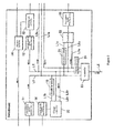
- Figure 1 is a schematic structural block diagram of the energy display system disclosed in the present invention
- Figure 2 is a schematic structural diagram of the switchboard shown in the block diagram in Figure 1 .
- the energy display system comprises: system side power source 1, designed to supply external grid power; a solar electric power generation device 2, installed at the house side and used as an in-housed electric power generation device that utilizes natural energy to generate electric power; a thermal storage device (household electric load) 3, an electric power operated vehicle (traveling object) 4, such as a plug-in hybrid vehicle (PHV) or electric vehicle (EV), etc.; electric appliances (household electric loads) 5 ⁇ arranged at the house side; a electric storage device 6; and a display device 7, etc.
- the system side Power source 1 supplies power from an electric utility company and it is connected to a first electric power detection device 11 arranged on a switchboard 10.
- the power consumption of external grid power can be detected by the first electric power detection device 11
- the first electric power detection device 11 is connected to the display device 7, and the power consumption of grid power detected by the first electric power detection device 11 is displayed on the screen of the display device 7.
- the solar electric power generation device 2 is an in-house electric power generation device that converts solar energy into DC electric power directly, and it is connected to the second electric power detection device 12 arranged on the switchboard 10.
- the power consumption of generated electric power of the solar electric power generation device 2 can be detected by the second electric power detection device 12.
- the second electric power detection device 12 is connected to the display device 7, and the power consumption of generated electric power detected by the second electric power detection device 12 is displayed on the display screen of the display device 7.
- the electricity sale controller 13 has a function of selling the electric power generated by the solar electric power generation device 2 to the electric utility company via the system side Power source 1.
- the electricity sale controller 13 is connected to the display device 7, and can be operated on the display device 7.
- the electricity sale controller 13 can be operated on the display device 7 to sell the surplus electric power generated by the solar electric power generation device 2.
- the electricity sale controller 13 has a built-in electricity meter, which can detect the sold electric quantity; the sold electric quantity detected by the electricity meter is displayed on the display screen of the display device 7, and at the same time, the after-mentioned electricity fee calculation device 32 arranged on the display device 7 calculates the electricity fee, and the electricity fee is displayed on the display device 7.
- the generated electric power is converted into AC electric power by an electric inverter 14 before it is sold.
- the thermal storage device (household electric load) 3 (e.g., an electric heater that utilizes thermal pump technique to boil up water with the thermal energy of air) is connected to the third electric power detection device 15 arranged on the switchboard 10.
- the third electric power detection device 15 is connected to the display device 7, and the power consumption of the thermal storage device 3 detected by the third electric power detection device 15 is displayed on the display screen of the display device 7.
- the thermal storage device 3 drives an electric motor for the thermal pump with DC electric power.
- the traveling object 4 is electric power operated vehicle, such as a power hybrid vehicle (PHV) or electric vehicle (EV), etc., which has a rechargeable storage battery (battery) that is not shown.
- the traveling object 4 is not limited to four-wheel vehicles, which is to say, it can also be a two-wheel motorcycle or motor scooter.
- the storage battery of the traveling object 4 is connected with a charging cable 4a in a removable manner, and the charging cable 4a is connected to the fourth electric power detection device 16.
- the fourth electric power detection device 16 is connected to the display device 7, and the power consumption resulting from charging of the traveling object 4 detected by the fourth electric power detection device 16 is displayed on the display screen of the display device 7.
- the electric appliances (household electric loads) 5 ⁇ are household electric appliance arranged in the home, such as refrigerator, washing machine, air conditioner, TV set, and electric lamp, etc., and they are connected to the third electric power detection device 17 respectively.
- the third electric power detection device 17 is connected to the display device 7, and the power consumption of the electric appliances 5 detected by the third electric power detection device 17 is displayed on the display screen of the display device 7.
- the third electric power detection device 17 is not arranged on the switchboard 10 directly; but it is connected to the electric appliances 5 and then connected to the switchboard 10; however, it can arranged on the switchboard 10 alternatively.
- the electrical storage device 6 is designed to store the surplus electric power generated by the solar electric power generation device 2 and the grid power that is cheaper during nocturnal time, and can discharge as required.
- the electrical storage device 6 comprises a storage battery 6a composed of Li-ion cells, etc., an electric inverter 6b, and a charge/discharge controller 6c.
- the electric inverter 6b is an inverter that converts AC grid power to DC electric power, and is controlled by the charge/discharge controller 6c.
- the charge/discharge controller 6c controls the charge/discharge of the storage battery 6a, and thereby stores the DC electric power converted by the electric inverter 6b from the grid power in the storage battery 6a or store the DC electric power generated by the solar electric power generation device 2 in the storage battery 6a, and discharge the electric power stored in the storage battery 6a as required.
- the discharged electric power is supplied to the traveling object 4, thermal storage device 3, and electric appliances 5, etc.
- the charge/discharge controller 6c is connected to the display device 7, and can be operated on the screen of the display device 7.
- the charge/discharge controller 6c can be instructed to charge/discharge by operating and setting on the screen of the display device 7.
- the operation mode, start time of charge/discharge, end time of charge/discharge, and electric power priority during charging, etc. can be set on the screen of the display device 7.
- the electric power priority during charging refers to the precedence in which the grid power (system side Power source 1) or generated electric power (solar electric power generation device 2) is used as the electric power for charging first.
- wiring L1 for supply of grid power from the system side Power source 1 wiring L2 for supply of generated power from the solar electric power generation device 2, and wiring L3 for supply of stored power from the electrical storage device 6 are arranged in the switchboard 10.
- the wiring L1 is for supply of AC power; wiring L1a is branched from wiring L1 and is connected to the electrical storage device 6, to supply AC power to the electrical storage device 6.
- AC power is converted into DC power by the electric inverter 6b and stored in storage battery 6a.
- the storage battery 6a and electric inverter 6b are controlled appropriately by the charge/discharge controller 6c.
- the electrical storage device 6 has a built-in electricity meter 6d, and the stored electric quantity detected by the electricity meter 6d is displayed on the display screen of the display device 7.
- the electricity meter 6d can detect the electric quantity discharged from the storage battery 6, and the discharged electric quantity is displayed on the display screen of the display device 7.
- wiring L1b is branched from the wiring L1, and is connected to the charge controller 20 via an electric inverter 18.
- the electric inverter 18 is an inverter that converts AC electric power to DC electric power.
- the charge controller 20 is a controller that controls the DC power supplied for charging the storage battery of the traveling object 4, and it is connected to the display device 7 and can be operated on the display device 7. For example, the charge controller 20 can be instructed to charge by operating and setting on the screen of the display device 7. When the charge controller 20 is instructed to charge, the operation mode, start time of charge, end time of charge, and priority of utilized electric power, etc., can be set on the screen of the display device 7.
- the priority of utilized electric power refers to the precedence in which the grid power (system side Power source 1), generated electric power (solar electric power generation device 2), or stored electric power (electrical storage device 6) is used as the utilized electric power first.
- automatic mode and manual mode are available for the operation mode.
- the charge controller 20 operates automatically, and charge the storage battery on the traveling object 4 according to the preset start time of charge, end time of charge, and priority of utilized electric power, etc..
- the grid power system side Power source 1
- generated electric power solar electric power generation device 2
- stored electric power electrical storage device 6
- wiring L1c is branched from the wiring L1, and is connected to a controller 22 via an electric inverter 21.
- the electric inverter 21 is an inverter that converts AC electric power to DC electric power.
- the controller 22 is a controller that controls the DC power supply to the thermal storage device 3, and it is connected to the display device 7 and can be operated on the display device 7. For example, the controller 22 can be instructed to supply power by operating and setting on the screen of the display device 7. When the controller 22 is instructed to supply power, the operation mode, start time of power supply, end time of power supply, and priority of utilized electric power, etc., can be set on the screen of the display device 7.
- the priority of utilized electric power refers to the precedence in which the grid power (system side Power source 1), generated electric power (solar electric power generation device 2), or stored electric power (electrical storage device 6) is used as the utilized electric power first.
- automatic mode and manual mode are available for the operation mode.
- the controller 22 operates automatically, and supplies power to the thermal storage device 3 according to the preset start time of charge, end time of charge, and priority of utilized electric power, etc..
- the grid power system side Power source 1
- generated electric power solar electric power generation device 2
- stored electric power electrical storage device 6
- the wiring L2 is for supply of DC electric power; wiring L2a is branched from the wiring L2, and is connected to the electrical storage device 6 to supply DC electric power to the electrical storage device 6.
- the DC electric power is stored in the storage battery 6a; during electric power storage, the storage battery 6a and electric inverter 6b are controlled appropriately by the charge/discharge controller 6c.
- wiring L2b is branched from the wiring L2, and is connected to the charge controller 20.
- wiring L2c is branched from the wiring L2, and is connected to the controller 22.
- the wiring L3 is the wiring for supply of DC power; wiring L3b is branched from the wiring L3, and is connected to the charge controller 20.
- wiring L3c is branched from the wiring L3, and is connected to the controller 22.
- the wiring L1 is directly connected to a controller 23 and the wiring L2 and L2 are connected to the controller 23 via the electric inverter 24 respectively.
- the electric inverter 24 is an inverter that converts AC electric power to DC electric power.
- the controller 23 is connected to the wiring L4.
- Wiring L4 is the wiring for supply of AC power from the switchboard 10 to the electric appliances (household electric appliances) 5; wirings L4a ⁇ are branched from the wiring L4 and are connected to the electric appliances 5 via the third electric power detection device 17.
- the controller 23 is a controller that controls AC power supply through the wiring L4, the AC power is AC power supplied by the wiring L1, AC power converted by the electric inverter 24 from the DC power supplied by the wiring L2, and AC power converted by the electric inverter 24 from the DC power supplied by the wiring L3; the controller 23 is connected to the display device 7, and can be operated on the display device 7.
- the controller 23 can be instructed to supply power by operating and setting on the screen of the display device 7.
- the controller 22 is instructed to supply power, the operation mode, start time of power supply, end time of power supply, and priority of utilized electric power, etc., can be set on the screen of the display device 7.
- the priority of utilized electric power refers to the precedence in which the grid power (system side Power source 1), generated electric power (solar electric power generation device 2), or stored electric power (electrical storage device 6) is used as the utilized electric power first.
- automatic mode and manual mode are available for the operation mode.
- the controller 23 operates automatically, and supplies power through the wiring L4 according to the preset start time of charge, end time of charge, and priority of utilized electric power, etc..
- the grid power system side Power source 1
- generated electric power solar electric power generation device 2
- stored electric power electrical storage device 6
- the third electric power detection device 17 can detect the power consumption of the electric appliances (household electric loads) 5 according to the grid power, generated power, and stored power.
- the power consumption of the electric appliances (household electric loads) 5 can be detected by the third electric power detection device 17 according to the grid power, generated power, and stored power, by controlling the electric power supplied through the wiring L4 with the controller 23 appropriately.
- the third electric power detection device 15 can also detect the power consumption of the thermal storage device (household electric load) 3 according to the grid power, generated power, and stored power.
- the power consumption of the thermal storage device (household electric load) 3 can be detected by the third electric power detection device 15 according to the grid power, generated power, and stored power, by controlling the electric power supplied to the thermal storage device 3 with the controller 22 appropriately.
- the fourth electric power detection device 16 can detect the power consumption resulting from charging of the traveling object 4 according to the grid power, generated power, and stored power.
- the power consumption resulting from charging of the traveling object 4 can be detected by the fourth electric power detection device 16 according to the grid power, generated power, and stored power, by controlling the electric power supplied to the traveling object 4 with the charge controller 20 appropriately.
- the display device 7 has a power consumption display part 30.
- the power consumption display part 30 displays the power consumption of the household electric loads (thermal storage device 3, electric appliances 5) according to the grid power, generated power, and stored power, on the basis of the power consumption detected by the third electric power detection devices 15 and 17 respectively, and displays the power consumption resulting from charging of the traveling object 4 according to the grid power, generated power, and stored power, on the basis of power consumption detected by the fourth electric power detection device 16 respectively.
- the power consumption display part 30 displays the total power consumption of grid power according to the power consumption detected by the first electric power detection device, displays the total power consumption of generated power according to the power consumption detected by the second electric power detection device, and displays the total power consumption of stored power according to the power consumption detected by the built-in electricity meter 6d in the electrical storage device 6.
- the power consumption is displayed on the power consumption display part 30 on daily, monthly, and annual basis.
- the power consumption is displayed in figures and diagrams.
- the user can set a target value of power consumption, and display the ratios of actual power consumption to the target value on daily, monthly, and annual basis.
- the target value is the maximum value of power consumption, and is set to prevent exceeding that maximum value.
- the electricity meter 6d in the electrical storage device 6 detects the level of utilization (charging) of grid power and generated power when the electrical storage device 6 is charged with grid power and generated power. In addition, the detected power consumption is displayed on the power consumption display part 30.
- the electricity meter 6d in the electrical storage device 6 detects the level of utilization (charging) of grid power and generated power when the electrical storage device 6 is charged with grid power and generated power. In addition, the detected power consumption is displayed on the power consumption display part 30.
- the display device 7 has a carbon dioxide emission calculation device 31.
- the carbon dioxide emission calculation device 31 calculates the emission amount of carbon dioxide from generation of electric quantity equivalent to the power consumption of grid power detected by the first electric power detection device 11, and the calculated emission amount of carbon dioxide is displayed on a display part 31a.
- the carbon dioxide emission calculation device 31 calculates the emission amount of carbon dioxide from generation of electric quantity equivalent to the electric quantity of grid power consumed by the household electric loads 3 and 5 detected by the third electric power detection device 15 and 17, and the calculated emission amount of carbon dioxide is displayed on a display part 31b.
- the carbon dioxide emission calculation device 31 calculates the emission amount of carbon dioxide from generation of electric quantity equivalent to power consumption of grid power resulting from charging of the traveling object 4 detected by the fourth electric power detection device 16, and the calculated emission amount of carbon dioxide is displayed on a display part 31c.
- the emission amount of carbon dioxide is displayed on daily, monthly, and annual basis on the power consumption display part 30.
- the emission amount of carbon dioxide is displayed in figures and diagrams.
- the user can set a target value of the emission amount of carbon dioxide, and the ratios of actual emission amount of carbon dioxide to target value are displayed on the display parts 31a, 31b, and 31c on daily, monthly, and annual basis.
- the target value is the maximum value of the emission amount of carbon dioxide, and is set to prevent exceeding that maximum value.
- the carbon dioxide emission calculation device 31 can calculate the accumulative total emission amount of carbon dioxide from generation of electric quantity equivalent to the total power consumption of grid power, the accumulative total emission amount of carbon dioxide from generation of electric quantity equivalent to the power consumption of grid power resulting from the household electric loads 3 and 5, and the accumulative total emission amount of carbon dioxide from generation of electric quantity equivalent to the power consumption of grid power resulting from charging of the traveling object 4, respectively, and the calculated accumulative total emission amounts of carbon dioxide are displayed on the display part 31a, 31b, and 31c, respectively.
- the carbon dioxide emission calculation device 31 performs calculation by subtracting the emission amount of carbon dioxide from generation of electric quantity equivalent to the power consumption of grid power resulting from charging of the traveling object 4 from the emission amount of carbon dioxide from a gasoline vehicle that has the same power as the traveling object 4.
- the calculated value is displayed on a display part, such as the display part 31c.
- the display device 7 has an electricity fee calculation device 32.
- the electricity fee calculation device 32 calculates the electricity fee equivalent to the total power consumption of grid power according to the power consumption of grid power detected by the first electric power detection device 11, and the calculated electricity fee is displayed on a display part 32a.
- the electricity fee calculation device 32 calculates the electricity fee equivalent to the electric quantity of grid power consumed by the household electric loads 3 and 5 detected by the third electric power detection device 15 and 17, and the calculated electricity fee is displayed on the display part 32b.
- the electricity fee calculation device 32 calculates the electricity fee equivalent to the power consumption of grid power resulting from charging of the traveling object 4 detected by the fourth electric power detection device 16, and the calculated electricity fee is displayed on a display part 32c.
- the electricity fee calculation device 32 calculates the electricity fee equivalent to the charged electric quantity detected by the built-in electricity meter in the electricity sale controller 13, and subtracts the electricity fee equivalent to the sold electric quantity from the electricity fee equivalent to the total power consumption of grid power, and the calculated electricity fee is displayed on the display part 32a, when the surplus generated power from the solar electric power generation device 2 is sold.
- the electricity fees are displayed on the corresponding display part 32a, 32b, and 32c on daily, monthly, and annual basis.
- the electricity fees are displayed in figures and diagrams.
- the user can set a target value of electricity fee, and the ratios of actual electricity fee to target value are displayed on the display part 32a, 32b, and 32c on daily, monthly, and annual basis.
- the target value is the maximum value of electricity fee, and is set to prevent exceeding that maximum value.
- the display device 7 has a suggestion display function for the ratio of actual value/target value of power consumption, ratio of actual value/target value of the emission amount of carbon dioxide, and ratio of actual value/target value of electricity fee.
- the suggestion display function will prompt the user for energy conservation by means of voice prompt or indicator flashing, etc., once the ratio of actual value to target value reaches or exceeds 90%.
- the display device 7 has a function for suggesting the priority setting for charging of the electrical storage device 6, charging of the storage battery (battery) of the traveling object 4, and operation of the thermal storage device 3, etc., and thereby the electric power that produces the least emission amount of carbon dioxide can be utilized.
- the suggestion is provided to the user by means of figures and diagrams on the display screen or voice prompt, etc..
- the user can set the priority in advance on a selection screen of the display device 7.
- the display device 7 has a travel distance calculation device 33.
- the travel distance calculation device 33 calculates the travel distance for which the traveling object 4 can move according to the power consumption resulting from charging of the traveling object 4, and the calculated travel distance is displayed on a display part 33a.
- the travel distance calculation device 33 calculates the travel distance of traveling object 4 equivalent to the power consumption of grid power resulting from charging of the traveling object 4 detected by the fourth electric power detection device 16, and the calculated travel distance is displayed on a display part 33b.
- the travel distance calculation device 33 calculates the travel distance equivalent to the power consumption of generated power resulting from charging of the traveling object 4 detected by the fourth electric power detection device 16, and the calculated travel distance is displayed on a display part 33c.
- the travel distance calculation device 33 calculates the travel distance equivalent to the power consumption of stored power resulting from charging of the traveling object 4 detected by the fourth electric power detection device 16, and the calculated travel distance is displayed on a display part 33d.
- the travel distance calculation device 33 checks whether any residual electricity remains in the storage battery (battery); if there is residual electricity in the storage battery (battery), the travel distance calculation device 33 detects the residual electric quantity, adds the travel distance equivalent to the residual electric quantity to the travel distance of traveling object 4 calculated on the basis of the electric quantity charged to the traveling object 4, and displays the result on the display part 33a.
- the travel distance calculation device 33 can calculate the accumulative total travel distance of the traveling object, and display the calculated accumulative total travel distance on the display part 33a.
- the travel distance calculation device 33 checks whether any residual electricity remains in the storage battery (battery); if there is residual electricity in the storage battery (battery), the travel distance calculation device 33 detects the residual electric quantity, and calculates the accumulative total travel distance of the traveling object 4 by calculating the accumulative total electric quantity charged to the storage battery (battery) of the traveling object 4 in the previous charge cycles and subtracting the residual electric quantity, and the calculated accumulative total travel distance is displayed on the display part 33a.
- the travel distance calculation device 33 calculates the accumulative total travel distance of the traveling object by calculating the accumulative total electric quantity charged to the storage battery (battery) of the traveling object 4 in the previous charge cycles, and the calculated accumulative total travel distance is displayed on the display part 33a.
- the power consumption of external grid power is detected by the first electric power detection device 11 and displayed on the display device 7
- the power consumption of generated power from the solar electric power generation device 2 is detected by the second electric power detection device 12 and displayed on the display device 7
- the power consumption of stored power in the electrical storage device 6 is detected by the electricity meter 6d and displayed on the display device 7
- the power consumption of the household electric loads 3 and 5 are detected by the third electric power detection device 15 and 17 on the basis of grid power, generated power, and stored power and displayed on the display device 7,
- the power consumption resulting from charging of the traveling object is detected by the fourth electric power detection device 16 on the basis of grid power, generated power, and stored power and displayed on the display device 7; hence, the power consumption of the household electric loads 3 and 5 and the power consumption resulting from charging of the traveling object 4 can be displayed on the basis of grid power, generated power, and stored power respectively.
- the display device 7 has a carbon dioxide emission calculation device 31, which calculates the emission amount of carbon dioxide from generation of electric quantity equivalent to the power consumption of grid power detected by the first electric power detection device 11; thereby, the calculated emission amount of carbon dioxide can be displayed on the display device 7.
- the carbon dioxide emission calculation device 31 can calculate the emission amount of carbon dioxide from generation of electric quantity equivalent to the power consumption of grid power resulting from the household electric load 3 and 5 and the emission amount of carbon dioxide from generation of electric quantity equivalent to the power consumption of grid power resulting from charging of the traveling object 4 respectively; therefore, the two types of emission amount of carbon dioxide can be displayed on the display device 7.
- the carbon dioxide emission calculation device 31 can calculate the accumulative total emission amount of carbon dioxide from generation of electric quantity equivalent to the power consumption of grid power resulting from charging of the traveling object 4; therefore, the calculated accumulative total emission amount of carbon dioxide can be displayed on the display device 7.
- the energy display system has an electricity fee calculation device 32 that calculates the electricity fee caused by charging of the traveling object 4 according to the power consumption of grid power resulting from charging of the traveling object 4, a travel distance calculation device 33 that calculates the travel distance for which the traveling object 4 can move according to the power consumption resulting from charging of the traveling object 4; therefore, the calculated electricity fee caused by charging of the traveling object 4 and the travel distance of the traveling object 4 can be displayed on the display device 7.
- the electricity fee calculation device 32 can calculate the accumulative total electricity fee caused by charging of the traveling object 4 and the accumulative total travel distance of the traveling object 4; therefore, the calculated accumulative total electricity fee and accumulative total travel distance can be displayed on the display device 7.
- the system has a charge controller 20 that can select any one of the grid power, generated power, and stored power as the electric power for charging of the traveling object 4; the charge controller 20 is connected to the display device 7, and can be operated via the display device 7; therefore, any one of the grid power, generated power, and stored power can be selected as the electric power for charging of the traveling object 4.
- the operation mode, start time of charge, end time of charge, and priority of utilized power, etc. can be set for the charge controller 20 which can be operated and set on the operating screen of the display device 7; therefore, the storage battery of the traveling object 4 can be charged easily and effectively.
- the controller 22 connected to the thermal storage device 3 can be operated and set on the operating screen of the display device 7, which is to say, the operation mode, start time of power supply, end time of power supply, and priority of utilized power, etc., can be set on the operating screen of the display device 7; therefore, the power supply to the thermal storage device 3 can be controlled easily and effectively.
- the balance, variation, and accumulative total (Accumulation) of power consumption, balance, variation, and accumulative total (Accumulation) of electricity fee, and balance, variation, and accumulative total (Accumulation) of emission amount of carbon dioxide can be stored as data on daily, monthly, and annual basis. Furthermore, the user can confirm the stored data as required.
- the display device 7 has a suggestion display function for the ratio of actual value/target value of power consumption, ratio of actual value/target value of the emission amount of carbon dioxide, and ratio of actual value/target value of electricity fee; therefore, it can prompt the user for energy conservation.
- this embodiment is described in an example of solar electric power generation device 2; however, a wind electric power generation device can be used as an alternate to the solar electric power generation device 2 for the household electric power generation device.
- the electric quantity consumed by the household electric loads is detected by the third electric power detection device on the basis of grid power and generated power and displayed on the display device
- the power consumption resulting from charging of the traveling object is detected by the fourth electric power detection device on the basis of grid power and generated power and displayed on the display device; hence, the electric quantity consumed by the household electric loads and the power consumption resulting from charging of the traveling object can be displayed on the basis of grid power and generated power respectively.
Landscapes
- Engineering & Computer Science (AREA)
- Power Engineering (AREA)
- Physics & Mathematics (AREA)
- General Physics & Mathematics (AREA)
- Charge And Discharge Circuits For Batteries Or The Like (AREA)
- Supply And Distribution Of Alternating Current (AREA)
- Remote Monitoring And Control Of Power-Distribution Networks (AREA)
Abstract
Description
- The present invention relates to an energy display system that can display the power consumption of household electric loads and the power consumption due to charging of traveling objects on the basis of the grid power and generated power respectively.
- Usually, household electric loads used in the home, such as refrigerators, washing machines, air conditioners, or other household electric appliances, etc., operate with AC electric power supply (grid power) from an electric utility company. Since the electric utility company claims for the electricity fee on the basis of the consumption (usage) of electric power, the consumption (usage) of electric power and corresponding electricity fee can be ascertained from the bill.
- In recent years, the problem of global warming became extremely urgent, and the emission of carbon dioxide (CO2) in the refining process of electric power that is used as the energy source became a major cause for global warming. However, at present, the awareness of emission of carbon dioxide in the refining process of electric power consumed for household purpose is still very low among ordinary demanders.
- Hence, as an example of display system that displays the data including the power consumption by household electric loads such as electric appliances, etc. and the emission amount of carbon dioxide from generation of the power consumption, etc., the apparatus disclosed in
patent document 1 is known to ordinary demanders. - The display system comprises: a plurality of electric appliance groups, each of which operates with commercial AC power supply and has electric power consumption detection devices respectively; a calculation device, which calculates the electricity fee or the emission amount of carbon dioxide produced in the production process of the power consumption in real time according to the power consumption of the electric appliances which is output from the electric appliance groups or preset reference data; and, a display device, which displays the calculation result of the calculation device.
- With such a display system, the user can ascertain the data of power consumption of each electric appliance and the data of emission amount of carbon dioxide produced in the production process of the power consumption on the display device. As a result, the system is helpful for enhancing the user's awareness of energy conservation and reducing unnecessary or excessive electric power consumption, and thereby attains the object of energy conservation.
- Patent documents:
- Patent document 1: Patent Publication No.
JP2002-40065 - In recent years, in-house electric power generation devices (e.g., solar electric power generation devices, etc.) were utilized to supply power to household electric loads in homes. However, since traditional display systems can't display the electric quantity consumed by power generation in the electric power consumption of household electric loads, it is difficult to ascertain the exact level of reduction of electric power by electric power generation.
- In addition, in recent years, electric power operated vehicles such as plug-in hybrid vehicles (PHVs) and electric vehicles (EVs), etc. were developed, and some products have been introduced into the market. For such electric power operated vehicles (traveling objects), it is required to know the power consumption resulting from charging of the traveling objects on the basis of grid power and generated power when they are charged in homes.
- In view of above problems, the object of the present invention is to provide an energy display system, which can display the power consumption of household electric loads and power consumption resulting from charging of traveling objects on the basis of the grid power and generated power respectively.
- To solve above problems, as shown in
Figure 1∼3 , the invention described inclaim 1 comprises: a first electricpower detection device 11, which can detect the power consumption of external grid power;
a second electricpower detection device 12, which can detect the power consumption of electric power generated by an in-house power generation device (solar electric power generation devices) 2 that is installed at the side of house and utilizes natural energy to generate electric power;
third electricpower detection devices
a fourth electricpower detection device 16, which can detect the power consumption resulting from charging of a traveling object 4 on the basis of the grid power and generated power; and adisplay device 7, which is connected with the first through fourth electric power detection devices, and can display the power consumption detected by the first through fourth electric power detection devices. - The invention described in
claim 1, characterized in that: the power consumption of external grid power is detected by the first electricpower detection device 11 and displayed on thedisplay device 7; the power consumption of electric power generated by the in-house power generation device (solar electric power generation device) 2 is detected by the second electricpower detection device 12 and displayed on thedisplay device 7; the power consumption of household electric loads is detected by the third electricpower detection devices display device 7; the power consumption resulting from charging of the traveling object 4 is detected by the fourth electricpower detection device 16 on the basis of the grid power and generated power and displayed on thedisplay device 7; thus, the power consumption of householdelectric loads 3 and 5 and the power consumption resulting from charging of the traveling object 4 can be displayed on the basis of the grid power and generated power respectively. - The invention described in
claim 2, characterized in that: in the energy display system described inclaim 1, thedisplay device 7 comprises a carbon dioxideemission calculation device 31, which calculates the emission amount of carbon dioxide from generation of electric quantity equivalent to the power consumption of grid power detected by the first electricpower detection device 11, and can display the calculated emission amount of carbon dioxide. - In the invention described in
claim 2, the carbon dioxideemission calculation device 31 calculates the emission amount of carbon dioxide from generation of electric quantity equivalent to the power consumption of grid power detected by the first electricpower detection device 11. Thus, the calculated emission amount of carbon dioxide can be displayed on thedisplay device 7. - The invention described in claim 3, characterized in that: in the energy display system described in
claim 2, the carbon dioxideemission calculation device 31 can calculate the emission amount of carbon dioxide from generation of electric quantity equivalent to the power consumption of grid power resulting from the householdelectric loads 3 and 5 and the emission amount of carbon dioxide from generation of electric quantity equivalent to the power consumption of grid power resulting from charging of the traveling object 4, respectively; - The
display device 7 can display the two types of calculated emission amount of carbon dioxide. - In the invention described in claim 3, the carbon dioxide
emission calculation device 31 calculates the emission amount of carbon dioxide from generation of electric quantity equivalent to the power consumption of grid power resulting from the householdelectric loads 3 and 5 and the emission amount of carbon dioxide from generation of electric quantity equivalent to the power consumption of grid power resulting from charging of the traveling object 4, respectively. Thus, the two types of calculated emission amount of carbon dioxide can be displayed on thedisplay device 7. - The invention described in claim 4, characterized in that: in the energy display system described in claim 3, the carbon dioxide
emission calculation device 31 can calculate the accumulative total emission amount of carbon dioxide from generation of electric quantity equivalent to the power consumption of grid power resulting from charging of the traveling object 4; - The
display device 7 can display the calculated accumulative total emission amount of carbon dioxide. - In the invention described in claim 4, the carbon dioxide
emission calculation device 31 calculates the accumulative total emission amount of carbon dioxide from generation of the electric quantity equivalent to the power consumption of grid power resulting from charging of the traveling object 4. Thus, the calculated accumulative total emission amount of carbon dioxide can be displayed on thedisplay device 7. - The invention described in
claim 5, characterized in that: the energy display system described in any one of claims 1-4 comprises an electricityfee calculation device 32, which calculates the electricity fee caused by charging of the traveling object 4 on the basis of the power consumption of grid power resulting from charging of the traveling object 4; and
a traveldistance calculation device 33, which calculates the travel distance for which the traveling object 4 can move, on the basis of the power consumption resulting from charging of the traveling object 4;
thedisplay device 7 can display the calculated electricity fee and travel distance. - In the invention described in
claim 5, the electricityfee calculation device 32 calculates the electricity fee caused by charging of the traveling object 4 on the basis of the power consumption of grid power resulting from charging of the traveling object 4; in addition, the traveldistance calculation device 33 calculates the travel distance for which the traveling object 4 can move on the basis of the power consumption resulting from charging of the traveling object 4. Thus, the electricity fee caused by charging of the traveling object 4 and the travel distance for which thetraveling object 14 can move can be displayed on thedisplay device 7. - The invention described in
claim 6, characterized in that: in the energy display system described inclaim 5, - The electricity
fee calculation device 32 can calculate the accumulative total electricity fee caused by charging of the traveling object 4; - The travel
distance calculation device 33 can calculate the accumulative total travel distance in which the traveling object 4 is used normally; - The
display device 7 can display the calculated accumulative total electricity fee and accumulative total travel distance. - In the invention described in
claim 6, the electricityfee calculation device 32 calculates the accumulative total electricity fee caused by charging of the traveling object 4, and the traveldistance calculation device 33 calculates the accumulative total travel distance of the traveling object 4. Thus, the calculated accumulative total electricity fee and accumulative total travel distance can be displayed on thedisplay device 7. - The invention described in
claim 7, characterized in that: in the energy display system described in any one of the claims 1-6,
the system comprises: acharge controller 20, which can select the grid power or the electric power generated by the in-house electric power generation device (solar electric power generation device) 2 as the electric power for charging of the traveling object 4;
thecharge controller 20 is connected to thedisplay device 7 and can be operated via thedisplay device 7. - In the invention described in
claim 7, thecharge controller 20 is operated via thedisplay device 7 to select the grid power or the generated power as the electric power for charging of the traveling object 4. - In the present invention, the power consumption of the household electric loads is detected by the third electric power detection device on the basis of grid power and generated power and displayed on the display device, the power consumption resulting from charging of the traveling object is detected by the fourth electric power detection device on the basis of grid power and generated power and displayed on the display device, so that the power consumption of the household electric loads and the power consumption resulting from charging of the traveling object can be displayed on the basis of grid power and generated power respectively.
-
-
Figure 1 is a schematic structural block diagram of an example of the energy display system disclosed in the present invention. -
Figure 2 is a schematic structural diagram of the switchboard. -
Figure 3 is a schematic structural block diagram of the display device. -
- 1. System side Power source
- 2. Solar electric power generation device (in-house electric power generation device)
- 3. Thermal storage device (household electric load)
- 4. Traveling object
- 5. Electric appliance (household electric load)
- 6. Electrical storage device
- 7. Display device
- 11. First electric power detection device
- 12. Second electric power detection device
- 15, 17. Third electric power detection device
- 16. Fourth electric power detection device
- 31. Carbon dioxide emission calculation device
- 32. Electricity fee calculation device
- 33. Travel distance calculation device
- Hereunder the energy display system disclosed in the present invention will be described in embodiments, with reference to the accompanying drawings.
-
Figure 1 is a schematic structural block diagram of the energy display system disclosed in the present invention;Figure 2 is a schematic structural diagram of the switchboard shown in the block diagram inFigure 1 . - The energy display system according to the embodiment comprises: system
side power source 1, designed to supply external grid power; a solar electricpower generation device 2, installed at the house side and used as an in-housed electric power generation device that utilizes natural energy to generate electric power; a thermal storage device (household electric load) 3, an electric power operated vehicle (traveling object) 4, such as a plug-in hybrid vehicle (PHV) or electric vehicle (EV), etc.; electric appliances (household electric loads) 5 ···arranged at the house side; aelectric storage device 6; and adisplay device 7, etc.. - The system
side Power source 1 supplies power from an electric utility company and it is connected to a first electricpower detection device 11 arranged on aswitchboard 10. The power consumption of external grid power can be detected by the first electricpower detection device 11 The first electricpower detection device 11 is connected to thedisplay device 7, and the power consumption of grid power detected by the first electricpower detection device 11 is displayed on the screen of thedisplay device 7. - The solar electric
power generation device 2 is an in-house electric power generation device that converts solar energy into DC electric power directly, and it is connected to the second electricpower detection device 12 arranged on theswitchboard 10. The power consumption of generated electric power of the solar electricpower generation device 2 can be detected by the second electricpower detection device 12. The second electricpower detection device 12 is connected to thedisplay device 7, and the power consumption of generated electric power detected by the second electricpower detection device 12 is displayed on the display screen of thedisplay device 7. - In addition, there is an
electricity sale controller 13 between the solar electricpower generation device 2 and the second electricpower detection device 12, and the solar electricpower generation device 2 is connected to the second electricpower detection device 12 via theelectricity sale controller 13. - The
electricity sale controller 13 has a function of selling the electric power generated by the solar electricpower generation device 2 to the electric utility company via the systemside Power source 1. Theelectricity sale controller 13 is connected to thedisplay device 7, and can be operated on thedisplay device 7. Theelectricity sale controller 13 can be operated on thedisplay device 7 to sell the surplus electric power generated by the solar electricpower generation device 2. Theelectricity sale controller 13 has a built-in electricity meter, which can detect the sold electric quantity; the sold electric quantity detected by the electricity meter is displayed on the display screen of thedisplay device 7, and at the same time, the after-mentioned electricityfee calculation device 32 arranged on thedisplay device 7 calculates the electricity fee, and the electricity fee is displayed on thedisplay device 7. - In addition, owing to the fact that the electric power generated by the solar electric
power generation device 2 is DC electric power, the generated electric power is converted into AC electric power by anelectric inverter 14 before it is sold. - The thermal storage device (household electric load) 3 (e.g., an electric heater that utilizes thermal pump technique to boil up water with the thermal energy of air) is connected to the third electric
power detection device 15 arranged on theswitchboard 10. The third electricpower detection device 15 is connected to thedisplay device 7, and the power consumption of the thermal storage device 3 detected by the third electricpower detection device 15 is displayed on the display screen of thedisplay device 7. - In addition, the thermal storage device 3 drives an electric motor for the thermal pump with DC electric power.
- As described above, the traveling object 4 is electric power operated vehicle, such as a power hybrid vehicle (PHV) or electric vehicle (EV), etc., which has a rechargeable storage battery (battery) that is not shown. In addition, the traveling object 4 is not limited to four-wheel vehicles, which is to say, it can also be a two-wheel motorcycle or motor scooter.
- The storage battery of the traveling object 4 is connected with a charging
cable 4a in a removable manner, and the chargingcable 4a is connected to the fourth electricpower detection device 16. The fourth electricpower detection device 16 is connected to thedisplay device 7, and the power consumption resulting from charging of the traveling object 4 detected by the fourth electricpower detection device 16 is displayed on the display screen of thedisplay device 7. - The electric appliances (household electric loads) 5 ··· are household electric appliance arranged in the home, such as refrigerator, washing machine, air conditioner, TV set, and electric lamp, etc., and they are connected to the third electric
power detection device 17 respectively. The third electricpower detection device 17 is connected to thedisplay device 7, and the power consumption of theelectric appliances 5 detected by the third electricpower detection device 17 is displayed on the display screen of thedisplay device 7. - Moreover, in this embodiment, the third electric
power detection device 17 is not arranged on theswitchboard 10 directly; but it is connected to theelectric appliances 5 and then connected to theswitchboard 10; however, it can arranged on theswitchboard 10 alternatively. - The
electrical storage device 6 is designed to store the surplus electric power generated by the solar electricpower generation device 2 and the grid power that is cheaper during nocturnal time, and can discharge as required. Theelectrical storage device 6 comprises astorage battery 6a composed of Li-ion cells, etc., anelectric inverter 6b, and a charge/discharge controller 6c. Theelectric inverter 6b is an inverter that converts AC grid power to DC electric power, and is controlled by the charge/discharge controller 6c. Moreover, the charge/discharge controller 6c controls the charge/discharge of thestorage battery 6a, and thereby stores the DC electric power converted by theelectric inverter 6b from the grid power in thestorage battery 6a or store the DC electric power generated by the solar electricpower generation device 2 in thestorage battery 6a, and discharge the electric power stored in thestorage battery 6a as required. In addition, the discharged electric power is supplied to the traveling object 4, thermal storage device 3, andelectric appliances 5, etc. The charge/discharge controller 6c is connected to thedisplay device 7, and can be operated on the screen of thedisplay device 7. For example, the charge/discharge controller 6c can be instructed to charge/discharge by operating and setting on the screen of thedisplay device 7. When the charge/discharge controller 6c is instructed to charge/discharge, the operation mode, start time of charge/discharge, end time of charge/discharge, and electric power priority during charging, etc., can be set on the screen of thedisplay device 7. - In addition, the electric power priority during charging refers to the precedence in which the grid power (system side Power source 1) or generated electric power (solar electric power generation device 2) is used as the electric power for charging first.
- As shown in
Figure 1 andFigure 2 , wiring L1 for supply of grid power from the systemside Power source 1, wiring L2 for supply of generated power from the solar electricpower generation device 2, and wiring L3 for supply of stored power from theelectrical storage device 6 are arranged in theswitchboard 10. - The wiring L1 is for supply of AC power; wiring L1a is branched from wiring L1 and is connected to the
electrical storage device 6, to supply AC power to theelectrical storage device 6. In theelectrical storage device 6, AC power is converted into DC power by theelectric inverter 6b and stored instorage battery 6a. During power storage, thestorage battery 6a andelectric inverter 6b are controlled appropriately by the charge/discharge controller 6c. Moreover, theelectrical storage device 6 has a built-inelectricity meter 6d, and the stored electric quantity detected by theelectricity meter 6d is displayed on the display screen of thedisplay device 7. In addition, theelectricity meter 6d can detect the electric quantity discharged from thestorage battery 6, and the discharged electric quantity is displayed on the display screen of thedisplay device 7. - In addition, wiring L1b is branched from the wiring L1, and is connected to the
charge controller 20 via anelectric inverter 18. Theelectric inverter 18 is an inverter that converts AC electric power to DC electric power. - The
charge controller 20 is a controller that controls the DC power supplied for charging the storage battery of the traveling object 4, and it is connected to thedisplay device 7 and can be operated on thedisplay device 7. For example, thecharge controller 20 can be instructed to charge by operating and setting on the screen of thedisplay device 7. When thecharge controller 20 is instructed to charge, the operation mode, start time of charge, end time of charge, and priority of utilized electric power, etc., can be set on the screen of thedisplay device 7. - In addition, the priority of utilized electric power refers to the precedence in which the grid power (system side Power source 1), generated electric power (solar electric power generation device 2), or stored electric power (electrical storage device 6) is used as the utilized electric power first.
- Moreover, automatic mode and manual mode are available for the operation mode. When automatic mode is selected, the
charge controller 20 operates automatically, and charge the storage battery on the traveling object 4 according to the preset start time of charge, end time of charge, and priority of utilized electric power, etc.. When manual mode is selected, the grid power (system side Power source 1), generated electric power (solar electric power generation device 2), or stored electric power (electrical storage device 6) can be selected to charge the storage battery. - In addition, wiring L1c is branched from the wiring L1, and is connected to a
controller 22 via anelectric inverter 21. Theelectric inverter 21 is an inverter that converts AC electric power to DC electric power. - The
controller 22 is a controller that controls the DC power supply to the thermal storage device 3, and it is connected to thedisplay device 7 and can be operated on thedisplay device 7. For example, thecontroller 22 can be instructed to supply power by operating and setting on the screen of thedisplay device 7. When thecontroller 22 is instructed to supply power, the operation mode, start time of power supply, end time of power supply, and priority of utilized electric power, etc., can be set on the screen of thedisplay device 7. - In addition, the priority of utilized electric power refers to the precedence in which the grid power (system side Power source 1), generated electric power (solar electric power generation device 2), or stored electric power (electrical storage device 6) is used as the utilized electric power first.
- Moreover, automatic mode and manual mode are available for the operation mode. When automatic mode is selected, the
controller 22 operates automatically, and supplies power to the thermal storage device 3 according to the preset start time of charge, end time of charge, and priority of utilized electric power, etc.. When manual mode is selected, the grid power (system side Power source 1), generated electric power (solar electric power generation device 2), or stored electric power (electrical storage device 6) can be selected to supply power to the thermal storage device 3. - The wiring L2 is for supply of DC electric power; wiring L2a is branched from the wiring L2, and is connected to the
electrical storage device 6 to supply DC electric power to theelectrical storage device 6. In theelectrical storage device 6, the DC electric power is stored in thestorage battery 6a; during electric power storage, thestorage battery 6a andelectric inverter 6b are controlled appropriately by the charge/discharge controller 6c. - In addition, wiring L2b is branched from the wiring L2, and is connected to the
charge controller 20. - In addition, wiring L2c is branched from the wiring L2, and is connected to the
controller 22. The wiring L3 is the wiring for supply of DC power; wiring L3b is branched from the wiring L3, and is connected to thecharge controller 20. - In addition, wiring L3c is branched from the wiring L3, and is connected to the
controller 22. The wiring L1 is directly connected to acontroller 23 and the wiring L2 and L2 are connected to thecontroller 23 via theelectric inverter 24 respectively. - The
electric inverter 24 is an inverter that converts AC electric power to DC electric power. Thecontroller 23 is connected to the wiring L4. Wiring L4 is the wiring for supply of AC power from theswitchboard 10 to the electric appliances (household electric appliances) 5; wirings L4a ··· are branched from the wiring L4 and are connected to theelectric appliances 5 via the third electricpower detection device 17. - In addition, the
controller 23 is a controller that controls AC power supply through the wiring L4, the AC power is AC power supplied by the wiring L1, AC power converted by theelectric inverter 24 from the DC power supplied by the wiring L2, and AC power converted by theelectric inverter 24 from the DC power supplied by the wiring L3; thecontroller 23 is connected to thedisplay device 7, and can be operated on thedisplay device 7. For example, thecontroller 23 can be instructed to supply power by operating and setting on the screen of thedisplay device 7. When thecontroller 22 is instructed to supply power, the operation mode, start time of power supply, end time of power supply, and priority of utilized electric power, etc., can be set on the screen of thedisplay device 7. - In addition, the priority of utilized electric power refers to the precedence in which the grid power (system side Power source 1), generated electric power (solar electric power generation device 2), or stored electric power (electrical storage device 6) is used as the utilized electric power first.
- Moreover, automatic mode and manual mode are available for the operation mode. When automatic mode is selected, the
controller 23 operates automatically, and supplies power through the wiring L4 according to the preset start time of charge, end time of charge, and priority of utilized electric power, etc.. When manual mode is selected, the grid power (system side Power source 1), generated electric power (solar electric power generation device 2), or stored electric power (electrical storage device 6) can be selected to supply power through the wiring L4. - The third electric
power detection device 17 can detect the power consumption of the electric appliances (household electric loads) 5 according to the grid power, generated power, and stored power. - That is to say, since the wiring L1 for supply of grid power, wiring L2 for supply of generated power, and wiring L3 for supply of stored power are connected to the
controller 23 respectively, the power consumption of the electric appliances (household electric loads) 5 can be detected by the third electricpower detection device 17 according to the grid power, generated power, and stored power, by controlling the electric power supplied through the wiring L4 with thecontroller 23 appropriately. - Similar to the third electric
power detection device 17, the third electricpower detection device 15 can also detect the power consumption of the thermal storage device (household electric load) 3 according to the grid power, generated power, and stored power. - That is to say, since the wiring L1 for supply of grid power, wiring L2 for supply of generated power, and wiring L3 for supply of stored power are connected to the
controller 22 respectively, the power consumption of the thermal storage device (household electric load) 3 can be detected by the third electricpower detection device 15 according to the grid power, generated power, and stored power, by controlling the electric power supplied to the thermal storage device 3 with thecontroller 22 appropriately. - The fourth electric
power detection device 16 can detect the power consumption resulting from charging of the traveling object 4 according to the grid power, generated power, and stored power. - That is to say, since the wiring L1 for supply of grid power, wiring L2 for supply of generated power, and wiring L3 for supply of stored power are connected to the
charge controller 20 respectively, the power consumption resulting from charging of the traveling object 4 can be detected by the fourth electricpower detection device 16 according to the grid power, generated power, and stored power, by controlling the electric power supplied to the traveling object 4 with thecharge controller 20 appropriately. - As shown in
Figure 3 , thedisplay device 7 has a powerconsumption display part 30. The powerconsumption display part 30 displays the power consumption of the household electric loads (thermal storage device 3, electric appliances 5) according to the grid power, generated power, and stored power, on the basis of the power consumption detected by the third electricpower detection devices power detection device 16 respectively. - In addition, the power
consumption display part 30 displays the total power consumption of grid power according to the power consumption detected by the first electric power detection device, displays the total power consumption of generated power according to the power consumption detected by the second electric power detection device, and displays the total power consumption of stored power according to the power consumption detected by the built-inelectricity meter 6d in theelectrical storage device 6. - Moreover, the power consumption is displayed on the power
consumption display part 30 on daily, monthly, and annual basis. The power consumption is displayed in figures and diagrams. In addition, in thedisplay device 7, the user can set a target value of power consumption, and display the ratios of actual power consumption to the target value on daily, monthly, and annual basis. In addition, the target value is the maximum value of power consumption, and is set to prevent exceeding that maximum value. - With the power consumption of household electric loads (thermal storage device 3 and electric appliances 5) taken into account, the
electricity meter 6d in theelectrical storage device 6 detects the level of utilization (charging) of grid power and generated power when theelectrical storage device 6 is charged with grid power and generated power. In addition, the detected power consumption is displayed on the powerconsumption display part 30. - Likewise, with the power consumption resulting from charging of the traveling object 4 taken into account, the
electricity meter 6d in theelectrical storage device 6 detects the level of utilization (charging) of grid power and generated power when theelectrical storage device 6 is charged with grid power and generated power. In addition, the detected power consumption is displayed on the powerconsumption display part 30. - The
display device 7 has a carbon dioxideemission calculation device 31. The carbon dioxideemission calculation device 31 calculates the emission amount of carbon dioxide from generation of electric quantity equivalent to the power consumption of grid power detected by the first electricpower detection device 11, and the calculated emission amount of carbon dioxide is displayed on adisplay part 31a. - In addition, the carbon dioxide
emission calculation device 31 calculates the emission amount of carbon dioxide from generation of electric quantity equivalent to the electric quantity of grid power consumed by the householdelectric loads 3 and 5 detected by the third electricpower detection device display part 31b. - In addition, the carbon dioxide
emission calculation device 31 calculates the emission amount of carbon dioxide from generation of electric quantity equivalent to power consumption of grid power resulting from charging of the traveling object 4 detected by the fourth electricpower detection device 16, and the calculated emission amount of carbon dioxide is displayed on adisplay part 31c. - Moreover, the emission amount of carbon dioxide is displayed on daily, monthly, and annual basis on the power
consumption display part 30. The emission amount of carbon dioxide is displayed in figures and diagrams. - Moreover, in the carbon dioxide
emission calculation device 31, the user can set a target value of the emission amount of carbon dioxide, and the ratios of actual emission amount of carbon dioxide to target value are displayed on thedisplay parts - The carbon dioxide
emission calculation device 31 can calculate the accumulative total emission amount of carbon dioxide from generation of electric quantity equivalent to the total power consumption of grid power, the accumulative total emission amount of carbon dioxide from generation of electric quantity equivalent to the power consumption of grid power resulting from the householdelectric loads 3 and 5, and the accumulative total emission amount of carbon dioxide from generation of electric quantity equivalent to the power consumption of grid power resulting from charging of the traveling object 4, respectively, and the calculated accumulative total emission amounts of carbon dioxide are displayed on thedisplay part - In addition, the carbon dioxide
emission calculation device 31 performs calculation by subtracting the emission amount of carbon dioxide from generation of electric quantity equivalent to the power consumption of grid power resulting from charging of the traveling object 4 from the emission amount of carbon dioxide from a gasoline vehicle that has the same power as the traveling object 4. In addition, the calculated value is displayed on a display part, such as thedisplay part 31c. - The
display device 7 has an electricityfee calculation device 32. The electricityfee calculation device 32 calculates the electricity fee equivalent to the total power consumption of grid power according to the power consumption of grid power detected by the first electricpower detection device 11, and the calculated electricity fee is displayed on adisplay part 32a. - In addition, the electricity
fee calculation device 32 calculates the electricity fee equivalent to the electric quantity of grid power consumed by the householdelectric loads 3 and 5 detected by the third electricpower detection device display part 32b. - In addition, the electricity
fee calculation device 32 calculates the electricity fee equivalent to the power consumption of grid power resulting from charging of the traveling object 4 detected by the fourth electricpower detection device 16, and the calculated electricity fee is displayed on adisplay part 32c. - In addition, the electricity
fee calculation device 32 calculates the electricity fee equivalent to the charged electric quantity detected by the built-in electricity meter in theelectricity sale controller 13, and subtracts the electricity fee equivalent to the sold electric quantity from the electricity fee equivalent to the total power consumption of grid power, and the calculated electricity fee is displayed on thedisplay part 32a, when the surplus generated power from the solar electricpower generation device 2 is sold. - Moreover, the electricity fees are displayed on the
corresponding display part - In addition, in the electricity
fee calculation device 32, the user can set a target value of electricity fee, and the ratios of actual electricity fee to target value are displayed on thedisplay part - Moreover, the
display device 7 has a suggestion display function for the ratio of actual value/target value of power consumption, ratio of actual value/target value of the emission amount of carbon dioxide, and ratio of actual value/target value of electricity fee. For example, the suggestion display function will prompt the user for energy conservation by means of voice prompt or indicator flashing, etc., once the ratio of actual value to target value reaches or exceeds 90%. - Moreover, the
display device 7 has a function for suggesting the priority setting for charging of theelectrical storage device 6, charging of the storage battery (battery) of the traveling object 4, and operation of the thermal storage device 3, etc., and thereby the electric power that produces the least emission amount of carbon dioxide can be utilized. The suggestion is provided to the user by means of figures and diagrams on the display screen or voice prompt, etc.. In addition, the user can set the priority in advance on a selection screen of thedisplay device 7. - The
display device 7 has a traveldistance calculation device 33. The traveldistance calculation device 33 calculates the travel distance for which the traveling object 4 can move according to the power consumption resulting from charging of the traveling object 4, and the calculated travel distance is displayed on adisplay part 33a. - In addition, the travel
distance calculation device 33 calculates the travel distance of traveling object 4 equivalent to the power consumption of grid power resulting from charging of the traveling object 4 detected by the fourth electricpower detection device 16, and the calculated travel distance is displayed on adisplay part 33b. - In addition, the travel
distance calculation device 33 calculates the travel distance equivalent to the power consumption of generated power resulting from charging of the traveling object 4 detected by the fourth electricpower detection device 16, and the calculated travel distance is displayed on adisplay part 33c. - In addition, the travel
distance calculation device 33 calculates the travel distance equivalent to the power consumption of stored power resulting from charging of the traveling object 4 detected by the fourth electricpower detection device 16, and the calculated travel distance is displayed on adisplay part 33d. - When the storage battery (battery) of the traveling object 4 is connected with a charging
cable 4a, the traveldistance calculation device 33 checks whether any residual electricity remains in the storage battery (battery); if there is residual electricity in the storage battery (battery), the traveldistance calculation device 33 detects the residual electric quantity, adds the travel distance equivalent to the residual electric quantity to the travel distance of traveling object 4 calculated on the basis of the electric quantity charged to the traveling object 4, and displays the result on thedisplay part 33a. - Moreover, the travel
distance calculation device 33 can calculate the accumulative total travel distance of the traveling object, and display the calculated accumulative total travel distance on thedisplay part 33a. - Here, when the storage battery (battery) of the traveling object 4 is connected with the charging
cable 4a, the traveldistance calculation device 33 checks whether any residual electricity remains in the storage battery (battery); if there is residual electricity in the storage battery (battery), the traveldistance calculation device 33 detects the residual electric quantity, and calculates the accumulative total travel distance of the traveling object 4 by calculating the accumulative total electric quantity charged to the storage battery (battery) of the traveling object 4 in the previous charge cycles and subtracting the residual electric quantity, and the calculated accumulative total travel distance is displayed on thedisplay part 33a. Otherwise, if no residual electricity remains in the storage battery (battery), the traveldistance calculation device 33 calculates the accumulative total travel distance of the traveling object by calculating the accumulative total electric quantity charged to the storage battery (battery) of the traveling object 4 in the previous charge cycles, and the calculated accumulative total travel distance is displayed on thedisplay part 33a. - In an energy display system in the structure described above, the power consumption of external grid power is detected by the first electric
power detection device 11 and displayed on thedisplay device 7, the power consumption of generated power from the solar electricpower generation device 2 is detected by the second electricpower detection device 12 and displayed on thedisplay device 7, the power consumption of stored power in theelectrical storage device 6 is detected by theelectricity meter 6d and displayed on thedisplay device 7, the power consumption of the householdelectric loads 3 and 5 are detected by the third electricpower detection device display device 7, and the power consumption resulting from charging of the traveling object is detected by the fourth electricpower detection device 16 on the basis of grid power, generated power, and stored power and displayed on thedisplay device 7; hence, the power consumption of the householdelectric loads 3 and 5 and the power consumption resulting from charging of the traveling object 4 can be displayed on the basis of grid power, generated power, and stored power respectively. - Moreover, the
display device 7 has a carbon dioxideemission calculation device 31, which calculates the emission amount of carbon dioxide from generation of electric quantity equivalent to the power consumption of grid power detected by the first electricpower detection device 11; thereby, the calculated emission amount of carbon dioxide can be displayed on thedisplay device 7. - In addition, the carbon dioxide
emission calculation device 31 can calculate the emission amount of carbon dioxide from generation of electric quantity equivalent to the power consumption of grid power resulting from the householdelectric load 3 and 5 and the emission amount of carbon dioxide from generation of electric quantity equivalent to the power consumption of grid power resulting from charging of the traveling object 4 respectively; therefore, the two types of emission amount of carbon dioxide can be displayed on thedisplay device 7. - In addition, the carbon dioxide
emission calculation device 31 can calculate the accumulative total emission amount of carbon dioxide from generation of electric quantity equivalent to the power consumption of grid power resulting from charging of the traveling object 4; therefore, the calculated accumulative total emission amount of carbon dioxide can be displayed on thedisplay device 7. - In addition, the energy display system has an electricity
fee calculation device 32 that calculates the electricity fee caused by charging of the traveling object 4 according to the power consumption of grid power resulting from charging of the traveling object 4, a traveldistance calculation device 33 that calculates the travel distance for which the traveling object 4 can move according to the power consumption resulting from charging of the traveling object 4; therefore, the calculated electricity fee caused by charging of the traveling object 4 and the travel distance of the traveling object 4 can be displayed on thedisplay device 7. - In addition, the electricity
fee calculation device 32 can calculate the accumulative total electricity fee caused by charging of the traveling object 4 and the accumulative total travel distance of the traveling object 4; therefore, the calculated accumulative total electricity fee and accumulative total travel distance can be displayed on thedisplay device 7. - Moreover, the system has a
charge controller 20 that can select any one of the grid power, generated power, and stored power as the electric power for charging of the traveling object 4; thecharge controller 20 is connected to thedisplay device 7, and can be operated via thedisplay device 7; therefore, any one of the grid power, generated power, and stored power can be selected as the electric power for charging of the traveling object 4. - In addition, the operation mode, start time of charge, end time of charge, and priority of utilized power, etc., can be set for the
charge controller 20 which can be operated and set on the operating screen of thedisplay device 7; therefore, the storage battery of the traveling object 4 can be charged easily and effectively. - Moreover, the
controller 22 connected to the thermal storage device 3 can be operated and set on the operating screen of thedisplay device 7, which is to say, the operation mode, start time of power supply, end time of power supply, and priority of utilized power, etc., can be set on the operating screen of thedisplay device 7; therefore, the power supply to the thermal storage device 3 can be controlled easily and effectively. - In addition, for the electric quantity bought from the system side, electric quantity sold to the system side, electric quantity generated by the solar electric
power generation device 2, charge/discharge electric quantity of theelectrical storage device 6, electric quantity consumed by the thermal storage device 3, electric quantity charged to the traveling object 4, and even the electric quantity consumed by the householdelectric loads 5, the balance, variation, and accumulative total (Accumulation) of power consumption, balance, variation, and accumulative total (Accumulation) of electricity fee, and balance, variation, and accumulative total (Accumulation) of emission amount of carbon dioxide can be stored as data on daily, monthly, and annual basis. Furthermore, the user can confirm the stored data as required. - The
display device 7 has a suggestion display function for the ratio of actual value/target value of power consumption, ratio of actual value/target value of the emission amount of carbon dioxide, and ratio of actual value/target value of electricity fee; therefore, it can prompt the user for energy conservation. - In addition, as for the household electric power generation device that utilizes natural energy to generate electric power, this embodiment is described in an example of solar electric
power generation device 2; however, a wind electric power generation device can be used as an alternate to the solar electricpower generation device 2 for the household electric power generation device. - In the present invention, the electric quantity consumed by the household electric loads is detected by the third electric power detection device on the basis of grid power and generated power and displayed on the display device, the power consumption resulting from charging of the traveling object is detected by the fourth electric power detection device on the basis of grid power and generated power and displayed on the display device; hence, the electric quantity consumed by the household electric loads and the power consumption resulting from charging of the traveling object can be displayed on the basis of grid power and generated power respectively.
Claims (7)
- An energy display system, comprising:a first electric power detection device, which can detect the power consumption of external grid power;a second electric power detection device, which can detect the power consumption of electric power generated by an in-house power generation device that is installed at the house side and utilizes natural energy to generate the electric power;third electric power detection devices, which can detect the power consumption of household electric loads on the basis of the grid power and generated power respectively;a fourth electric power detection device, which can detect the power consumption resulting from charging of a traveling object on the basis of the grid power and generated power respectively; anda display device, which is connected with the first through fourth electric power detection devices, and can display the power consumption detected by the first, second, third, and fourth electric power detection devices.
- The energy display system according to claim 1, wherein, the display device comprises carbon dioxide emission calculation devices, which can calculate an emission amount of carbon dioxide from generation of electric quantity equivalent to the power consumption of grid power detected by the first electric power detection device and can display the calculated emission amount of carbon dioxide.
- The energy display system according to claim 2, wherein, the carbon dioxide emission calculation device can calculate an emission amount of carbon dioxide from generation of electric quantity equivalent to the power consumption of grid power resulting from the household electric loads and an emission amount of carbon dioxide from generation of electric quantity equivalent to the power consumption of grid power resulting from charging of the traveling object, respectively;
the display device can display the two types of calculated emission amount of carbon dioxide. - The energy display system according to claim 3, wherein, the carbon dioxide emission calculation device can calculate the accumulative total emission amount of carbon dioxide from generation of electric quantity equivalent to the power consumption of grid power resulting from charging of the traveling object;
the display device can display the calculated accumulative total emission amount of carbon dioxide. - The energy display system according to any one of claims 1-4, comprising:an electricity fee calculation device, which can calculate the electricity fee caused by charging of the traveling object according to the power consumption of grid power resulting from charging of the traveling object; anda travel distance calculation device, which can calculate the travel distance for which the traveling object can move according to the power consumption resulting from charging of the traveling object;the display device can display the calculated electricity fee and travel distance.
- The energy display system according to claim 5, wherein,
the electricity fee calculation device can calculate the accumulative total electricity fee caused by charging of the traveling object;
the travel distance calculation device can calculate the accumulative total travel distance of the traveling object;
the display device can display the calculated accumulative total electricity fee and accumulative total travel distance. - The energy display system according to any one of claims 1-6, comprising:a charge controller, which can select the grid power or the electric power generated by the in-house electric power generation device as an electric power for charging of the traveling object;the charge controller is connected to the display device, and can be operated via the display device.
Applications Claiming Priority (2)
| Application Number | Priority Date | Filing Date | Title |
|---|---|---|---|
| JP2010025407A JP2011163858A (en) | 2010-02-08 | 2010-02-08 | Energy display system |
| PCT/JP2011/052160 WO2011096441A1 (en) | 2010-02-08 | 2011-02-02 | Energy display system |
Publications (2)
| Publication Number | Publication Date |
|---|---|
| EP2535727A1 true EP2535727A1 (en) | 2012-12-19 |
| EP2535727A4 EP2535727A4 (en) | 2016-04-20 |
Family
ID=44355436
Family Applications (1)
| Application Number | Title | Priority Date | Filing Date |
|---|---|---|---|
| EP11739789.3A Withdrawn EP2535727A4 (en) | 2010-02-08 | 2011-02-02 | ENERGY DISPLAY SYSTEM |
Country Status (5)
| Country | Link |
|---|---|
| US (1) | US20120310560A1 (en) |
| EP (1) | EP2535727A4 (en) |
| JP (1) | JP2011163858A (en) |
| CN (1) | CN102782508B (en) |
| WO (1) | WO2011096441A1 (en) |
Cited By (4)
| Publication number | Priority date | Publication date | Assignee | Title |
|---|---|---|---|---|
| EP3076134A1 (en) * | 2015-04-02 | 2016-10-05 | LSIS Co., Ltd. | Power measurement system and load power monitoring system using the same and operating method thereof |
| EP3124919A1 (en) * | 2015-07-28 | 2017-02-01 | LSIS Co., Ltd. | Power metering system, method and system for monitoring power consumed by load |
| DE112018003238B4 (en) * | 2018-10-15 | 2021-06-10 | Mitsubishi Electric Corporation | Energy display system, display device and energy display method |
| WO2024022696A1 (en) * | 2022-07-25 | 2024-02-01 | Bayerische Motoren Werke Aktiengesellschaft | Charging an electric vehicle at a charging point of a property |
Families Citing this family (29)
| Publication number | Priority date | Publication date | Assignee | Title |
|---|---|---|---|---|
| JP5691745B2 (en) * | 2011-03-31 | 2015-04-01 | ソニー株式会社 | Information processing apparatus, information processing method, program, and information processing system |
| EP2573897A3 (en) * | 2011-09-20 | 2017-03-01 | Stiehle GmbH | Assembly for operating at least one consumer with the electric power of a regenerative energy source |
| JP2013090485A (en) * | 2011-10-19 | 2013-05-13 | Hitachi Ltd | Co2 emission amount monitoring apparatus, co2 emission amount monitoring method, co2 emission amount monitoring program, and co2 emission amount monitoring system |
| JP5967516B2 (en) * | 2011-11-22 | 2016-08-10 | パナソニックIpマネジメント株式会社 | Power management apparatus, power management program, and power distribution system |
| JP5963076B2 (en) * | 2012-03-30 | 2016-08-03 | パナソニックIpマネジメント株式会社 | Storage battery management device, power storage device, storage battery management method, program |
| JP5952065B2 (en) * | 2012-04-06 | 2016-07-13 | トヨタホーム株式会社 | Regional power supply system |
| JP6055198B2 (en) * | 2012-04-16 | 2016-12-27 | 積水化学工業株式会社 | Power control system |
| JP5952071B2 (en) * | 2012-04-25 | 2016-07-13 | トヨタホーム株式会社 | Residential area power management system |
| JP6037678B2 (en) * | 2012-06-27 | 2016-12-07 | トヨタホーム株式会社 | Storage battery charge / discharge control device and storage battery charge / discharge control system |
| JP2014027828A (en) * | 2012-07-30 | 2014-02-06 | Toshiba Home Technology Corp | Storage battery system |
| JP6121113B2 (en) * | 2012-07-30 | 2017-04-26 | 株式会社東芝 | Battery system |
| JP6060343B2 (en) * | 2012-07-30 | 2017-01-18 | 株式会社東芝 | Battery system |
| JP5746257B2 (en) * | 2013-04-30 | 2015-07-08 | トヨタ自動車株式会社 | Power generation output device, photovoltaic power generation system |
| KR20150128126A (en) * | 2014-05-08 | 2015-11-18 | 엘에스산전 주식회사 | Apparatus for controlling power supply |
| US9948137B2 (en) * | 2014-07-22 | 2018-04-17 | Rick Smith | Grid tie charge controller |
| CN105223415A (en) * | 2015-07-01 | 2016-01-06 | 无锡小天鹅股份有限公司 | The computing method of washing machine power consumption |
| US20180248403A1 (en) | 2015-08-31 | 2018-08-30 | Sharp Kabushiki Kaisha | Power information management device, power information management system, and power information management method |
| KR101707745B1 (en) * | 2015-09-02 | 2017-02-16 | 엘에스산전 주식회사 | Power monitoring system and mhthod for monitoring power thereof |
| US12196437B2 (en) * | 2016-01-22 | 2025-01-14 | Tyco Fire & Security Gmbh | Systems and methods for monitoring and controlling an energy plant |
| US11181875B2 (en) * | 2016-01-22 | 2021-11-23 | Johnson Controls Tyco IP Holdings LLP | Systems and methods for monitoring and controlling a central plant |
| US10544955B2 (en) | 2017-03-09 | 2020-01-28 | Johnson Controls Technology Company | Dynamically updatable building management system control platform |
| US10706375B2 (en) | 2017-03-29 | 2020-07-07 | Johnson Controls Technology Company | Central plant with asset allocator |
| US10845083B2 (en) | 2017-04-25 | 2020-11-24 | Johnson Controls Technology Company | Predictive building control system with neural network based constraint generation |
| US11271769B2 (en) | 2019-11-14 | 2022-03-08 | Johnson Controls Tyco IP Holdings LLP | Central plant control system with asset allocation override |
| US12597772B2 (en) | 2017-06-07 | 2026-04-07 | Tyco Fire & Security Gmbh | Central plant control system with asset allocation override |
| JP6981204B2 (en) * | 2017-11-24 | 2021-12-15 | トヨタ自動車株式会社 | vehicle |
| DE102021214784A1 (en) | 2021-12-21 | 2023-06-22 | Robert Bosch Gesellschaft mit beschränkter Haftung | Procedure for regulating a household service |
| WO2023215215A1 (en) * | 2022-05-03 | 2023-11-09 | Enphase Energy, Inc. | Methods and apparatus for auditing and tracking clean energy flow amongst distributed energy resources |
| JP7634744B1 (en) | 2024-03-19 | 2025-02-21 | 東京瓦斯株式会社 | Charge level monitoring system |
Family Cites Families (12)
| Publication number | Priority date | Publication date | Assignee | Title |
|---|---|---|---|---|
| JPH11178234A (en) * | 1997-12-10 | 1999-07-02 | Nissan Motor Co Ltd | Home power supply system using electric vehicles |
| JP3551302B2 (en) * | 1999-04-30 | 2004-08-04 | 日本電信電話株式会社 | Power monitoring system |
| JP3985390B2 (en) * | 1999-06-17 | 2007-10-03 | 日産自動車株式会社 | Power management system |
| JP2002040065A (en) | 2000-07-24 | 2002-02-06 | Matsushita Electric Ind Co Ltd | Control system for electrical equipment |
| JP3923815B2 (en) * | 2002-02-14 | 2007-06-06 | ヤンマー株式会社 | Power switch and distributed power generator |
| JP3923814B2 (en) * | 2002-02-14 | 2007-06-06 | ヤンマー株式会社 | Generator system |
| JP5078119B2 (en) * | 2005-12-06 | 2012-11-21 | トヨタ自動車株式会社 | Charger |
| US20100017045A1 (en) * | 2007-11-30 | 2010-01-21 | Johnson Controls Technology Company | Electrical demand response using energy storage in vehicles and buildings |
| JP4754550B2 (en) * | 2007-12-20 | 2011-08-24 | 日本電信電話株式会社 | Control method of hybrid power supply system |
| US8255090B2 (en) * | 2008-02-01 | 2012-08-28 | Energyhub | System and method for home energy monitor and control |
| JP4661899B2 (en) * | 2008-04-15 | 2011-03-30 | パナソニック株式会社 | Control device |
| US20090271329A1 (en) * | 2008-04-25 | 2009-10-29 | Akiyoshi Mohri | Utility management system |
-
2010
- 2010-02-08 JP JP2010025407A patent/JP2011163858A/en active Pending
-
2011
- 2011-02-02 EP EP11739789.3A patent/EP2535727A4/en not_active Withdrawn
- 2011-02-02 CN CN201180008712.2A patent/CN102782508B/en not_active Expired - Fee Related
- 2011-02-02 WO PCT/JP2011/052160 patent/WO2011096441A1/en not_active Ceased
- 2011-02-02 US US13/577,784 patent/US20120310560A1/en not_active Abandoned
Cited By (6)
| Publication number | Priority date | Publication date | Assignee | Title |
|---|---|---|---|---|
| EP3076134A1 (en) * | 2015-04-02 | 2016-10-05 | LSIS Co., Ltd. | Power measurement system and load power monitoring system using the same and operating method thereof |
| US9787248B2 (en) | 2015-04-02 | 2017-10-10 | Lsis Co., Ltd. | Power measurement system and load power monitoring system using the same and operating method thereof |
| EP3124919A1 (en) * | 2015-07-28 | 2017-02-01 | LSIS Co., Ltd. | Power metering system, method and system for monitoring power consumed by load |
| US9794654B2 (en) | 2015-07-28 | 2017-10-17 | Lsis Co., Ltd. | Power metering system, method and system for monitoring power consumed by load |
| DE112018003238B4 (en) * | 2018-10-15 | 2021-06-10 | Mitsubishi Electric Corporation | Energy display system, display device and energy display method |
| WO2024022696A1 (en) * | 2022-07-25 | 2024-02-01 | Bayerische Motoren Werke Aktiengesellschaft | Charging an electric vehicle at a charging point of a property |
Also Published As
| Publication number | Publication date |
|---|---|
| EP2535727A4 (en) | 2016-04-20 |
| US20120310560A1 (en) | 2012-12-06 |
| WO2011096441A1 (en) | 2011-08-11 |
| JP2011163858A (en) | 2011-08-25 |
| CN102782508B (en) | 2014-12-10 |
| CN102782508A (en) | 2012-11-14 |
Similar Documents
| Publication | Publication Date | Title |
|---|---|---|
| EP2535727A1 (en) | Energy display system | |
| JP5071545B2 (en) | Electricity supply and demand system | |
| US8760110B2 (en) | Electricity distribution system and electricity distribution method | |
| JP5967516B2 (en) | Power management apparatus, power management program, and power distribution system | |
| US9153847B2 (en) | Grid connected solar battery charging device for home and vehicle energy management | |
| US9008849B2 (en) | Power system for residence | |
| JP5900249B2 (en) | Power supply system | |
| JP5498193B2 (en) | Vehicle charging power management system | |
| JP2012186963A (en) | Building energy system | |
| JP2008182851A (en) | Power storage apparatus and system | |
| JP2013005540A (en) | Power supply system | |
| JP2023076555A (en) | power controller | |
| JP2014023276A (en) | Storage battery control system | |
| WO2013145178A1 (en) | Power supply system | |
| JP6246091B2 (en) | Power supply system | |
| JP2014217177A (en) | Power supply system and power storage device | |
| JP2012191698A (en) | Storage battery system for charging battery-mounted equipment | |
| JP5952065B2 (en) | Regional power supply system | |
| JP6174844B2 (en) | Power supply control device | |
| JP7818028B2 (en) | Power control system and power control method | |
| JP7746126B2 (en) | Charging systems in buildings | |
| JP2013255311A (en) | Power management system | |
| JP2013085349A (en) | Current supply system, current detector, and current supply device |
Legal Events
| Date | Code | Title | Description |
|---|---|---|---|
| PUAI | Public reference made under article 153(3) epc to a published international application that has entered the european phase |
Free format text: ORIGINAL CODE: 0009012 |
|
| 17P | Request for examination filed |
Effective date: 20120730 |
|
| AK | Designated contracting states |
Kind code of ref document: A1 Designated state(s): AL AT BE BG CH CY CZ DE DK EE ES FI FR GB GR HR HU IE IS IT LI LT LU LV MC MK MT NL NO PL PT RO RS SE SI SK SM TR |
|
| RAP1 | Party data changed (applicant data changed or rights of an application transferred) |
Owner name: MISAWA HOMES CO., LTD. Owner name: TOYOTA JIDOSHA KABUSHIKI KAISHA |
|
| DAX | Request for extension of the european patent (deleted) | ||
| RAP1 | Party data changed (applicant data changed or rights of an application transferred) |
Owner name: MISAWA HOMES CO., LTD |
|
| RA4 | Supplementary search report drawn up and despatched (corrected) |
Effective date: 20160317 |
|
| RIC1 | Information provided on ipc code assigned before grant |
Ipc: H02J 3/38 20060101ALI20160311BHEP Ipc: G01R 11/00 20060101AFI20160311BHEP Ipc: G01R 22/00 20060101ALI20160311BHEP Ipc: H02J 13/00 20060101ALI20160311BHEP |
|
| STAA | Information on the status of an ep patent application or granted ep patent |
Free format text: STATUS: REQUEST FOR EXAMINATION WAS MADE |
|
| STAA | Information on the status of an ep patent application or granted ep patent |
Free format text: STATUS: THE APPLICATION IS DEEMED TO BE WITHDRAWN |
|
| 18D | Application deemed to be withdrawn |
Effective date: 20161018 |