EP2535695A2 - Test systems for electric vehicle and hybrid electric vehicle - Google Patents
Test systems for electric vehicle and hybrid electric vehicle Download PDFInfo
- Publication number
- EP2535695A2 EP2535695A2 EP12004455A EP12004455A EP2535695A2 EP 2535695 A2 EP2535695 A2 EP 2535695A2 EP 12004455 A EP12004455 A EP 12004455A EP 12004455 A EP12004455 A EP 12004455A EP 2535695 A2 EP2535695 A2 EP 2535695A2
- Authority
- EP
- European Patent Office
- Prior art keywords
- motor
- battery
- power supply
- circuit
- examination
- Prior art date
- Legal status (The legal status is an assumption and is not a legal conclusion. Google has not performed a legal analysis and makes no representation as to the accuracy of the status listed.)
- Granted
Links
Images

Classifications
-
- G—PHYSICS
- G01—MEASURING; TESTING
- G01M—TESTING STATIC OR DYNAMIC BALANCE OF MACHINES OR STRUCTURES; TESTING OF STRUCTURES OR APPARATUS, NOT OTHERWISE PROVIDED FOR
- G01M15/00—Testing of engines
- G01M15/02—Details or accessories of testing apparatus
-
- B—PERFORMING OPERATIONS; TRANSPORTING
- B60—VEHICLES IN GENERAL
- B60K—ARRANGEMENT OR MOUNTING OF PROPULSION UNITS OR OF TRANSMISSIONS IN VEHICLES; ARRANGEMENT OR MOUNTING OF PLURAL DIVERSE PRIME-MOVERS IN VEHICLES; AUXILIARY DRIVES FOR VEHICLES; INSTRUMENTATION OR DASHBOARDS FOR VEHICLES; ARRANGEMENTS IN CONNECTION WITH COOLING, AIR INTAKE, GAS EXHAUST OR FUEL SUPPLY OF PROPULSION UNITS IN VEHICLES
- B60K6/00—Arrangement or mounting of plural diverse prime-movers for mutual or common propulsion, e.g. hybrid propulsion systems comprising electric motors and internal combustion engines ; Control systems therefor, i.e. systems controlling two or more prime movers, or controlling one of these prime movers and any of the transmission, drive or drive units Informative references: mechanical gearings with secondary electric drive F16H3/72; arrangements for handling mechanical energy structurally associated with the dynamo-electric machine H02K7/00; machines comprising structurally interrelated motor and generator parts H02K51/00; dynamo-electric machines not otherwise provided for in H02K see H02K99/00
- B60K6/20—Arrangement or mounting of plural diverse prime-movers for mutual or common propulsion, e.g. hybrid propulsion systems comprising electric motors and internal combustion engines ; Control systems therefor, i.e. systems controlling two or more prime movers, or controlling one of these prime movers and any of the transmission, drive or drive units Informative references: mechanical gearings with secondary electric drive F16H3/72; arrangements for handling mechanical energy structurally associated with the dynamo-electric machine H02K7/00; machines comprising structurally interrelated motor and generator parts H02K51/00; dynamo-electric machines not otherwise provided for in H02K see H02K99/00 the prime-movers consisting of electric motors and internal combustion engines, e.g. HEVs
- B60K6/22—Arrangement or mounting of plural diverse prime-movers for mutual or common propulsion, e.g. hybrid propulsion systems comprising electric motors and internal combustion engines ; Control systems therefor, i.e. systems controlling two or more prime movers, or controlling one of these prime movers and any of the transmission, drive or drive units Informative references: mechanical gearings with secondary electric drive F16H3/72; arrangements for handling mechanical energy structurally associated with the dynamo-electric machine H02K7/00; machines comprising structurally interrelated motor and generator parts H02K51/00; dynamo-electric machines not otherwise provided for in H02K see H02K99/00 the prime-movers consisting of electric motors and internal combustion engines, e.g. HEVs characterised by apparatus, components or means specially adapted for HEVs
- B60K6/26—Arrangement or mounting of plural diverse prime-movers for mutual or common propulsion, e.g. hybrid propulsion systems comprising electric motors and internal combustion engines ; Control systems therefor, i.e. systems controlling two or more prime movers, or controlling one of these prime movers and any of the transmission, drive or drive units Informative references: mechanical gearings with secondary electric drive F16H3/72; arrangements for handling mechanical energy structurally associated with the dynamo-electric machine H02K7/00; machines comprising structurally interrelated motor and generator parts H02K51/00; dynamo-electric machines not otherwise provided for in H02K see H02K99/00 the prime-movers consisting of electric motors and internal combustion engines, e.g. HEVs characterised by apparatus, components or means specially adapted for HEVs characterised by the motors or the generators
-
- B—PERFORMING OPERATIONS; TRANSPORTING
- B60—VEHICLES IN GENERAL
- B60W—CONJOINT CONTROL OF VEHICLE SUB-UNITS OF DIFFERENT TYPE OR DIFFERENT FUNCTION; CONTROL SYSTEMS SPECIALLY ADAPTED FOR HYBRID VEHICLES; ROAD VEHICLE DRIVE CONTROL SYSTEMS FOR PURPOSES NOT RELATED TO THE CONTROL OF A PARTICULAR SUB-UNIT
- B60W10/00—Conjoint control of vehicle sub-units of different type or different function
- B60W10/24—Conjoint control of vehicle sub-units of different type or different function including control of energy storage means
- B60W10/26—Conjoint control of vehicle sub-units of different type or different function including control of energy storage means for electrical energy, e.g. batteries or capacitors
-
- G—PHYSICS
- G01—MEASURING; TESTING
- G01M—TESTING STATIC OR DYNAMIC BALANCE OF MACHINES OR STRUCTURES; TESTING OF STRUCTURES OR APPARATUS, NOT OTHERWISE PROVIDED FOR
- G01M15/00—Testing of engines
- G01M15/04—Testing internal-combustion engines
- G01M15/042—Testing internal-combustion engines by monitoring a single specific parameter not covered by groups G01M15/06 - G01M15/12
- G01M15/044—Testing internal-combustion engines by monitoring a single specific parameter not covered by groups G01M15/06 - G01M15/12 by monitoring power, e.g. by operating the engine with one of the ignitions interrupted; by using acceleration tests
-
- B—PERFORMING OPERATIONS; TRANSPORTING
- B60—VEHICLES IN GENERAL
- B60K—ARRANGEMENT OR MOUNTING OF PROPULSION UNITS OR OF TRANSMISSIONS IN VEHICLES; ARRANGEMENT OR MOUNTING OF PLURAL DIVERSE PRIME-MOVERS IN VEHICLES; AUXILIARY DRIVES FOR VEHICLES; INSTRUMENTATION OR DASHBOARDS FOR VEHICLES; ARRANGEMENTS IN CONNECTION WITH COOLING, AIR INTAKE, GAS EXHAUST OR FUEL SUPPLY OF PROPULSION UNITS IN VEHICLES
- B60K6/00—Arrangement or mounting of plural diverse prime-movers for mutual or common propulsion, e.g. hybrid propulsion systems comprising electric motors and internal combustion engines ; Control systems therefor, i.e. systems controlling two or more prime movers, or controlling one of these prime movers and any of the transmission, drive or drive units Informative references: mechanical gearings with secondary electric drive F16H3/72; arrangements for handling mechanical energy structurally associated with the dynamo-electric machine H02K7/00; machines comprising structurally interrelated motor and generator parts H02K51/00; dynamo-electric machines not otherwise provided for in H02K see H02K99/00
- B60K6/20—Arrangement or mounting of plural diverse prime-movers for mutual or common propulsion, e.g. hybrid propulsion systems comprising electric motors and internal combustion engines ; Control systems therefor, i.e. systems controlling two or more prime movers, or controlling one of these prime movers and any of the transmission, drive or drive units Informative references: mechanical gearings with secondary electric drive F16H3/72; arrangements for handling mechanical energy structurally associated with the dynamo-electric machine H02K7/00; machines comprising structurally interrelated motor and generator parts H02K51/00; dynamo-electric machines not otherwise provided for in H02K see H02K99/00 the prime-movers consisting of electric motors and internal combustion engines, e.g. HEVs
- B60K6/22—Arrangement or mounting of plural diverse prime-movers for mutual or common propulsion, e.g. hybrid propulsion systems comprising electric motors and internal combustion engines ; Control systems therefor, i.e. systems controlling two or more prime movers, or controlling one of these prime movers and any of the transmission, drive or drive units Informative references: mechanical gearings with secondary electric drive F16H3/72; arrangements for handling mechanical energy structurally associated with the dynamo-electric machine H02K7/00; machines comprising structurally interrelated motor and generator parts H02K51/00; dynamo-electric machines not otherwise provided for in H02K see H02K99/00 the prime-movers consisting of electric motors and internal combustion engines, e.g. HEVs characterised by apparatus, components or means specially adapted for HEVs
- B60K6/28—Arrangement or mounting of plural diverse prime-movers for mutual or common propulsion, e.g. hybrid propulsion systems comprising electric motors and internal combustion engines ; Control systems therefor, i.e. systems controlling two or more prime movers, or controlling one of these prime movers and any of the transmission, drive or drive units Informative references: mechanical gearings with secondary electric drive F16H3/72; arrangements for handling mechanical energy structurally associated with the dynamo-electric machine H02K7/00; machines comprising structurally interrelated motor and generator parts H02K51/00; dynamo-electric machines not otherwise provided for in H02K see H02K99/00 the prime-movers consisting of electric motors and internal combustion engines, e.g. HEVs characterised by apparatus, components or means specially adapted for HEVs characterised by the electric energy storing means, e.g. batteries or capacitors
-
- B—PERFORMING OPERATIONS; TRANSPORTING
- B60—VEHICLES IN GENERAL
- B60W—CONJOINT CONTROL OF VEHICLE SUB-UNITS OF DIFFERENT TYPE OR DIFFERENT FUNCTION; CONTROL SYSTEMS SPECIALLY ADAPTED FOR HYBRID VEHICLES; ROAD VEHICLE DRIVE CONTROL SYSTEMS FOR PURPOSES NOT RELATED TO THE CONTROL OF A PARTICULAR SUB-UNIT
- B60W10/00—Conjoint control of vehicle sub-units of different type or different function
- B60W10/04—Conjoint control of vehicle sub-units of different type or different function including control of propulsion units
- B60W10/08—Conjoint control of vehicle sub-units of different type or different function including control of propulsion units including control of electric propulsion units, e.g. motors or generators
-
- Y—GENERAL TAGGING OF NEW TECHNOLOGICAL DEVELOPMENTS; GENERAL TAGGING OF CROSS-SECTIONAL TECHNOLOGIES SPANNING OVER SEVERAL SECTIONS OF THE IPC; TECHNICAL SUBJECTS COVERED BY FORMER USPC CROSS-REFERENCE ART COLLECTIONS [XRACs] AND DIGESTS
- Y02—TECHNOLOGIES OR APPLICATIONS FOR MITIGATION OR ADAPTATION AGAINST CLIMATE CHANGE
- Y02T—CLIMATE CHANGE MITIGATION TECHNOLOGIES RELATED TO TRANSPORTATION
- Y02T10/00—Road transport of goods or passengers
- Y02T10/60—Other road transportation technologies with climate change mitigation effect
- Y02T10/62—Hybrid vehicles
Definitions
- the present invention relates to an examination system for examining, for example, an operating performance of a motor which is mounted on an electric vehicle (EV) or a hybrid electric vehicle (HEV).
- EV electric vehicle
- HEV hybrid electric vehicle
- a motor examination system for examining an operating performance of a motor that is used in an electric vehicle (EV) or a hybrid electric vehicle (HEV), as shown in Patent Document 1, what is considered is to mechanically connect the motor used in the EV or HEV with a dynamometer, which is a power absorption part, to measure a torque generated by the motor, thereby measuring, for example, an output torque of the motor.
- This examination system is provided with a power supply for supplying electric power to the dynamometer and another power supply for driving the motor.
- a battery examination system for examining charge and discharge of a battery which is mounted on the EV or HEV as shown in Patent Document 2, what is considered is to calculate a state of charge (SOC) based on battery information, including a temperature, voltage, and current of the battery, and control a charge and discharge device based on the state of charge data to uniformly maintain the state of charge of the battery.
- SOC state of charge
- This examination system is provided with a battery power supply for charging and discharging the battery.
- the present invention has a primary expected object of making an examination of a motor that is mounted on an EV or HEV, as well as charge and discharge of a battery that is mounted on the EV or HEV, possible by a single system.
- an electric vehicle examination system is characterized by including a dynamometer coupled to an output shaft of a motor that is mounted on an electric vehicle or a hybrid electric vehicle, a power supply unit for supplying power to the motor or the dynamometer, a motor examination circuit for supplying the power of the power supply unit to the dynamometer and the motor, a battery charge and discharge circuit connected with the battery that is mounted on the electric vehicle or the hybrid electric vehicle, for supplying the power of the power supply unit to the battery or discharging the power of the battery, and a circuit switching mechanism for switching between the motor examination circuit and the battery charge and discharge circuit.
- the motor examination circuit and the battery charge and discharge circuit are configured to be switched therebetween with respect to the power supply unit, an operating performance and the like of the motor can be examined by closing the motor examination circuit. Moreover, charge and discharge of the battery can also be performed by closing the battery charge and discharge circuit.
- the examination of the motor mounted on an EV or HEV, as well as charge and discharge of the battery mounted on the EV or HEV can be made possible by the single system. As a result, since there is no necessity of providing the power supply unit only for battery charge and discharge, an equipment cost and an installation space can be reduced.
- the battery charge and discharge circuit charges and discharges the battery, and the battery charged up to a desirable state of charge (SOC) is connected with the motor as it is by switching the circuit, without moving the battery, thereby an examination of the motor using the battery can also be performed.
- SOC state of charge
- the electric vehicle examination system may preferably include an on/off switch provided to the battery charge and discharge circuit, for closing and opening the battery charge and discharge circuit, and a switch control unit for controlling on and off of the on/off switch.
- the switch control unit may preferably turn on the on/off switch when a difference between a voltage of the power supply unit and a voltage of the battery becomes within a predetermined range. Note that the voltage of the power supply unit is the output voltage of the power supply unit, and the voltage of the battery is the voltage between terminals.
- the switch control unit may preferably turn off the on/off switch before switching from the motor examination circuit to the battery charge and discharge circuit, and after changing from the motor examination circuit to the battery charge and discharge circuit, the switch control unit may preferably turn on the on/off switch when the difference between the voltage of the power supply unit and the voltage of the battery becomes within the predetermined range.
- the motor may be driven as an electric motor, and the dynamometer may be driven as a generator to charge power generated by the dynamometer into the power supply unit, or the dynamometer may be driven as an electric motor, and the motor may be driven as a generator to charge power generated by the motor into the power supply unit. According to this, since energy can be circulated within the motor examination circuit, energy saving can be achieved.
- the present invention configured in this way, it is possible to perform the examination of the motor that is mounted on the EV or HEV, as well as to perform the charge and discharge of the battery that is mounted on the EV or HEV, by the single system.
- the examination system 100 for the electric vehicle of this embodiment is used in order to perform an operating performance examination of a motor 200 that is mounted on an electric vehicle (EV) or a hybrid electric vehicle (HEV) and charge and discharge of a battery 300 that is mounted on the EV or HEV.
- EV electric vehicle
- HEV hybrid electric vehicle
- the system includes a dynamometer 2 connected with an output shaft of the motor 200 to be examined, a power supply unit 3 for supplying electric power to the motor 200 and the dynamometer 2, a motor examination circuit L1 for supplying electric power of the power supply unit 3 to the dynamometer 2 and the motor 200, a battery charge and discharge circuit L2 connected with the battery 300 to be examined, for supplying electric power of the power supply unit 3 to the battery 300 or discharging electric power of the battery 300, a battery motor connection circuit L3 connecting the battery 300 with the motor 200, a circuit switching mechanism 4 for switching among the motor examination circuit L1, the battery charge and discharge circuit L2, and the battery motor connection circuit L3, a motor examination control unit 5 for controlling the operating performance examination of the motor 200, a battery charge and discharge control unit 6 for controlling charge and discharge of the battery 300, and a higher-level control unit 7 for controlling the whole system.
- the battery 300 is an assembled battery comprised of a plurality of battery cells, such as lead rechargeable battery cells, which are connected in series or in parallel. Note that, each of the control units and other components shown in Figs. 1 and 2 is connected through a signal line (each shown by a dashed line), and the control units and the other components connected with respective signal lines mutually transmit signals. Note that each of the control units and other components may be configured to mutually transmit the signals wirelessly.
- the dynamometer 2 has a drive shaft 21 that is mechanically coupled to an output shaft 201 of the motor 200 through a joint member (not illustrated) so as to be separatable, and may be an alternate current generator, for example.
- the dynamometer 2 not only functions as an electric generator for generating power by the motor 200 rotating the drive shaft 21, but also functions as an electric motor where the drive shaft 21 rotated by supplying power from a power supply unit and the motor 200 coupled to the drive shaft 21 is used as an electric generator.
- the drive of the dynamometer 2 is controlled by the motor examination control unit 5.
- a torque sensor 8 is provided to the output shaft 201 coupled to the drive shaft 21 of the dynamometer 2, and a torque detection signal acquired by the torque sensor 8 is outputted to the motor examination control unit 5.
- the power supply unit 3 includes an AC/DC converter 31 for converting the alternate current power received from the electric power system into direct current power, a DC/AC inverter 32 for converting the direct current power converted by the AC/DC converter 31 into alternate current power and outputting it to the dynamometer 2, a rechargeable unit 33, such as a capacitor, for accumulating the direct current power converted by the AC/DC converter 31, a DC/DC converter 34 for converting the direct current power charged by the rechargeable unit 33 or the direct current power converted by the AC/DC converter 31 into a desirable voltage value, and a power supply control unit 35 for controlling these components.
- an AC/DC converter 31 for converting the alternate current power received from the electric power system into direct current power
- a DC/AC inverter 32 for converting the direct current power converted by the AC/DC converter 31 into alternate current power and outputting it to the dynamometer 2
- a rechargeable unit 33 such as a capacitor, for accumulating the direct current power converted by the AC/DC converter 31
- the power supply control unit 35 controls the DC/DC converter 34 to adjust the direct current voltage output to the motor 200 or the battery 300 from the power supply unit 3. Specifically, in a motor examination mode (when the motor examination circuit L1 is closed by the circuit switching mechanism 4, as described later), the power supply control unit 35 adjusts the direct current voltage value of the power supply unit 3 which is outputted to the motor 200 (a motor inverter 210), whereas, in a battery charge and discharge mode (when the battery charge and discharge circuit L2 is closed by the circuit switching mechanism 4, as described later), the power supply control unit 35 adjusts the direct current voltage value of the power supply unit 3 which is outputted according to the desirable state of charge (SOC) of the battery 300.
- SOC desirable state of charge
- the power supply control unit 35 is a dedicated or general-purpose computer provided with a CPU, a memory, an input/output interface, etc.
- the power supply control unit 35 controls the DC/DC converter 34 or other components when the CPU and peripheral equipment cooperate according to a power supply control program stored in the memory.
- the motor examination circuit L 1 includes a dynamo power supply circuit L11 for conducting current between the AC/DC converter 31 of the power supply unit 3 and the dynamometer 2, and a motor power supply circuit L12 for conducting current between the DC/DC converter 34 of the power supply unit 3, and the motor 200 and the motor inverter 210.
- the battery charge and discharge circuit L2 is a circuit for conducting current between the DC/DC converter 34 of the power supply unit 3 and battery 300.
- the battery motor connection circuit L3 is a circuit for connecting the battery 300, which is charged up and discharged down to the desirable SOC, with the motor 200.
- the circuit switching mechanism 4 has a switch 41 for switching between the motor examination circuit L1 and the battery charge and discharge circuit L2, and a switch 42 for switching between on and off of the battery motor connection circuit L3.
- the switch 41 is provided intervening between the motor power supply circuit L12 of the motor examination circuit L1 and the battery charge and discharge circuit L2, and is controlled by a switching mechanism control unit 71 set within the higher-level control unit 7.
- the switch 42 is provided intervening between the motor power supply circuit L12 of the motor examination circuit L1 and the battery motor connection circuit L3, and is controlled by the switching mechanism control unit 71 set within the higher-level control unit 7.
- the switching mechanism control unit 71 can acquire an input signal, for example, from a user, and switch among the circuits L1, L2 and L3 to which current is conducted.
- a sensor for detecting that the battery 300 is connected with a power supply connector (not illustrated) provided in the battery charge and discharge circuit L2 may be provided to acquire the detection signal of this sensor and switch between the circuits L1 and L2 to which current is conducted.
- the switching mechanism control unit 71 detects that the battery 300 reaches the desirable SOC by the battery control unit 310 described later, sets the switch 41 to be connected with neither one of the circuits L 1 and L2, and turns on the switch 42 to close the battery motor connection circuit L3.
- the motor examination control unit 5 controls the whole motor examination in the electric vehicle examination system 100.
- the motor examination control unit 5 is a dedicated or general-purpose computer provided with a CPU, a memory, an input/output interface, etc.
- the motor examination control unit 5 controls the dynamometer 2, the motor 200 and other components by the CPU and peripheral equipment cooperating according to a motor examination control program stored in the memory.
- the motor examination control unit 5 controls the dynamometer 2 and the motor 200 to perform the motor examination as follows. That is, the motor examination control unit 5 finds an accelerator pedal depression amount and a brake pedal depression amount based on a vehicle driving pattern (for example, a traveling mode, such as 10.15 mode or 11 mode) which is inputted in advance to calculate a torque instruction (acceleration, deceleration), and controls drive of the motor 200 based on the torque instruction. Then, the torque sensor 8 detects a load torque generated at this time, and a theoretical acceleration then generated is calculated based on an amount of inertia and a travel resistance of the electric vehicle which are set in advance.
- a vehicle driving pattern for example, a traveling mode, such as 10.15 mode or 11 mode
- a torque instruction acceleration, deceleration
- the torque sensor 8 detects a load torque generated at this time, and a theoretical acceleration then generated is calculated based on an amount of inertia and a travel resistance of the electric vehicle which are set in advance.
- the dynamometer 2 is controlled so that an engine speed equivalent to a theoretical vehicle traveling speed which can be obtained by integrating the theoretical accelerations is obtained.
- a target speed contained in the vehicle driving pattern is compared with the theoretical vehicle traveling speed and the torque instruction value is controlled so that a difference between the target speed and the theoretical vehicle traveling speed becomes zero, to rotate the motor 200 by a rotation pattern according to the target speed pattern.
- the battery charge and discharge control unit 6 controls charge and discharge of the battery in the electric vehicle examination system 100, and is a dedicated or general-purpose computer provided with a CPU, a memory, an input/output interface, etc.
- the battery charge and discharge control unit 6 controls the power supply unit 3, the battery 300 and other components by the CPU and peripheral equipment cooperating according to a battery charge and discharge control program stored in the memory.
- the battery charge and discharge control unit 6 controls the power supply unit 3 according to the instruction from the higher-level control unit 7 based on the battery information acquired from the battery control unit 310 provided to the battery 300 so that the battery 300 reaches the desirable state of charge (SOC). That is, the higher-level control unit 7 outputs a voltage and current to be outputted from the power supply unit 3 so that the battery 300 reaches the desirable state of charge, to the power supply control unit 35 via the battery charge and discharge control unit 6.
- the power supply control unit 35 which acquired the voltage data controls the DC/DC converter 34 of the power supply unit 3 based on the voltage and current data.
- the battery control unit 310 (BCU) is a dedicated or general-purpose computer provided with a CPU, a memory, an input/output interface, etc.
- the battery control unit 310 detects a current, a voltage and a temperature of the battery 300, and based on them, calculates the state of charge (SOC) by the CPU and peripheral equipment cooperating according to a battery control program stored in the memory.
- SOC state of charge
- the higher-level control unit 7 switches between a motor examination mode where a motor examination is performed using the electric vehicle examination system 100 and a battery charge and discharge mode where charge and discharge of the battery are performed.
- the higher-level control unit 7 is a dedicated or general-purpose computer provided with a CPU, a memory, an input/output interface, etc.
- the higher-level control unit 7 manages the motor examination control unit 5 and the battery charge control unit 6 and functions as the switching mechanism control unit 71 for controlling the circuit switching mechanism 4, by the CPU and peripheral equipment cooperating according to a motor examination control program stored in the memory.
- the higher-level control unit 7, the motor examination control unit 5, and the battery charge and discharge control unit 6 are configured so as to be able to perform wired or wireless communication with each other.
- the higher-level control unit 7 operates the switching mechanism control unit 71 to output to the switch 41 a control signal for switching the switch 41 of the circuit switching mechanism 4 to switch between the motor examination mode and the battery charge and discharge mode.
- the motor examination circuit L1 (specifically, the motor power supply circuit L12) is closed, and in the battery charge and discharge mode, the battery charge and discharge circuit L2 is closed.
- the electric vehicle examination system 100 of this embodiment also includes an on/off switch 9 provided to the battery charge and discharge circuit L2, and a switch control unit 72 for controlling on and off of the on/off switch 9.
- the on/off switch 9 is provided on the battery side, rather than an output filter 341 comprised of an LC filter provided on the output side of the DC/DC converter 34.
- the on/off switch 9 is comprised of switches 91 and 92 which are provided in a line L21 connected with the positive terminal side of the battery 300 and a line L22 connected with the negative terminal side of the battery 300, respectively.
- the switch control unit 72 is set in the higher-level control unit 7, and before switching from the motor examination circuit L1 to the battery charge and discharge circuit L2, the on/off switch 9 is turned off. Then, after switching from the motor examination circuit L1 to the battery charge and discharge circuit L2, when the output voltage of the power supply unit 3 and the voltage between the terminals of the battery 300 are the same, or when the difference becomes within a predetermined range, the on/off switch 9 is turned on.
- the switch control unit 72 acquires the voltage detection signal from the voltage sensor 10 that detects the voltage on the power supply unit side from the on/off switch 9 (i.e., the output voltage of the DC/DC converter 34 of the power supply unit 3), and also acquires a voltage signal indicative of the voltage on the battery side from the on/off switch 9 (i.e., the voltage between the terminals from the BMC 310 built in the battery 300). Then, The switch control unit 72 determines whether the output voltage of the power supply unit 3 and the voltage between the terminals of the battery 300 which are acquired are the same, or whether the difference of the voltages is within the predetermined range. Note that the phrase "within the predetermined range" used herein means a voltage difference which produces a current value such that the circuits in the battery 300 are not cut off with a breaker 320 (for example, a fuse) built in the battery 300.
- the higher-level control unit 7 then outputs the control signal to the battery charge and discharge control unit 6, the battery charge and discharge control unit 6 outputs the control signal to the power supply control unit 35 for controlling the output voltage of the power supply unit 3 so that the output voltage of the power supply unit 3 becomes the voltage between the terminals of the battery 300.
- the higher-level control unit 7 outputs the control signal to the BCU 310 for controlling the voltage between the terminals of the battery so that the voltage between the terminals of the battery 300 becomes the output voltage of the power supply unit 3.
- the higher-level control unit 7 turns on the switches S1 and S3 shown in Fig. 2 via the HCU, turns off the switch S2, and turns off the switches 91 and 92. Then, power is supplied to the capacitor from battery cells 330 in the battery, electric charges are accumulated according to the capacity of the capacitor 340 to produce a voltage (for example, 300V).
- the higher-level control unit 7 turns off the switch S1 via the HCU, turns on the switches S2 and S3, turns on the switch 92, and turns off the switch 91 to control the voltage of the DC/DC converter 34 so that the output voltage of the DC/DC converter 34 (the voltage between the output terminals of the converter 34) becomes the voltage of the capacitor 340 (for example, 300V). Then, after the output voltage of the DC/DC converter 34 and the voltage of the capacitor 340 become the same voltage, the switch 91 is turned on.
- the electric vehicle examination system 100 of this embodiment drives the motor 200 as an electric motor and drives the dynamometer 2 as a generator in the motor examination mode, regenerated power which is generated by the dynamometer 2 is charged into the rechargeable unit 33 in the power supply unit 3 (an arrow B of Fig. 1 ).
- the system 100 drives the dynamometer 2 as an electric motor and drives the motor 200 as a generator, regenerated power which is generated by the motor 200 is charged into the rechargeable unit 33 in the power supply unit 3 (an arrow A of Fig. 1 ).
- energy can be circulated within the motor examination circuit L1, thereby achieving energy saving.
- the operating performance of the motor 200 and the like can be examined by the circuit switching mechanism 4 closing the motor examination circuit L1. Moreover, by closing the battery charge and discharge circuit L2 by the circuit switching mechanism 4, charge and discharge of the battery 300 can be performed and it can be adjusted to the desirable state of charge (SOC).
- SOC state of charge
- the battery charge and discharge circuit L2 charges and discharges the battery 300, and the battery 300 charged up to the desirable state of charge (SOC) is connected with the motor 200 as it is by switching to the battery motor connection circuit L3, without moving the battery 300, an examination of the motor 200 using the battery 300 can also be performed.
- SOC desirable state of charge
- a behavior program indicating an actual behavior of the battery may be stored in the memory of the power supply control unit, and the power supply unit for supplying power to the motor in a motor examining device may function as a battery imitated device.
- the behavior program may be configured using data where the battery is modeled.
- the power supply control unit may control the DC/DC converter and other components based on this behavior program.
- the above embodiment uses the common power supply unit for the dynamometer and the motor, they may use different power supply units. In this case, one of the power supply units may be used for the charge and discharge of the battery.
- the circuit switching mechanism may include one or more mechanical switches and the user may manually switch the mechanical switches.
- the examination system for the electric vehicle of the above embodiment may be configured to perform a charge and discharge characteristic examination of the battery, a cycle life examination, etc.
- a charge and discharge characteristic examination program or a cycle life examination program may be stored in the battery charge and discharge control unit, and an examination is performed by the CPU and peripheral equipment cooperating according to these programs.
- each control unit of the above embodiment may be physically formed in a separate device for every function, and the control units may be configured to perform wired or wireless communication with each other.
- the higher-level control unit and the motor examination control unit or the battery charge and discharge control unit may be configured to be physically integrated.
- it may be configured so that the function of each control unit is replaced with another control unit.
Abstract
Description
- The present invention relates to an examination system for examining, for example, an operating performance of a motor which is mounted on an electric vehicle (EV) or a hybrid electric vehicle (HEV).
- As a motor examination system for examining an operating performance of a motor that is used in an electric vehicle (EV) or a hybrid electric vehicle (HEV), as shown in Patent Document 1, what is considered is to mechanically connect the motor used in the EV or HEV with a dynamometer, which is a power absorption part, to measure a torque generated by the motor, thereby measuring, for example, an output torque of the motor. This examination system is provided with a power supply for supplying electric power to the dynamometer and another power supply for driving the motor.
- Whereas, as a battery examination system for examining charge and discharge of a battery which is mounted on the EV or HEV, as shown in
Patent Document 2, what is considered is to calculate a state of charge (SOC) based on battery information, including a temperature, voltage, and current of the battery, and control a charge and discharge device based on the state of charge data to uniformly maintain the state of charge of the battery. This examination system is provided with a battery power supply for charging and discharging the battery. - Conventionally, in order to perform both the examination of the motor for the EV or HEV and the charge and discharge of the battery for the EV or HEV, it is necessary to use both the motor examination system and the battery charge and discharge system.
- However, if both the motor examination system and the battery charge and discharge system are used, it is necessary to provide the power supplies for the respective systems, as described above and, thus, increasing equipment cost as well as increasing the installation space. Moreover, in recent years, in order to imitate a state where both the motor and the battery are actually mounted on the EV or HEV to allow the whole EV or HEV performance to be inspected, it has been coming to install both the motor examination system and the battery charge and discharge system.
-
- [Patent Document 1]
JP2001-91410A - [Patent Document 2]
JP2002-90431A - Thus, the present invention has a primary expected object of making an examination of a motor that is mounted on an EV or HEV, as well as charge and discharge of a battery that is mounted on the EV or HEV, possible by a single system.
- That is, an electric vehicle examination system according to the present invention is characterized by including a dynamometer coupled to an output shaft of a motor that is mounted on an electric vehicle or a hybrid electric vehicle, a power supply unit for supplying power to the motor or the dynamometer, a motor examination circuit for supplying the power of the power supply unit to the dynamometer and the motor, a battery charge and discharge circuit connected with the battery that is mounted on the electric vehicle or the hybrid electric vehicle, for supplying the power of the power supply unit to the battery or discharging the power of the battery, and a circuit switching mechanism for switching between the motor examination circuit and the battery charge and discharge circuit.
- According to such a configuration, since the motor examination circuit and the battery charge and discharge circuit are configured to be switched therebetween with respect to the power supply unit, an operating performance and the like of the motor can be examined by closing the motor examination circuit. Moreover, charge and discharge of the battery can also be performed by closing the battery charge and discharge circuit. Thus, the examination of the motor mounted on an EV or HEV, as well as charge and discharge of the battery mounted on the EV or HEV can be made possible by the single system. As a result, since there is no necessity of providing the power supply unit only for battery charge and discharge, an equipment cost and an installation space can be reduced. Furthermore, the battery charge and discharge circuit charges and discharges the battery, and the battery charged up to a desirable state of charge (SOC) is connected with the motor as it is by switching the circuit, without moving the battery, thereby an examination of the motor using the battery can also be performed.
- The electric vehicle examination system may preferably include an on/off switch provided to the battery charge and discharge circuit, for closing and opening the battery charge and discharge circuit, and a switch control unit for controlling on and off of the on/off switch. The switch control unit may preferably turn on the on/off switch when a difference between a voltage of the power supply unit and a voltage of the battery becomes within a predetermined range. Note that the voltage of the power supply unit is the output voltage of the power supply unit, and the voltage of the battery is the voltage between terminals. According to this, such a problem that, when the voltage of the power supply unit differs from the voltage of the battery, the circuit is cut off by a breaker, such as a fuse, of the battery or the like due to a large current beyond a rated current produced in the battery charge and discharge circuit, and charge and discharge is impossible, can be solved.
- The difference between the voltage of the power supply unit and the voltage of the battery described above becomes the most remarkable when switching from the motor examination circuit to the battery charge and discharge circuit. Therefore, the switch control unit may preferably turn off the on/off switch before switching from the motor examination circuit to the battery charge and discharge circuit, and after changing from the motor examination circuit to the battery charge and discharge circuit, the switch control unit may preferably turn on the on/off switch when the difference between the voltage of the power supply unit and the voltage of the battery becomes within the predetermined range.
- Preferably, the motor may be driven as an electric motor, and the dynamometer may be driven as a generator to charge power generated by the dynamometer into the power supply unit, or the dynamometer may be driven as an electric motor, and the motor may be driven as a generator to charge power generated by the motor into the power supply unit. According to this, since energy can be circulated within the motor examination circuit, energy saving can be achieved.
- According to the present invention configured in this way, it is possible to perform the examination of the motor that is mounted on the EV or HEV, as well as to perform the charge and discharge of the battery that is mounted on the EV or HEV, by the single system.
-
-
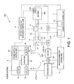
Fig. 1 is a view showing a configuration of an examination system for an electric vehicle according to one embodiment. -
Fig. 2 is a view showing a configuration of a circuit for battery charge and discharge according to the same embodiment. - Hereinafter, one embodiment of an
examination system 100 for an electric vehicle according to the present invention is described with reference to the drawings. - The
examination system 100 for the electric vehicle of this embodiment is used in order to perform an operating performance examination of amotor 200 that is mounted on an electric vehicle (EV) or a hybrid electric vehicle (HEV) and charge and discharge of abattery 300 that is mounted on the EV or HEV. - Specifically, as shown in
Fig. 1 , the system includes adynamometer 2 connected with an output shaft of themotor 200 to be examined, apower supply unit 3 for supplying electric power to themotor 200 and thedynamometer 2, a motor examination circuit L1 for supplying electric power of thepower supply unit 3 to thedynamometer 2 and themotor 200, a battery charge and discharge circuit L2 connected with thebattery 300 to be examined, for supplying electric power of thepower supply unit 3 to thebattery 300 or discharging electric power of thebattery 300, a battery motor connection circuit L3 connecting thebattery 300 with themotor 200, a circuit switching mechanism 4 for switching among the motor examination circuit L1, the battery charge and discharge circuit L2, and the battery motor connection circuit L3, a motorexamination control unit 5 for controlling the operating performance examination of themotor 200, a battery charge anddischarge control unit 6 for controlling charge and discharge of thebattery 300, and a higher-level control unit 7 for controlling the whole system. Thebattery 300 is an assembled battery comprised of a plurality of battery cells, such as lead rechargeable battery cells, which are connected in series or in parallel. Note that, each of the control units and other components shown inFigs. 1 and2 is connected through a signal line (each shown by a dashed line), and the control units and the other components connected with respective signal lines mutually transmit signals. Note that each of the control units and other components may be configured to mutually transmit the signals wirelessly. - The
dynamometer 2 has adrive shaft 21 that is mechanically coupled to anoutput shaft 201 of themotor 200 through a joint member (not illustrated) so as to be separatable, and may be an alternate current generator, for example. Thedynamometer 2 not only functions as an electric generator for generating power by themotor 200 rotating thedrive shaft 21, but also functions as an electric motor where thedrive shaft 21 rotated by supplying power from a power supply unit and themotor 200 coupled to thedrive shaft 21 is used as an electric generator. The drive of thedynamometer 2 is controlled by the motorexamination control unit 5. - Note that a
torque sensor 8 is provided to theoutput shaft 201 coupled to thedrive shaft 21 of thedynamometer 2, and a torque detection signal acquired by thetorque sensor 8 is outputted to the motorexamination control unit 5. - The
power supply unit 3 includes an AC/DC converter 31 for converting the alternate current power received from the electric power system into direct current power, a DC/AC inverter 32 for converting the direct current power converted by the AC/DC converter 31 into alternate current power and outputting it to thedynamometer 2, arechargeable unit 33, such as a capacitor, for accumulating the direct current power converted by the AC/DC converter 31, a DC/DC converter 34 for converting the direct current power charged by therechargeable unit 33 or the direct current power converted by the AC/DC converter 31 into a desirable voltage value, and a powersupply control unit 35 for controlling these components. - The power
supply control unit 35 controls the DC/DC converter 34 to adjust the direct current voltage output to themotor 200 or thebattery 300 from thepower supply unit 3. Specifically, in a motor examination mode (when the motor examination circuit L1 is closed by the circuit switching mechanism 4, as described later), the powersupply control unit 35 adjusts the direct current voltage value of thepower supply unit 3 which is outputted to the motor 200 (a motor inverter 210), whereas, in a battery charge and discharge mode (when the battery charge and discharge circuit L2 is closed by the circuit switching mechanism 4, as described later), the powersupply control unit 35 adjusts the direct current voltage value of thepower supply unit 3 which is outputted according to the desirable state of charge (SOC) of thebattery 300. The powersupply control unit 35 is a dedicated or general-purpose computer provided with a CPU, a memory, an input/output interface, etc. The powersupply control unit 35 controls the DC/DC converter 34 or other components when the CPU and peripheral equipment cooperate according to a power supply control program stored in the memory. - The motor examination circuit L 1 includes a dynamo power supply circuit L11 for conducting current between the AC/
DC converter 31 of thepower supply unit 3 and thedynamometer 2, and a motor power supply circuit L12 for conducting current between the DC/DC converter 34 of thepower supply unit 3, and themotor 200 and themotor inverter 210. - The battery charge and discharge circuit L2 is a circuit for conducting current between the DC/
DC converter 34 of thepower supply unit 3 andbattery 300. - The battery motor connection circuit L3 is a circuit for connecting the
battery 300, which is charged up and discharged down to the desirable SOC, with themotor 200. - The circuit switching mechanism 4 has a
switch 41 for switching between the motor examination circuit L1 and the battery charge and discharge circuit L2, and aswitch 42 for switching between on and off of the battery motor connection circuit L3. Theswitch 41 is provided intervening between the motor power supply circuit L12 of the motor examination circuit L1 and the battery charge and discharge circuit L2, and is controlled by a switchingmechanism control unit 71 set within the higher-level control unit 7. Moreover, theswitch 42 is provided intervening between the motor power supply circuit L12 of the motor examination circuit L1 and the battery motor connection circuit L3, and is controlled by the switchingmechanism control unit 71 set within the higher-level control unit 7. - The switching
mechanism control unit 71 can acquire an input signal, for example, from a user, and switch among the circuits L1, L2 and L3 to which current is conducted. Alternatively, a sensor (not illustrated) for detecting that thebattery 300 is connected with a power supply connector (not illustrated) provided in the battery charge and discharge circuit L2 may be provided to acquire the detection signal of this sensor and switch between the circuits L1 and L2 to which current is conducted. Moreover, the switchingmechanism control unit 71 detects that thebattery 300 reaches the desirable SOC by thebattery control unit 310 described later, sets theswitch 41 to be connected with neither one of the circuits L 1 and L2, and turns on theswitch 42 to close the battery motor connection circuit L3. - The motor
examination control unit 5 controls the whole motor examination in the electricvehicle examination system 100. The motorexamination control unit 5 is a dedicated or general-purpose computer provided with a CPU, a memory, an input/output interface, etc. The motorexamination control unit 5 controls thedynamometer 2, themotor 200 and other components by the CPU and peripheral equipment cooperating according to a motor examination control program stored in the memory. - Specifically, the motor
examination control unit 5 controls thedynamometer 2 and themotor 200 to perform the motor examination as follows. That is, the motorexamination control unit 5 finds an accelerator pedal depression amount and a brake pedal depression amount based on a vehicle driving pattern (for example, a traveling mode, such as 10.15 mode or 11 mode) which is inputted in advance to calculate a torque instruction (acceleration, deceleration), and controls drive of themotor 200 based on the torque instruction. Then, thetorque sensor 8 detects a load torque generated at this time, and a theoretical acceleration then generated is calculated based on an amount of inertia and a travel resistance of the electric vehicle which are set in advance. Then, thedynamometer 2 is controlled so that an engine speed equivalent to a theoretical vehicle traveling speed which can be obtained by integrating the theoretical accelerations is obtained. Simultaneously, a target speed contained in the vehicle driving pattern is compared with the theoretical vehicle traveling speed and the torque instruction value is controlled so that a difference between the target speed and the theoretical vehicle traveling speed becomes zero, to rotate themotor 200 by a rotation pattern according to the target speed pattern. - The battery charge and
discharge control unit 6 controls charge and discharge of the battery in the electricvehicle examination system 100, and is a dedicated or general-purpose computer provided with a CPU, a memory, an input/output interface, etc. The battery charge anddischarge control unit 6 controls thepower supply unit 3, thebattery 300 and other components by the CPU and peripheral equipment cooperating according to a battery charge and discharge control program stored in the memory. - Specifically, the battery charge and
discharge control unit 6 controls thepower supply unit 3 according to the instruction from the higher-level control unit 7 based on the battery information acquired from thebattery control unit 310 provided to thebattery 300 so that thebattery 300 reaches the desirable state of charge (SOC). That is, the higher-level control unit 7 outputs a voltage and current to be outputted from thepower supply unit 3 so that thebattery 300 reaches the desirable state of charge, to the powersupply control unit 35 via the battery charge anddischarge control unit 6. The powersupply control unit 35 which acquired the voltage data controls the DC/DC converter 34 of thepower supply unit 3 based on the voltage and current data. - Note that the battery control unit 310 (BCU) is a dedicated or general-purpose computer provided with a CPU, a memory, an input/output interface, etc. The
battery control unit 310 detects a current, a voltage and a temperature of thebattery 300, and based on them, calculates the state of charge (SOC) by the CPU and peripheral equipment cooperating according to a battery control program stored in the memory. - The higher-
level control unit 7 switches between a motor examination mode where a motor examination is performed using the electricvehicle examination system 100 and a battery charge and discharge mode where charge and discharge of the battery are performed. The higher-level control unit 7 is a dedicated or general-purpose computer provided with a CPU, a memory, an input/output interface, etc. The higher-level control unit 7 manages the motorexamination control unit 5 and the batterycharge control unit 6 and functions as the switchingmechanism control unit 71 for controlling the circuit switching mechanism 4, by the CPU and peripheral equipment cooperating according to a motor examination control program stored in the memory. Note that the higher-level control unit 7, the motorexamination control unit 5, and the battery charge anddischarge control unit 6 are configured so as to be able to perform wired or wireless communication with each other. - Specifically, the higher-
level control unit 7 operates the switchingmechanism control unit 71 to output to the switch 41 a control signal for switching theswitch 41 of the circuit switching mechanism 4 to switch between the motor examination mode and the battery charge and discharge mode. In the motor examination mode, the motor examination circuit L1 (specifically, the motor power supply circuit L12) is closed, and in the battery charge and discharge mode, the battery charge and discharge circuit L2 is closed. - In addition, as shown in
Fig. 2 , the electricvehicle examination system 100 of this embodiment also includes an on/offswitch 9 provided to the battery charge and discharge circuit L2, and aswitch control unit 72 for controlling on and off of the on/offswitch 9. - The on/off
switch 9 is provided on the battery side, rather than anoutput filter 341 comprised of an LC filter provided on the output side of the DC/DC converter 34. In this embodiment, the on/offswitch 9 is comprised ofswitches battery 300 and a line L22 connected with the negative terminal side of thebattery 300, respectively. - The
switch control unit 72 is set in the higher-level control unit 7, and before switching from the motor examination circuit L1 to the battery charge and discharge circuit L2, the on/offswitch 9 is turned off. Then, after switching from the motor examination circuit L1 to the battery charge and discharge circuit L2, when the output voltage of thepower supply unit 3 and the voltage between the terminals of thebattery 300 are the same, or when the difference becomes within a predetermined range, the on/offswitch 9 is turned on. - The
switch control unit 72 acquires the voltage detection signal from thevoltage sensor 10 that detects the voltage on the power supply unit side from the on/off switch 9 (i.e., the output voltage of the DC/DC converter 34 of the power supply unit 3), and also acquires a voltage signal indicative of the voltage on the battery side from the on/off switch 9 (i.e., the voltage between the terminals from theBMC 310 built in the battery 300). Then, Theswitch control unit 72 determines whether the output voltage of thepower supply unit 3 and the voltage between the terminals of thebattery 300 which are acquired are the same, or whether the difference of the voltages is within the predetermined range. Note that the phrase "within the predetermined range" used herein means a voltage difference which produces a current value such that the circuits in thebattery 300 are not cut off with a breaker 320 (for example, a fuse) built in thebattery 300. - If the difference is not within the predetermined range, the higher-
level control unit 7 then outputs the control signal to the battery charge anddischarge control unit 6, the battery charge anddischarge control unit 6 outputs the control signal to the powersupply control unit 35 for controlling the output voltage of thepower supply unit 3 so that the output voltage of thepower supply unit 3 becomes the voltage between the terminals of thebattery 300. Alternatively, the higher-level control unit 7 outputs the control signal to theBCU 310 for controlling the voltage between the terminals of the battery so that the voltage between the terminals of thebattery 300 becomes the output voltage of thepower supply unit 3. - Specifically, the higher-
level control unit 7 turns on the switches S1 and S3 shown inFig. 2 via the HCU, turns off the switch S2, and turns off theswitches battery cells 330 in the battery, electric charges are accumulated according to the capacity of thecapacitor 340 to produce a voltage (for example, 300V). Then, after the electric charges are accumulated in thecapacitor 340, the higher-level control unit 7 turns off the switch S1 via the HCU, turns on the switches S2 and S3, turns on theswitch 92, and turns off theswitch 91 to control the voltage of the DC/DC converter 34 so that the output voltage of the DC/DC converter 34 (the voltage between the output terminals of the converter 34) becomes the voltage of the capacitor 340 (for example, 300V). Then, after the output voltage of the DC/DC converter 34 and the voltage of thecapacitor 340 become the same voltage, theswitch 91 is turned on. - Note that, since the
switch 92 is turned on and theswitch 91 is turned off to control the output voltage of the DC/DC converter 34, a reference voltage of thecapacitor 340 and a reference voltage of the DC/DC converter 34 can be unified and, thus, the output voltage of the DC/DC converter 34 can easily be matched with the voltage of thecapacitor 340converter 34. Moreover, an inrush current into thebattery 300 can be prevented by the switches S1-S3, thebreaker 320, and thecapacitor 340, etc., which are provided in thebattery 300. - Moreover, since the electric
vehicle examination system 100 of this embodiment drives themotor 200 as an electric motor and drives thedynamometer 2 as a generator in the motor examination mode, regenerated power which is generated by thedynamometer 2 is charged into therechargeable unit 33 in the power supply unit 3 (an arrow B ofFig. 1 ). Similarly, in the motor examination mode, since thesystem 100 drives thedynamometer 2 as an electric motor and drives themotor 200 as a generator, regenerated power which is generated by themotor 200 is charged into therechargeable unit 33 in the power supply unit 3 (an arrow A ofFig. 1 ). Thus, since it is configured so that the regenerated power which is generated in the motor examination mode can be charged into therechargeable unit 33, energy can be circulated within the motor examination circuit L1, thereby achieving energy saving. - According to the electric
vehicle examination system 100 according to this embodiment configured in this way, the operating performance of themotor 200 and the like can be examined by the circuit switching mechanism 4 closing the motor examination circuit L1. Moreover, by closing the battery charge and discharge circuit L2 by the circuit switching mechanism 4, charge and discharge of thebattery 300 can be performed and it can be adjusted to the desirable state of charge (SOC). Thus, it is possible by the single system to perform the examination of themotor 200 mounted on the EV or HEV, and the charge and discharge of thebattery 300 mounted on the EV or HEV. Therefore, since there is no necessity of providing a power supply unit only for the battery charge and discharge, an equipment cost and an installation space can be reduced. Furthermore, the battery charge and discharge circuit L2 charges and discharges thebattery 300, and thebattery 300 charged up to the desirable state of charge (SOC) is connected with themotor 200 as it is by switching to the battery motor connection circuit L3, without moving thebattery 300, an examination of themotor 200 using thebattery 300 can also be performed. - Note that the present invention is not limited to the above embodiment.
- For example, a behavior program indicating an actual behavior of the battery may be stored in the memory of the power supply control unit, and the power supply unit for supplying power to the motor in a motor examining device may function as a battery imitated device. Note that the behavior program may be configured using data where the battery is modeled. The power supply control unit may control the DC/DC converter and other components based on this behavior program.
- Moreover, although the above embodiment uses the common power supply unit for the dynamometer and the motor, they may use different power supply units. In this case, one of the power supply units may be used for the charge and discharge of the battery.
- Furthermore, although the embodiment is configured so that the switches are controlled by the switching mechanism control unit, the circuit switching mechanism may include one or more mechanical switches and the user may manually switch the mechanical switches.
- Furthermore, the examination system for the electric vehicle of the above embodiment may be configured to perform a charge and discharge characteristic examination of the battery, a cycle life examination, etc. Specifically, a charge and discharge characteristic examination program or a cycle life examination program may be stored in the battery charge and discharge control unit, and an examination is performed by the CPU and peripheral equipment cooperating according to these programs.
- Moreover, each control unit of the above embodiment may be physically formed in a separate device for every function, and the control units may be configured to perform wired or wireless communication with each other. Alternatively, the higher-level control unit and the motor examination control unit or the battery charge and discharge control unit may be configured to be physically integrated. Moreover, it may be configured so that the function of each control unit is replaced with another control unit.
- The present invention is not limited to the above embodiment, and it may doubtlessly be modified variously without deviating from the scope of the present invention.
-
- 100
- Electric Vehicle Examination System
- 200
- Motor
- 201
- Output Shaft
- 300
- Battery
- 2
- Dynamometer
- 3
- Power Supply Unit
- 4
- Circuit Switching Mechanism
- L1
- Motor Examination Circuit
- L2
- Battery Charge And Discharge Circuit
- 71
- Switching Mechanism Control Unit
- 72
- Switch Control Unit
- 9
- On/Off Switch
Claims (4)
- An electric vehicle examination system, comprising:a dynamometer coupled to an output shaft of a motor that is used in an electric vehicle or a hybrid electric vehicle;a power supply unit for supplying power to the motor or the dynamometer;a motor examination circuit for supplying the power of the power supply unit to the dynamometer and the motor;a battery charge and discharge circuit connected with a battery that is used in the electric vehicle or the hybrid electric vehicle, for supplying the power of the power supply unit to the battery or discharging the power of the battery; anda circuit switching mechanism for switching between the motor examination circuit and the battery charge and discharge circuit.
- The electric vehicle examination system of Claim 1, comprising:an on/off switch provided to the battery charge and discharge circuit, for closing and opening the battery charge and discharge circuit; anda switch control unit for controlling on and off of the on/off switch,wherein the switch control unit turns on the on/off switch when a difference between a voltage of the power supply unit and a voltage of the battery becomes within a predetermined range.
- The electric vehicle examination system of Claim 2, wherein the switch control unit turns off the on/off switch before switching from the motor examination circuit to the battery charge and discharge circuit, and after changing from the motor examination circuit to the battery charge and discharge circuit, the switch control unit turns on the on/off switch when the difference between the voltage of the power supply unit and the voltage of the battery becomes within the predetermined range.
- The electric vehicle examination system of Claim 1, wherein the motor is driven as an electric motor, and the dynamometer is driven as a generator to charge power generated by the dynamometer into the power supply unit, or the dynamometer is driven as an electric motor, and the motor is driven as a generator to charge power generated by the motor into the power supply unit.
Applications Claiming Priority (1)
| Application Number | Priority Date | Filing Date | Title |
|---|---|---|---|
| US13/162,544 US9086333B2 (en) | 2011-06-16 | 2011-06-16 | Examination system for electric vehicle or hybrid electric vehicle |
Publications (3)
| Publication Number | Publication Date |
|---|---|
| EP2535695A2 true EP2535695A2 (en) | 2012-12-19 |
| EP2535695A3 EP2535695A3 (en) | 2018-01-03 |
| EP2535695B1 EP2535695B1 (en) | 2019-03-27 |
Family
ID=46642305
Family Applications (1)
| Application Number | Title | Priority Date | Filing Date |
|---|---|---|---|
| EP12004455.7A Not-in-force EP2535695B1 (en) | 2011-06-16 | 2012-06-13 | Test systems for electric vehicle and hybrid electric vehicle |
Country Status (5)
| Country | Link |
|---|---|
| US (1) | US9086333B2 (en) |
| EP (1) | EP2535695B1 (en) |
| JP (1) | JP5829567B2 (en) |
| KR (1) | KR101935975B1 (en) |
| CN (1) | CN102829979B (en) |
Cited By (1)
| Publication number | Priority date | Publication date | Assignee | Title |
|---|---|---|---|---|
| CN107521352A (en) * | 2017-06-26 | 2017-12-29 | 苏州赛帕太阳能科技有限公司 | A kind of automobile travel increasing apparatus and automotive powerplant |
Families Citing this family (30)
| Publication number | Priority date | Publication date | Assignee | Title |
|---|---|---|---|---|
| US9209628B2 (en) * | 2012-01-09 | 2015-12-08 | Johnson Controls Technology Llc | Systems and methods for de-energizing battery packs |
| US9553483B2 (en) * | 2013-03-01 | 2017-01-24 | Toshiba Corporation | System and method for limiting inrush current in solid state drives |
| CN103200268B (en) * | 2013-04-11 | 2016-01-20 | 山东大学 | The system and method for a kind of remote monitoring for electric automobile, upgrading and demarcation |
| CN103196676B (en) * | 2013-04-24 | 2015-05-06 | 山东大学 | Multi-system distributed electric vehicle performance test bed and multi-system distributed electric vehicle performance test method |
| CN103809120B (en) * | 2014-03-03 | 2016-11-02 | 广东机电职业技术学院 | A kind of test system and method for Weak mixed power automobile power system electric component |
| CN104143851A (en) * | 2014-08-07 | 2014-11-12 | 镇江洋溢汽车部件有限公司 | Electric vehicle charging device |
| CN106461505B (en) * | 2014-09-03 | 2019-11-19 | 株式会社堀场制作所 | Electric motor test macro |
| JP6505414B2 (en) * | 2014-10-31 | 2019-04-24 | 株式会社東芝 | Test apparatus and method for electric vehicle |
| CN104494412A (en) * | 2014-12-05 | 2015-04-08 | 芜湖中艺企业管理咨询有限公司 | Automotive hybrid power system |
| CN104515921B (en) * | 2015-01-29 | 2017-06-23 | 四川诚邦测控技术有限公司 | A kind of energy-saving electric power measurement of power comprehensive performance testing system based on energy feedback |
| CN104535328A (en) * | 2015-01-29 | 2015-04-22 | 四川诚邦测控技术有限公司 | Integrated experiment system based on new-energy vehicle driving motor performance detection |
| CN104535937B (en) * | 2015-01-29 | 2017-05-03 | 四川诚邦测控技术有限公司 | New energy power integrated test system based on digital simulated conditions |
| CN104701958A (en) * | 2015-03-27 | 2015-06-10 | 江苏天行健汽车科技有限公司 | Automatic wireless charging receiving and transmitting system of electric vehicle |
| CN104701959A (en) * | 2015-03-27 | 2015-06-10 | 江苏天行健汽车科技有限公司 | Wireless automatic charging system of electric vehicle |
| US10020759B2 (en) * | 2015-08-04 | 2018-07-10 | The Boeing Company | Parallel modular converter architecture for efficient ground electric vehicles |
| JP6421095B2 (en) * | 2015-08-05 | 2018-11-07 | 株式会社オートネットワーク技術研究所 | Repeater |
| CN105548763B (en) * | 2015-12-25 | 2019-02-26 | 北京新能源汽车股份有限公司 | Electric car and test macro for electric car |
| JP6724455B2 (en) * | 2016-03-22 | 2020-07-15 | トヨタ自動車株式会社 | Vehicle power supply system |
| CN105954676A (en) * | 2016-06-28 | 2016-09-21 | 无锡新大力电机有限公司 | Servo motor testing system |
| CN106526351B (en) * | 2016-09-29 | 2019-03-29 | 肇庆学院 | Hybrid power special-purpose vehicle regenerates auxiliary power testing stand and its test method |
| CN106494237A (en) * | 2016-09-30 | 2017-03-15 | 张家港长安大学汽车工程研究院 | Pure electric automobile regenerative braking energy reclaiming system and control method |
| KR102158258B1 (en) * | 2016-10-31 | 2020-09-21 | 주식회사 엘지화학 | Calculation method for current consumed rate per hour of drive apparatus using an electric dynamometer |
| CN107356436B (en) * | 2017-06-30 | 2019-12-27 | 同济大学 | Integrated automobile power system test bed |
| CN108051663A (en) * | 2017-11-13 | 2018-05-18 | 哈尔滨理工大学 | A kind of power system of electric automobile test platform and method based on LabVIEW |
| DE102018217965A1 (en) * | 2018-10-19 | 2020-04-23 | Aip Gmbh & Co. Kg | Roller dynamometer and method for operating a roller dynamometer |
| US11415484B2 (en) | 2019-07-11 | 2022-08-16 | Horiba Instruments Incorporated | Apparatus and method for testing automated vehicles via movable target body or electronic target simulator |
| CN110703095B (en) * | 2019-10-23 | 2021-10-12 | 江苏大学 | Road condition simulation loading test device and test method for electric vehicle driving motor |
| EP4106139A4 (en) * | 2020-02-27 | 2023-04-12 | Huawei Technologies Co., Ltd. | Connecting box, test bench of electric vehicle, and control method and device |
| DE102022103064B4 (en) | 2022-02-09 | 2022-11-17 | CUROCON GmbH | Test bench for testing a test vehicle |
| ES2953585B2 (en) * | 2022-03-30 | 2024-04-08 | Seat Sa | TEST BENCH AND METHOD FOR VEHICLES WITH ELECTRIC MOTOR |
Citations (2)
| Publication number | Priority date | Publication date | Assignee | Title |
|---|---|---|---|---|
| JP2001091410A (en) | 1999-09-27 | 2001-04-06 | Horiba Ltd | Electric car power system performance testing device and fuel cell performance testing device for electric car |
| JP2002090431A (en) | 2000-09-19 | 2002-03-27 | Sanyo Electric Co Ltd | System for testing cycle of battery for electric vehicle |
Family Cites Families (23)
| Publication number | Priority date | Publication date | Assignee | Title |
|---|---|---|---|---|
| US4313080A (en) * | 1978-05-22 | 1982-01-26 | Battery Development Corporation | Method of charge control for vehicle hybrid drive batteries |
| JPH07274309A (en) * | 1994-03-28 | 1995-10-20 | Toyota Autom Loom Works Ltd | Safety unit for charging vehicle mounted battery |
| JPH08248104A (en) * | 1995-03-10 | 1996-09-27 | Toyota Motor Corp | Motor performance test device |
| JP2973920B2 (en) * | 1995-05-24 | 1999-11-08 | トヨタ自動車株式会社 | Hybrid electric vehicle |
| JP3736300B2 (en) * | 2000-06-19 | 2006-01-18 | 株式会社日立製作所 | Automobile and power supply device thereof |
| JP4254693B2 (en) * | 2004-11-08 | 2009-04-15 | トヨタ自動車株式会社 | Driving device and automobile equipped with the same |
| JP4357411B2 (en) * | 2004-12-20 | 2009-11-04 | 株式会社日本自動車部品総合研究所 | Vehicle running simulation test system |
| JP4353093B2 (en) | 2004-12-24 | 2009-10-28 | 日産自動車株式会社 | Hybrid vehicle with variable voltage battery |
| US7448458B2 (en) * | 2005-10-04 | 2008-11-11 | John Fred Meyer | Electric vehicle reaction drive |
| JP2007116812A (en) | 2005-10-19 | 2007-05-10 | Fuji Heavy Ind Ltd | Inverter motor test device |
| JP4742827B2 (en) * | 2005-11-17 | 2011-08-10 | 株式会社明電舎 | Dynamometer for electric vehicles |
| JP4773848B2 (en) * | 2006-03-03 | 2011-09-14 | プライムアースEvエナジー株式会社 | Secondary battery charge / discharge control system, battery control device, and program |
| JP2007292654A (en) * | 2006-04-26 | 2007-11-08 | Toyota Motor Corp | Durability tester for on-board battery |
| JP4600934B2 (en) * | 2006-04-28 | 2010-12-22 | 株式会社エー・アンド・デイ | Chassis dynamometer |
| JP4552921B2 (en) * | 2006-10-25 | 2010-09-29 | トヨタ自動車株式会社 | Hybrid vehicle and control method thereof |
| JP2008191410A (en) * | 2007-02-05 | 2008-08-21 | Sumitomo Electric Ind Ltd | Optical connector |
| JP5022778B2 (en) * | 2007-05-28 | 2012-09-12 | 株式会社サトー知識財産研究所 | How to create a print sample form in a printer |
| CN100573177C (en) * | 2007-08-31 | 2009-12-23 | 奇瑞汽车股份有限公司 | A kind of hybrid power automobile drive electric motor test bench and method of testing |
| JP4513907B2 (en) * | 2008-06-30 | 2010-07-28 | トヨタ自動車株式会社 | Hybrid vehicle |
| JP4438887B1 (en) * | 2008-09-26 | 2010-03-24 | トヨタ自動車株式会社 | Electric vehicle and charging control method for electric vehicle |
| CN101660972B (en) * | 2009-06-26 | 2011-04-20 | 重庆长安汽车股份有限公司 | Hybrid power assembly performance matching test bench |
| JP2011038929A (en) * | 2009-08-12 | 2011-02-24 | Yokogawa Electric Corp | Testing apparatus for hybrid vehicle |
| TWI413340B (en) * | 2010-11-17 | 2013-10-21 | 財團法人工業技術研究院 | Method and apparatus to extend plug-in hybrid electric vehicular battery life |
-
2011
- 2011-06-16 US US13/162,544 patent/US9086333B2/en not_active Expired - Fee Related
-
2012
- 2012-04-05 JP JP2012086589A patent/JP5829567B2/en not_active Expired - Fee Related
- 2012-06-12 KR KR1020120062808A patent/KR101935975B1/en active IP Right Grant
- 2012-06-13 EP EP12004455.7A patent/EP2535695B1/en not_active Not-in-force
- 2012-06-18 CN CN201210205193.5A patent/CN102829979B/en not_active Expired - Fee Related
Patent Citations (2)
| Publication number | Priority date | Publication date | Assignee | Title |
|---|---|---|---|---|
| JP2001091410A (en) | 1999-09-27 | 2001-04-06 | Horiba Ltd | Electric car power system performance testing device and fuel cell performance testing device for electric car |
| JP2002090431A (en) | 2000-09-19 | 2002-03-27 | Sanyo Electric Co Ltd | System for testing cycle of battery for electric vehicle |
Cited By (2)
| Publication number | Priority date | Publication date | Assignee | Title |
|---|---|---|---|---|
| CN107521352A (en) * | 2017-06-26 | 2017-12-29 | 苏州赛帕太阳能科技有限公司 | A kind of automobile travel increasing apparatus and automotive powerplant |
| CN107521352B (en) * | 2017-06-26 | 2024-04-05 | 苏州赛帕太阳能科技有限公司 | Car increases journey ware and car power device |
Also Published As
| Publication number | Publication date |
|---|---|
| KR20120139559A (en) | 2012-12-27 |
| US20120323417A1 (en) | 2012-12-20 |
| EP2535695A3 (en) | 2018-01-03 |
| US9086333B2 (en) | 2015-07-21 |
| EP2535695B1 (en) | 2019-03-27 |
| JP2013003138A (en) | 2013-01-07 |
| JP5829567B2 (en) | 2015-12-09 |
| CN102829979A (en) | 2012-12-19 |
| CN102829979B (en) | 2017-04-12 |
| KR101935975B1 (en) | 2019-01-07 |
Similar Documents
| Publication | Publication Date | Title |
|---|---|---|
| EP2535695B1 (en) | Test systems for electric vehicle and hybrid electric vehicle | |
| KR100906907B1 (en) | Car battery management system | |
| CN102437596B (en) | Charging control method for super capacitor | |
| EP2555372B1 (en) | Power source device for vehicle | |
| JP4116609B2 (en) | Power supply control device, electric vehicle and battery control unit | |
| US9493090B2 (en) | Dynamic battery system voltage control through mixed dynamic series and parallel cell connections | |
| US20140176085A1 (en) | Battery controller of vehicle | |
| EP2869074B1 (en) | Device and method for calculating pre-charge resistance of battery pack | |
| CN105051552A (en) | Failure detection apparatus for voltage sensor | |
| CN107428254A (en) | The supply unit of vehicle | |
| US20110270489A1 (en) | Vehicle Electrical System | |
| CN103640493A (en) | Range extending system of electric automobile | |
| JP6186248B2 (en) | Inverter abnormality determination device | |
| WO2012132435A1 (en) | Vehicle power supply device | |
| US20140062409A1 (en) | Power supply system | |
| WO2015199178A1 (en) | Balance correction control device, balance correction system, and power storage system | |
| JP2011172340A (en) | Power supply device for vehicle | |
| KR20160049300A (en) | Voltage balancing apparatus and method between battery racks | |
| JP2004134221A (en) | Overcharge/overdischarge monitoring device for battery pack | |
| JP6322417B2 (en) | Voltage fluctuation control device | |
| US11686777B2 (en) | Power source control system for vehicle | |
| JP2011149726A (en) | Device for measuring state of charge | |
| US20230294531A1 (en) | Electric vehicle | |
| EP4180828A1 (en) | Deterioration diagnosis apparatus of battery and deterioration diagnosis method of battery | |
| JP2004312835A (en) | Charging/discharging controller of battery pack |
Legal Events
| Date | Code | Title | Description |
|---|---|---|---|
| PUAI | Public reference made under article 153(3) epc to a published international application that has entered the european phase |
Free format text: ORIGINAL CODE: 0009012 |
|
| AK | Designated contracting states |
Kind code of ref document: A2 Designated state(s): AL AT BE BG CH CY CZ DE DK EE ES FI FR GB GR HR HU IE IS IT LI LT LU LV MC MK MT NL NO PL PT RO RS SE SI SK SM TR |
|
| AX | Request for extension of the european patent |
Extension state: BA ME |
|
| RAP1 | Party data changed (applicant data changed or rights of an application transferred) |
Owner name: HORIBA INSTRUMENTS INCORPORATED Owner name: HORIBA, LTD. |
|
| PUAL | Search report despatched |
Free format text: ORIGINAL CODE: 0009013 |
|
| AK | Designated contracting states |
Kind code of ref document: A3 Designated state(s): AL AT BE BG CH CY CZ DE DK EE ES FI FR GB GR HR HU IE IS IT LI LT LU LV MC MK MT NL NO PL PT RO RS SE SI SK SM TR |
|
| AX | Request for extension of the european patent |
Extension state: BA ME |
|
| RIC1 | Information provided on ipc code assigned before grant |
Ipc: G01M 15/02 20060101AFI20171129BHEP Ipc: G01M 15/04 20060101ALI20171129BHEP |
|
| STAA | Information on the status of an ep patent application or granted ep patent |
Free format text: STATUS: REQUEST FOR EXAMINATION WAS MADE |
|
| 17P | Request for examination filed |
Effective date: 20180517 |
|
| RBV | Designated contracting states (corrected) |
Designated state(s): AL AT BE BG CH CY CZ DE DK EE ES FI FR GB GR HR HU IE IS IT LI LT LU LV MC MK MT NL NO PL PT RO RS SE SI SK SM TR |
|
| GRAP | Despatch of communication of intention to grant a patent |
Free format text: ORIGINAL CODE: EPIDOSNIGR1 |
|
| STAA | Information on the status of an ep patent application or granted ep patent |
Free format text: STATUS: GRANT OF PATENT IS INTENDED |
|
| INTG | Intention to grant announced |
Effective date: 20181010 |
|
| RAP1 | Party data changed (applicant data changed or rights of an application transferred) |
Owner name: HORIBA, LTD. Owner name: HORIBA INSTRUMENTS INCORPORATED |
|
| RIN1 | Information on inventor provided before grant (corrected) |
Inventor name: SASAHARA, KAZUHISA Inventor name: YAO, MASAHIRO Inventor name: KOMADA, MINEYUKI Inventor name: RUMER, RICHARD Inventor name: WITTER, STEVE |
|
| GRAS | Grant fee paid |
Free format text: ORIGINAL CODE: EPIDOSNIGR3 |
|
| GRAA | (expected) grant |
Free format text: ORIGINAL CODE: 0009210 |
|
| STAA | Information on the status of an ep patent application or granted ep patent |
Free format text: STATUS: THE PATENT HAS BEEN GRANTED |
|
| AK | Designated contracting states |
Kind code of ref document: B1 Designated state(s): AL AT BE BG CH CY CZ DE DK EE ES FI FR GB GR HR HU IE IS IT LI LT LU LV MC MK MT NL NO PL PT RO RS SE SI SK SM TR |
|
| REG | Reference to a national code |
Ref country code: GB Ref legal event code: FG4D |
|
| REG | Reference to a national code |
Ref country code: CH Ref legal event code: EP |
|
| REG | Reference to a national code |
Ref country code: DE Ref legal event code: R096 Ref document number: 602012058186 Country of ref document: DE |
|
| REG | Reference to a national code |
Ref country code: AT Ref legal event code: REF Ref document number: 1113675 Country of ref document: AT Kind code of ref document: T Effective date: 20190415 |
|
| REG | Reference to a national code |
Ref country code: IE Ref legal event code: FG4D |
|
| PG25 | Lapsed in a contracting state [announced via postgrant information from national office to epo] |
Ref country code: NO Free format text: LAPSE BECAUSE OF FAILURE TO SUBMIT A TRANSLATION OF THE DESCRIPTION OR TO PAY THE FEE WITHIN THE PRESCRIBED TIME-LIMIT Effective date: 20190627 Ref country code: SE Free format text: LAPSE BECAUSE OF FAILURE TO SUBMIT A TRANSLATION OF THE DESCRIPTION OR TO PAY THE FEE WITHIN THE PRESCRIBED TIME-LIMIT Effective date: 20190327 Ref country code: FI Free format text: LAPSE BECAUSE OF FAILURE TO SUBMIT A TRANSLATION OF THE DESCRIPTION OR TO PAY THE FEE WITHIN THE PRESCRIBED TIME-LIMIT Effective date: 20190327 Ref country code: LT Free format text: LAPSE BECAUSE OF FAILURE TO SUBMIT A TRANSLATION OF THE DESCRIPTION OR TO PAY THE FEE WITHIN THE PRESCRIBED TIME-LIMIT Effective date: 20190327 |
|
| REG | Reference to a national code |
Ref country code: NL Ref legal event code: MP Effective date: 20190327 |
|
| PG25 | Lapsed in a contracting state [announced via postgrant information from national office to epo] |
Ref country code: LV Free format text: LAPSE BECAUSE OF FAILURE TO SUBMIT A TRANSLATION OF THE DESCRIPTION OR TO PAY THE FEE WITHIN THE PRESCRIBED TIME-LIMIT Effective date: 20190327 Ref country code: HR Free format text: LAPSE BECAUSE OF FAILURE TO SUBMIT A TRANSLATION OF THE DESCRIPTION OR TO PAY THE FEE WITHIN THE PRESCRIBED TIME-LIMIT Effective date: 20190327 Ref country code: NL Free format text: LAPSE BECAUSE OF FAILURE TO SUBMIT A TRANSLATION OF THE DESCRIPTION OR TO PAY THE FEE WITHIN THE PRESCRIBED TIME-LIMIT Effective date: 20190327 Ref country code: GR Free format text: LAPSE BECAUSE OF FAILURE TO SUBMIT A TRANSLATION OF THE DESCRIPTION OR TO PAY THE FEE WITHIN THE PRESCRIBED TIME-LIMIT Effective date: 20190628 Ref country code: BG Free format text: LAPSE BECAUSE OF FAILURE TO SUBMIT A TRANSLATION OF THE DESCRIPTION OR TO PAY THE FEE WITHIN THE PRESCRIBED TIME-LIMIT Effective date: 20190627 Ref country code: RS Free format text: LAPSE BECAUSE OF FAILURE TO SUBMIT A TRANSLATION OF THE DESCRIPTION OR TO PAY THE FEE WITHIN THE PRESCRIBED TIME-LIMIT Effective date: 20190327 |
|
| REG | Reference to a national code |
Ref country code: AT Ref legal event code: MK05 Ref document number: 1113675 Country of ref document: AT Kind code of ref document: T Effective date: 20190327 |
|
| PG25 | Lapsed in a contracting state [announced via postgrant information from national office to epo] |
Ref country code: ES Free format text: LAPSE BECAUSE OF FAILURE TO SUBMIT A TRANSLATION OF THE DESCRIPTION OR TO PAY THE FEE WITHIN THE PRESCRIBED TIME-LIMIT Effective date: 20190327 Ref country code: EE Free format text: LAPSE BECAUSE OF FAILURE TO SUBMIT A TRANSLATION OF THE DESCRIPTION OR TO PAY THE FEE WITHIN THE PRESCRIBED TIME-LIMIT Effective date: 20190327 Ref country code: SK Free format text: LAPSE BECAUSE OF FAILURE TO SUBMIT A TRANSLATION OF THE DESCRIPTION OR TO PAY THE FEE WITHIN THE PRESCRIBED TIME-LIMIT Effective date: 20190327 Ref country code: IT Free format text: LAPSE BECAUSE OF FAILURE TO SUBMIT A TRANSLATION OF THE DESCRIPTION OR TO PAY THE FEE WITHIN THE PRESCRIBED TIME-LIMIT Effective date: 20190327 Ref country code: RO Free format text: LAPSE BECAUSE OF FAILURE TO SUBMIT A TRANSLATION OF THE DESCRIPTION OR TO PAY THE FEE WITHIN THE PRESCRIBED TIME-LIMIT Effective date: 20190327 Ref country code: CZ Free format text: LAPSE BECAUSE OF FAILURE TO SUBMIT A TRANSLATION OF THE DESCRIPTION OR TO PAY THE FEE WITHIN THE PRESCRIBED TIME-LIMIT Effective date: 20190327 Ref country code: AL Free format text: LAPSE BECAUSE OF FAILURE TO SUBMIT A TRANSLATION OF THE DESCRIPTION OR TO PAY THE FEE WITHIN THE PRESCRIBED TIME-LIMIT Effective date: 20190327 Ref country code: PT Free format text: LAPSE BECAUSE OF FAILURE TO SUBMIT A TRANSLATION OF THE DESCRIPTION OR TO PAY THE FEE WITHIN THE PRESCRIBED TIME-LIMIT Effective date: 20190727 |
|
| PG25 | Lapsed in a contracting state [announced via postgrant information from national office to epo] |
Ref country code: SM Free format text: LAPSE BECAUSE OF FAILURE TO SUBMIT A TRANSLATION OF THE DESCRIPTION OR TO PAY THE FEE WITHIN THE PRESCRIBED TIME-LIMIT Effective date: 20190327 Ref country code: PL Free format text: LAPSE BECAUSE OF FAILURE TO SUBMIT A TRANSLATION OF THE DESCRIPTION OR TO PAY THE FEE WITHIN THE PRESCRIBED TIME-LIMIT Effective date: 20190327 |
|
| PG25 | Lapsed in a contracting state [announced via postgrant information from national office to epo] |
Ref country code: AT Free format text: LAPSE BECAUSE OF FAILURE TO SUBMIT A TRANSLATION OF THE DESCRIPTION OR TO PAY THE FEE WITHIN THE PRESCRIBED TIME-LIMIT Effective date: 20190327 Ref country code: IS Free format text: LAPSE BECAUSE OF FAILURE TO SUBMIT A TRANSLATION OF THE DESCRIPTION OR TO PAY THE FEE WITHIN THE PRESCRIBED TIME-LIMIT Effective date: 20190727 |
|
| REG | Reference to a national code |
Ref country code: DE Ref legal event code: R097 Ref document number: 602012058186 Country of ref document: DE |
|
| PG25 | Lapsed in a contracting state [announced via postgrant information from national office to epo] |
Ref country code: DK Free format text: LAPSE BECAUSE OF FAILURE TO SUBMIT A TRANSLATION OF THE DESCRIPTION OR TO PAY THE FEE WITHIN THE PRESCRIBED TIME-LIMIT Effective date: 20190327 Ref country code: MC Free format text: LAPSE BECAUSE OF FAILURE TO SUBMIT A TRANSLATION OF THE DESCRIPTION OR TO PAY THE FEE WITHIN THE PRESCRIBED TIME-LIMIT Effective date: 20190327 |
|
| REG | Reference to a national code |
Ref country code: CH Ref legal event code: PL |
|
| PLBE | No opposition filed within time limit |
Free format text: ORIGINAL CODE: 0009261 |
|
| STAA | Information on the status of an ep patent application or granted ep patent |
Free format text: STATUS: NO OPPOSITION FILED WITHIN TIME LIMIT |
|
| PG25 | Lapsed in a contracting state [announced via postgrant information from national office to epo] |
Ref country code: SI Free format text: LAPSE BECAUSE OF FAILURE TO SUBMIT A TRANSLATION OF THE DESCRIPTION OR TO PAY THE FEE WITHIN THE PRESCRIBED TIME-LIMIT Effective date: 20190327 |
|
| 26N | No opposition filed |
Effective date: 20200103 |
|
| REG | Reference to a national code |
Ref country code: BE Ref legal event code: MM Effective date: 20190630 |
|
| PG25 | Lapsed in a contracting state [announced via postgrant information from national office to epo] |
Ref country code: TR Free format text: LAPSE BECAUSE OF FAILURE TO SUBMIT A TRANSLATION OF THE DESCRIPTION OR TO PAY THE FEE WITHIN THE PRESCRIBED TIME-LIMIT Effective date: 20190327 |
|
| PG25 | Lapsed in a contracting state [announced via postgrant information from national office to epo] |
Ref country code: IE Free format text: LAPSE BECAUSE OF NON-PAYMENT OF DUE FEES Effective date: 20190613 |
|
| PG25 | Lapsed in a contracting state [announced via postgrant information from national office to epo] |
Ref country code: LI Free format text: LAPSE BECAUSE OF NON-PAYMENT OF DUE FEES Effective date: 20190630 Ref country code: LU Free format text: LAPSE BECAUSE OF NON-PAYMENT OF DUE FEES Effective date: 20190613 Ref country code: CH Free format text: LAPSE BECAUSE OF NON-PAYMENT OF DUE FEES Effective date: 20190630 Ref country code: BE Free format text: LAPSE BECAUSE OF NON-PAYMENT OF DUE FEES Effective date: 20190630 |
|
| PG25 | Lapsed in a contracting state [announced via postgrant information from national office to epo] |
Ref country code: CY Free format text: LAPSE BECAUSE OF FAILURE TO SUBMIT A TRANSLATION OF THE DESCRIPTION OR TO PAY THE FEE WITHIN THE PRESCRIBED TIME-LIMIT Effective date: 20190327 |
|
| PG25 | Lapsed in a contracting state [announced via postgrant information from national office to epo] |
Ref country code: MT Free format text: LAPSE BECAUSE OF FAILURE TO SUBMIT A TRANSLATION OF THE DESCRIPTION OR TO PAY THE FEE WITHIN THE PRESCRIBED TIME-LIMIT Effective date: 20190327 Ref country code: HU Free format text: LAPSE BECAUSE OF FAILURE TO SUBMIT A TRANSLATION OF THE DESCRIPTION OR TO PAY THE FEE WITHIN THE PRESCRIBED TIME-LIMIT; INVALID AB INITIO Effective date: 20120613 |
|
| PGFP | Annual fee paid to national office [announced via postgrant information from national office to epo] |
Ref country code: FR Payment date: 20210622 Year of fee payment: 10 Ref country code: DE Payment date: 20210628 Year of fee payment: 10 |
|
| PGFP | Annual fee paid to national office [announced via postgrant information from national office to epo] |
Ref country code: GB Payment date: 20210623 Year of fee payment: 10 |
|
| PG25 | Lapsed in a contracting state [announced via postgrant information from national office to epo] |
Ref country code: MK Free format text: LAPSE BECAUSE OF FAILURE TO SUBMIT A TRANSLATION OF THE DESCRIPTION OR TO PAY THE FEE WITHIN THE PRESCRIBED TIME-LIMIT Effective date: 20190327 |
|
| REG | Reference to a national code |
Ref country code: DE Ref legal event code: R119 Ref document number: 602012058186 Country of ref document: DE |
|
| GBPC | Gb: european patent ceased through non-payment of renewal fee |
Effective date: 20220613 |
|
| PG25 | Lapsed in a contracting state [announced via postgrant information from national office to epo] |
Ref country code: FR Free format text: LAPSE BECAUSE OF NON-PAYMENT OF DUE FEES Effective date: 20220630 |
|
| PG25 | Lapsed in a contracting state [announced via postgrant information from national office to epo] |
Ref country code: GB Free format text: LAPSE BECAUSE OF NON-PAYMENT OF DUE FEES Effective date: 20220613 Ref country code: DE Free format text: LAPSE BECAUSE OF NON-PAYMENT OF DUE FEES Effective date: 20230103 |