EP2535689A1 - Method and device for measurement with an IR imaging device - Google Patents
Method and device for measurement with an IR imaging device Download PDFInfo
- Publication number
- EP2535689A1 EP2535689A1 EP11170287A EP11170287A EP2535689A1 EP 2535689 A1 EP2535689 A1 EP 2535689A1 EP 11170287 A EP11170287 A EP 11170287A EP 11170287 A EP11170287 A EP 11170287A EP 2535689 A1 EP2535689 A1 EP 2535689A1
- Authority
- EP
- European Patent Office
- Prior art keywords
- measuring
- imaging device
- infrared imaging
- measurements
- measuring device
- Prior art date
- Legal status (The legal status is an assumption and is not a legal conclusion. Google has not performed a legal analysis and makes no representation as to the accuracy of the status listed.)
- Withdrawn
Links
Images

Classifications
-
- G—PHYSICS
- G01—MEASURING; TESTING
- G01J—MEASUREMENT OF INTENSITY, VELOCITY, SPECTRAL CONTENT, POLARISATION, PHASE OR PULSE CHARACTERISTICS OF INFRARED, VISIBLE OR ULTRAVIOLET LIGHT; COLORIMETRY; RADIATION PYROMETRY
- G01J5/00—Radiation pyrometry, e.g. infrared or optical thermometry
-
- G—PHYSICS
- G01—MEASURING; TESTING
- G01J—MEASUREMENT OF INTENSITY, VELOCITY, SPECTRAL CONTENT, POLARISATION, PHASE OR PULSE CHARACTERISTICS OF INFRARED, VISIBLE OR ULTRAVIOLET LIGHT; COLORIMETRY; RADIATION PYROMETRY
- G01J5/00—Radiation pyrometry, e.g. infrared or optical thermometry
- G01J5/02—Constructional details
-
- G—PHYSICS
- G01—MEASURING; TESTING
- G01J—MEASUREMENT OF INTENSITY, VELOCITY, SPECTRAL CONTENT, POLARISATION, PHASE OR PULSE CHARACTERISTICS OF INFRARED, VISIBLE OR ULTRAVIOLET LIGHT; COLORIMETRY; RADIATION PYROMETRY
- G01J5/00—Radiation pyrometry, e.g. infrared or optical thermometry
- G01J2005/0077—Imaging
Definitions
- the present invention relates to a device for measuring at least two properties of an object, said device comprising a first measuring device for measuring at least one physical property of an object and infrared imaging device for measuring at least one thermal property of an object.
- the invention further relates to a method for measuring at least two properties of an obj ect.
- the object of the present invention is to eliminate or at least to minimize the problems described above. This is achieved through a device according to the appended claim i, wherein a first measuring device and an infrared imaging device are arranged to simultaneously measure at least one physical property and a temperature of an object. Thereby, a more comprehensive analysis of an object can be performed, relating a temperature of the object to a physical property measured at the same time. Thanks to the combination and timing of measurements, a temperature corresponding in time to a specific physical property can be determined, giving a more comprehensive image of the thermal response of the component or circuit to the application of a voltage or current, for instance.
- a synchronizing system can use a suitable trigger rate from any of the measuring devices to determine when measurements are to be performed at each of the measuring devices, and data can be stored in such a way that a correlation between their timing can be recorded.
- a natural clock rate of an infrared (IR) imaging device can be used to synchronize measuring of the physical property recorded by a first measuring device, or vice versa, allowing for a precise matching of the thermal behavior with the physical behavior.
- Fig. 1 shows a measuring device 1 according to a preferred embodiment of the invention with a first measuring device 2, for instance in the form of an oscilloscope, and an infrared (IR) imaging device 3, for instance in the form of an IR system, arranged to perform electronic measurements by means of a probe 25 and an IR imaging device 34, respectively, for measuring properties of an object 5.
- Said probe 25 is equipped with a sensor/detector arranged to perform a measurement and transfer measurement data in the form of an electrical signal from said sensor/detector to said first measuring device (2) by means of the probe (25).
- an oscilloscope 2 comprises a vertical system 22 connected to the probe 25 and receiving signals from it, and is arranged to process said signals by means of an attenuator 221 and a vertical amplifier 222 to achieve signals more suitable for display and storage.
- the vertical system 22 is also connected to an acquisition system 21 for receiving signals, converting them from analogue to digital signals in a converter 211 and storing in a memory unit 212.
- a processing unit 213 is also provided for interacting with the memory unit 212 to further process the digital signals in suitable ways and storing processed signals after such procedure.
- the probe 25 is arranged to measure at least one physical property of the object 5 and to represent said physical property by means of an electric signal that can be transferred to the first measuring device 2.
- the physical property can be an electrical property, such as a current or voltage for instance, but can also be a property such as a pressure, speed or rotational velocity.
- the probe 25 can be arranged to perform measurements of more than one physical property depending on the situation, but in other embodiments it may be more advantageous to provide a plurality of probes 25 to measure different physical properties as is deemed suitable.
- a synchronizing system 41 for synchronizing operation of the device 1 is connected to the vertical system 22 to receive input and to process these further in a horizontal system 42, giving input to the converter 211 and the memory unit 212.
- the IR system 3 comprises an IR imaging device 34 for performing temperature measurements of the object 5 and transmitting signals, for instance in the form of thermal images, to an image acquisition unit 312 and image processing unit 313 mounted in an imaging device system 31.
- Said imaging device system 31 is also connected to the memory unit 212 for storing and processing IR images in a manner similar to that for electrical data captured by the probe 25 and processed by the oscilloscope 2, and to the synchronizing system 41.
- a digital display system 23 for displaying captured data to a user of the system, there may be provided a digital display system 23 in connection with the memory unit 212, and further a display unit 24, where data can be shown in the form of graphs, images or other suitable representations.
- a multimeter tool, data logger or other instrument with a recording device suitable for measuring physical properties can be used, or a plurality of different instruments measuring different physical properties.
- An object 5 to be measured is placed in a suitable location where both the infrared imaging device 34 and the probe 25 can be used.
- a user can interact with a man-machine interface (not shown) to determine which physical property is to be measured by the probe 25, control parameters relating to the operation of the infrared imaging device 34, and if desired a clock rate used with the synchronizing system 41 for timing the measurements.
- a current or voltage with suitable properties can be applied and a reaction to this application by the object 5 can be recorded by the probe 25 and transmitted in the form of a plurality of signals to the vertical system 22, where the signals may be processed and amplified in order to be more easily analyzed and viewed at later stages.
- the infrared imaging device 34 may detect thermal energy emitted from the object 5 to form a series of infrared images or other data corresponding to a temperature measurement, and transmitting said images or other data in the form of signals to the imaging device system 31.
- the synchronizing system 41 controls the frequency and/or timing of measurements to be recorded by the measurement device 1 so that from a continuous stream of signals relating to a physical property or a temperature signals can be selected that have been recorded at a specific point in time. Such signals can constitute a pair of signals and be stored by the memory unit 212 for simultaneous display in the display unit 24.
- the synchronization performed by the synchronizing system 41 can be performed differently depending on, among others, the object 5 to be measured, properties of the first measuring device 2, properties of the infrared imaging device 3, or display and calculation preferences by the user of the system.
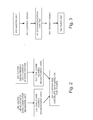
- Fig. 2 and fig. 3 relate to synchronization of measurements, wherein the measurements that are to be synchronized, in order to be performed simultaneously, comprise: measurements of at least one physical property of an object (5), said physical property being represented by an electrical signal; and measurements of a thermal property of the same object (5).
- Fig. 3 shows a block diagram representing synchronization according to alternative exemplary embodiments wherein one of two measuring device acts as a master unit 300, and a slave unit 304.
- the two measuring devices may for instance be the first measuring device 2 and the second measuring device 3, wherein either measuring device may act as the master unit 300 or the slave unit 304 according to different embodiments.
- the master unit 300 controls the measurements performed by the slave unit 304 by transmitting a control signal 301 to the synchronizing system 41, whereby the synchronization system 41 processes the received control signal 301 and transmits a trigger signal 303 to the slave unit 304, the trigger signal indicating the frequency and/or timing of measurements to be performed by the slave unit 304, in order for the measurements of the slave unit 304 to be performed simultaneously with the measurements of the master unit 300.
- Alternative embodiments of this synchronization method are presented below in embodiments 1, 2 and 3.
- the synchronization is dependent on a periodic signal in the first measuring device 2, for instance an oscilloscope.
- the first measuring device 2 acts as the master unit 300 and the periodic signal is transmitted as a control signal 301 to the synchronization system 41.
- the infrared imaging device in the form of an IR system 3 acts as a slave unit 304 to the first measuring device 2.
- a periodic signal reaches a specified value, such as a peak value for instance
- a trigger signal 303 is sent from the synchronization system 41 to create an image at the IR system 3.
- the image is recorded together with a simultaneous measurement of the first measuring device 2.
- the first measuring device 2 gives an analogue signal of the measurements performed but only data corresponding to the time of the determined point on the periodic signal is stored, together with the image of the IR system 3 at that time.
- the IR system 3 comprises a high-end imaging device 34, which generally gives the opportunity to have the imaging device 34 controlled by a periodicity given by another device such as an oscilloscope 2.
- the measuring rate can in this embodiment be chosen to match an electrical behavior of the object 5, such as for instance a frequency to be measured, and the infrared imaging device 34 can be matched to this rate.
- the imaging device 34 is of a more conventional type
- a second beneficial embodiment can be used wherein the synchronizing system 41 allows a frame rate of the IR imaging device 34 to control the measurements of the first measuring device 2.
- the IR system 3 acts as the master unit 300 according to this embodiment
- the control signal 301 transmitted to the synchronization system 41 is represented as the frame rate of the IR imaging device 34.
- the imaging device 34 collects a series of images at a suitable frame rate, and the synchronizing system 41 synchronizes the first measuring device 2 by transmitting a trigger signal 303 to acquire a measurement corresponding to the time instance when each of these images is captured.
- the first measuring device 2 is a slave to the IR system 3 and only one analogue data point is created for each image from the IR system 3.
- the frame rate of the IR imaging device 34 is used by the synchronizing system 41 to determine a data acquisition rate of the device 1.
- the IR system acts as the master unit 300 that transmits a control signal 301 in the form of the frame rate of the IR imaging device 34 to the synchronization system 41, and the first measuring device acts as the slave unit 304.
- the synchronization unit 41 further transmits a trigger signal 303 based on the received control signal 301 to the slave unit 304.
- an acquisition clock is created for the first measuring device 2 with a clock rate corresponding to the frame rate of the imaging device 34.
- a trigger signal 303 is transmitted to the IR imaging device 34 to acquire measurement data (capture images) at a rate corresponding to the clock rate of the acquisition clock.
- the first device 2 and infrared imaging device 3 work independently with separate triggers but at the same clock rate or frame rate for the acquisition of measurements.
- the imaging device 34 is thereby determining and limiting the rates that are suitable in this embodiment, but a number of analogue data points can be created by the first measuring device 2 for each of the images created by the imaging device 34.
- it is a thermal behavior of the object 5 rather than a physical behavior that determines when it is suitable to perform the measurement, and the data from the first measuring device 2, for instance an oscilloscope, serve to display the physical properties corresponding to these thermal properties.
- a time stamping synchronization can be used, where the synchronizing system 41 allows both the first measuring device 2 and the IR system 3 to measure data and records the timing of each measurement.
- This embodiment is shown in Fig. 2 .
- none of the devices acts as a master unit 300.
- each image acquired 201 by the IR system 3 is stored together with a time stamp 203 identifying when the image was created and in parallel analogue data points acquired 200 by the first measuring device 2 are stored and time stamped 202.
- the time stamped measurement data from both measurement devise 2,3 are received in the synchronization system 41, where the time stamps are compared based on the time stamp information in order to find correlation 204 between the measurement data from both devices 2, 3.
- the correlation between an image and the analogue data points created at approximately the same time is smaller than by the other embodiments described above, and an interpolation of the analogue signal may be required to determine a measurement of the first measuring device 2 at precisely the time instance when a particular image was created.
- the embodiments described above differ in the amount of analogue data captured by the first measuring device 2 for each image from the IR system 3. Depending on the application where the device 1 is used, it may be more suitable to collect a higher amount of analogue data, or it may conversely be more suitable to achieve a very high correlation between the timing of the measurements of the measuring devices 2,3 and thus have only one data point for each image.
- Other adaptations within the scope of the claims are of course also readily apparent to the person skilled in the art. As a result, a comprehensive analysis of a physical and a thermal behavior of the object 5 can be achieved.
- an analysis can be performed in the processing unit 213 of the device 1 to evaluate properties and performance of the object 5 during the measurements.
- the images and data points can also be displayed in a combined way in the display 24 for viewing by the user, allowing her or him to analyze the object 5 and to perform suitable tests to view its physical and thermal properties as desired.
- To display the measured data together is advantageous in that it allows the user to assess the properties of an object and the correlation and combined impact of the different measured properties easily, and to achieve and maintain an overview of the measuring as well as the object being measured.
- Data can also be extracted from the memory unit 212 to a separate processing unit (not shown) for further analysis.
Landscapes
- Physics & Mathematics (AREA)
- General Physics & Mathematics (AREA)
- Spectroscopy & Molecular Physics (AREA)
- Radiation Pyrometers (AREA)
Abstract
The present invention relates to a method and device for measuring at least two properties of an object, said device comprising a first measuring device for measuring at least one physical property of an object and an infrared imaging device for measuring at least one thermal property of an object, and wherein said first measuring device and said infrared imaging device are arranged to be synchronized to perform simultaneous measurements of an object.
Description
- The present invention relates to a device for measuring at least two properties of an object, said device comprising a first measuring device for measuring at least one physical property of an object and infrared imaging device for measuring at least one thermal property of an object. The invention further relates to a method for measuring at least two properties of an obj ect.
- In many industrial applications, such as during manufacture of electronic components, it is important to supervise the production by measuring properties of the components, among others. Especially with regards to the design phase of electronic circuits, electronic properties are often measured to assure proper functioning of the components manufactured.
- At present, such measurements are performed for instance by using an oscilloscope for monitoring electrical properties such as current, voltage or frequency of the components or circuits. A comprehensive analysis is, however, difficult to achieve using only these electrical properties, resulting in the risk for imperfections or errors in produced components or circuits. Such errors can severely decrease performance of products, resulting in the need for replacement or repair far earlier than would have been the case had all components been fully functional to begin with.
- Other areas where improved measurements of properties of an object are desired are for instance when investigating load imbalances of a device or component, when detecting energy consumption and energy efficiency, or when finding defective areas of a material or analyzing a behavior of solar cells and the like to determine how they perform in a given situation.
- There is therefore a need for performing a more versatile analysis of electronic components and circuits, both at a manufacturing stage and later as a troubleshooting tool for determining errors in a finished product.
- Prior art methods within the area are shown by
US4,593,207 ,US3,456,111 andUS3,820,135 . None of these, however, disclose methods or devices suitable for a more comprehensive analysis of the properties of a specific object. - Another prior art device is shown by the SUSolution Analyzer device DF1100 produced by NEC. This device does not disclose a device suitable for a sufficiently thorough analysis of the properties of an object and does not enable a suitable presentation of measuring data to assess said properties.
- The object of the present invention is to eliminate or at least to minimize the problems described above. This is achieved through a device according to the appended claim i, wherein a first measuring device and an infrared imaging device are arranged to simultaneously measure at least one physical property and a temperature of an object. Thereby, a more comprehensive analysis of an object can be performed, relating a temperature of the object to a physical property measured at the same time. Thanks to the combination and timing of measurements, a temperature corresponding in time to a specific physical property can be determined, giving a more comprehensive image of the thermal response of the component or circuit to the application of a voltage or current, for instance.
- Depending on the properties of an object to be analyzed or on the properties of the first measuring device and infrared imaging device, a synchronizing system can use a suitable trigger rate from any of the measuring devices to determine when measurements are to be performed at each of the measuring devices, and data can be stored in such a way that a correlation between their timing can be recorded. Thereby, according to exemplary embodiments, a natural clock rate of an infrared (IR) imaging device can be used to synchronize measuring of the physical property recorded by a first measuring device, or vice versa, allowing for a precise matching of the thermal behavior with the physical behavior.
- Further advantages and benefits of embodiments of the invention will become readily apparent to the person skilled in the art in view of the detailed description below.
- The invention will now be described in more detail with reference to the appended drawings, wherein:
-
Fig. 1 shows a schematic view of a measuring device according to an exemplary embodiment. -
Fig. 2 is a block diagram representing synchronization according to an exemplary embodiment. -
Fig. 3 is a block diagram representing synchronization according to alternative exemplary embodiments. -
Fig. 1 shows a measuring device 1 according to a preferred embodiment of the invention with a first measuring device 2, for instance in the form of an oscilloscope, and an infrared (IR) imaging device 3, for instance in the form of an IR system, arranged to perform electronic measurements by means of aprobe 25 and anIR imaging device 34, respectively, for measuring properties of an object 5. Saidprobe 25 is equipped with a sensor/detector arranged to perform a measurement and transfer measurement data in the form of an electrical signal from said sensor/detector to said first measuring device (2) by means of the probe (25). - According to an exemplary embodiment, an oscilloscope 2 comprises a
vertical system 22 connected to theprobe 25 and receiving signals from it, and is arranged to process said signals by means of anattenuator 221 and avertical amplifier 222 to achieve signals more suitable for display and storage. Thevertical system 22 is also connected to anacquisition system 21 for receiving signals, converting them from analogue to digital signals in aconverter 211 and storing in amemory unit 212. Aprocessing unit 213 is also provided for interacting with thememory unit 212 to further process the digital signals in suitable ways and storing processed signals after such procedure. Theprobe 25 is arranged to measure at least one physical property of the object 5 and to represent said physical property by means of an electric signal that can be transferred to the first measuring device 2. The physical property can be an electrical property, such as a current or voltage for instance, but can also be a property such as a pressure, speed or rotational velocity. In some embodiments, theprobe 25 can be arranged to perform measurements of more than one physical property depending on the situation, but in other embodiments it may be more advantageous to provide a plurality ofprobes 25 to measure different physical properties as is deemed suitable. - A synchronizing
system 41 for synchronizing operation of the device 1 is connected to thevertical system 22 to receive input and to process these further in ahorizontal system 42, giving input to theconverter 211 and thememory unit 212. - According to an exemplary embodiment, the IR system 3 comprises an
IR imaging device 34 for performing temperature measurements of the object 5 and transmitting signals, for instance in the form of thermal images, to animage acquisition unit 312 andimage processing unit 313 mounted in animaging device system 31. Saidimaging device system 31 is also connected to thememory unit 212 for storing and processing IR images in a manner similar to that for electrical data captured by theprobe 25 and processed by the oscilloscope 2, and to the synchronizingsystem 41. - For displaying captured data to a user of the system, there may be provided a
digital display system 23 in connection with thememory unit 212, and further adisplay unit 24, where data can be shown in the form of graphs, images or other suitable representations. - It is to be noted that other instruments can be used in the place of the oscilloscope 2 as a first measuring device. For instance, a multimeter tool, data logger or other instrument with a recording device suitable for measuring physical properties can be used, or a plurality of different instruments measuring different physical properties.
- The operation of the measuring device 1 will now be described.
- An object 5 to be measured is placed in a suitable location where both the
infrared imaging device 34 and theprobe 25 can be used. A user can interact with a man-machine interface (not shown) to determine which physical property is to be measured by theprobe 25, control parameters relating to the operation of theinfrared imaging device 34, and if desired a clock rate used with the synchronizingsystem 41 for timing the measurements. - In order for the
probe 25 to measure an electrical property, for instance, a current or voltage with suitable properties can be applied and a reaction to this application by the object 5 can be recorded by theprobe 25 and transmitted in the form of a plurality of signals to thevertical system 22, where the signals may be processed and amplified in order to be more easily analyzed and viewed at later stages. - Simultaneously, the
infrared imaging device 34 may detect thermal energy emitted from the object 5 to form a series of infrared images or other data corresponding to a temperature measurement, and transmitting said images or other data in the form of signals to theimaging device system 31. - The synchronizing
system 41 controls the frequency and/or timing of measurements to be recorded by the measurement device 1 so that from a continuous stream of signals relating to a physical property or a temperature signals can be selected that have been recorded at a specific point in time. Such signals can constitute a pair of signals and be stored by thememory unit 212 for simultaneous display in thedisplay unit 24. - According to exemplary embodiments, the synchronization performed by the synchronizing
system 41 can be performed differently depending on, among others, the object 5 to be measured, properties of the first measuring device 2, properties of the infrared imaging device 3, or display and calculation preferences by the user of the system. -
Fig. 2 and fig. 3 relate to synchronization of measurements, wherein the measurements that are to be synchronized, in order to be performed simultaneously, comprise: measurements of at least one physical property of an object (5), said physical property being represented by an electrical signal; and measurements of a thermal property of the same object (5). -
Fig. 3 shows a block diagram representing synchronization according to alternative exemplary embodiments wherein one of two measuring device acts as amaster unit 300, and aslave unit 304. The two measuring devices may for instance be the first measuring device 2 and the second measuring device 3, wherein either measuring device may act as themaster unit 300 or theslave unit 304 according to different embodiments. Themaster unit 300 controls the measurements performed by theslave unit 304 by transmitting acontrol signal 301 to the synchronizingsystem 41, whereby thesynchronization system 41 processes the receivedcontrol signal 301 and transmits atrigger signal 303 to theslave unit 304, the trigger signal indicating the frequency and/or timing of measurements to be performed by theslave unit 304, in order for the measurements of theslave unit 304 to be performed simultaneously with the measurements of themaster unit 300. Alternative embodiments of this synchronization method are presented below in embodiments 1, 2 and 3. - In a first beneficial embodiment, the synchronization is dependent on a periodic signal in the first measuring device 2, for instance an oscilloscope. Hence, the first measuring device 2 acts as the
master unit 300 and the periodic signal is transmitted as acontrol signal 301 to thesynchronization system 41. The infrared imaging device in the form of an IR system 3 acts as aslave unit 304 to the first measuring device 2. Thus, when a periodic signal reaches a specified value, such as a peak value for instance, atrigger signal 303 is sent from thesynchronization system 41 to create an image at the IR system 3. The image is recorded together with a simultaneous measurement of the first measuring device 2. Generally, the first measuring device 2 gives an analogue signal of the measurements performed but only data corresponding to the time of the determined point on the periodic signal is stored, together with the image of the IR system 3 at that time. - This is especially suitable where the IR system 3 comprises a high-
end imaging device 34, which generally gives the opportunity to have theimaging device 34 controlled by a periodicity given by another device such as an oscilloscope 2. The measuring rate can in this embodiment be chosen to match an electrical behavior of the object 5, such as for instance a frequency to be measured, and theinfrared imaging device 34 can be matched to this rate. - In the event that the
imaging device 34 is of a more conventional type, a second beneficial embodiment can be used wherein the synchronizingsystem 41 allows a frame rate of theIR imaging device 34 to control the measurements of the first measuring device 2. In other words, the IR system 3 acts as themaster unit 300 according to this embodiment, and thecontrol signal 301 transmitted to thesynchronization system 41 is represented as the frame rate of theIR imaging device 34. In this embodiment, theimaging device 34 collects a series of images at a suitable frame rate, and the synchronizingsystem 41 synchronizes the first measuring device 2 by transmitting atrigger signal 303 to acquire a measurement corresponding to the time instance when each of these images is captured. Thus, the first measuring device 2 is a slave to the IR system 3 and only one analogue data point is created for each image from the IR system 3. - In a third beneficial embodiment, to a certain extent similar to the second beneficial embodiment described above, the frame rate of the
IR imaging device 34 is used by the synchronizingsystem 41 to determine a data acquisition rate of the device 1. In other words the IR system acts as themaster unit 300 that transmits acontrol signal 301 in the form of the frame rate of theIR imaging device 34 to thesynchronization system 41, and the first measuring device acts as theslave unit 304. Thesynchronization unit 41 further transmits atrigger signal 303 based on the receivedcontrol signal 301 to theslave unit 304. In this embodiment, an acquisition clock is created for the first measuring device 2 with a clock rate corresponding to the frame rate of theimaging device 34. Atrigger signal 303 is transmitted to theIR imaging device 34 to acquire measurement data (capture images) at a rate corresponding to the clock rate of the acquisition clock. Thus the first device 2 and infrared imaging device 3 work independently with separate triggers but at the same clock rate or frame rate for the acquisition of measurements. Theimaging device 34 is thereby determining and limiting the rates that are suitable in this embodiment, but a number of analogue data points can be created by the first measuring device 2 for each of the images created by theimaging device 34. - In these second and third embodiments, it is a thermal behavior of the object 5 rather than a physical behavior that determines when it is suitable to perform the measurement, and the data from the first measuring device 2, for instance an oscilloscope, serve to display the physical properties corresponding to these thermal properties.
- In a fourth beneficial embodiment, a time stamping synchronization can be used, where the synchronizing
system 41 allows both the first measuring device 2 and the IR system 3 to measure data and records the timing of each measurement. This embodiment is shown inFig. 2 . According to this embodiment, none of the devices acts as amaster unit 300. Instead, in this embodiment, each image acquired 201 by the IR system 3 is stored together with atime stamp 203 identifying when the image was created and in parallel analogue data points acquired 200 by the first measuring device 2 are stored and time stamped 202. The time stamped measurement data from both measurement devise 2,3 are received in thesynchronization system 41, where the time stamps are compared based on the time stamp information in order to findcorrelation 204 between the measurement data from both devices 2, 3. Thus, the correlation between an image and the analogue data points created at approximately the same time is smaller than by the other embodiments described above, and an interpolation of the analogue signal may be required to determine a measurement of the first measuring device 2 at precisely the time instance when a particular image was created. - Thus, there are a number of possibilities of achieving the synchronization of measurements at the first measuring device 2 and infrared imaging device 3. Generally, the embodiments described above differ in the amount of analogue data captured by the first measuring device 2 for each image from the IR system 3. Depending on the application where the device 1 is used, it may be more suitable to collect a higher amount of analogue data, or it may conversely be more suitable to achieve a very high correlation between the timing of the measurements of the measuring devices 2,3 and thus have only one data point for each image. Other adaptations within the scope of the claims are of course also readily apparent to the person skilled in the art. As a result, a comprehensive analysis of a physical and a thermal behavior of the object 5 can be achieved.
- After data has thus been captured from the first measuring device 2 and infrared imaging device 3, an analysis can be performed in the
processing unit 213 of the device 1 to evaluate properties and performance of the object 5 during the measurements. The images and data points can also be displayed in a combined way in thedisplay 24 for viewing by the user, allowing her or him to analyze the object 5 and to perform suitable tests to view its physical and thermal properties as desired. To display the measured data together is advantageous in that it allows the user to assess the properties of an object and the correlation and combined impact of the different measured properties easily, and to achieve and maintain an overview of the measuring as well as the object being measured. - Data can also be extracted from the
memory unit 212 to a separate processing unit (not shown) for further analysis.
Claims (15)
- Device (1) for measuring at least two properties of an object (5), said device comprising a first measuring device (2) for measuring at least one physical property of said object (5), said physical property being represented by an electrical signal, and an infrared imaging device (3) for measuring at least one thermal property of said object (5),
characterized in that:said device (1) further comprises a synchronizing system (41) that is arranged to synchronize an operation of said first measuring device (2) and said infrared imaging device (3) in such a way that said first measuring device (2) and said infrared imaging device (3) each perform a measurement of a property of said object (5) at a time determined by said synchronizing system (41). - Device according to claim 1, wherein said electrical signal is arranged to be transferred from a sensor/detector to said first measuring device (2) by means of a probe (25).
- Device according to claim 1 or 2, wherein said physical property is a selection of any of the following:- electrical property- pressure- speed- rotational velocity
- Device according to any of claims 1-3, wherein said first measuring device (2) is an oscilloscope.
- Device according to any preceding claim, wherein said synchronizing system (41) is arranged to use a periodic signal of said first measuring device (2) for periodically obtaining a measurement from said first measuring device (2) and said infrared imaging device (3).
- Device according to claim 5, wherein said periodic signal is adapted to a frame rate of said infrared imaging device (3).
- Device according to any of the claims 1-4, wherein said synchronizing system (41) is arranged to use a frame rate of said infrared imaging device (3) for obtaining a measurement from said first measuring device (2) and said infrared imaging device (3).
- Device according to any of the claims 1-4, wherein said device (1) is arranged to continuously receive measurements from said first measurement device (2) and to receive measurements at a specified frame rate from said infrared imaging device (3), and wherein said measurements from said first measuring device (2) and said infrared imaging device (3) are time stamped according to corresponding clocks.
- Device according to any previous claim, further comprising a memory unit (212) for storing measurements from said first measuring device (2) and said infrared imaging device (3) together with information allowing measurements taken simultaneously to be identified.
- A method for measuring at least two properties of an object (5), comprising the stepsa) measuring at least one physical property of said object (5), said physical property being represented by an electrical signal,b) measuring a thermal property of the same object (5)
characterized in that:said steps a) and b) are synchronized by a synchronizing system (41) to be performed simultaneously. - A method according to claim 10, wherein said electrical signal is transferred from a sensor or detector to a first measuring device (2) by means of a probe (25).
- A method according to claim 10 or 11, wherein a periodic signal of a first measuring device (2) for measuring said at least one physical property is used to synchronize measurements of an infrared imaging device (3) for measuring said thermal property to said first measuring device (2).
- A method according to claim 12, wherein said periodic signal is selected to correspond to a suitable frame rate of said infrared imaging device (3).
- A method according to claim 10, wherein a frame rate of an infrared imaging device (3) for measuring said thermal property is used to synchronize measurements of a first measuring device (2) for measuring said at least one physical property to said infrared imaging device (3).
- A method according to claim 10 or 11, wherein measurements are received at suitable rates from a first measuring device (2) and an infrared imaging device (3), and said measurements are time stamped to display a correlation to each other.
Priority Applications (2)
| Application Number | Priority Date | Filing Date | Title |
|---|---|---|---|
| EP11170287A EP2535689A1 (en) | 2011-06-17 | 2011-06-17 | Method and device for measurement with an IR imaging device |
| US13/525,024 US8933403B2 (en) | 2011-06-17 | 2012-06-15 | Method and device for measurement with an IR imaging device |
Applications Claiming Priority (1)
| Application Number | Priority Date | Filing Date | Title |
|---|---|---|---|
| EP11170287A EP2535689A1 (en) | 2011-06-17 | 2011-06-17 | Method and device for measurement with an IR imaging device |
Publications (1)
| Publication Number | Publication Date |
|---|---|
| EP2535689A1 true EP2535689A1 (en) | 2012-12-19 |
Family
ID=44862399
Family Applications (1)
| Application Number | Title | Priority Date | Filing Date |
|---|---|---|---|
| EP11170287A Withdrawn EP2535689A1 (en) | 2011-06-17 | 2011-06-17 | Method and device for measurement with an IR imaging device |
Country Status (2)
| Country | Link |
|---|---|
| US (1) | US8933403B2 (en) |
| EP (1) | EP2535689A1 (en) |
Families Citing this family (3)
| Publication number | Priority date | Publication date | Assignee | Title |
|---|---|---|---|---|
| US20150002654A1 (en) * | 2013-06-26 | 2015-01-01 | Flir Systems Ab | Methods and devices for presenting a material stress analysis through captured ir images |
| US9410850B2 (en) * | 2013-09-20 | 2016-08-09 | Vlad Joseph Novotny | Infrared imager readout electronics |
| TWI727785B (en) * | 2020-05-06 | 2021-05-11 | 有成精密股份有限公司 | Solar module detection system |
Citations (6)
| Publication number | Priority date | Publication date | Assignee | Title |
|---|---|---|---|---|
| US3456111A (en) | 1967-07-21 | 1969-07-15 | Barnes Eng Co | Thermograph system for producing thermograms having identification characters simultaneously recorded thereon |
| US3820135A (en) | 1972-03-27 | 1974-06-25 | Spectrotherm Corp | Manually operable mechanic and electrical connector |
| US4593207A (en) | 1984-04-05 | 1986-06-03 | The United States Of America As Represented By The Secretary Of The Army | Synchronizer circuit for synchronizing the scan of a device with an externally received triggering signal |
| EP1203962A2 (en) * | 2000-11-03 | 2002-05-08 | Tektronix, Inc. | A test instrument powered video camera |
| US20090065695A1 (en) * | 2007-09-11 | 2009-03-12 | Demarco Robert | Infrared camera for locating a target using at least one shaped light source |
| US20100026713A1 (en) * | 2008-08-04 | 2010-02-04 | Keyence Corporation | Waveform Observing Apparatus and Waveform Observing System |
-
2011
- 2011-06-17 EP EP11170287A patent/EP2535689A1/en not_active Withdrawn
-
2012
- 2012-06-15 US US13/525,024 patent/US8933403B2/en active Active
Patent Citations (6)
| Publication number | Priority date | Publication date | Assignee | Title |
|---|---|---|---|---|
| US3456111A (en) | 1967-07-21 | 1969-07-15 | Barnes Eng Co | Thermograph system for producing thermograms having identification characters simultaneously recorded thereon |
| US3820135A (en) | 1972-03-27 | 1974-06-25 | Spectrotherm Corp | Manually operable mechanic and electrical connector |
| US4593207A (en) | 1984-04-05 | 1986-06-03 | The United States Of America As Represented By The Secretary Of The Army | Synchronizer circuit for synchronizing the scan of a device with an externally received triggering signal |
| EP1203962A2 (en) * | 2000-11-03 | 2002-05-08 | Tektronix, Inc. | A test instrument powered video camera |
| US20090065695A1 (en) * | 2007-09-11 | 2009-03-12 | Demarco Robert | Infrared camera for locating a target using at least one shaped light source |
| US20100026713A1 (en) * | 2008-08-04 | 2010-02-04 | Keyence Corporation | Waveform Observing Apparatus and Waveform Observing System |
Also Published As
| Publication number | Publication date |
|---|---|
| US20120318984A1 (en) | 2012-12-20 |
| US8933403B2 (en) | 2015-01-13 |
Similar Documents
| Publication | Publication Date | Title |
|---|---|---|
| CN100529766C (en) | Equivalent sampling device | |
| US7974314B2 (en) | Synchronization of multiple data source to a common time base | |
| US7561200B2 (en) | Apparatus and method for automation of imaging and dynamic signal analyses | |
| CN103308738B (en) | Abnormal waveform recording method for oscilloscope with high capture rate | |
| CN105634718A (en) | Apparatus and method for signal synchronization | |
| US11061053B2 (en) | Measuring system and method | |
| EP3217249A1 (en) | Method and structure for determining inter-system global clock | |
| CN101726414A (en) | Method and system thereof for measuring trial run parameter of aeroengine | |
| CN107894960B (en) | Post-acquisition synchronization of machine vibration data | |
| US8933403B2 (en) | Method and device for measurement with an IR imaging device | |
| CN108107394B (en) | Method and system for detecting flatness and consistency of bandwidth of multi-channel digital oscilloscope | |
| KR101046748B1 (en) | Dedicated Vibration Diagnosis Method and Analysis System for Generator Stator Windings | |
| JP2006180212A (en) | Measurement data / image data recording apparatus and remote monitoring system using the same | |
| JP2008204166A (en) | Plant monitoring and control system | |
| US9170603B2 (en) | Time-correlation of data | |
| KR20170069706A (en) | Microearthquake measuring system and time synchronization method of microearthquake measuring system | |
| JP5290213B2 (en) | Error rate measuring apparatus and method | |
| EP3693750A1 (en) | Power analyzer system as well as power analyzer setup | |
| CN206584224U (en) | Process parameter monitoring system | |
| CN202502024U (en) | Virtual metering calibration instrument of fatigue testing machine | |
| CN116929757A (en) | Bearing fault diagnosis equipment, methods, readable storage media and electronic equipment | |
| CN101988820A (en) | Online measurement method of cigarette circumference for cigarette making machine | |
| CN121357048B (en) | Automated Testing System and Method for Time Synchronization Accuracy of TSN Devices | |
| CN105572604A (en) | Power supply testing method and power supply testing system | |
| CN111123227A (en) | Data time synchronization system and method for radio frequency simulation equipment |
Legal Events
| Date | Code | Title | Description |
|---|---|---|---|
| PUAI | Public reference made under article 153(3) epc to a published international application that has entered the european phase |
Free format text: ORIGINAL CODE: 0009012 |
|
| AK | Designated contracting states |
Kind code of ref document: A1 Designated state(s): AL AT BE BG CH CY CZ DE DK EE ES FI FR GB GR HR HU IE IS IT LI LT LU LV MC MK MT NL NO PL PT RO RS SE SI SK SM TR |
|
| AX | Request for extension of the european patent |
Extension state: BA ME |
|
| RAP1 | Party data changed (applicant data changed or rights of an application transferred) |
Owner name: FLIR SYSTEMS AB |
|
| STAA | Information on the status of an ep patent application or granted ep patent |
Free format text: STATUS: THE APPLICATION HAS BEEN WITHDRAWN |
|
| 18W | Application withdrawn |
Effective date: 20130206 |