EP2535655A1 - Air-conditioning system - Google Patents
Air-conditioning system Download PDFInfo
- Publication number
- EP2535655A1 EP2535655A1 EP11742095A EP11742095A EP2535655A1 EP 2535655 A1 EP2535655 A1 EP 2535655A1 EP 11742095 A EP11742095 A EP 11742095A EP 11742095 A EP11742095 A EP 11742095A EP 2535655 A1 EP2535655 A1 EP 2535655A1
- Authority
- EP
- European Patent Office
- Prior art keywords
- display
- air
- displayed
- screen
- group
- Prior art date
- Legal status (The legal status is an assumption and is not a legal conclusion. Google has not performed a legal analysis and makes no representation as to the accuracy of the status listed.)
- Granted
Links
Images







Classifications
-
- F—MECHANICAL ENGINEERING; LIGHTING; HEATING; WEAPONS; BLASTING
- F24—HEATING; RANGES; VENTILATING
- F24F—AIR-CONDITIONING; AIR-HUMIDIFICATION; VENTILATION; USE OF AIR CURRENTS FOR SCREENING
- F24F11/00—Control or safety arrangements
- F24F11/30—Control or safety arrangements for purposes related to the operation of the system, e.g. for safety or monitoring
-
- F—MECHANICAL ENGINEERING; LIGHTING; HEATING; WEAPONS; BLASTING
- F24—HEATING; RANGES; VENTILATING
- F24F—AIR-CONDITIONING; AIR-HUMIDIFICATION; VENTILATION; USE OF AIR CURRENTS FOR SCREENING
- F24F11/00—Control or safety arrangements
- F24F11/50—Control or safety arrangements characterised by user interfaces or communication
- F24F11/52—Indication arrangements, e.g. displays
-
- F—MECHANICAL ENGINEERING; LIGHTING; HEATING; WEAPONS; BLASTING
- F24—HEATING; RANGES; VENTILATING
- F24F—AIR-CONDITIONING; AIR-HUMIDIFICATION; VENTILATION; USE OF AIR CURRENTS FOR SCREENING
- F24F11/00—Control or safety arrangements
- F24F11/50—Control or safety arrangements characterised by user interfaces or communication
- F24F11/54—Control or safety arrangements characterised by user interfaces or communication using one central controller connected to several sub-controllers
Definitions
- the invention relates to an air-conditioning management system for managing a plurality of air conditioners, and in particular, to an air-conditioning management system for displaying information on a plurality of air conditioner groups in a batch.
- An air-conditioning management system is provided with a centralized controller for managing a plurality of air conditioners, and the centralized controller executes display and setting of respective operation states of air-conditioner groups. More specifically, the plural air conditioners are handled as an air-conditioner group (hereinafter also referred to simply as "a group") on a room-by-room basis, on a floor-by-floor-basis, and so forth to be thereby controlled.
- a group an air-conditioner group
- Air-conditioning management systems include one described in Patent Document 1.
- an operation state, and operation data are displayed on a group-by-group basis to be thereby ascertained.
- this system is for displaying groups on a list, and displaying many information pieces, such as set-temperature, filter-cleaning required, and so forth, after integration on a group-by-group basis at a time.
- the system therefore, has a problem in that it is not easy to ascertain information as needed. Further, it is necessary to execute several complex operations in order to cause the information as needed to be displayed.
- an air-conditioning management system provided with a centralized controller for monitoring and controlling a plurality of air conditioner groups, the centralized controller comprising a controller display subunit, a group display means for displaying respective group display sites corresponding to the plural air conditioner groups on one screen of the controller display subunit in a batch, a group operation-information display means for displaying respective operation-information pieces of the plural air conditioner groups on the tone screen of the controller display subunit, and a display-contents switching means for switching the contents of display, displayed on the controller display subunit.
- an air-conditioning management system provided with a centralized controller for monitoring and controlling a plurality of air conditioner groups by handling plural air conditioners as a group on a room-by-room basis, on a floor-by-floor-basis, and so forth
- the centralized controller comprising a controller display subunit, wherein respective group icons corresponding to the plural air conditioner groups are displayed on one screen of the controller display subunit in a batch, and respective operation-information pieces of the plural air conditioner groups are displayed at respective sites of the group icons displayed on the one screen of the controller display subunit in a batch
- the controller display subunit comprising a display-contents switching button for sequentially displaying the respective operation-information pieces of the plural air conditioner groups at the respective sites of the group icons displayed on the one screen of the controller display subunit in a batch.
- an air-conditioning management system capable of causing information pieces of plural air-conditioner groups to be displayed on a group-by-group basis on the display subunit of a centralized controller in such a way as to be easily ascertained by a simple operation.
- FIG. 1 is a view showing an overall configuration of the air-conditioning management system, and the air-conditioning management system 1 is provided with a centralized controller 2 for managing a plurality of air conditioners.
- the centralized controller executes display and setting of respective operation states of air-conditioner groups A1, A2, ... (in Fig. 1 , only A1, A2 are shown; however, the number of the groups may be not less than three). More specifically, plural indoor units 4 (4,..., 4n) are handled as a group A1, A2,... on a room-by-room basis, on a floor-by-floor-basis, and so forth to be thereby controlled.
- the respective air-conditioner groups are made up such that the plural indoor units 4 (4, ..., 4n) connected to, for example, one remote-control switch 5 are integrated with each other, and monitoring and controlling of the plural indoor units 4 can be executed in a batch.
- a plurality of the groups A1, A2,... integrated with each other are handled as an air conditioner block (hereinafter referred to as a block) .
- a block an air conditioner block
- FIG 1 only the block A is shown, however, not less than two blocks (the blocks B, C, D,...) can be connected to one controller, that is, the centralized controller 2.
- Plural outdoor units 3, the plural indoor units 4, a regeneration unit 7, the remote-control switch (hereinafter referred to simply as "remote control") 5, and so forth are connected to the centralized controller 2 via a control wiring 6.
- Fig. 2 is a control block diagram of the air-conditioning management system according to the present embodiment.
- the centralized controller 2 includes a communication subunit 2a, a control subunit 2b, an input subunit 2c, a controller display subunit 2d, and a storage subunit 2e.
- the indoor unit 4 is provided with a control subunit 4b, and a communication subunit 4a for use in communication with the centralized controller 2, the outdoor unit 3, and the remote control 5, respectively.
- the outdoor unit 3 is provided with a communication subunit 3a for use in communication with the communication subunit 4a, and a control subunit 3b.
- the remote control 5 is provided with not only a communication subunit 5a for use in communication with the communication subunit 4a, but also a control subunit 5b, an input subunit 5c, a display subunit 5d, and a storage subunit 5e.
- the control subunit 2b of the centralized controller 2 transmits an operation-instruction demand (change in operation mode, set temperature, and so forth) from the input subunit 2c to the indoor unit 4 via the control wiring 6 from the communication subunit 2a.
- the operation-instruction demand is received by the communication subunit 4a, whereupon the operation-instruction demand is executed by the control subunit 4b.
- the control subunit 4b of the indoor unit transmits changed data to the centralized controller 2 via the communication subunit 4a, and the control wiring 6.
- the communication subunit 2a of the centralized controller 2 receives the changed data from the communication subunit 4a of the indoor unit, thereby displaying the contents of a change on the controller display subunit 2d. Further, the changed data is also transmitted from the communication subunit 4a of the indoor unit to the outdoor unit 3, and the remote control 5, respectively.
- communication is performed between the indoor unit 4 and the centralized controller 2 every time operation data is changed, or at a given time interval, and the centralized controller 2 retains information on an operation between the outdoor unit 3 having received the operation data from the indoor unit 4, and the indoor unit 4, and so forth in the storage subunit 2e.
- information operation-information, group name, and so forth
- the controller display subunit 2d can be displayed on the controller display subunit 2d to be thereby ascertained.
- Fig. 3 shows a top screen that is normally displayed by the centralized controller 2.
- 8a denotes a group icon corresponding to an individual air-conditioner group
- 8b denotes a block icon corresponding to individual air conditioner block categorized by the plural air-conditioner groups.
- the name of the individual air-conditioner group is displayed in the group icon
- the name of the individual air conditioner block is displayed in the block icon.
- the respective blocks include at least one group of the air-conditioner group, and the respective group icons 8a of the air-conditioner groups included in each of the blocks are displayed under each of the block icons. More specifically, the icons such as the group icons A1 (the air-conditioner group for air-conditioning of the general affairs dept.), A2 (the air-conditioner group for air-conditioning of the accounting business dept. ) , ... and so forth are disposed under the block icon A for the purpose of display.
- the group icons B1 (the air-conditioner group for air-conditioning of Conference Room 1), B2 (the air-conditioner group for air-conditioning of Conference Room 2), ..., and so forth are disposed under the block icon B
- the group icons C1 (the air-conditioner group for air-conditioning of Office 1), C2 (the air-conditioner group for air-conditioning of Office 2), ..., and so forth are disposed under the block icon C
- the group icons D1 (the air-conditioner group for air-conditioning of Tenant 1A), D2 (the air-conditioner group for air-conditioning of Tenant 1B), ..., and so forth are disposed under the block icon D, respectively.
- the respective group icons 8a are made up so as to be displayed in respective colors different from each other for every run/stop.
- a various-information icon 8c is displayed in the upper part of the controller display subunit 2d. Date and time are also displayed in the upper part of the controller display subunit 2d.
- a detail-display button 8d a menu button 8j, a button 8k for all-groups setting in a batch, a button 81 for all-groups operation in a batch, and a button 8m for all the-groups stop in a batch are displayed in the lower part of the controller display subunit 2d.
- the detail-display button 8d, a top button 8g, and the button 8k for all-groups setting in a batch are displayed in the lower part of the controller display subunit 2d, as shown in Fig. 4 .
- display is sequentially switched from [the detailed information 1 display screen 9 ⁇ a detailed information 2 display screen 10 ⁇ ... ⁇ a detailed information n display screen 20 ⁇ the top screen 8] at the time of every push of the detail-display button 8d.
- the top button 8g is provided, it is possible to cause any detail-display screen to revert to the top screen 8.
- the detailed information 1 display screen 9 is an operation-mode display screen shown in Fig. 4 .
- an immediately following detailed information screen is displayed (if the immediately following screen is the top screen, the top screen is displayed) .
- the operation-mode display screen 9 is caused to revert to the top screen. More specifically, as shown in the flow chart of Fig. 15 , with the push of the top button 8d on the top screen 8 shown in Fig.
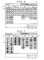
- a preceding information button 8e a following information button 8f, the top button 8g, and the button 8k for all-groups setting in a batch are displayed in the lower part of the controller display subunit 2d, as shown in Fig. 6 .
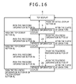
- display is sequentially switched from [the detailed information 1 display screen 9 ⁇ the detailed information 2 display screen 10 ⁇ ... ⁇ the detailed information n display screen 20 ⁇ the top screen 8] at the time of every push of the following information button 8f, as shown in a flow chart of Fig. 16 .
- the top button 8g is provided, it is possible to cause any detailed information display screen to revert to the top screen 8.
- the detailed information 1 display screen 9 is similarly the operation-mode display screen shown in Fig. 4 .
- the immediately following detailed information screen is displayed (if the immediately following screen is the top screen, the top screen is displayed) and a push of the preceding information button 8e, an immediately preceding detailed-information screen is displayed.
- the operation-mode display screen 9 is caused to revert to the top screen. More specifically, as shown in the flow chart of Fig. 16 , with a push of the detail-display button 8d in the top screen 8 shown in Fig.
- a configuration may be adopted such that if a button manipulation is not executed for a given time period after switching of the detailed information display screen, the screen is caused to automatically revert to the top screen 8.
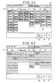
- the detailed information display screen is shifted to a fan speed display screen 11 shown in Fig. 6 , and further, at the time of every push of the detail-display button 8d or the following information button 8f, the fan speed display screen 11 is sequentially switched to a wind-direction display screen 12 shown in Fig. 7 , a maintenance-information display screen 14 shown in Fig. 10 , a compressor operation-state display screen 15 shown in Fig. 11 , and an air-conditioner accumulated operation-time display screen 16 shown in Fig. 12 .
- the detailed information display screen can be sequentially shifted to the following screens to thereby cause operation-information on all the air-conditioner groups to be displayed on one screen, so that it is possible to keep displaying any number of operation-information pieces that need be displayed.
- the respective icons of all the groups are displayed in a batch (the respective icons of all the groups are displayed on one screen) , and the icons of the respective groups are displayed at respective positions identical to each other, in the controller display subunit 2d, so that even if the screen is shifted to any of the detailed information screens, it is possible to instantly ascertain the operation-information on the air-conditioner group to be ascertained.
- the respective group icons 8a are displayed in colors differing from each other by the operation mode of each of the air-conditioner groups (with the present embodiment, the colors differing from each other are expressed by indicating the respective group icons 8a that are shown in differently textured half-tone dot meshing), as shown in Fig. 4 .
- divergent operation modes an operation mode as set from the centralized controller 2 differing from an operation mode actually in operation due to an operation cycle state of the outdoor unit 3
- both the operation modes are displayed.
- a divergent operation modes group icon 9a As shown by a divergent operation modes group icon 9a, "heating” according to an operation mode (the divergent operation modes) set from the centralized controller 2 is displayed in upper steps, and “cooling” according to the operation mode (a real operation mode) of the outdoor unit 3 actually in operation is displayed in lower steps by flashing light.
- the set-temperatures of the respective air-conditioner groups are displayed on the set-temperature display screen 10, as shown in Fig. 5 .
- a recommendable temperature can be preset, and it can be ascertained on the set-temperature display screen 10 that a set-temperature for the duration of a cooling operation is set lower than a recommendable cooling temperature or a set-temperature for the duration of a heating operation is set higher than a recommendable heating temperature.
- the recommendable cooling temperature and the recommendable heating temperature can be set on common screens as integrated after transition to a recommendable temperature setting screen 17 shown in Fig. 13 from the menu button 8j on the top screen 8 shown in Fig. 3 .
- a recommendable cooling temperature 28°C in this example
- the group icon 8a of the air-conditioner group is displayed in a color different from a normal color.
- the set-temperatures of an air-conditioner group, set lower than the recommendable cooling temperature are forcefully changed to the recommendable cooling temperature (28°C) in a batch, whereupon the group icon 8a of the air-conditioner group whose set-temperature has been changed to the recommendable cooling temperature is displayed in the normal color.
- a recommendable heating temperature setting button 8i on the screen of Fig.
- the set-temperatures of an air-conditioner group are forcefully changed to the recommendable heating temperature (20°C) in a batch, whereupon the group icon 8a of the air-conditioner group whose set-temperature has been changed to the recommendable heating temperature is displayed in the normal color.
- the group icon 8a is displayed in the color different from the normal color for the purpose of warning, however, the group icon 8a may be, for example, flashed instead of varying color for the purpose of warning to be thereby displayed.
- the air-conditioner group that is forcefully changed in a batch by the recommendable cooling temperature setting button 8h or the recommendable heating temperature setting button 8i, and an air-conditioner group other than a target for a change in a batch are preset, this will enable flexible support matching the actual state of an area as a target for air-conditioning management.
- a flow chart of a display method described in Fig. 5 is as shown in Fig. 17 . More specifically, if the recommendable cooling temperature is set by the centralized controller 2 shown in Figs. 1, and 2 , respectively, the set-temperature of a group is set lower than the recommendable cooling temperature, and the group icon 8a of the group as the target for the change in a batch is displayed in the color different from the normal color.
- the recommendable cooling temperature setting button 8h shown in Fig. 5 being pushed in this state, the set-temperatures of all the groups as the targets for the change in a batch are forcefully changed to the recommendable cooling temperature, and the group icon 8a is displayed in the normal color, as shown in Fig. 17 (a) .
- the recommendable heating temperature is set by the centralized controller 2 shown in Figs. 1, and 2 , respectively, the set-temperature of a group is set higher than the recommendable heating temperature, and the group icon 8a of the group as the target for the change in a batch is displayed in the color other than the normal color, and the color in the case where the set-temperature is lower than the recommendable cooling temperature.
- the recommendable heating temperature setting button 8i shown in Fig. 5 being pushed in this state, the set-temperatures of all the groups as the targets for the change in a batch are forcefully changed to the recommendable heating temperature, and the group icon 8a is displayed in the normal color, as shown in Fig. 17 (b) .
- the set-temperature can be switched over in display between Celsius temperature and Fahrenheit temperature (not shown).
- the respective group icons 8a are displayed in colors differing from each other by the fan speed of each of the air-conditioner groups, as shown in Fig. 6 .
- the wind-direction angle can be set in 8 stages, and displays in the controller display subunit 2d are provided according to respective wind-directions that are set, as shown in Fig. 8 . More specifically, the wind-direction in a first stage corresponds to an angle at which air is blew off in a direction closest to the horizontal direction, the wind-directions in second and third stages, respectively, gradually point more downward, and the wind-direction in a seventh stage corresponds to an angle at which the air is blew off in the most downward direction.
- an auto wind-direction mode which is a mode for causing the wind-direction to be automatically varied from the horizontal direction to downward or from downward to the horizontal direction.
- the respective group icons 8a of the air-conditioner groups with a fixed wind-direction angle are displayed in a color differing from a color in which the respective group icons 8a of the groups where the auto wind-direction mode is set.
- an outdoor unit operation cycle display screen (not shown) for displaying the operation cycle state of the outdoor unit 3, and the operation modes (a cooling-operation mode, a heating-operation mode, an auto cooling/heating operation mode, a dry operation mode, and so forth) of the outdoor unit 3 are displayed on the outdoor unit operation cycle display screen.
- the operation-mode display screen 9 shown in Fig. 4 the respective group icons 8a are displayed in colors differing from each other by the operation mode.
- an operation-condition setting screen 13 shown in Fig. 9 is displayed in a pop-up fashion.
- setting of run/stop setting of an operation mode, setting of a set-temperature, setting of an fan speed, setting of wind-direction, setting of remote control operation (permitted/prohibition), and a change in the contents of setting can be executed from the operation-condition setting screen 13.
- the various-information icons 8c applicable to those information, respectively are displayed in the respective group icons 8a, as shown in the figure.
- the respective group icons 8a are displayed in various colors different from the normal color.
- thermometer display screen Besides the display screens described as above, there are provided detailed information screens including an inlet-temperature display screen, an ambient-temperature display screen, a remote control thermometer display screen, a remote thermometer display screen, and so forth, and respective temperatures are displayed as is the case with the set-temperature display screen 10 shown in Fig. 5 . Temperature in the periphery of a remote control switch is displayed on the remote control thermometer display screen, and a mean value between the inlet-temperature and the reading of a remote thermometer is displayed on the remote thermometer display screen
- accumulated operation time of the indoor unit 4 of the relevant air-conditioner group in, for example, a relevant month, is displayed as "such and such hours” or "such and such h” or “such and such H”.
- guidance operation hours in this example, 600 hours
- the group icon 8a of the relevant air-conditioner group is displayed in a color different from the normal color.
- thermo-ON time display screen (not shown)
- compressor operation hours of the air-conditioner group connected to the outdoor unit, in the relevant month are displayed as is the case with the air-conditioner accumulated operation-time display screen 16 shown in Fig. 12 .
- Fig. 13 shows the screen 17 for setting the recommendable cooling temperature, and the recommendable heating temperature, and a transition from the menu button 8j shown in Fig. 3 to the screen 17 is possible, thereby enabling the recommendable cooling temperature, and the recommendable heating temperature for all the air-conditioner groups to be set in a batch.
- the present embodiment is configured such that display items can be preset as appropriate so as to enable only necessary information according to an operator (a supervisor, service man, and so forth), operating the centralized controller 2, to be displayed on the detailed information display setting screen 18. More specifically, setting can be executed whereby detailed information 1, and detailed information 2 are displayed in "display mode 1" while detailed information 3 is displayed in "display mode 2" on the detailed information display setting screen 18.
- the display mode 1 is used as a monitoring mode to display the operation-mode, and the set-temperature while the display mode 2 is used as an inspection mode to display the inlet-temperature, and the remote control thermometer.
- a flow chart of this operation is as shown in Fig. 18 .
- Display or non-display with respect to the respective detailed information pieces 1, 2, ... is decided upon, and setting is made on whether detailed information to be displayed is displayed in the display mode 1, in the display mode 2, or in both the display mode 1 and the display mode 2. If the setting is made as above, the detailed information screens that are set so as to be displayed in the display mode 1 are sequentially displayed in the display mode 1 while the detailed information screens that are set so as to be displayed in the display mode 2 are sequentially displayed in the display mode 2, so that only necessary items according to the operator operating the centralized controller 2 can be sequentially displayed, thereby enabling the operator to reach the target information in short time.
- setting can also be made such that, for example, if the detail-display button 8d is pushed once on the screen of Fig. 3 , the display mode 1 will occur, and if the detail-display button 8d is pushed for awhile, the display mode 2 will occur.
- the respective group icons 8a showing information on the air-conditioner group in whole are displayed at a given layout on one screen instead of displaying a wide variety of the detailed information (ascertainment of the operation-information such as the operation mode by the air-conditioner group, the set-temperature, and so forth, ascertainment of maintenance-information such as necessity/non-necessity of inspection, necessity/non-necessity of filter-cleaning, and so forth ) in one batch on the screen of the centralized controller 2 for managing the plural air conditioners, and the detailed information is switched to be displayed every time the button is pushed once while displaying the respective group icons 8a showing the operation-information on the air-conditioner group in whole at the given layout by one variety after another on one screen, so that different detailed information pieces can be sequentially displayed at respective positions identical to each other, thereby enabling an air-conditioning management system capable of easily ascertaining the respective varieties of the detailed information pieces on the air-conditioner group in whole to
- the present embodiment has an effect that a setting-change can be instantly executed by a simple operation after ascertaining the operation state. Further, since the respective varieties of the detailed information pieces are switched by one variety after another to be then displayed, the present embodiment has another effect that characters and figures, large in size, can be displayed.
- a maintenance icon for "emergency stop, " "inspection required, " "filter cleaning required,” and so forth, as the various-information icon 8c, is also displayed in the upper part of the controller display subunit 2d, so that it is possible to instantly find out which air-conditioner group requires maintenance if the top screen 8 is caused to undergo a transition to the maintenance-information display screen 14 shown in Fig. 10 . Accordingly, the present embodiment has still another effect that hinders overlooking of maintenance-information can be prevented, and speedy maintenance can be performed.
- the present embodiment Since respective temperatures set on an group-by-group basis can be instantly found out from the set-temperature display screen 10, the present embodiment has a further effect in that over-cooling and over-heating are prevented, and the centralized controller 2 can forcefully changes the set-temperature, thereby reducing energy consumption. Furthermore, not only general users such as a building supervisor and so forth can easily find out necessary operation-information but also a service worker responsible for maintenance of the air-conditioners can easily find out operation-information necessary at the time of an inspection.
- the present embodiment it is possible to display the respective varieties of the detailed information pieces on the plural air-conditioner groups on the display subunit of the centralized controller in such a way as to enable an operator to easily ascertain the information pieces by a simple operation, so that it is possible to obtain an air-conditioning management system capable of easily getting hold of an air-conditioner group deviating from the setting of the air-conditioning management system, thereby instantly executing a setting-change.
Landscapes
- Engineering & Computer Science (AREA)
- Chemical & Material Sciences (AREA)
- Combustion & Propulsion (AREA)
- Mechanical Engineering (AREA)
- General Engineering & Computer Science (AREA)
- Human Computer Interaction (AREA)
- Air Conditioning Control Device (AREA)
Abstract
Description
- The invention relates to an air-conditioning management system for managing a plurality of air conditioners, and in particular, to an air-conditioning management system for displaying information on a plurality of air conditioner groups in a batch.
- An air-conditioning management system is provided with a centralized controller for managing a plurality of air conditioners, and the centralized controller executes display and setting of respective operation states of air-conditioner groups. More specifically, the plural air conditioners are handled as an air-conditioner group (hereinafter also referred to simply as "a group") on a room-by-room basis, on a floor-by-floor-basis, and so forth to be thereby controlled.
- Air-conditioning management systems according to the related art include one described in
Patent Document 1. -
- Patent Document 1: Japanese Unexamined Patent Application Publication No.
2009-36392 - With the centralized controller of the air-conditioning management system according to the related art, an operation state, and operation data are displayed on a group-by-group basis to be thereby ascertained. However, this system is for displaying groups on a list, and displaying many information pieces, such as set-temperature, filter-cleaning required, and so forth, after integration on a group-by-group basis at a time. The system, therefore, has a problem in that it is not easy to ascertain information as needed. Further, it is necessary to execute several complex operations in order to cause the information as needed to be displayed.
- It is therefore an object of the invention to obtain an air-conditioning management system capable of causing information on various types of operations with respect to plural air-conditioner groups to be displayed on a group-by-group basis on the display subunit of a centralized controller in such a way as to be easily ascertained by a simple operation.
- To that end, in accordance with one aspect of the invention, there is provided an air-conditioning management system provided with a centralized controller for monitoring and controlling a plurality of air conditioner groups, the centralized controller comprising a controller display subunit, a group display means for displaying respective group display sites corresponding to the plural air conditioner groups on one screen of the controller display subunit in a batch, a group operation-information display means for displaying respective operation-information pieces of the plural air conditioner groups on the tone screen of the controller display subunit, and a display-contents switching means for switching the contents of display, displayed on the controller display subunit.
- Further, in accordance with one aspect of the invention, there is provided an air-conditioning management system provided with a centralized controller for monitoring and controlling a plurality of air conditioner groups by handling plural air conditioners as a group on a room-by-room basis, on a floor-by-floor-basis, and so forth, the centralized controller comprising a controller display subunit, wherein respective group icons corresponding to the plural air conditioner groups are displayed on one screen of the controller display subunit in a batch, and respective operation-information pieces of the plural air conditioner groups are displayed at respective sites of the group icons displayed on the one screen of the controller display subunit in a batch, the controller display subunit comprising a display-contents switching button for sequentially displaying the respective operation-information pieces of the plural air conditioner groups at the respective sites of the group icons displayed on the one screen of the controller display subunit in a batch.
- With the present invention, it is possible to obtain an air-conditioning management system capable of causing information pieces of plural air-conditioner groups to be displayed on a group-by-group basis on the display subunit of a centralized controller in such a way as to be easily ascertained by a simple operation.
-
-
Fig. 1 is a view showing an overall configuration of a first embodiment of an air-conditioning management system according to the invention; -
Fig. 2 is a control block diagram of the air-conditioning management system according to the first embodiment; -
Fig. 3 is a view showing an example of a top screen that is normally displayed on a display subunit of a centralized controller; -
Fig. 4 is a view showing an example of an operation-mode display screen; -
Fig. 5 is a view showing an example of a set-temperature display screen; -
Fig. 6 is a view showing an example of a fan speed display screen; -
Fig. 7 is a view showing an example of a wind-direction display screen; -
Fig. 8 is view for describing setting of wind-directions; -
Fig. 9 is a view showing an operation-detail setting screen in a pop-up fashion; -
Fig. 10 is a view showing an example of a maintenance-information display screen; -
Fig. 11 is a view showing an example of a compressor operation-state display screen; -
Fig. 12 is a view showing an example of an air-conditioner operation-time display screen; -
Fig. 13 is a view showing an example of a screen for setting a recommendable cooling temperature and a recommendable heating temperature; -
Fig. 14 is a view showing an example of a screen for setting detailed information displayed in units of display modes; -
Fig. 15 is a flow chart for describing switching of detailed information display to a display subunit; -
Fig. 16 is a flow chart for describing another example of switching of the detailed information display to the display subunit; -
Fig. 17 is a flow chart for describing the respective displays of group icons on the set-temperature display screen shown inFig. 5 in the case where a set-temperature set in a group differs from the recommendable cooling temperature or the recommendable heating temperature, preset by a centralized controller; and -
Fig. 18 is a flow chart for describing setting of detailed information to be displayed in units of display modes. - There are described hereinafter embodiments of the invention with reference to the accompanying drawings.
- A first embodiment of an air-conditioning management system according to the invention is described with reference to
Figs. 1, and 2. Fig. 1 is a view showing an overall configuration of the air-conditioning management system, and the air-conditioning management system 1 is provided with acentralized controller 2 for managing a plurality of air conditioners. The centralized controller executes display and setting of respective operation states of air-conditioner groups A1, A2, ... (inFig. 1 , only A1, A2 are shown; however, the number of the groups may be not less than three). More specifically, plural indoor units 4 (4,..., 4n) are handled as a group A1, A2,... on a room-by-room basis, on a floor-by-floor-basis, and so forth to be thereby controlled. The respective air-conditioner groups are made up such that the plural indoor units 4 (4, ..., 4n) connected to, for example, one remote-control switch 5 are integrated with each other, and monitoring and controlling of the pluralindoor units 4 can be executed in a batch. - Further, a plurality of the groups A1, A2,... integrated with each other, are handled as an air conditioner block (hereinafter referred to as a block) . In
Fig 1 , only the block A is shown, however, not less than two blocks (the blocks B, C, D,...) can be connected to one controller, that is, thecentralized controller 2. - Plural
outdoor units 3, the pluralindoor units 4, aregeneration unit 7, the remote-control switch (hereinafter referred to simply as "remote control") 5, and so forth are connected to thecentralized controller 2 via acontrol wiring 6. -
Fig. 2 is a control block diagram of the air-conditioning management system according to the present embodiment. Thecentralized controller 2 includes acommunication subunit 2a, acontrol subunit 2b, aninput subunit 2c, acontroller display subunit 2d, and astorage subunit 2e. Theindoor unit 4 is provided with acontrol subunit 4b, and acommunication subunit 4a for use in communication with thecentralized controller 2, theoutdoor unit 3, and theremote control 5, respectively. Theoutdoor unit 3 is provided with a communication subunit 3a for use in communication with thecommunication subunit 4a, and acontrol subunit 3b. Theremote control 5 is provided with not only acommunication subunit 5a for use in communication with thecommunication subunit 4a, but also acontrol subunit 5b, aninput subunit 5c, adisplay subunit 5d, and astorage subunit 5e. - The
control subunit 2b of thecentralized controller 2 transmits an operation-instruction demand (change in operation mode, set temperature, and so forth) from theinput subunit 2c to theindoor unit 4 via thecontrol wiring 6 from thecommunication subunit 2a. The operation-instruction demand is received by thecommunication subunit 4a, whereupon the operation-instruction demand is executed by thecontrol subunit 4b. After the execution, thecontrol subunit 4b of the indoor unit transmits changed data to thecentralized controller 2 via thecommunication subunit 4a, and thecontrol wiring 6. Thecommunication subunit 2a of the centralizedcontroller 2 receives the changed data from thecommunication subunit 4a of the indoor unit, thereby displaying the contents of a change on thecontroller display subunit 2d. Further, the changed data is also transmitted from thecommunication subunit 4a of the indoor unit to theoutdoor unit 3, and theremote control 5, respectively. - Transmission of an operation-instruction demand from the
remote control 5 as well can be made to theindoor unit 4, and this operation-instruction demand from theremote control 5 is transmitted to thecommunication subunit 4a of theindoor unit 4 via thecommunication subunit 5a of the remote control, and thecontrol wiring 6. In the case of the operation-instruction demand received from theremote control 5, changed data is also transmitted to the centralizedcontroller 2, and theoutdoor unit 3 via thecommunication subunit 4a of theindoor unit 4, and thecontrol wiring 6. - Further, communication is performed between the
indoor unit 4 and thecentralized controller 2 every time operation data is changed, or at a given time interval, and thecentralized controller 2 retains information on an operation between theoutdoor unit 3 having received the operation data from theindoor unit 4, and theindoor unit 4, and so forth in thestorage subunit 2e. By so doing, information (operation-information, group name, and so forth) on the respective air-conditioner groups A1, A2, ... can be displayed on thecontroller display subunit 2d to be thereby ascertained. - Next, there is described hereinafter an example of display at the
controller display subunit 2d according to the present embodiment with reference toFigs. 3 - Figs. 18 .
Fig. 3 shows a top screen that is normally displayed by thecentralized controller 2. In thefigure, 8a denotes a group icon corresponding to an individual air-conditioner group, and 8b denotes a block icon corresponding to individual air conditioner block categorized by the plural air-conditioner groups. The name of the individual air-conditioner group is displayed in the group icon, and the name of the individual air conditioner block is displayed in the block icon. - In the case of this example, four blocks including A block (1F Center), B block (1F Conference Room), C block (1 F Office) and D block (2 F Tenant) are displayed in the
block icon 8b. The respective blocks include at least one group of the air-conditioner group, and therespective group icons 8a of the air-conditioner groups included in each of the blocks are displayed under each of the block icons. More specifically, the icons such as the group icons A1 (the air-conditioner group for air-conditioning of the general affairs dept.), A2 (the air-conditioner group for air-conditioning of the accounting business dept. ) , ... and so forth are disposed under the block icon A for the purpose of display. - Similarly, the group icons B1 (the air-conditioner group for air-conditioning of Conference Room 1), B2 (the air-conditioner group for air-conditioning of Conference Room 2), ..., and so forth are disposed under the block icon B, the group icons C1 (the air-conditioner group for air-conditioning of Office 1), C2 (the air-conditioner group for air-conditioning of Office 2), ..., and so forth are disposed under the block icon C, and the group icons D1 (the air-conditioner group for air-conditioning of
Tenant 1A), D2 (the air-conditioner group for air-conditioning ofTenant 1B), ..., and so forth are disposed under the block icon D, respectively. - The
respective group icons 8a are made up so as to be displayed in respective colors different from each other for every run/stop. - In the case where there exists not less than one group of the groups including at least one indoor unit 3 (4) where "regeneration operation," "inspection required," "operation under restriction," "filter cleaning required," "timer setting," and so forth are applicable, or at least one
regeneration unit 7, or all theindoor units 4 connected to thecentralized controller 2 are under setting of "remote control operation prohibited," a various-information icon 8c is displayed in the upper part of thecontroller display subunit 2d. Date and time are also displayed in the upper part of thecontroller display subunit 2d. - Further, a detail-
display button 8d, amenu button 8j, abutton 8k for all-groups setting in a batch, abutton 81 for all-groups operation in a batch, and abutton 8m for all the-groups stop in a batch are displayed in the lower part of thecontroller display subunit 2d. - With a push of the detail-
display button 8d, thetop screen 8 is switched to adetailed information 1display screen 9. There are available two different methods for switching between detailed information display screens thereafter. - With one of the methods, after the information display screen is switched to the
detailed information 1display screen 9, the detail-display button 8d, atop button 8g, and thebutton 8k for all-groups setting in a batch are displayed in the lower part of thecontroller display subunit 2d, as shown inFig. 4 . As shown in a flow chart ofFig. 15 , display is sequentially switched from [thedetailed information 1display screen 9 → adetailed information 2display screen 10 → ... → a detailed informationn display screen 20 → the top screen 8] at the time of every push of the detail-display button 8d. As thetop button 8g is provided, it is possible to cause any detail-display screen to revert to thetop screen 8. - With the present embodiment, the
detailed information 1display screen 9 is an operation-mode display screen shown inFig. 4 . With a push of the detail-display button 8d in this operation-mode display screen 9, an immediately following detailed information screen is displayed (if the immediately following screen is the top screen, the top screen is displayed) . Further, with a push of thetop button 8g, the operation-mode display screen 9 is caused to revert to the top screen. More specifically, as shown in the flow chart ofFig. 15 , with the push of thetop button 8d on thetop screen 8 shown inFig. 3 , there occurs a transition to thedetailed information 1 display screen 9 (the operation-mode display screen), and with a push of the detail-display button 8d again, thedetailed information 1display screen 9 is switched to an immediately successivedetailed information 2 display screen 10 (in this example, to a set-temperature display screen shown inFig. 5 ) . Thereafter, at the time of every push of the detail-display button 8d, a detailed information display screen undergoes a transition to the next detailed information display screen, and with a push of the detail-display button 8d in the detailed informationn display screen 20, the detailed informationn display screen 20 is caused to revert to thetop screen 8. Further, with the push of the detail-display button 8d in any of the detailed information display screen, any detailed information display screen can be reverted to thetop screen 8. - With another of the methods, after the information display screen is switched to the
detailed information 1display screen 9, a precedinginformation button 8e, a followinginformation button 8f, thetop button 8g, and thebutton 8k for all-groups setting in a batch are displayed in the lower part of thecontroller display subunit 2d, as shown inFig. 6 . By so doing, display is sequentially switched from [thedetailed information 1display screen 9 → thedetailed information 2display screen 10 → ... → the detailed informationn display screen 20 → the top screen 8] at the time of every push of the followinginformation button 8f, as shown in a flow chart ofFig. 16 . Further, since thetop button 8g is provided, it is possible to cause any detailed information display screen to revert to thetop screen 8. - With this example as well, the
detailed information 1display screen 9 is similarly the operation-mode display screen shown inFig. 4 . With a push of the followinginformation button 8f in this operation-mode display screen 9, the immediately following detailed information screen is displayed (if the immediately following screen is the top screen, the top screen is displayed) and a push of the precedinginformation button 8e, an immediately preceding detailed-information screen is displayed. Further, with the push of thetop button 8g, the operation-mode display screen 9 is caused to revert to the top screen. More specifically, as shown in the flow chart ofFig. 16 , with a push of the detail-display button 8d in thetop screen 8 shown inFig. 3 , there occurs a transition to thedetailed information 1 display screen 9 (the operation-mode display screen), and subsequently, with a push of the followinginformation button 8f, thedetailed information 1display screen 9 is switched to an immediately followingdetailed information 2 display screen 10 (the set-temperature display screen shown inFig. 5 ) . Thereafter, at the time of every push of the followinginformation button 8f, thedetailed information 2display screen 10 undergoes a transition to the next detailed information display screen, and with a push of the followinginformation button 8f in the detailed informationn display screen 20, the detailed informationn display screen 20 is caused to revert to thetop screen 8. Further, with a push of the precedinginformation button 8e, an immediately preceding detailed information screen can be displayed. Further, with the push of the precedinginformation button 8e in any of the detailed information display screen, any detailed information display screen can be reverted to thetop screen 8. - Further, a configuration may be adopted such that if a button manipulation is not executed for a given time period after switching of the detailed information display screen, the screen is caused to automatically revert to the
top screen 8. - With the present embodiment, with a push of the detail-
display button 8d or the followinginformation button 8f in thedetailed information 2 display screen 10 (the set-temperature display screen shown inFig. 5 ), the detailed information display screen is shifted to a fanspeed display screen 11 shown inFig. 6 , and further, at the time of every push of the detail-display button 8d or the followinginformation button 8f, the fanspeed display screen 11 is sequentially switched to a wind-direction display screen 12 shown inFig. 7 , a maintenance-information display screen 14 shown inFig. 10 , a compressor operation-state display screen 15 shown inFig. 11 , and an air-conditioner accumulated operation-time display screen 16 shown inFig. 12 . Thus, with the present embodiment, at the time of every push of the detail-display button 8d or the followinginformation button 8f, the detailed information display screen can be sequentially shifted to the following screens to thereby cause operation-information on all the air-conditioner groups to be displayed on one screen, so that it is possible to keep displaying any number of operation-information pieces that need be displayed. Furthermore, the respective icons of all the groups are displayed in a batch (the respective icons of all the groups are displayed on one screen) , and the icons of the respective groups are displayed at respective positions identical to each other, in thecontroller display subunit 2d, so that even if the screen is shifted to any of the detailed information screens, it is possible to instantly ascertain the operation-information on the air-conditioner group to be ascertained. - Next, there is described the contents of display on each of the detailed information display screens.
In the operation-mode display screen 9, therespective group icons 8a are displayed in colors differing from each other by the operation mode of each of the air-conditioner groups (with the present embodiment, the colors differing from each other are expressed by indicating therespective group icons 8a that are shown in differently textured half-tone dot meshing), as shown inFig. 4 . In the case of divergent operation modes (an operation mode as set from thecentralized controller 2 differing from an operation mode actually in operation due to an operation cycle state of the outdoor unit 3) , both the operation modes are displayed. As shown by a divergent operation modes group icon 9a, "heating" according to an operation mode (the divergent operation modes) set from thecentralized controller 2 is displayed in upper steps, and "cooling" according to the operation mode (a real operation mode) of theoutdoor unit 3 actually in operation is displayed in lower steps by flashing light. - The set-temperatures of the respective air-conditioner groups are displayed on the set-
temperature display screen 10, as shown inFig. 5 . A recommendable temperature can be preset, and it can be ascertained on the set-temperature display screen 10 that a set-temperature for the duration of a cooling operation is set lower than a recommendable cooling temperature or a set-temperature for the duration of a heating operation is set higher than a recommendable heating temperature. The recommendable cooling temperature and the recommendable heating temperature can be set on common screens as integrated after transition to a recommendabletemperature setting screen 17 shown inFig. 13 from themenu button 8j on thetop screen 8 shown inFig. 3 . - In
Fig. 5 , if the set-temperature of an air-conditioner group for the duration of the cooling operation is set lower than a recommendable cooling temperature (28°C in this example), thegroup icon 8a of the air-conditioner group is displayed in a color different from a normal color. With a push of a recommendable coolingtemperature setting button 8h on the screen ofFig. 5 , the set-temperatures of an air-conditioner group, set lower than the recommendable cooling temperature, are forcefully changed to the recommendable cooling temperature (28°C) in a batch, whereupon thegroup icon 8a of the air-conditioner group whose set-temperature has been changed to the recommendable cooling temperature is displayed in the normal color. - Similarly, in
Fig. 5 , if the set-temperature of an air-conditioner group for the duration of the heating operation is higher than a recommendable heating temperature (20°C in this example), thegroup icon 8a of the air-conditioner group is displayed in a color other than the normal color, and the color in the case where the set-temperature is lower than the recommendable cooling temperature.
With a push of a recommendable heatingtemperature setting button 8i on the screen ofFig. 5 , the set-temperatures of an air-conditioner group, set higher than the recommendable heating temperature, are forcefully changed to the recommendable heating temperature (20°C) in a batch, whereupon thegroup icon 8a of the air-conditioner group whose set-temperature has been changed to the recommendable heating temperature is displayed in the normal color. - With this example, if the set-temperature for the duration of the cooling operation is lower than the recommendable cooling temperature or the set-temperature for the duration of the heating operation is higher than the recommendable heating temperature, the
group icon 8a is displayed in the color different from the normal color for the purpose of warning, however, thegroup icon 8a may be, for example, flashed instead of varying color for the purpose of warning to be thereby displayed. - Further, if the air-conditioner group that is forcefully changed in a batch by the recommendable cooling
temperature setting button 8h or the recommendable heatingtemperature setting button 8i, and an air-conditioner group other than a target for a change in a batch are preset, this will enable flexible support matching the actual state of an area as a target for air-conditioning management. - A flow chart of a display method described in
Fig. 5 is as shown inFig. 17 . More specifically, if the recommendable cooling temperature is set by thecentralized controller 2 shown inFigs. 1, and 2 , respectively, the set-temperature of a group is set lower than the recommendable cooling temperature, and thegroup icon 8a of the group as the target for the change in a batch is displayed in the color different from the normal color. Upon the recommendable coolingtemperature setting button 8h shown inFig. 5 being pushed in this state, the set-temperatures of all the groups as the targets for the change in a batch are forcefully changed to the recommendable cooling temperature, and thegroup icon 8a is displayed in the normal color, as shown inFig. 17 (a) . Similarly, if the recommendable heating temperature is set by thecentralized controller 2 shown inFigs. 1, and 2 , respectively, the set-temperature of a group is set higher than the recommendable heating temperature, and thegroup icon 8a of the group as the target for the change in a batch is displayed in the color other than the normal color, and the color in the case where the set-temperature is lower than the recommendable cooling temperature. Upon the recommendable heatingtemperature setting button 8i shown inFig. 5 being pushed in this state, the set-temperatures of all the groups as the targets for the change in a batch are forcefully changed to the recommendable heating temperature, and thegroup icon 8a is displayed in the normal color, as shown inFig. 17 (b) . The set-temperature can be switched over in display between Celsius temperature and Fahrenheit temperature (not shown). - With the fan
speed display screen 11, therespective group icons 8a are displayed in colors differing from each other by the fan speed of each of the air-conditioner groups, as shown inFig. 6 . - On the wind-
direction display screen 12 shown inFig. 7 , there is displayed a wind-direction angle of a blow-off air blew off from theindoor unit 4. With the present embodiment, the wind-direction angle can be set in 8 stages, and displays in thecontroller display subunit 2d are provided according to respective wind-directions that are set, as shown inFig. 8 . More specifically, the wind-direction in a first stage corresponds to an angle at which air is blew off in a direction closest to the horizontal direction, the wind-directions in second and third stages, respectively, gradually point more downward, and the wind-direction in a seventh stage corresponds to an angle at which the air is blew off in the most downward direction. Further, there is provided an auto wind-direction mode, which is a mode for causing the wind-direction to be automatically varied from the horizontal direction to downward or from downward to the horizontal direction. As shown inFig. 7 , therespective group icons 8a of the air-conditioner groups with a fixed wind-direction angle are displayed in a color differing from a color in which therespective group icons 8a of the groups where the auto wind-direction mode is set. - There is also provided an outdoor unit operation cycle display screen (not shown) for displaying the operation cycle state of the
outdoor unit 3, and the operation modes (a cooling-operation mode, a heating-operation mode, an auto cooling/heating operation mode, a dry operation mode, and so forth) of theoutdoor unit 3 are displayed on the outdoor unit operation cycle display screen. As is the case with the operation-mode display screen 9 shown inFig. 4 , therespective group icons 8a are displayed in colors differing from each other by the operation mode. - Upon the
group icon 8a of an air-conditioner group, theblock icon 8b, or thebutton 8k for all-groups setting in a batch being pushed on the operation-mode display screen 9 (Fig. 4 ), the set-temperature display screen 10 (Fig. 5 ), the fan speed display screen 11 (Fig. 6 ), the wind-direction display screen 12 (Fig. 7 ), and the outdoor unit operation cycle display screen (not shown), respectively, an operation-condition setting screen 13 shown inFig. 9 is displayed in a pop-up fashion. With respect to a relevant air-conditioner group, block, or all the air-conditioner groups, setting of run/stop, setting of an operation mode, setting of a set-temperature, setting of an fan speed, setting of wind-direction, setting of remote control operation (permitted/prohibition), and a change in the contents of setting can be executed from the operation-condition setting screen 13. - If the respective air-conditioner groups apply to at least any of "regeneration operation," "inspection required," "operation under restriction (demand setting)," "filter cleaning required," "timer setting," and "remote control operation prohibited" on the maintenance-
information display screen 14 shown inFig. 10 , the various-information icons 8c applicable to those information, respectively, are displayed in therespective group icons 8a, as shown in the figure. In such a case, therespective group icons 8a are displayed in various colors different from the normal color. - Besides the display screens described as above, there are provided detailed information screens including an inlet-temperature display screen, an ambient-temperature display screen, a remote control thermometer display screen, a remote thermometer display screen, and so forth, and respective temperatures are displayed as is the case with the set-
temperature display screen 10 shown inFig. 5 . Temperature in the periphery of a remote control switch is displayed on the remote control thermometer display screen, and a mean value between the inlet-temperature and the reading of a remote thermometer is displayed on the remote thermometer display screen - In the case of the compressor operation-
state display screen 15 shown inFig. 11 , if a compressor of the outdoor unit to which a relevant air-conditioner group is connected via piping is in operation, "thermo ON" is displayed, and if the compressor is in stop, "thermo OFF" is displayed. In the case of "thermo ON,"relevant group icons 8a are displayed in a color different from the normal color. - In the case of the air-conditioner operation-
time display screen 16 shown inFig. 12 , accumulated operation time of theindoor unit 4 of the relevant air-conditioner group, in, for example, a relevant month, is displayed as "such and such hours" or "such and such h" or "such and such H". InFig. 12 , guidance operation hours (in this example, 600 hours) can be preset, and if accumulated the operation time exceeds the guidance operation hours, thegroup icon 8a of the relevant air-conditioner group is displayed in a color different from the normal color. - In the case of the outdoor unit compressor's thermo-ON time display screen (not shown), compressor operation hours of the air-conditioner group connected to the outdoor unit, in the relevant month, are displayed as is the case with the air-conditioner accumulated operation-
time display screen 16 shown inFig. 12 . -
Fig. 13 shows thescreen 17 for setting the recommendable cooling temperature, and the recommendable heating temperature, and a transition from themenu button 8j shown inFig. 3 to thescreen 17 is possible, thereby enabling the recommendable cooling temperature, and the recommendable heating temperature for all the air-conditioner groups to be set in a batch. - Further, it is also possible to effect transition from the
menu button 8j shown inFig. 3 to a detailed informationdisplay setting screen 18 shown inFig. 14 . With respect to displays on the detailed informationdisplay setting screens 9 to 16, and so forth, respectively, a multitude of items of the displays can be set, so that if all the detailed information display setting screens are sequentially displayed at all times, it is expected to take much time before reaching target information. Accordingly, the present embodiment is configured such that display items can be preset as appropriate so as to enable only necessary information according to an operator (a supervisor, service man, and so forth), operating thecentralized controller 2, to be displayed on the detailed informationdisplay setting screen 18. More specifically, setting can be executed wherebydetailed information 1, anddetailed information 2 are displayed in "display mode 1" whiledetailed information 3 is displayed in "display mode 2" on the detailed informationdisplay setting screen 18. - For example, with respect to the operation-mode display screen 9 (
Fig. 4 ), and the set-temperature display screen 10 (Fig. 5 ) on the detailed informationdisplay setting screen 18 shown inFig. 14 , display in "display mode 1" is selected with a push of adisplay mode 1button 18a, while with respect to the inlet-temperature display screen, and the remote control thermometer display screen, display in "display mode 2" is selected with a push of adisplay mode 2button 18b. Thus, necessity/non-necessity of displaying respective detailed information pieces can be selected for every display mode. By so doing, the operation-mode display screen 9, and the set-temperature display screen 10 can be sequentially displayed in "display mode 1," and the inlet-temperature display screen, and the remote control thermometer display screen can be sequentially displayed in "display mode 2". - Accordingly, there is available an application method whereby the
display mode 1 is used as a monitoring mode to display the operation-mode, and the set-temperature while thedisplay mode 2 is used as an inspection mode to display the inlet-temperature, and the remote control thermometer. - A flow chart of this operation is as shown in
Fig. 18 . Display or non-display with respect to the respectivedetailed information pieces display mode 1, in thedisplay mode 2, or in both thedisplay mode 1 and thedisplay mode 2. If the setting is made as above, the detailed information screens that are set so as to be displayed in thedisplay mode 1 are sequentially displayed in thedisplay mode 1 while the detailed information screens that are set so as to be displayed in thedisplay mode 2 are sequentially displayed in thedisplay mode 2, so that only necessary items according to the operator operating thecentralized controller 2 can be sequentially displayed, thereby enabling the operator to reach the target information in short time. - Further, as to selection of the display mode, setting can also be made such that, for example, if the detail-
display button 8d is pushed once on the screen ofFig. 3 , thedisplay mode 1 will occur, and if the detail-display button 8d is pushed for awhile, thedisplay mode 2 will occur. - As described in the foregoing, with the present embodiment, the
respective group icons 8a showing information on the air-conditioner group in whole are displayed at a given layout on one screen instead of displaying a wide variety of the detailed information (ascertainment of the operation-information such as the operation mode by the air-conditioner group, the set-temperature, and so forth, ascertainment of maintenance-information such as necessity/non-necessity of inspection, necessity/non-necessity of filter-cleaning, and so forth ) in one batch on the screen of thecentralized controller 2 for managing the plural air conditioners, and the detailed information is switched to be displayed every time the button is pushed once while displaying therespective group icons 8a showing the operation-information on the air-conditioner group in whole at the given layout by one variety after another on one screen, so that different detailed information pieces can be sequentially displayed at respective positions identical to each other, thereby enabling an air-conditioning management system capable of easily ascertaining the respective varieties of the detailed information pieces on the air-conditioner group in whole to be implemented. - Further, after an operation state is displayed in the controller display subunit of the centralized controller, and the operation state is ascertained, it is possible to cause a setting-change screen to be displayed in the pop-up fashion as is the case with the operation-
condition setting screen 13, so that the present embodiment has an effect that a setting-change can be instantly executed by a simple operation after ascertaining the operation state.
Further, since the respective varieties of the detailed information pieces are switched by one variety after another to be then displayed, the present embodiment has another effect that characters and figures, large in size, can be displayed. - Further, if an equipment requiring maintenance is included in even one of the air-conditioner groups on the
top screen 8 shown inFig. 3 , a maintenance icon for "emergency stop, " "inspection required, " "filter cleaning required," and so forth, as the various-information icon 8c, is also displayed in the upper part of thecontroller display subunit 2d, so that it is possible to instantly find out which air-conditioner group requires maintenance if thetop screen 8 is caused to undergo a transition to the maintenance-information display screen 14 shown inFig. 10 . Accordingly, the present embodiment has still another effect that remiss overlooking of maintenance-information can be prevented, and speedy maintenance can be performed. - Since respective temperatures set on an group-by-group basis can be instantly found out from the set-
temperature display screen 10, the present embodiment has a further effect in that over-cooling and over-heating are prevented, and thecentralized controller 2 can forcefully changes the set-temperature, thereby reducing energy consumption. Furthermore, not only general users such as a building supervisor and so forth can easily find out necessary operation-information but also a service worker responsible for maintenance of the air-conditioners can easily find out operation-information necessary at the time of an inspection. - Thus, with the present embodiment, it is possible to display the respective varieties of the detailed information pieces on the plural air-conditioner groups on the display subunit of the centralized controller in such a way as to enable an operator to easily ascertain the information pieces by a simple operation, so that it is possible to obtain an air-conditioning management system capable of easily getting hold of an air-conditioner group deviating from the setting of the air-conditioning management system, thereby instantly executing a setting-change.
-
- 1: air-conditioning management system
- 2: centralized controller (2a: communication subunit, 2b:
control subunit - 3: outdoor unit (3a: communication subunit, 3b: control subunit)
- 4 (4,... 4n): indoor unit (4a: communication subunit, 4b: control subunit)
- 5: remote-control switch (remote control) (5a: communication subunit, 5b: control subunit, 5c; input subunit, 5d: display subunit, 5e: storage subunit)
- 6: control wiring
- 7: regeneration unit
- 8: top screen (8a: group icon (group display site), 8b: block icon, 8c: various-information icon, 8d: detail-display button (group operation-information display means), 8e: a preceding information button, 8f: a following information button, 8g: the top button:, 8h: recommendable cooling temperature setting button, 8i: recommendable heating temperature setting button, 8j: menu button, 8k: button for all-groups setting in a batch, 8l: button for all-groups operation in a batch, 8m: button for all the-groups stop in a batch)
- 9: operation-mode (detailed information 1) display screen (9a: divergent operation modes group icon)
- 10: set-temperature (detailed information 2) display screen
- 11: fan speed display screen
- 12: wind-direction display screen
- 13: operation-condition setting screen
- 14: maintenance-information display screen
- 15: compressor operation-state display screen
- 16: air-conditioner accumulated operation-time display screen
- 17: recommendable temperature setting screen
- 18: detailed information display setting screen (18a:
display mode 1 button, 18b:display mode 2 button) - 20: detailed information n display screen
- A, B, C, D: blocks
- A1, A2, B1, B2, C1, C 2: air-conditioner group (group)
Claims (14)
- An air-conditioning management system provided with a centralized controller for monitoring and controlling a plurality of air conditioner groups, the centralized controller comprising:a controller display subunit;a group display means for displaying respective group display sites corresponding to the plural air conditioner groups on one screen of the controller display subunit in a batch;a group operation-information display means for displaying respective operation-information pieces of the plural air conditioner groups on the tone screen of the controller display subunit, anda display-contents switching means for switching the contents of display, displayed on the controller display subunit.
- The air-conditioning management system according to claim 1, wherein the respective group display sites corresponding to the plural air conditioner groups are displayed on the one screen of the controller display subunit in a batch on a top screen normally displayed on the controller display subunit, and when the respective operation-information pieces of the plural air conditioner groups are displayed in a batch by the display-contents switching means, the respective operation-information pieces of the plural air conditioner groups, corresponding to the respective group display sites , are displayed at respective sites identical to each other.
- An air-conditioning management system provided with a centralized controller for monitoring and controlling a plurality of air conditioner groups by handling plural air conditioners as a group on each room, on each floor, and so forth, the centralized controller comprising:a controller display subunit, wherein respective group icons corresponding to the plural air conditioner groups are displayed on one screen of the controller display subunit in a batch, and respective operation-information pieces of the plural air conditioner groups are displayed at respective sites of the group icons displayed on the one screen of the controller display subunit in a batch, the controller display subunit comprising a display-contents switching button for sequentially displaying the respective operation-information pieces of the plural air conditioner groups at the respective sites of the group icons displayed on the one screen of the controller display subunit in a batch.
- The air-conditioning management system according to claim 1, wherein a screen for displaying the respective operation-information pieces of the plural air conditioner groups on the one screen of the controller display subunit in a batch is provided with a top button for causing the screen to be reverted to a top screen, and a button for causing the following operation-information to be displayed, or the top button for causing the screen to be reverted to the top screen, a button for displaying the following operation-information, and a button for causing the screen to reverted to an immediately preceding display screen.
- The air-conditioning management system according to claim 1, wherein display items in operation-information display of the air conditioner group can display at least not less than one item among "operation-mode display," "set-temperature display," "fan speed display," "wind-direction display," "outdoor unit operation cycle display," "regeneration operation display," "display for necessity/non-necessity of filter-cleaning," "operation under restriction," "display for filter cleaning required," "timer setting display," "display for remote control operation prohibited," "inlet-temperature display," "ambient-temperature display," "remote control thermometer display," "remote-thermometer display," "compressor operation-state display," "air-conditioner accumulated operation-time display," and "thermo-ON time display" with respect to the respective air conditioner groups.
- The air-conditioning management system according to claim 5, wherein at least not less than two items among the display items can be displayed, the centralized controller is provided with plural display modes, and not less than one item pre-selected from among the display items is displayed in the respective display modes.
- The air-conditioning management system according to claim 5, wherein at least "operation-mode display" is enabled from among the display items, and in response to operation modes of the respective air conditioner groups, display icons of the respective air conditioner groups are displayed in respective colors preset so as to corresponding to the operation modes.
- The air-conditioning management system according to claim 5, wherein the centralized controller is made up such that at least "set-temperature display" can be displayed from among the display items, and a recommendable cooling temperature as well as a recommendable heating temperature for the respective air conditioner groups can be set, and the air conditioner group as well is provided with a remote control, thereby causing the air conditioner group whose set-temperature is lower than the recommendable cooling temperature set by the centralized controller or the air conditioner group whose set-temperature is higher than the recommendable heating temperature to be in a alarm display differing from respective displays for other air conditioner groups on a screen for the set-temperature display.
- The air-conditioning management system according to claim 8, wherein temperature display according to plural systems, such as Celsius temperature, Fahrenheit temperature, and so forth, is enabled in the case of "set-temperature display" in the centralized controller.
- The air-conditioning management system according to claim 8, wherein the centralized controller is provided with a recommendable cooling temperature setting button, and a recommendable heating temperature setting button, and the set-temperature for all or a part of the air conditioner groups, in the state of the alarm display, can be forcefully changed by these recommendable temperature setting buttons.
- The air-conditioning management system according to claim 10, wherein the air conditioner group exempted from targets for control of set-temperature, in a batch, by the recommendable cooling temperature setting button, or the recommendable heating temperature setting button, can be set.
- The air-conditioning management system according to claim 1, wherein if the group display site or the group icon, corresponding to an air conditioner group displayed in the controller display subunit, is operated, an operation-condition setting screen of the air conditioner group is displayed in a pop-up fashion, and an operation-condition can be changed from the screen displayed in the pop-up fashion.
- The air-conditioning management system according to claim 1, wherein the respective air-conditioner groups are made up such that plural indoor units connected to one remote-control switch are integrated with each other, thereby enabling monitoring and controlling of the plural indoor units to be executed in a batch.
- The air-conditioning management system according to claim 1, wherein if a non-operation state lasts for a given time period while operation-information pieces on the respective air-conditioner groups are in display, a screen is caused to revert to a top screen where the respective group display sites corresponding to the plural air conditioner groups are displayed on one screen in a batch.
Applications Claiming Priority (2)
| Application Number | Priority Date | Filing Date | Title |
|---|---|---|---|
| JP2010028007 | 2010-02-10 | ||
| PCT/JP2011/051103 WO2011099346A1 (en) | 2010-02-10 | 2011-01-21 | Air-conditioning system |
Publications (3)
| Publication Number | Publication Date |
|---|---|
| EP2535655A1 true EP2535655A1 (en) | 2012-12-19 |
| EP2535655A4 EP2535655A4 (en) | 2018-07-04 |
| EP2535655B1 EP2535655B1 (en) | 2019-07-17 |
Family
ID=44367630
Family Applications (1)
| Application Number | Title | Priority Date | Filing Date |
|---|---|---|---|
| EP11742095.0A Active EP2535655B1 (en) | 2010-02-10 | 2011-01-21 | Air-conditioning system |
Country Status (5)
| Country | Link |
|---|---|
| EP (1) | EP2535655B1 (en) |
| JP (1) | JP5592412B2 (en) |
| CN (1) | CN102762929B (en) |
| TW (1) | TWI489067B (en) |
| WO (1) | WO2011099346A1 (en) |
Cited By (6)
| Publication number | Priority date | Publication date | Assignee | Title |
|---|---|---|---|---|
| EP3037740A1 (en) * | 2014-12-19 | 2016-06-29 | Mitsubishi Heavy Industries, Ltd. | Air conditioning system comprising a control device and method of controlling an air conditioner |
| US9779275B2 (en) | 2014-07-03 | 2017-10-03 | Mitsubishi Electric Corporation | Control system, terminal, information setting method, and program |
| JP2019524526A (en) * | 2016-07-14 | 2019-09-05 | ベステル エレクトロニク サナイー ベ ティカレト エー.エス. | Display with integrated means for air flow deflection |
| US11368328B2 (en) * | 2014-05-29 | 2022-06-21 | Panasonic Intellectual Property Corporation Of America | Method for controlling terminal apparatus that remotely controls air conditioner, non-transitory recording medium storing program executed by terminal apparatus, recommend method executed by terminal apparatus, and terminal apparatus |
| CN115574420A (en) * | 2022-09-19 | 2023-01-06 | 青岛海尔空调电子有限公司 | Automatic air conditioner regulating and controlling method and device, air conditioner and storage medium |
| US11859844B2 (en) * | 2018-06-13 | 2024-01-02 | Toshiba Carrier Corporation | Air conditioner management device, and air conditioner management screen generation method |
Families Citing this family (22)
| Publication number | Priority date | Publication date | Assignee | Title |
|---|---|---|---|---|
| JP2013164212A (en) * | 2012-02-10 | 2013-08-22 | Mitsubishi Heavy Ind Ltd | Air conditioning monitoring device, and temperature information displaying method for air conditioning monitoring device |
| JP5658327B2 (en) * | 2012-07-10 | 2015-01-21 | シャープ株式会社 | Electrical equipment |
| WO2014128780A1 (en) * | 2013-02-20 | 2014-08-28 | パナソニック インテレクチュアル プロパティ コーポレーション オブ アメリカ | Program and method for controlling portable information terminal |
| JP5835262B2 (en) * | 2013-03-29 | 2015-12-24 | ダイキン工業株式会社 | Display device |
| JP2015028407A (en) * | 2013-07-31 | 2015-02-12 | 日立アプライアンス株式会社 | Chiller management system and chiller device provided with this chiller management system. |
| JP6448180B2 (en) * | 2013-08-23 | 2019-01-09 | 株式会社東芝 | Air conditioning control system and air conditioning control device |
| CN104442274B (en) * | 2013-09-24 | 2017-02-01 | 观致汽车有限公司 | Car air conditioner state displaying control method and device |
| JP6249702B2 (en) * | 2013-09-26 | 2017-12-20 | 東芝キヤリア株式会社 | Air conditioner management system |
| CN103486703A (en) * | 2013-10-22 | 2014-01-01 | 王娟 | Intelligent air conditioner controller assembly |
| WO2015111288A1 (en) * | 2014-01-21 | 2015-07-30 | 東芝キヤリア株式会社 | Air conditioner management device |
| CN106537053A (en) * | 2014-06-20 | 2017-03-22 | 江森自控日立空调技术(香港)有限公司 | Display device, method, and program |
| JP2016018397A (en) * | 2014-07-08 | 2016-02-01 | 三菱電機株式会社 | Device management apparatus, device management method, and display device |
| JP6156315B2 (en) * | 2014-10-09 | 2017-07-05 | ダイキン工業株式会社 | Temperature control system |
| WO2016103455A1 (en) * | 2014-12-26 | 2016-06-30 | 三菱電機株式会社 | Air conditioning management device |
| CN106839300B (en) * | 2017-01-22 | 2020-08-14 | 广东美的制冷设备有限公司 | Control device, method and system for air treatment equipment |
| JP6908441B2 (en) * | 2017-06-05 | 2021-07-28 | 積水化学工業株式会社 | Air conditioning system advice device |
| JP6445639B2 (en) * | 2017-08-30 | 2018-12-26 | 株式会社東芝 | Air conditioning control system and air conditioning control device |
| JP7361494B2 (en) * | 2019-05-13 | 2023-10-16 | 三菱電機株式会社 | Air conditioning control device, air conditioning control system, air conditioning control method, and program |
| WO2021171484A1 (en) * | 2020-02-27 | 2021-09-02 | 東芝キヤリア株式会社 | Equipment management device and method for generating equipment management screen |
| CN112413828A (en) * | 2020-12-09 | 2021-02-26 | 珠海格力电器股份有限公司 | Display picture adjusting method and device of air conditioning equipment |
| CN113093565B (en) * | 2021-06-04 | 2021-10-01 | 武汉慧联无限科技有限公司 | Electronic device control method, control platform, electronic device and storage medium |
| JP2023121061A (en) * | 2022-02-18 | 2023-08-30 | 三菱電機株式会社 | Information output device, information output system, information output method, and program |
Family Cites Families (11)
| Publication number | Priority date | Publication date | Assignee | Title |
|---|---|---|---|---|
| JPH02251045A (en) * | 1989-03-23 | 1990-10-08 | Sanyo Electric Co Ltd | Air conditioner |
| JP3495191B2 (en) * | 1996-01-18 | 2004-02-09 | 東芝キヤリア株式会社 | Air conditioning management device |
| JPH10160229A (en) * | 1996-11-28 | 1998-06-19 | Toshiba Corp | Centralized control device for air conditioning |
| US6647317B2 (en) * | 2000-09-06 | 2003-11-11 | Hitachi Ltd | Air conditioner management system |
| CN100412456C (en) * | 2005-06-08 | 2008-08-20 | 海尔集团公司 | Commercial air conditioning management system and control method thereof |
| JP4151727B2 (en) * | 2006-12-22 | 2008-09-17 | ダイキン工業株式会社 | Air conditioning management device |
| JP2008281300A (en) * | 2007-05-14 | 2008-11-20 | Hitachi Appliances Inc | Air conditioning management system, air conditioning unit |
| JP4977547B2 (en) | 2007-07-31 | 2012-07-18 | 東芝キヤリア株式会社 | Air conditioning management system |
| ES2379958T3 (en) * | 2007-10-30 | 2012-05-07 | Lg Electronics Inc. | Air conditioner and operating procedure |
| JP4530095B2 (en) * | 2008-05-22 | 2010-08-25 | ダイキン工業株式会社 | Group management device |
| JP4561890B2 (en) * | 2008-07-01 | 2010-10-13 | ダイキン工業株式会社 | Group management device and group management system |
-
2011
- 2011-01-11 TW TW100100929A patent/TWI489067B/en active
- 2011-01-21 EP EP11742095.0A patent/EP2535655B1/en active Active
- 2011-01-21 WO PCT/JP2011/051103 patent/WO2011099346A1/en not_active Ceased
- 2011-01-21 JP JP2011553785A patent/JP5592412B2/en active Active
- 2011-01-21 CN CN201180009216.9A patent/CN102762929B/en active Active
Non-Patent Citations (1)
| Title |
|---|
| See references of WO2011099346A1 * |
Cited By (6)
| Publication number | Priority date | Publication date | Assignee | Title |
|---|---|---|---|---|
| US11368328B2 (en) * | 2014-05-29 | 2022-06-21 | Panasonic Intellectual Property Corporation Of America | Method for controlling terminal apparatus that remotely controls air conditioner, non-transitory recording medium storing program executed by terminal apparatus, recommend method executed by terminal apparatus, and terminal apparatus |
| US9779275B2 (en) | 2014-07-03 | 2017-10-03 | Mitsubishi Electric Corporation | Control system, terminal, information setting method, and program |
| EP3037740A1 (en) * | 2014-12-19 | 2016-06-29 | Mitsubishi Heavy Industries, Ltd. | Air conditioning system comprising a control device and method of controlling an air conditioner |
| JP2019524526A (en) * | 2016-07-14 | 2019-09-05 | ベステル エレクトロニク サナイー ベ ティカレト エー.エス. | Display with integrated means for air flow deflection |
| US11859844B2 (en) * | 2018-06-13 | 2024-01-02 | Toshiba Carrier Corporation | Air conditioner management device, and air conditioner management screen generation method |
| CN115574420A (en) * | 2022-09-19 | 2023-01-06 | 青岛海尔空调电子有限公司 | Automatic air conditioner regulating and controlling method and device, air conditioner and storage medium |
Also Published As
| Publication number | Publication date |
|---|---|
| WO2011099346A1 (en) | 2011-08-18 |
| CN102762929B (en) | 2016-06-15 |
| EP2535655B1 (en) | 2019-07-17 |
| JPWO2011099346A1 (en) | 2013-06-13 |
| TWI489067B (en) | 2015-06-21 |
| EP2535655A4 (en) | 2018-07-04 |
| JP5592412B2 (en) | 2014-09-17 |
| CN102762929A (en) | 2012-10-31 |
| TW201200814A (en) | 2012-01-01 |
Similar Documents
| Publication | Publication Date | Title |
|---|---|---|
| EP2535655B1 (en) | Air-conditioning system | |
| US9354774B2 (en) | Mobile device with graphical user interface for interacting with a building automation system | |
| US20140059466A1 (en) | Mobile device with graphical user interface for monitoring a building automation system | |
| EP2687790B1 (en) | Air-conditioning system management device | |
| US10823440B2 (en) | Systems and methods for interactive HVAC maintenance interface | |
| EP2309200A1 (en) | Group management device and group management system | |
| US20170010014A1 (en) | Air conditioner test operation application, and air conditioner test operation system | |
| EP2400235B1 (en) | Air-conditioning control monitoring device and air-conditioning control monitoring system | |
| WO2009093552A1 (en) | Air conditioner management apparatus | |
| KR20180105520A (en) | Device for facility management and simulation | |
| JP5338693B2 (en) | Air conditioning system | |
| JP6793580B2 (en) | Air conditioning management device and air conditioning management method | |
| EP3214384A1 (en) | Remote controller for air conditioning system | |
| US8001230B2 (en) | Group management apparatus and group management system | |
| US11913661B2 (en) | Air-conditioning system | |
| JP6637733B2 (en) | Air conditioner management screen generation device, air conditioning management device using the same, and air conditioner management screen generation method | |
| US20140059467A1 (en) | Mobile device with graphical user interface for monitoring a building automation system | |
| JP2016018395A (en) | Device management apparatus, device management method, and display device | |
| WO2018131609A1 (en) | Air-conditioning management device and display control method therefor | |
| JP6145520B2 (en) | Air conditioner management device | |
| WO2016139733A1 (en) | Remote-control system | |
| JP2752290B2 (en) | Centralized control device for showcases | |
| JP6324540B2 (en) | Air conditioning management device | |
| US12001190B2 (en) | Dynamic creation of plant control graphical user interface and plant control logic | |
| JP2026002916A5 (en) | Information processing device, program, and information processing method |
Legal Events
| Date | Code | Title | Description |
|---|---|---|---|
| PUAI | Public reference made under article 153(3) epc to a published international application that has entered the european phase |
Free format text: ORIGINAL CODE: 0009012 |
|
| 17P | Request for examination filed |
Effective date: 20120910 |
|
| AK | Designated contracting states |
Kind code of ref document: A1 Designated state(s): AL AT BE BG CH CY CZ DE DK EE ES FI FR GB GR HR HU IE IS IT LI LT LU LV MC MK MT NL NO PL PT RO RS SE SI SK SM TR |
|
| DAX | Request for extension of the european patent (deleted) | ||
| RAP1 | Party data changed (applicant data changed or rights of an application transferred) |
Owner name: JOHNSON CONTROLS-HITACHI AIR CONDITIONING TECHNOLO |
|
| RAP1 | Party data changed (applicant data changed or rights of an application transferred) |
Owner name: HITACHI-JOHNSON CONTROLS AIR CONDITIONING, INC. |
|
| RA4 | Supplementary search report drawn up and despatched (corrected) |
Effective date: 20180604 |
|
| RIC1 | Information provided on ipc code assigned before grant |
Ipc: F24F 11/52 20180101AFI20180528BHEP Ipc: F24F 11/30 20180101ALI20180528BHEP Ipc: F24F 11/54 20180101ALI20180528BHEP |
|
| REG | Reference to a national code |
Ref country code: DE Ref legal event code: R079 Ref document number: 602011060495 Country of ref document: DE Free format text: PREVIOUS MAIN CLASS: F24F0011020000 Ipc: F24F0011520000 |
|
| GRAP | Despatch of communication of intention to grant a patent |
Free format text: ORIGINAL CODE: EPIDOSNIGR1 |
|
| STAA | Information on the status of an ep patent application or granted ep patent |
Free format text: STATUS: GRANT OF PATENT IS INTENDED |
|
| RIC1 | Information provided on ipc code assigned before grant |
Ipc: F24F 11/30 20180101ALI20190207BHEP Ipc: F24F 11/54 20180101ALI20190207BHEP Ipc: F24F 11/52 20180101AFI20190207BHEP |
|
| INTG | Intention to grant announced |
Effective date: 20190225 |
|
| GRAS | Grant fee paid |
Free format text: ORIGINAL CODE: EPIDOSNIGR3 |
|
| GRAA | (expected) grant |
Free format text: ORIGINAL CODE: 0009210 |
|
| STAA | Information on the status of an ep patent application or granted ep patent |
Free format text: STATUS: THE PATENT HAS BEEN GRANTED |
|
| AK | Designated contracting states |
Kind code of ref document: B1 Designated state(s): AL AT BE BG CH CY CZ DE DK EE ES FI FR GB GR HR HU IE IS IT LI LT LU LV MC MK MT NL NO PL PT RO RS SE SI SK SM TR |
|
| REG | Reference to a national code |
Ref country code: GB Ref legal event code: FG4D |
|
| RIN1 | Information on inventor provided before grant (corrected) |
Inventor name: SUGIYAMA NAOYA Inventor name: YAMANASHI YOSHIYUKI Inventor name: KUDO ENA |
|
| REG | Reference to a national code |
Ref country code: CH Ref legal event code: EP |
|
| REG | Reference to a national code |
Ref country code: IE Ref legal event code: FG4D |
|
| REG | Reference to a national code |
Ref country code: DE Ref legal event code: R096 Ref document number: 602011060495 Country of ref document: DE |
|
| REG | Reference to a national code |
Ref country code: AT Ref legal event code: REF Ref document number: 1156213 Country of ref document: AT Kind code of ref document: T Effective date: 20190815 |
|
| REG | Reference to a national code |
Ref country code: NL Ref legal event code: MP Effective date: 20190717 |
|
| REG | Reference to a national code |
Ref country code: LT Ref legal event code: MG4D |
|
| REG | Reference to a national code |
Ref country code: AT Ref legal event code: MK05 Ref document number: 1156213 Country of ref document: AT Kind code of ref document: T Effective date: 20190717 |
|
| PG25 | Lapsed in a contracting state [announced via postgrant information from national office to epo] |
Ref country code: AT Free format text: LAPSE BECAUSE OF FAILURE TO SUBMIT A TRANSLATION OF THE DESCRIPTION OR TO PAY THE FEE WITHIN THE PRESCRIBED TIME-LIMIT Effective date: 20190717 Ref country code: SE Free format text: LAPSE BECAUSE OF FAILURE TO SUBMIT A TRANSLATION OF THE DESCRIPTION OR TO PAY THE FEE WITHIN THE PRESCRIBED TIME-LIMIT Effective date: 20190717 Ref country code: NO Free format text: LAPSE BECAUSE OF FAILURE TO SUBMIT A TRANSLATION OF THE DESCRIPTION OR TO PAY THE FEE WITHIN THE PRESCRIBED TIME-LIMIT Effective date: 20191017 Ref country code: HR Free format text: LAPSE BECAUSE OF FAILURE TO SUBMIT A TRANSLATION OF THE DESCRIPTION OR TO PAY THE FEE WITHIN THE PRESCRIBED TIME-LIMIT Effective date: 20190717 Ref country code: LT Free format text: LAPSE BECAUSE OF FAILURE TO SUBMIT A TRANSLATION OF THE DESCRIPTION OR TO PAY THE FEE WITHIN THE PRESCRIBED TIME-LIMIT Effective date: 20190717 Ref country code: PT Free format text: LAPSE BECAUSE OF FAILURE TO SUBMIT A TRANSLATION OF THE DESCRIPTION OR TO PAY THE FEE WITHIN THE PRESCRIBED TIME-LIMIT Effective date: 20191118 Ref country code: BG Free format text: LAPSE BECAUSE OF FAILURE TO SUBMIT A TRANSLATION OF THE DESCRIPTION OR TO PAY THE FEE WITHIN THE PRESCRIBED TIME-LIMIT Effective date: 20191017 Ref country code: NL Free format text: LAPSE BECAUSE OF FAILURE TO SUBMIT A TRANSLATION OF THE DESCRIPTION OR TO PAY THE FEE WITHIN THE PRESCRIBED TIME-LIMIT Effective date: 20190717 Ref country code: FI Free format text: LAPSE BECAUSE OF FAILURE TO SUBMIT A TRANSLATION OF THE DESCRIPTION OR TO PAY THE FEE WITHIN THE PRESCRIBED TIME-LIMIT Effective date: 20190717 |
|
| PG25 | Lapsed in a contracting state [announced via postgrant information from national office to epo] |
Ref country code: LV Free format text: LAPSE BECAUSE OF FAILURE TO SUBMIT A TRANSLATION OF THE DESCRIPTION OR TO PAY THE FEE WITHIN THE PRESCRIBED TIME-LIMIT Effective date: 20190717 Ref country code: RS Free format text: LAPSE BECAUSE OF FAILURE TO SUBMIT A TRANSLATION OF THE DESCRIPTION OR TO PAY THE FEE WITHIN THE PRESCRIBED TIME-LIMIT Effective date: 20190717 Ref country code: GR Free format text: LAPSE BECAUSE OF FAILURE TO SUBMIT A TRANSLATION OF THE DESCRIPTION OR TO PAY THE FEE WITHIN THE PRESCRIBED TIME-LIMIT Effective date: 20191018 Ref country code: ES Free format text: LAPSE BECAUSE OF FAILURE TO SUBMIT A TRANSLATION OF THE DESCRIPTION OR TO PAY THE FEE WITHIN THE PRESCRIBED TIME-LIMIT Effective date: 20190717 Ref country code: IS Free format text: LAPSE BECAUSE OF FAILURE TO SUBMIT A TRANSLATION OF THE DESCRIPTION OR TO PAY THE FEE WITHIN THE PRESCRIBED TIME-LIMIT Effective date: 20191117 Ref country code: AL Free format text: LAPSE BECAUSE OF FAILURE TO SUBMIT A TRANSLATION OF THE DESCRIPTION OR TO PAY THE FEE WITHIN THE PRESCRIBED TIME-LIMIT Effective date: 20190717 |
|
| PG25 | Lapsed in a contracting state [announced via postgrant information from national office to epo] |
Ref country code: TR Free format text: LAPSE BECAUSE OF FAILURE TO SUBMIT A TRANSLATION OF THE DESCRIPTION OR TO PAY THE FEE WITHIN THE PRESCRIBED TIME-LIMIT Effective date: 20190717 |
|
| PG25 | Lapsed in a contracting state [announced via postgrant information from national office to epo] |
Ref country code: EE Free format text: LAPSE BECAUSE OF FAILURE TO SUBMIT A TRANSLATION OF THE DESCRIPTION OR TO PAY THE FEE WITHIN THE PRESCRIBED TIME-LIMIT Effective date: 20190717 Ref country code: IT Free format text: LAPSE BECAUSE OF FAILURE TO SUBMIT A TRANSLATION OF THE DESCRIPTION OR TO PAY THE FEE WITHIN THE PRESCRIBED TIME-LIMIT Effective date: 20190717 Ref country code: DK Free format text: LAPSE BECAUSE OF FAILURE TO SUBMIT A TRANSLATION OF THE DESCRIPTION OR TO PAY THE FEE WITHIN THE PRESCRIBED TIME-LIMIT Effective date: 20190717 Ref country code: RO Free format text: LAPSE BECAUSE OF FAILURE TO SUBMIT A TRANSLATION OF THE DESCRIPTION OR TO PAY THE FEE WITHIN THE PRESCRIBED TIME-LIMIT Effective date: 20190717 Ref country code: PL Free format text: LAPSE BECAUSE OF FAILURE TO SUBMIT A TRANSLATION OF THE DESCRIPTION OR TO PAY THE FEE WITHIN THE PRESCRIBED TIME-LIMIT Effective date: 20190717 |
|
| PG25 | Lapsed in a contracting state [announced via postgrant information from national office to epo] |
Ref country code: SK Free format text: LAPSE BECAUSE OF FAILURE TO SUBMIT A TRANSLATION OF THE DESCRIPTION OR TO PAY THE FEE WITHIN THE PRESCRIBED TIME-LIMIT Effective date: 20190717 Ref country code: CZ Free format text: LAPSE BECAUSE OF FAILURE TO SUBMIT A TRANSLATION OF THE DESCRIPTION OR TO PAY THE FEE WITHIN THE PRESCRIBED TIME-LIMIT Effective date: 20190717 Ref country code: IS Free format text: LAPSE BECAUSE OF FAILURE TO SUBMIT A TRANSLATION OF THE DESCRIPTION OR TO PAY THE FEE WITHIN THE PRESCRIBED TIME-LIMIT Effective date: 20200224 Ref country code: SM Free format text: LAPSE BECAUSE OF FAILURE TO SUBMIT A TRANSLATION OF THE DESCRIPTION OR TO PAY THE FEE WITHIN THE PRESCRIBED TIME-LIMIT Effective date: 20190717 |
|
| REG | Reference to a national code |
Ref country code: DE Ref legal event code: R097 Ref document number: 602011060495 Country of ref document: DE |
|
| PLBE | No opposition filed within time limit |
Free format text: ORIGINAL CODE: 0009261 |
|
| STAA | Information on the status of an ep patent application or granted ep patent |
Free format text: STATUS: NO OPPOSITION FILED WITHIN TIME LIMIT |
|
| PG2D | Information on lapse in contracting state deleted |
Ref country code: IS |
|
| 26N | No opposition filed |
Effective date: 20200603 |
|
| PG25 | Lapsed in a contracting state [announced via postgrant information from national office to epo] |
Ref country code: SI Free format text: LAPSE BECAUSE OF FAILURE TO SUBMIT A TRANSLATION OF THE DESCRIPTION OR TO PAY THE FEE WITHIN THE PRESCRIBED TIME-LIMIT Effective date: 20190717 Ref country code: MC Free format text: LAPSE BECAUSE OF FAILURE TO SUBMIT A TRANSLATION OF THE DESCRIPTION OR TO PAY THE FEE WITHIN THE PRESCRIBED TIME-LIMIT Effective date: 20190717 |
|
| REG | Reference to a national code |
Ref country code: CH Ref legal event code: PL |
|
| REG | Reference to a national code |
Ref country code: BE Ref legal event code: MM Effective date: 20200131 |
|
| PG25 | Lapsed in a contracting state [announced via postgrant information from national office to epo] |
Ref country code: LU Free format text: LAPSE BECAUSE OF NON-PAYMENT OF DUE FEES Effective date: 20200121 |
|
| PG25 | Lapsed in a contracting state [announced via postgrant information from national office to epo] |
Ref country code: LI Free format text: LAPSE BECAUSE OF NON-PAYMENT OF DUE FEES Effective date: 20200131 Ref country code: CH Free format text: LAPSE BECAUSE OF NON-PAYMENT OF DUE FEES Effective date: 20200131 Ref country code: BE Free format text: LAPSE BECAUSE OF NON-PAYMENT OF DUE FEES Effective date: 20200131 |
|
| PG25 | Lapsed in a contracting state [announced via postgrant information from national office to epo] |
Ref country code: IE Free format text: LAPSE BECAUSE OF NON-PAYMENT OF DUE FEES Effective date: 20200121 |
|
| PG25 | Lapsed in a contracting state [announced via postgrant information from national office to epo] |
Ref country code: MT Free format text: LAPSE BECAUSE OF FAILURE TO SUBMIT A TRANSLATION OF THE DESCRIPTION OR TO PAY THE FEE WITHIN THE PRESCRIBED TIME-LIMIT Effective date: 20190717 Ref country code: CY Free format text: LAPSE BECAUSE OF FAILURE TO SUBMIT A TRANSLATION OF THE DESCRIPTION OR TO PAY THE FEE WITHIN THE PRESCRIBED TIME-LIMIT Effective date: 20190717 |
|
| PG25 | Lapsed in a contracting state [announced via postgrant information from national office to epo] |
Ref country code: MK Free format text: LAPSE BECAUSE OF FAILURE TO SUBMIT A TRANSLATION OF THE DESCRIPTION OR TO PAY THE FEE WITHIN THE PRESCRIBED TIME-LIMIT Effective date: 20190717 |
|
| PGFP | Annual fee paid to national office [announced via postgrant information from national office to epo] |
Ref country code: GB Payment date: 20251220 Year of fee payment: 16 |
|
| PGFP | Annual fee paid to national office [announced via postgrant information from national office to epo] |
Ref country code: FR Payment date: 20251218 Year of fee payment: 16 |
|
| PGFP | Annual fee paid to national office [announced via postgrant information from national office to epo] |
Ref country code: DE Payment date: 20251217 Year of fee payment: 16 |