EP2535644B1 - Combustor fuel control systems with flow divider assemblies - Google Patents
Combustor fuel control systems with flow divider assemblies Download PDFInfo
- Publication number
- EP2535644B1 EP2535644B1 EP12169406.1A EP12169406A EP2535644B1 EP 2535644 B1 EP2535644 B1 EP 2535644B1 EP 12169406 A EP12169406 A EP 12169406A EP 2535644 B1 EP2535644 B1 EP 2535644B1
- Authority
- EP
- European Patent Office
- Prior art keywords
- flow
- piston
- dividing
- balancing
- fuel
- Prior art date
- Legal status (The legal status is an assumption and is not a legal conclusion. Google has not performed a legal analysis and makes no representation as to the accuracy of the status listed.)
- Not-in-force
Links
Images


Classifications
-
- F—MECHANICAL ENGINEERING; LIGHTING; HEATING; WEAPONS; BLASTING
- F23—COMBUSTION APPARATUS; COMBUSTION PROCESSES
- F23K—FEEDING FUEL TO COMBUSTION APPARATUS
- F23K5/00—Feeding or distributing other fuel to combustion apparatus
- F23K5/02—Liquid fuel
- F23K5/06—Liquid fuel from a central source to a plurality of burners
-
- F—MECHANICAL ENGINEERING; LIGHTING; HEATING; WEAPONS; BLASTING
- F02—COMBUSTION ENGINES; HOT-GAS OR COMBUSTION-PRODUCT ENGINE PLANTS
- F02C—GAS-TURBINE PLANTS; AIR INTAKES FOR JET-PROPULSION PLANTS; CONTROLLING FUEL SUPPLY IN AIR-BREATHING JET-PROPULSION PLANTS
- F02C7/00—Features, components parts, details or accessories, not provided for in, or of interest apart form groups F02C1/00 - F02C6/00; Air intakes for jet-propulsion plants
- F02C7/22—Fuel supply systems
- F02C7/228—Dividing fuel between various burners
-
- F—MECHANICAL ENGINEERING; LIGHTING; HEATING; WEAPONS; BLASTING
- F23—COMBUSTION APPARATUS; COMBUSTION PROCESSES
- F23K—FEEDING FUEL TO COMBUSTION APPARATUS
- F23K5/00—Feeding or distributing other fuel to combustion apparatus
- F23K5/02—Liquid fuel
- F23K5/14—Details thereof
-
- F—MECHANICAL ENGINEERING; LIGHTING; HEATING; WEAPONS; BLASTING
- F23—COMBUSTION APPARATUS; COMBUSTION PROCESSES
- F23K—FEEDING FUEL TO COMBUSTION APPARATUS
- F23K5/00—Feeding or distributing other fuel to combustion apparatus
- F23K5/02—Liquid fuel
- F23K5/14—Details thereof
- F23K5/147—Valves
-
- F—MECHANICAL ENGINEERING; LIGHTING; HEATING; WEAPONS; BLASTING
- F23—COMBUSTION APPARATUS; COMBUSTION PROCESSES
- F23N—REGULATING OR CONTROLLING COMBUSTION
- F23N1/00—Regulating fuel supply
-
- F—MECHANICAL ENGINEERING; LIGHTING; HEATING; WEAPONS; BLASTING
- F23—COMBUSTION APPARATUS; COMBUSTION PROCESSES
- F23K—FEEDING FUEL TO COMBUSTION APPARATUS
- F23K2900/00—Special features of, or arrangements for fuel supplies
- F23K2900/05001—Control or safety devices in gaseous or liquid fuel supply lines
-
- F—MECHANICAL ENGINEERING; LIGHTING; HEATING; WEAPONS; BLASTING
- F23—COMBUSTION APPARATUS; COMBUSTION PROCESSES
- F23K—FEEDING FUEL TO COMBUSTION APPARATUS
- F23K2900/00—Special features of, or arrangements for fuel supplies
- F23K2900/05141—Control or safety devices in liquid fuel supply line
-
- Y—GENERAL TAGGING OF NEW TECHNOLOGICAL DEVELOPMENTS; GENERAL TAGGING OF CROSS-SECTIONAL TECHNOLOGIES SPANNING OVER SEVERAL SECTIONS OF THE IPC; TECHNICAL SUBJECTS COVERED BY FORMER USPC CROSS-REFERENCE ART COLLECTIONS [XRACs] AND DIGESTS
- Y10—TECHNICAL SUBJECTS COVERED BY FORMER USPC
- Y10T—TECHNICAL SUBJECTS COVERED BY FORMER US CLASSIFICATION
- Y10T137/00—Fluid handling
- Y10T137/0318—Processes
- Y10T137/0324—With control of flow by a condition or characteristic of a fluid
- Y10T137/0363—For producing proportionate flow
-
- Y—GENERAL TAGGING OF NEW TECHNOLOGICAL DEVELOPMENTS; GENERAL TAGGING OF CROSS-SECTIONAL TECHNOLOGIES SPANNING OVER SEVERAL SECTIONS OF THE IPC; TECHNICAL SUBJECTS COVERED BY FORMER USPC CROSS-REFERENCE ART COLLECTIONS [XRACs] AND DIGESTS
- Y10—TECHNICAL SUBJECTS COVERED BY FORMER USPC
- Y10T—TECHNICAL SUBJECTS COVERED BY FORMER US CLASSIFICATION
- Y10T137/00—Fluid handling
- Y10T137/2496—Self-proportioning or correlating systems
- Y10T137/2514—Self-proportioning flow systems
- Y10T137/2521—Flow comparison or differential response
- Y10T137/2524—Flow dividers [e.g., reversely acting controls]
-
- Y—GENERAL TAGGING OF NEW TECHNOLOGICAL DEVELOPMENTS; GENERAL TAGGING OF CROSS-SECTIONAL TECHNOLOGIES SPANNING OVER SEVERAL SECTIONS OF THE IPC; TECHNICAL SUBJECTS COVERED BY FORMER USPC CROSS-REFERENCE ART COLLECTIONS [XRACs] AND DIGESTS
- Y10—TECHNICAL SUBJECTS COVERED BY FORMER USPC
- Y10T—TECHNICAL SUBJECTS COVERED BY FORMER US CLASSIFICATION
- Y10T137/00—Fluid handling
- Y10T137/2496—Self-proportioning or correlating systems
- Y10T137/2559—Self-controlled branched flow systems
Description
- The present disclosure generally relates to fuel control systems for combustors of gas turbine engines, and more particularly relates to flow divider assemblies of fuel control systems.
- A gas turbine engine may include multiple sets of nozzles and associated flow circuits that deliver fuel to various portions of a combustor. Particularly, a fuel control system functions to distribute a fuel flow from one or more fuel sources to the selected nozzle circuits in the gas turbine engine. Generally, the fuel control system includes a metering function that delivers a prescribed amount of total fuel flow to be combusted and a flow divider assembly that distributes the metered flow amongst the various nozzle circuits in a predictable manner.
- Conventional flow divider assemblies may have difficulty maintaining a predetermined distribution to the various nozzle circuits, particularly over the full range of metered flow rates and downstream nozzle back pressures associated with engine operating conditions from start to max power. The accuracy of these systems is also often limited by unavoidable variations in nozzle back pressures, on both a unit-to-unit basis and in special cases, such as a nozzle blockage. Shortcomings in the accuracy of the flow dividing function can result in sub-optimal combustor performance. An additional drawback of conventional flow divider assemblies is the accumulation of pressure losses associated with conducting the flow division, particularly at high flow conditions. The resulting larger upstream fuel pressures increase the load on the engine main fuel pump, requiring more power extraction from the engine to run the pump and increasing system fuel temperatures.
-
US 4 231 441 discloses a flow divider valve assembly according to the preamble of claim 1.US 4 691 730 discloses a constant percentage flow divider. - Accordingly, it is desirable to provide a fuel control system with a flow divider assembly that provides a reliable and accurate distribution of fuel to combustor nozzles independent of flow rates and pressure variations without creating excessive system pressures. Furthermore, other desirable features and characteristics of the present invention will become apparent from the subsequent detailed description of the invention and the appended claims, taken in conjunction with the accompanying drawings and this background of the invention.
- The present disclosure in its various aspects is as set out in the appended claims.
- In accordance with an embodiment, a flow divider assembly according to claim 1 is provided.
- The present disclosure will hereinafter be described in conjunction with the following drawing figures in which like numerals denote like elements, and wherein:
-
FIG. 1 is a simplified block diagram of an exemplary fuel control system for a combustor of a gas turbine engine in accordance with an exemplary embodiment; -
FIG. 2 is a schematic cross-sectional view of a flow divider assembly of the fuel control system ofFIG. 1 in a first position in accordance with an exemplary embodiment; -
FIG. 3 is a schematic cross-sectional view of a flow divider assembly of the fuel control system ofFIG. 1 in a second position in accordance with an exemplary embodiment; -
FIG. 4 is a schematic cross-sectional view of a flow divider assembly of the fuel control system ofFIG. 1 in a third position in accordance with an exemplary embodiment; and -
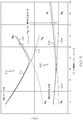
FIG. 5 is a graph illustrating pressurization performance of the flow divider assembly ofFIGS. 2-4 in accordance with an exemplary embodiment. - The following detailed description is merely exemplary in nature and is not intended to limit the invention or the application and uses of the invention. As used herein, the word "exemplary" means "serving as an example, instance, or illustration." Thus, any embodiment described herein as "exemplary" is not necessarily to be construed as preferred or advantageous over other embodiments. All of the embodiments described herein are exemplary embodiments provided to enable persons skilled in the art to make or use the invention and not to limit the scope of the invention which is defined by the claims. Furthermore, there is no intention to be bound by any expressed or implied theory presented in the preceding technical field, background, brief summary, or the following detailed description.
- Broadly, exemplary embodiments discussed herein are directed to a fuel control system for delivering fuel to the combustor of a gas turbine engine. The fuel control system includes a flow divider assembly that selectively distributes fuel between the fuel nozzles of the combustor, particularly between main nozzles, nonenriched pilot nozzles, and enriched pilot nozzles. In one exemplary embodiment, the flow divider assembly includes a flow divider valve that that initially divides the fuel between the main nozzles and the pilot nozzles at a predetermined proportion. A flow balancing valve is downstream of the flow divider valve and equalizes the pressures of the apportioned fuel flows while maintaining the predetermined proportion from the flow divider valve. The flow balancing valve further includes a spring element that maintains a minimum pressurization downstream of the flow divider valve and allows both balancing valve elements to open with increasing flow to minimize pressure losses across the valve at engine high power conditions. The portion of fuel for the pilot nozzles is subsequently directed back to the flow divider valve and is selectively subdivided into conduits that deliver fuel to the nonenriched pilot nozzles and to the enriched pilot nozzles.
-
FIG. 1 is a simplified block diagram of an exemplaryfuel control system 100 for acombustor 182 of agas turbine engine 180 in accordance with an exemplary embodiment. Thegas turbine engine 180 may be, for example, an aircraft engine with any number of fans, compressor, turbines, and the like for extracting energy from burned fuel. Thefuel control system 100 may include afuel tank 110, a fuel supply andmetering assembly 120, and aflow divider assembly 130. Theflow divider assembly 130 is further coupled to at least two sets ofnozzles combustor 182. In one exemplary embodiment, thenozzles main nozzles 142 andpilot nozzles 144. Thepilot nozzles 144 may be further grouped into enrichedpilot nozzles 146 andnonenriched pilot nozzles 148. Thefuel control system 100 further includes acontroller 150 coupled to the fuel supply andmetering assembly 120 and theflow divider assembly 130 for controlling operation of thefuel control system 100, as discussed in greater detail below. - During operation, the fuel supply and
metering assembly 120 provides theflow divider assembly 130 with metered quantities of fuel withdrawn from thefuel tank 110 according to control signals provided by thecontroller 150. Theflow divider assembly 130 then apportions the metered fuel received from fuel supply andmetering assembly 120 between themain nozzles 142, the enrichedpilot nozzles 146, and thenonenriched pilot nozzles 148 according to control signals provided by thecontroller 150. Although not shown, the fuel supply andmetering assembly 120 may include various components suitable for providing thecombustor 182 with metered fuel in this manner including, but not limited to, one or more boost pumps, high pressure pumps, filters, bypass valves, metering valves, pressurizing valves, and the like. Additionally, in some embodiments, the fuel supply andmetering assembly 120 may be separated into a supply assembly and a metering assembly. - The predetermined apportionment of fuel flow between the
main nozzles 142, enrichedpilot nozzles 146, andnonenriched pilot nozzles 148 may be a function of engine condition or demands. For example, during initial start-up, it may be desirable to direct a large portion of the fuel flow to the enrichedpilot nozzles 146 to initiate ignition in thecombustor 182. As start-up continues, the proportion of fuel flow to thenonenriched pilot nozzles 148 may be increased. Further, during normal operating conditions, the fuel flow may be more evenly distributed between themain nozzles 142, enrichedpilot nozzles 146, andnonenriched pilot nozzles 148, and during high power operation, a greater proportion may be distributed to themain nozzles 142. Thecontroller 150 generally provides signals for the desired distribution based on operator commands, engine conditions, and/or engine feedback. -
FIG. 2 is a schematic diagram of aflow divider assembly 130 of thefuel control system 100 ofFIG. 1 in a first position in accordance with an exemplary embodiment. Theflow divider assembly 130 generally includes aflow dividing valve 220 and a balancingvalve 270 positioned within ahousing 202. AlthoughFIG. 2 depicts theflow dividing valve 220 and the balancingvalve 270 positioned within thesingle housing 202, in other embodiments, theflow dividing valve 220 and balancingvalve 270 may be separated into separate housings. Theflow divider assembly 130 further includes a number ofconduits inlet 204 of theflow divider assembly 130, theflow dividing valve 220, thebalancing valve 270, and finally, thenozzles - In one exemplary embodiment, the
flow dividing valve 220 may be a cylindrical or spool-type valve that includes acavity 222 formed in thehousing 202 and apiston device 250. Thecavity 222 is generally a longitudinal channel defined byend walls side walls side walls ports flow dividing valve 220, as described in greater detail below. - The
piston device 250 is formed bypistons rod 258. In one exemplary embodiment thepistons rod 258 to divide thecavity 222 into first, second, third, andfourth cavity sections first cavity section 260 is defined between thefirst piston 252 and theend wall 224; thesecond cavity section 262 is defined between thefirst piston 252 and thesecond piston 254; thethird cavity section 264 is defined between thesecond piston 254 and thethird piston 256; and thefourth cavity section 266 is defined between thethird piston 256 and theend wall 226. - The
rod 258 and thepistons cavity 222 such that thepistons ports main nozzles 142, enrichedpilot nozzles 146, andnonenriched pilot nozzles 148. In the depiction ofFIG. 2 as well as discussed below, the position of thepiston device 250 is described with reference todistance 300, which is the distance between a first edge of theport 236 and thesecond piston 254. The positions of thepiston device 250 and the resulting fuel flows are discussed in greater detail below. -
Conduits second cavity section 262 of theflow dividing valve 220 to the balancingvalue 270. The balancingvalve 270 may be a cylindrical or spool-type valve that includes alongitudinal cavity 272 formed byend walls side walls 278 and 280. In the depicted embodiment,ports end walls ports side wall 278. Abalancing device 290 is positioned within thecavity 272 to divide thecavity 272 into afirst cavity section 302, asecond cavity section 304, and a third,middle cavity section 306. Thefirst cavity section 302 is defined by thebalancing device 290 and theend wall 274, thesecond cavity 304 is defined by thebalancing device 290 and theend wall 276, and thethird cavity 306 is defined as the region within thebalancing device 290. - The
balancing device 290 of the balancingvalve 270 is formed by afirst element 292 and asecond element 294 coupled together with aspring element 296. As shown, the first andsecond elements cavity 272. Particularly, thespring element 296 urges the first andsecond elements second elements spring element 296. The first andsecond elements spring element 296 until forced againstrespective end walls second elements first element 292 andsecond element 294 contact one another. The first andsecond elements spring element 296 may also translate together within thecavity 272. As shown inFIG. 2 and discussed below, the first andsecond elements ports - When
port 286 is at least partially uncovered,conduit 212 fluidly couples thefirst cavity section 302 of the balancingvalve 270 to themain nozzles 142 of thecombustor 182, as discussed above. Whenport 288 is at least partially uncovered,conduit 214 fluidly couples thesecond cavity section 304 of the balancingvalve 270 to thethird cavity section 264 of theflow dividing valve 220.Port 287 is open at all balancing device operating positions and fluidically couplesmiddle cavity 306 toconduit 213 which is in turn coupled toconduit 214. - Based on the positions of the
pistons third cavity section 264 of theflow dividing valve 220 is selectively in fluid communication with theconduits ports port 242 intoconduit 218 is delivered to the enrichedpilot nozzles 146, and the fuel flowing throughport 240 intoconduit 216 is delivered to thenonenriched pilot nozzles 148. - Now that the general structure and flow paths of fuel in the
fuel divider assembly 130 have been described, further details about the operation of theflow dividing valve 220 and balancingvalve 270 will now be discussed. Throughout the description below, the following acronyms are used to denote various reference pressures and flow rates: - P22
- Pressure at
inlet 204 - WfN
- Flow rate at
inlet 204 - WfNm
- Main nozzle flow rate in
conduit - WfNp
- Pilot nozzle flow rate in
conduits - PMm'
- Pressure of main nozzle flow in
conduit 208 - PMp'
- Pressure of pilot nozzle flow in
conduit 210 - PMm
- Pressure at
main nozzles 142 - PMp
- Pressure of pilot nozzle flow in
conduit 214 - WfNpne
- Flow rate at
nonenriched pilot nozzles 148 - PMpne
- Pressure at
nonenriched pilot nozzles 148 - WfNpe
- Flow rate at enriched
pilot nozzles 146 - PMpe
- Pressure at enriched
pilot nozzles 146 - As noted above, the
flow divider assembly 130 receives fuel from the fuel supply andmetering assembly 120 viainlet 204. Theinlet 204 is fluidly coupled to theflow dividing valve 220 atport 244 such that fuel initially flows into thesecond cavity section 262 ofcavity 222 at pressure (P22) and flow rate (WfN). Thesecond cavity section 262 is fluidly coupled to one or both of theconduits ports piston device 250. As shown inFIG. 2 , thefirst piston 252 is configured to selectively block all or a portion ofport 234, and thesecond piston 254 is configured to selectively block all or a portion ofport 236. Since the position of thefirst piston 252 is fixed relative to the position of thesecond piston 254, thepistons first piston 252 moves to cover the port 234 (e.g., in the right hand direction ofFIG. 2 to increase distance 300), thesecond piston 254 uncovers theport 236. Generally, theports pistons pistons ports piston 252 may be positioned to at least partially block theport 234, and thepiston 254 may be positioned to at least partially block theport 236. In any given position, the unblocked portion ofport 234 corresponds to the blocked portion ofport 236, and vice versa. Moreover, any change in the blocked or unblocked cross-sectional areas respectively results in a corresponding change to the unblocked or blocked cross sectional areas. - As such, by positioning the
piston device 250, theflow dividing valve 220 may apportion a first portion (WfNm) of the fuel ("main nozzle fuel" or "primary/main circuit") at a pressure (PMm') throughport 234 toconduit 208 and a second portion (WfNp) of the fuel ("pilot nozzle fuel" or "secondary/pilot circuit") at a pressure (PMp') throughport 236 toconduit 210. In the position depicted byFIG. 2 , the first andsecond pistons port port 236. However, thepiston device 250 may move to apportion the fuel flow in any desired percentage amount, e.g., such as 40%/60%, 30%/70%, and so on. As described above, thecontroller 150 may provide signals to translate thepiston device 250 into any position to provide the desired proportion of fuel to thenozzles flow dividing valve 220 to thenozzles - As also shown in
FIG. 2 , theflow dividing valve 220 may include asensor 261 and anactuator 267 that function to position thepiston device 250 based on commands from the controller 150 (FIG. 1 ). In one exemplary embodiment, thesensor 261 may be a linear variable differential transformer (LVDT). In the embodiment depicted inFIG. 2 , theLVDT 261 is coupled to thepiston device 250, particularly topiston 252, to determine the position of thepiston device 250. TheLVDT 261 may provide an indication of the position of thepiston device 250 in thecavity 222 to the controller 150 (FIG. 1 ). Theactuator 267 may be, for example, an electrohydraulic servo valve (EHSV) that modulates the pressures within thecavity sections piston device 250 based on control signals from thecontroller 150. As such, theLVDT 261 andEHSV 267 cooperate to maintain or adjust thepiston device 150 into the appropriate position for delivering a desired proportion of fuel to the selectednozzles - The
conduit 208 delivers main nozzle fuel to the balancingvalve 270 viaport 282, and theconduit 210 delivers the pilot nozzle valve fuel to the balancingvalve 270 viaport 284. Particularly, the main nozzle fuel is directed to thefirst cavity section 302 and the pilot nozzle fuel is directed to thesecond cavity section 304. - The balancing
valve 270 functions to equalize the pressures of the pilot nozzle fuel and the main nozzle fuel and to maintain the predetermined split of fuel from theflow dividing valve 220 independent of the total fuel magnitude (e.g., WfN) and independent of variations in downstream pressures (e.g., changes in PMm, PMp, PMpne, and PMpe). As noted above, thebalancing device 290 includes twoelements spring element 296. Since theelements spring element 296 in thecavity 272, the pressures incavities elements cavity section balancing device 290 towards theother cavity section ports 234 and 236 (e.g., WfNm and WfNp) as a percentage of total flow (WfN) is directly dependent on the relationship between the open areas ofports ports - In addition to maintaining the flow distribution (WfNm to WfNp) and equalizing pressures (PMm' and PMp'), the balancing
valve 270 also maintains a minimum pressurization for the flowing nozzle circuits by maintaining a minimum pressure of fuel inconduits 208 and/or 210. This pressure potential can be useful in powering supplemental parallel flow circuits, e.g. those used for cooling or motive flow. Thespring element 296 biases theelements ports valve 220, thespring element 296 biases theelements respective end walls ports middle cavity 306 of the balancingvalve 270 byconduit 213 andport 287, to overcome the predetermined spring force, translatingelement ports spring element 296 provides a minimum upstream pressurization relative to the downstream pilot nozzle circuit pressure (PMp). In one exemplary embodiment, the minimum pressurization may be, for example, 20 psid. As flow levels increase in the main and pilot circuits,elements spring element 296, further openingports valve 270 at high flows are minimized to prevent over-pressurizing the upstream components. Furthermore, once gap 298 is closed,elements balancing valve component 270. - As such, with both main and pilot circuits flowing, the main pressure (PMm') at the inlet of the balancing
valve 270 inconduit 208 is equal to the pilot pressure (PMp') at the inlet of the balancingvalve 270. Additionally, main flow rate (WfNm) inconduit 208 is equal to the main flow rate (WfNm) inconduit 212, and pilot flow rate (WfNp) inconduit 210 is equal to the pilot flow rate (WfNp) inconduit 214. The proportion of the main flow rate and pilot flow rate (WfNm to WfNp) is maintained downstream of theflow dividing valve 220 throughout theflow divider assembly 130. - As noted above, the main nozzle fuel flows through
conduit 212 and out of theflow divider assembly 130 to themain nozzles 142. The pilot nozzle fuel flows throughconduit 214 to thethird cavity section 264 of the balancingvalve 270. In the balancingvalve 270, thepiston 254 is positioned on thepiston rod 258 to selectively cover and uncoverport 240. Thepiston 254 is particularly positioned to provide a desired proportion of the pilot fuel (WfNp) to theconduit 216 as nonenriched pilot fuel (WfNpne) and theconduit 218 as enriched pilot fuel (WfNpe). In this manner, the controller 150 (FIG. 1 ) may provide a greater amount of fuel to the enrichedpilot nozzles 146 as necessary or desired based on feedback, operating conditions, and/or operator control. - Although not shown, a second balancing valve may be provided between the dividing
valve 220 and thepilot nozzles flow balancing valve 270 and equalize the pressures in the pilotnozzle flow conduits 216 and 218 (e.g., pressures PMpne and PMpe) to maintain the predetermined apportionment of fuel between the enrichedpilot nozzles 146 and thenonenriched pilot nozzles 148. - Other positions are illustrated in
FIGS. 3 and4 . For example, as shown inFIG. 3 , thepiston device 250 has been positioned such that thefirst piston 252 completely covers theport 234 such that 100% of the fuel (WfN) flows into the conduit 210 (e.g., as WfNp) to be subsequently provided to thepilot nozzles 144. As also shown inFIG. 3 , thesecond piston 254 is positioned such that an equal amount of fuel flows into theconduit 216 for thenonenriched pilot nozzles 148 and into theconduit 218 for the enrichedpilot nozzles 146. As also shown inFIG. 3 , with zero flow inconduit 208,element 292 of balancingvalve 270 is closed, biased byspring 296 againstend wall 274. InFIG. 4 , thedevice 250 has been positioned such that thefirst piston 252 completely covers theport 234 such that 100% of the fuel (WfN) flows into theconduit 210 to be subsequently provided to the enrichedpilot nozzles 146. However, in contrast toFIG. 3 , thesecond piston 254 inFIG. 4 is positioned such that thesecond piston 254 covers theport 240 to thenonenriched pilot nozzles conduit 218 for the enriched pilot nozzles 146 (e.g., as WfNpe). -
FIG. 5 is a graph illustrating pressurization performance of the flow divider assembly, such as the flow divider assembly ofFIGS. 2-4 , which are also referenced below. InFIG. 5 , pressure is represented on the vertical axis and the split between the pilot and main circuits (expressed as the percentage of pilot circuit flow (WfNp) relative to the total flow (WfN)) is represented on the horizontal axis. Representative data is shown for the max totalmetered flow case 510 and medium totalmetered flow case 530.Line 512 represents the change in pilot flow pressure (PMp') in theconduit 210 as a function of the percentage of pilot flow.Line 514 represents the change in main flow pressure (PMm) at thenozzles 142 as a function of the percentage of pilot flow.Line 516 represents the change in pilot flow pressure (PMp) inconduit 214 as a function of the percentage of pilot flow. As shown, the difference between the pilot flow pressure (PMp') in theconduit 210 and pilot flow pressure (PMp) inconduit 214 corresponds to at least the minimum pressurization enabled by the balancingvalve 270, yet does not exceed the greater of the two downstream nozzle-generated back pressures (PMp or PMm) by a significantly larger amount at any point in the displayed operating envelope. Similarly,line 532 represents the change in pilot flow pressure (PMp') in theconduit 210 as a function of the percentage of pilot flow.Line 534 represents the change in main flow pressure (PMm) at thenozzles 142 as a function of the percentage of pilot flow.Line 536 represents the change in pilot flow pressure (PMp) inconduit 214 as a function of the percentage of pilot flow. As shown, the difference between the pilot flow pressure (PMp') in theconduit 210 and pilot flow pressure (PMp) inconduit 214 corresponds to at least the minimum pressurization enabled by the balancingvalve 270, yet does not exceed the greater of the two downstream nozzle-generated back pressures (PMp or PMm) by a significantly larger amount at any point in the displayed operating envelope. - Accordingly, a fuel control system with a flow divider assembly is provided. The flow divider valve initially divides the fuel between the main nozzles and the pilot nozzles at a predetermined proportion. The flow balancing valve is downstream of the flow divider valve and equalizes the pressures of the apportioned fuel flows while maintaining the predetermined proportion from the flow divider valve. The flow balancing valve further includes a spring element that maintains a minimum pressurization downstream of the flow dividing valve and minimizes excessive pressure losses at high flow conditions. The portion of fuel for the pilot nozzles is subsequently directed back to the flow divider valve and is selectively subdivided into conduits that deliver fuel to the nonenriched pilot nozzles and to the enriched pilot nozzles. In one exemplary embodiment, the flow divider assembly is provided in a single housing to apportion fuels between the main fuel nozzles, the nonenriched pilot fuel nozzles, and the enriched pilot fuel nozzles in a predictable proportion independent of total flow magnitude and downstream pressure variations.
- While at least one exemplary embodiment has been presented in the foregoing detailed description of the invention, it should be appreciated that a vast number of variations exist. It should also be appreciated that the exemplary embodiment or exemplary embodiments are only examples, and are not intended to limit the applicability, or configuration of the invention in any way. Rather, the foregoing detailed description will provide those skilled in the art with a convenient road map for implementing an exemplary embodiment of the invention. It being understood that various changes may be made in the function and arrangement of elements described in an exemplary embodiment without departing from the invention as set forth in the appended claims.
Claims (8)
- A flow divider assembly (130), comprising:a dividing valve (220) comprising:a dividing cavity (222) configured to receive a flow of fuel, the dividing cavity (222) including a first dividing valve port (234) and a second dividing valve port (236), anda piston device (250) arranged within the dividing cavity (222) and selectively positioned to divide the flow of fuel in the dividing cavity (222) such that a first portion of the flow is directed into the first dividing valve port (234) and a second portion of the flow is directed into the second dividing valve port (236); anda balancing valve (270) fluidly coupled to the dividing valve (220) and configured to receive the first portion of the flow at a first pressure and the second portion of the flow at a second pressure, the balancing valve (270) comprising:a balancing cavity (272) including a first balancing cavity port (286) and a second balancing cavity port (288), anda balancing device (290) arranged within the balancing cavity (272) and selectively positioned to direct the first portion of the flow into the first balancing cavity port (286) at a third pressure and the second portion of the flow into the second balancing cavity port (288) at a fourth pressure such that the first pressure is approximately equal to the second pressure, characterized in that; the piston device (250) comprises a rod (258) and a first piston (252) and a second piston (254) arranged in fixed positions on the rod (258), and the first piston (252), second piston (254), and rod (258) are configured to translate with one another within the dividing cavity (222) such that the first piston (252) selectively blocks the first dividing cavity port (234) and the second piston (254) selectively blocks the second dividing cavity port (236), andthe dividing cavity (222) further comprises a third dividing valve port (240) and a fourth dividing valve port (242), and wherein the dividing cavity (222) is fluidly coupled to the second balancing valve port (288) to receive the second portion of flow and is further configured to divide the second portion of flow such that a third portion of flow is directed into the third dividing valve port (240) and a fourth portion of flow is directed into the fourth dividing valve port (242).
- The flow divider assembly (130) of claim 1, wherein the dividing cavity (222) is configured to divide the first portion of the flow and the second portion of the flow into a predetermined proportion.
- The flow divider assembly (130) of claim 2, wherein the balancing valve (270) is configured to maintain the predetermined proportion independent of the third pressure and the fourth pressure.
- The flow divider assembly (130) of claim 2, wherein the balancing valve (270) is configured to maintain the predetermined proportion independent of a total magnitude of the flow.
- The flow divider assembly (130) of claim 1 , wherein, in a first position, the first piston (252) partially blocks the first dividing valve port (234) to form a first blocked cross-sectional area and a first unblocked cross-sectional area and the second piston (254) partially blocks the second dividing valve port (236) to form a second blocked cross-sectional area and a second unblocked cross-sectional area, and wherein the first blocked cross-sectional area is equal to the second unblocked cross-sectional area.
- The flow divider assembly (130) of claim 5, wherein the piston device (250) is configured to translate such that a change in the first blocked cross-sectional area is equal to a change in the second unblocked cross-sectional area.
- The flow divider assembly (130) of claim 1 , wherein the piston device (250) further comprises third piston (256) arranged on the rod (258), and wherein the second piston (254), the third piston (256), and the rod (258) are configured to translate with one another within the dividing cavity (222) such that the second piston (254) selectively blocks the third dividing valve port (240).
- The flow divider assembly (130) of claim 1, wherein the balancing valve (270) comprises a first balancing valve element (292), a second balancing element (294), and a spring element (306) biasing the first balancing valve element (292) away from the second balancing valve element (294).
Applications Claiming Priority (1)
| Application Number | Priority Date | Filing Date | Title |
|---|---|---|---|
| US13/159,175 US8464740B2 (en) | 2011-06-13 | 2011-06-13 | Combustor fuel control systems with flow divider assemblies |
Publications (3)
| Publication Number | Publication Date |
|---|---|
| EP2535644A2 EP2535644A2 (en) | 2012-12-19 |
| EP2535644A3 EP2535644A3 (en) | 2017-12-13 |
| EP2535644B1 true EP2535644B1 (en) | 2018-10-24 |
Family
ID=46148700
Family Applications (1)
| Application Number | Title | Priority Date | Filing Date |
|---|---|---|---|
| EP12169406.1A Not-in-force EP2535644B1 (en) | 2011-06-13 | 2012-05-24 | Combustor fuel control systems with flow divider assemblies |
Country Status (3)
| Country | Link |
|---|---|
| US (1) | US8464740B2 (en) |
| EP (1) | EP2535644B1 (en) |
| CN (1) | CN102829488B (en) |
Families Citing this family (12)
| Publication number | Priority date | Publication date | Assignee | Title |
|---|---|---|---|---|
| CN103090409A (en) * | 2013-01-31 | 2013-05-08 | 佛山市沛沣科技有限公司 | Powder combustion system actuator |
| FR3010141B1 (en) * | 2013-09-03 | 2018-01-05 | Safran Aircraft Engines | FUEL SYSTEM WITH MULTIPOINT INJECTORS FOR A TURBOMACHINE |
| FR3010139B1 (en) * | 2013-09-04 | 2019-05-17 | Safran Aircraft Engines | DEVICE AND METHOD FOR ESTIMATING CLAMPS IN A FUEL INJECTION SYSTEM IN A COMBUSTION CHAMBER OF AN ENGINE |
| US9689318B1 (en) * | 2014-12-02 | 2017-06-27 | Jansen's Aircraft Systems Controls, Inc. | Equilibrating flow distributor |
| US11261803B2 (en) | 2020-03-05 | 2022-03-01 | General Electric Company | Method and system for fuel nozzle cleaning during engine operation |
| US11359554B2 (en) | 2020-03-05 | 2022-06-14 | General Electric Company | System and method for fuel nozzle cleaning during engine operation |
| EP3889409B1 (en) * | 2020-03-30 | 2024-04-24 | Hamilton Sundstrand Corporation | Flow divider valves with transient pressure limiting |
| US20210301766A1 (en) * | 2020-03-30 | 2021-09-30 | Hamilton Sundstrand Corporation | Regulated flow divider valves |
| EP3889408B1 (en) * | 2020-03-30 | 2024-04-24 | Hamilton Sundstrand Corporation | Regulated flow divider valves with secondary equalization valves |
| CN111913504B (en) * | 2020-08-17 | 2023-10-20 | 中国地质大学(北京) | Constant flow dividing device |
| US11946378B2 (en) | 2022-04-13 | 2024-04-02 | General Electric Company | Transient control of a thermal transport bus |
| US11927142B2 (en) | 2022-07-25 | 2024-03-12 | General Electric Company | Systems and methods for controlling fuel coke formation |
Family Cites Families (25)
| Publication number | Priority date | Publication date | Assignee | Title |
|---|---|---|---|---|
| US3033277A (en) * | 1955-05-09 | 1962-05-08 | Holley Carburetor Co | Fuel supply system |
| US2953150A (en) * | 1956-06-21 | 1960-09-20 | Allen V C Davis | Flow proportioning device |
| DE2751082C2 (en) | 1977-11-16 | 1982-12-02 | Zahnradfabrik Friedrichshafen Ag, 7990 Friedrichshafen | Flow divider valve for a hydraulic system |
| US4465089A (en) * | 1982-09-29 | 1984-08-14 | Mag-Dynamics, Inc. | Flow divider and combiner for traction circuits |
| US4691730A (en) | 1986-09-19 | 1987-09-08 | Allied Corporation | Constant percentage flow divider |
| CN1020206C (en) * | 1988-11-28 | 1993-03-31 | 通用电气公司 | Gas fuel dividing device for gas turbine combustion chambers |
| US4949538A (en) * | 1988-11-28 | 1990-08-21 | General Electric Company | Combustor gas feed with coordinated proportioning |
| US5321949A (en) | 1991-07-12 | 1994-06-21 | General Electric Company | Staged fuel delivery system with secondary distribution valve |
| US5339636A (en) | 1992-12-04 | 1994-08-23 | United Technologies Corporation | Fuel splitter valve assembly for gas turbine |
| US5442922A (en) | 1993-12-09 | 1995-08-22 | United Technologies Corporation | Fuel staging system |
| US5448882A (en) | 1993-12-14 | 1995-09-12 | United Technologies Corporation | Fuel metering system |
| US6092546A (en) | 1997-12-12 | 2000-07-25 | Alliedsignal Inc. | Fuel flow divider and pressurizing valve for gas turbine |
| US6250063B1 (en) * | 1999-08-19 | 2001-06-26 | General Electric Co. | Fuel staging apparatus and methods for gas turbine nozzles |
| US6637184B2 (en) | 2002-01-24 | 2003-10-28 | Siemens Westinghouse Power Corporation | Flow control system for liquid fuel engine having stage-specific control of fuel flow to several groups of nozzles in the engine |
| US6892544B2 (en) | 2002-04-29 | 2005-05-17 | Honeywell International Inc. | Flow divider & purge air system for a gas turbine engine |
| US6751939B2 (en) | 2002-06-25 | 2004-06-22 | Honeywell International Inc. | Flow divider and ecology valve |
| JP2004144004A (en) * | 2002-10-24 | 2004-05-20 | Sanoh Industrial Co Ltd | Fuel delivery pipe |
| FR2846757B1 (en) * | 2002-10-30 | 2006-07-14 | Framatome Anp | PASSIVE DEVICE FOR BALANCING THE PRESSURE OF A FIRST AND A SECOND FLUID AND USE THEREOF |
| GB0329626D0 (en) | 2003-12-23 | 2004-01-28 | Goodrich Control Sys Ltd | Fuel system |
| US7036302B2 (en) | 2004-03-15 | 2006-05-02 | General Electric Company | Controlled pressure fuel nozzle system |
| EP1906091A2 (en) * | 2006-09-26 | 2008-04-02 | United Technologies Corporation | Flow divider valve |
| US8157241B2 (en) * | 2008-02-29 | 2012-04-17 | General Electric Company | Methods and apparatus for regulating gas turbine engine fluid flow |
| US8353306B2 (en) | 2008-08-12 | 2013-01-15 | Honeywell International Inc. | Fuel divider system for gas turbine engine |
| US8316630B2 (en) | 2008-08-27 | 2012-11-27 | Honeywell International Inc. | Flow equalizing override assembly for fuel divider system |
| US8820087B2 (en) | 2008-09-08 | 2014-09-02 | Siemens Energy, Inc. | Method and system for controlling fuel to a dual stage nozzle |
-
2011
- 2011-06-13 US US13/159,175 patent/US8464740B2/en active Active
-
2012
- 2012-05-24 EP EP12169406.1A patent/EP2535644B1/en not_active Not-in-force
- 2012-06-12 CN CN201210191823.8A patent/CN102829488B/en active Active
Non-Patent Citations (1)
| Title |
|---|
| None * |
Also Published As
| Publication number | Publication date |
|---|---|
| EP2535644A2 (en) | 2012-12-19 |
| US8464740B2 (en) | 2013-06-18 |
| CN102829488B (en) | 2016-02-24 |
| US20120312378A1 (en) | 2012-12-13 |
| EP2535644A3 (en) | 2017-12-13 |
| CN102829488A (en) | 2012-12-19 |
Similar Documents
| Publication | Publication Date | Title |
|---|---|---|
| EP2535644B1 (en) | Combustor fuel control systems with flow divider assemblies | |
| US6981359B2 (en) | Centrifugal pump fuel system and method for gas turbine engine | |
| EP2744996B1 (en) | Split control unit | |
| JP5666604B2 (en) | Fuel supply circuit for aero engines | |
| JP5539525B2 (en) | Fuel supply circuit for aero engines | |
| US9234465B2 (en) | Fuel flow divider and ecology system for a gas turbine engine fuel flow control system | |
| EP2318690B1 (en) | System for metering a fuel supply | |
| EP2497923B1 (en) | Fuel system | |
| US8951021B2 (en) | Dual pump/dual bypass fuel pumping system | |
| EP2295767B1 (en) | An aerospace fuel metering unit (FMU) | |
| US9140190B2 (en) | Gas turbine engine fuel metering valve adapted to selectively receive fuel flow increase/decrease commands from the engine control and from the back-up fuel control | |
| US20140069102A1 (en) | Gas turbine engine fuel system metering valve | |
| US7950232B2 (en) | Fuel feed circuit for an aircraft engine | |
| CN107074374B (en) | Pump authority switching device for fluid distribution system | |
| EP2175119B1 (en) | Combined metering valve and pressure regulating valve | |
| US11781483B1 (en) | Minimum pressure valve for aircraft fuel system | |
| RU2476702C2 (en) | Gas turbine engine fuel feed system |
Legal Events
| Date | Code | Title | Description |
|---|---|---|---|
| PUAI | Public reference made under article 153(3) epc to a published international application that has entered the european phase |
Free format text: ORIGINAL CODE: 0009012 |
|
| 17P | Request for examination filed |
Effective date: 20120524 |
|
| AK | Designated contracting states |
Kind code of ref document: A2 Designated state(s): AL AT BE BG CH CY CZ DE DK EE ES FI FR GB GR HR HU IE IS IT LI LT LU LV MC MK MT NL NO PL PT RO RS SE SI SK SM TR |
|
| AX | Request for extension of the european patent |
Extension state: BA ME |
|
| RAP1 | Party data changed (applicant data changed or rights of an application transferred) |
Owner name: HONEYWELL INTERNATIONAL INC. |
|
| PUAL | Search report despatched |
Free format text: ORIGINAL CODE: 0009013 |
|
| STAA | Information on the status of an ep patent application or granted ep patent |
Free format text: STATUS: EXAMINATION IS IN PROGRESS |
|
| AK | Designated contracting states |
Kind code of ref document: A3 Designated state(s): AL AT BE BG CH CY CZ DE DK EE ES FI FR GB GR HR HU IE IS IT LI LT LU LV MC MK MT NL NO PL PT RO RS SE SI SK SM TR |
|
| AX | Request for extension of the european patent |
Extension state: BA ME |
|
| RIC1 | Information provided on ipc code assigned before grant |
Ipc: F02C 7/228 20060101ALI20171109BHEP Ipc: F23K 5/14 20060101ALI20171109BHEP Ipc: F23K 5/06 20060101AFI20171109BHEP Ipc: F23N 1/00 20060101ALI20171109BHEP |
|
| 17Q | First examination report despatched |
Effective date: 20171128 |
|
| GRAP | Despatch of communication of intention to grant a patent |
Free format text: ORIGINAL CODE: EPIDOSNIGR1 |
|
| STAA | Information on the status of an ep patent application or granted ep patent |
Free format text: STATUS: GRANT OF PATENT IS INTENDED |
|
| INTG | Intention to grant announced |
Effective date: 20180531 |
|
| GRAS | Grant fee paid |
Free format text: ORIGINAL CODE: EPIDOSNIGR3 |
|
| GRAA | (expected) grant |
Free format text: ORIGINAL CODE: 0009210 |
|
| STAA | Information on the status of an ep patent application or granted ep patent |
Free format text: STATUS: THE PATENT HAS BEEN GRANTED |
|
| AK | Designated contracting states |
Kind code of ref document: B1 Designated state(s): AL AT BE BG CH CY CZ DE DK EE ES FI FR GB GR HR HU IE IS IT LI LT LU LV MC MK MT NL NO PL PT RO RS SE SI SK SM TR |
|
| REG | Reference to a national code |
Ref country code: GB Ref legal event code: FG4D |
|
| REG | Reference to a national code |
Ref country code: CH Ref legal event code: EP |
|
| REG | Reference to a national code |
Ref country code: IE Ref legal event code: FG4D |
|
| REG | Reference to a national code |
Ref country code: AT Ref legal event code: REF Ref document number: 1057120 Country of ref document: AT Kind code of ref document: T Effective date: 20181115 |
|
| REG | Reference to a national code |
Ref country code: DE Ref legal event code: R096 Ref document number: 602012052498 Country of ref document: DE |
|
| REG | Reference to a national code |
Ref country code: NL Ref legal event code: MP Effective date: 20181024 |
|
| REG | Reference to a national code |
Ref country code: LT Ref legal event code: MG4D |
|
| REG | Reference to a national code |
Ref country code: AT Ref legal event code: MK05 Ref document number: 1057120 Country of ref document: AT Kind code of ref document: T Effective date: 20181024 |
|
| PG25 | Lapsed in a contracting state [announced via postgrant information from national office to epo] |
Ref country code: NL Free format text: LAPSE BECAUSE OF FAILURE TO SUBMIT A TRANSLATION OF THE DESCRIPTION OR TO PAY THE FEE WITHIN THE PRESCRIBED TIME-LIMIT Effective date: 20181024 |
|
| PG25 | Lapsed in a contracting state [announced via postgrant information from national office to epo] |
Ref country code: LV Free format text: LAPSE BECAUSE OF FAILURE TO SUBMIT A TRANSLATION OF THE DESCRIPTION OR TO PAY THE FEE WITHIN THE PRESCRIBED TIME-LIMIT Effective date: 20181024 Ref country code: LT Free format text: LAPSE BECAUSE OF FAILURE TO SUBMIT A TRANSLATION OF THE DESCRIPTION OR TO PAY THE FEE WITHIN THE PRESCRIBED TIME-LIMIT Effective date: 20181024 Ref country code: ES Free format text: LAPSE BECAUSE OF FAILURE TO SUBMIT A TRANSLATION OF THE DESCRIPTION OR TO PAY THE FEE WITHIN THE PRESCRIBED TIME-LIMIT Effective date: 20181024 Ref country code: NO Free format text: LAPSE BECAUSE OF FAILURE TO SUBMIT A TRANSLATION OF THE DESCRIPTION OR TO PAY THE FEE WITHIN THE PRESCRIBED TIME-LIMIT Effective date: 20190124 Ref country code: AT Free format text: LAPSE BECAUSE OF FAILURE TO SUBMIT A TRANSLATION OF THE DESCRIPTION OR TO PAY THE FEE WITHIN THE PRESCRIBED TIME-LIMIT Effective date: 20181024 Ref country code: IS Free format text: LAPSE BECAUSE OF FAILURE TO SUBMIT A TRANSLATION OF THE DESCRIPTION OR TO PAY THE FEE WITHIN THE PRESCRIBED TIME-LIMIT Effective date: 20190224 Ref country code: FI Free format text: LAPSE BECAUSE OF FAILURE TO SUBMIT A TRANSLATION OF THE DESCRIPTION OR TO PAY THE FEE WITHIN THE PRESCRIBED TIME-LIMIT Effective date: 20181024 Ref country code: HR Free format text: LAPSE BECAUSE OF FAILURE TO SUBMIT A TRANSLATION OF THE DESCRIPTION OR TO PAY THE FEE WITHIN THE PRESCRIBED TIME-LIMIT Effective date: 20181024 Ref country code: BG Free format text: LAPSE BECAUSE OF FAILURE TO SUBMIT A TRANSLATION OF THE DESCRIPTION OR TO PAY THE FEE WITHIN THE PRESCRIBED TIME-LIMIT Effective date: 20190124 Ref country code: PL Free format text: LAPSE BECAUSE OF FAILURE TO SUBMIT A TRANSLATION OF THE DESCRIPTION OR TO PAY THE FEE WITHIN THE PRESCRIBED TIME-LIMIT Effective date: 20181024 |
|
| PG25 | Lapsed in a contracting state [announced via postgrant information from national office to epo] |
Ref country code: GR Free format text: LAPSE BECAUSE OF FAILURE TO SUBMIT A TRANSLATION OF THE DESCRIPTION OR TO PAY THE FEE WITHIN THE PRESCRIBED TIME-LIMIT Effective date: 20190125 Ref country code: RS Free format text: LAPSE BECAUSE OF FAILURE TO SUBMIT A TRANSLATION OF THE DESCRIPTION OR TO PAY THE FEE WITHIN THE PRESCRIBED TIME-LIMIT Effective date: 20181024 Ref country code: SE Free format text: LAPSE BECAUSE OF FAILURE TO SUBMIT A TRANSLATION OF THE DESCRIPTION OR TO PAY THE FEE WITHIN THE PRESCRIBED TIME-LIMIT Effective date: 20181024 Ref country code: PT Free format text: LAPSE BECAUSE OF FAILURE TO SUBMIT A TRANSLATION OF THE DESCRIPTION OR TO PAY THE FEE WITHIN THE PRESCRIBED TIME-LIMIT Effective date: 20190224 Ref country code: AL Free format text: LAPSE BECAUSE OF FAILURE TO SUBMIT A TRANSLATION OF THE DESCRIPTION OR TO PAY THE FEE WITHIN THE PRESCRIBED TIME-LIMIT Effective date: 20181024 |
|
| REG | Reference to a national code |
Ref country code: DE Ref legal event code: R097 Ref document number: 602012052498 Country of ref document: DE |
|
| PG25 | Lapsed in a contracting state [announced via postgrant information from national office to epo] |
Ref country code: DK Free format text: LAPSE BECAUSE OF FAILURE TO SUBMIT A TRANSLATION OF THE DESCRIPTION OR TO PAY THE FEE WITHIN THE PRESCRIBED TIME-LIMIT Effective date: 20181024 Ref country code: IT Free format text: LAPSE BECAUSE OF FAILURE TO SUBMIT A TRANSLATION OF THE DESCRIPTION OR TO PAY THE FEE WITHIN THE PRESCRIBED TIME-LIMIT Effective date: 20181024 Ref country code: CZ Free format text: LAPSE BECAUSE OF FAILURE TO SUBMIT A TRANSLATION OF THE DESCRIPTION OR TO PAY THE FEE WITHIN THE PRESCRIBED TIME-LIMIT Effective date: 20181024 |
|
| PG25 | Lapsed in a contracting state [announced via postgrant information from national office to epo] |
Ref country code: RO Free format text: LAPSE BECAUSE OF FAILURE TO SUBMIT A TRANSLATION OF THE DESCRIPTION OR TO PAY THE FEE WITHIN THE PRESCRIBED TIME-LIMIT Effective date: 20181024 Ref country code: SM Free format text: LAPSE BECAUSE OF FAILURE TO SUBMIT A TRANSLATION OF THE DESCRIPTION OR TO PAY THE FEE WITHIN THE PRESCRIBED TIME-LIMIT Effective date: 20181024 Ref country code: EE Free format text: LAPSE BECAUSE OF FAILURE TO SUBMIT A TRANSLATION OF THE DESCRIPTION OR TO PAY THE FEE WITHIN THE PRESCRIBED TIME-LIMIT Effective date: 20181024 Ref country code: SK Free format text: LAPSE BECAUSE OF FAILURE TO SUBMIT A TRANSLATION OF THE DESCRIPTION OR TO PAY THE FEE WITHIN THE PRESCRIBED TIME-LIMIT Effective date: 20181024 |
|
| PLBE | No opposition filed within time limit |
Free format text: ORIGINAL CODE: 0009261 |
|
| STAA | Information on the status of an ep patent application or granted ep patent |
Free format text: STATUS: NO OPPOSITION FILED WITHIN TIME LIMIT |
|
| 26N | No opposition filed |
Effective date: 20190725 |
|
| PG25 | Lapsed in a contracting state [announced via postgrant information from national office to epo] |
Ref country code: SI Free format text: LAPSE BECAUSE OF FAILURE TO SUBMIT A TRANSLATION OF THE DESCRIPTION OR TO PAY THE FEE WITHIN THE PRESCRIBED TIME-LIMIT Effective date: 20181024 |
|
| REG | Reference to a national code |
Ref country code: CH Ref legal event code: PL |
|
| PG25 | Lapsed in a contracting state [announced via postgrant information from national office to epo] |
Ref country code: LI Free format text: LAPSE BECAUSE OF NON-PAYMENT OF DUE FEES Effective date: 20190531 Ref country code: CH Free format text: LAPSE BECAUSE OF NON-PAYMENT OF DUE FEES Effective date: 20190531 Ref country code: MC Free format text: LAPSE BECAUSE OF FAILURE TO SUBMIT A TRANSLATION OF THE DESCRIPTION OR TO PAY THE FEE WITHIN THE PRESCRIBED TIME-LIMIT Effective date: 20181024 |
|
| REG | Reference to a national code |
Ref country code: BE Ref legal event code: MM Effective date: 20190531 |
|
| PG25 | Lapsed in a contracting state [announced via postgrant information from national office to epo] |
Ref country code: LU Free format text: LAPSE BECAUSE OF NON-PAYMENT OF DUE FEES Effective date: 20190524 |
|
| PG25 | Lapsed in a contracting state [announced via postgrant information from national office to epo] |
Ref country code: TR Free format text: LAPSE BECAUSE OF FAILURE TO SUBMIT A TRANSLATION OF THE DESCRIPTION OR TO PAY THE FEE WITHIN THE PRESCRIBED TIME-LIMIT Effective date: 20181024 |
|
| PG25 | Lapsed in a contracting state [announced via postgrant information from national office to epo] |
Ref country code: IE Free format text: LAPSE BECAUSE OF NON-PAYMENT OF DUE FEES Effective date: 20190524 |
|
| PG25 | Lapsed in a contracting state [announced via postgrant information from national office to epo] |
Ref country code: BE Free format text: LAPSE BECAUSE OF NON-PAYMENT OF DUE FEES Effective date: 20190531 |
|
| PGFP | Annual fee paid to national office [announced via postgrant information from national office to epo] |
Ref country code: DE Payment date: 20200529 Year of fee payment: 9 Ref country code: FR Payment date: 20200527 Year of fee payment: 9 |
|
| PGFP | Annual fee paid to national office [announced via postgrant information from national office to epo] |
Ref country code: GB Payment date: 20200528 Year of fee payment: 9 |
|
| PG25 | Lapsed in a contracting state [announced via postgrant information from national office to epo] |
Ref country code: CY Free format text: LAPSE BECAUSE OF FAILURE TO SUBMIT A TRANSLATION OF THE DESCRIPTION OR TO PAY THE FEE WITHIN THE PRESCRIBED TIME-LIMIT Effective date: 20181024 |
|
| PG25 | Lapsed in a contracting state [announced via postgrant information from national office to epo] |
Ref country code: HU Free format text: LAPSE BECAUSE OF FAILURE TO SUBMIT A TRANSLATION OF THE DESCRIPTION OR TO PAY THE FEE WITHIN THE PRESCRIBED TIME-LIMIT; INVALID AB INITIO Effective date: 20120524 Ref country code: MT Free format text: LAPSE BECAUSE OF FAILURE TO SUBMIT A TRANSLATION OF THE DESCRIPTION OR TO PAY THE FEE WITHIN THE PRESCRIBED TIME-LIMIT Effective date: 20181024 |
|
| REG | Reference to a national code |
Ref country code: DE Ref legal event code: R119 Ref document number: 602012052498 Country of ref document: DE |
|
| GBPC | Gb: european patent ceased through non-payment of renewal fee |
Effective date: 20210524 |
|
| PG25 | Lapsed in a contracting state [announced via postgrant information from national office to epo] |
Ref country code: GB Free format text: LAPSE BECAUSE OF NON-PAYMENT OF DUE FEES Effective date: 20210524 Ref country code: DE Free format text: LAPSE BECAUSE OF NON-PAYMENT OF DUE FEES Effective date: 20211201 |
|
| PG25 | Lapsed in a contracting state [announced via postgrant information from national office to epo] |
Ref country code: FR Free format text: LAPSE BECAUSE OF NON-PAYMENT OF DUE FEES Effective date: 20210531 |
|
| PG25 | Lapsed in a contracting state [announced via postgrant information from national office to epo] |
Ref country code: MK Free format text: LAPSE BECAUSE OF FAILURE TO SUBMIT A TRANSLATION OF THE DESCRIPTION OR TO PAY THE FEE WITHIN THE PRESCRIBED TIME-LIMIT Effective date: 20181024 |
|
| P01 | Opt-out of the competence of the unified patent court (upc) registered |
Effective date: 20230525 |