EP2535626A1 - Solenoid device - Google Patents
Solenoid device Download PDFInfo
- Publication number
- EP2535626A1 EP2535626A1 EP10845813A EP10845813A EP2535626A1 EP 2535626 A1 EP2535626 A1 EP 2535626A1 EP 10845813 A EP10845813 A EP 10845813A EP 10845813 A EP10845813 A EP 10845813A EP 2535626 A1 EP2535626 A1 EP 2535626A1
- Authority
- EP
- European Patent Office
- Prior art keywords
- guide tube
- bobbin
- coil
- magnetic frame
- fixed
- Prior art date
- Legal status (The legal status is an assumption and is not a legal conclusion. Google has not performed a legal analysis and makes no representation as to the accuracy of the status listed.)
- Withdrawn
Links
Images




Classifications
-
- H—ELECTRICITY
- H01—ELECTRIC ELEMENTS
- H01F—MAGNETS; INDUCTANCES; TRANSFORMERS; SELECTION OF MATERIALS FOR THEIR MAGNETIC PROPERTIES
- H01F7/00—Magnets
- H01F7/06—Electromagnets; Actuators including electromagnets
- H01F7/08—Electromagnets; Actuators including electromagnets with armatures
- H01F7/127—Assembling
-
- H—ELECTRICITY
- H01—ELECTRIC ELEMENTS
- H01F—MAGNETS; INDUCTANCES; TRANSFORMERS; SELECTION OF MATERIALS FOR THEIR MAGNETIC PROPERTIES
- H01F7/00—Magnets
- H01F7/06—Electromagnets; Actuators including electromagnets
- H01F7/08—Electromagnets; Actuators including electromagnets with armatures
- H01F7/16—Rectilinearly-movable armatures
- H01F7/1607—Armatures entering the winding
Definitions
- the present invention relates to a solenoid device that includes a bobbin, a coil that is wound around the bobbin, a guide tube that is made of a non-magnetic material, has one end part fixed to a body, and is inserted into the bobbin, a fixed core that is fixed to the guide tube so as to block the other end of the guide tube, a plunger that is slidably fitted into the guide tube so as to oppose the fixed core, a magnetic frame that covers at least the bobbin and the coil and provides a magnetic connection between the fixed core and the plunger, and a cover portion that is made of a synthetic resin, covers the bobbin and the coil, and integrally has a coupler part projecting outwardly from the magnetic frame.
- the coupler part which is integrally provided with the cover portion, projects outwardly from a cutout part provided in a side wall of the solenoid housing; in order to prevent an undesired external force from acting on a conducting wire connected to the coupler part, it is necessary for the position of the coupler part along the peripheral direction of the solenoid housing to be at a fixed position when assembled on the body.
- an engagement claw provided on the solenoid housing is engaged with a restricting wall provided on the body side so as to eliminate the necessity for increasing the tightening strength and prevents the coupler part from being displaced from a fixed position along the peripheral direction of the guide tube, but it becomes necessary to employ the restricting wall and the engagement claw, thus making the structure complicated. Furthermore, when changing the position at which the coupler part is disposed, it is necessary to change the position, relative to the engagement claw for engaging with the restricting wall, of the cutout part through which the coupler part projects outwardly in the solenoid housing, and a plurality of types of solenoid housings are required.
- the present invention has been accomplished in light of such circumstances, and it is an object thereof to provide a solenoid device that enables the assembly of a bobbin, a coil, a cover portion integrally having a coupler part, and a magnetic frame onto a guide tube to be carried out with enhanced workability by means of a structure having fewer components and low cost, and that enables the position of the coupler part in the peripheral direction of the guide tube to be easily and freely set.
- a solenoid device comprising a bobbin, a coil that is wound around the bobbin, a guide tube that is made of a non-magnetic material, has one end part fixed to a body, and is inserted into the bobbin, a fixed core that is fixed to the guide tube so as to block the other end of the guide tube, a plunger that is slidably fitted into the guide tube so as to oppose the fixed core, a magnetic frame that covers at least the bobbin and the coil and provides a magnetic connection between the fixed core and the plunger, and a cover portion that is made of a synthetic resin, covers the bobbin and the coil, and integrally has a coupler part projecting outwardly from the magnetic frame, characterized in that a male thread provided on an outer periphery of the guide tube or a male thread provided on an outer periphery of a cylindrical holder holding the guide tube between the holder and the body is
- a solenoid device comprising a bobbin, a coil that is wound around the bobbin, a guide tube that is made of a non-magnetic material, has one end part fixed to a body, and is inserted into the bobbin, a fixed core that is fixed to the guide tube so as to block the other end of the guide tube, a plunger that is slidably fitted into the guide tube so as to oppose the fixed core, a magnetic frame that covers at least the bobbin and the coil and provides a magnetic connection between the fixed core and the plunger, and a cover portion that is made of a synthetic resin, covers the bobbin and the coil, and integrally has a coupler part projecting outwardly from the magnetic frame, characterized in that a threaded hole is provided in the body, a male thread provided on an outer periphery of a cylindrical holder holding the guide tube between the holder and the body while forming between
- a solenoid device comprising a bobbin, a coil that is wound around the bobbin, a guide tube that is made of a non-magnetic material, has one end part fixed to a body, and is inserted into the bobbin, a fixed core that is fixed to the guide tube so as to block the other end of the guide tube, a plunger that is slidably fitted into the guide tube so as to oppose the fixed core, a magnetic frame that covers at least the bobbin and the coil and provides a magnetic connection between the fixed core and the plunger, and a cover portion that is made of a synthetic resin, covers the bobbin and the coil, and integrally has a coupler part projecting outwardly from the magnetic frame, characterized in that a threaded hole is provided in the body, a male thread provided on an outer periphery of a cylindrical holder holding the guide tube between the holder and the body while forming between the
- an annular step that is disposed further inward in the axial direction than the threaded hole is provided on the body so as to face outward in the axial direction, and a flange part sandwiched between the annular step and the holder is integrally provided with an end part, on the body side, of the guide tube so as to protrude outwardly in the radial direction.
- the cover portion of the coil-side assembled unit is formed so as to cover the bobbin and the coil and also covers that part of the magnetic frame that covers the bobbin and the coil.
- the coil-side assembled unit is formed from a coil assembly that is formed by covering the bobbin and the coil with a cover portion having the coupler part formed integrally therewith, and the magnetic frame that is formed by joining to each other at least two magnetic frame members covering the coil assembly in cooperation, the at least two magnetic frame members being joined to each other by means of swaging or press fitting.
- a labyrinth groove is provided on a face of the magnetic frame or the bobbin that faces the cover portion.
- the entirety of the bobbin and the coil wound around the bobbin is covered by the cover portion.
- the guide tube is fixed to the body by screwing into the threaded hole of the body the male thread on the outer periphery of the guide tube or the outer periphery of the cylindrical holder holding the guide tube between itself and the body, the coil-side assembled unit formed by assembling in advance the bobbin, the coil, the magnetic frame, and the cover portion is fixed to the guide tube by press fitting the guide tube or the fixed core fixed to the guide tube into the magnetic frame of the coil-side assembled unit, it is therefore unnecessary to employ a special component for fixing or to carry out special machining when assembling onto the guide tube the bobbin, the coil, the cover portion integrally having the coupler part, and the magnetic frame, and it becomes possible to carry out assembly with enhanced workability by means of a structure having fewer components and low cost.
- the position of the coupler part in the peripheral direction of the guide tube can be set freely and easily only by determining it when press fitting the guide tube or the fixed core into the magnetic frame, and the position of the coupler
- the guide tube is fixed to the body by screwing into the threaded hole of the body the male thread on the outer periphery of the cylindrical holder holding the guide tube between itself and the body while forming the annular gap between itself and the outer periphery of the guide tube or screwing into the threaded hole the male thread on the outer periphery of the guide tube having the annular recess disposed coaxially in the radially inward direction of the threaded hole and opening outwardly in the axial direction
- the coil-side assembled unit formed by assembling in advance the bobbin, the coil, the magnetic frame, and the cover portion is fixed to the guide tube by press fitting the cylindrical magnetic flux transfer portion forming part of the magnetic frame into the inner periphery of the holder within the annular gap or press fitting the outer periphery of the magnetic flux transfer portion into the guide tube within the annular recess, it is therefore unnecessary to employ a special component for fixing or to carry out special machining when assembling onto the guide tube
- the position of the coupler part in the peripheral direction of the guide tube can be set freely and easily only by determining it when press fitting the magnetic flux transfer portion into the holder or the guide tube, and the position of the coupler part will not deviate from the set position.
- providing the magnetic flux transfer portion enables the area of the magnetic path between the magnetic frame and the plunger to be increased, thereby increasing the attractive force of the fixed core acting on the plunger.
- any increase in the axial length of the solenoid device due to the magnetic flux transfer portion being provided on the magnetic frame can be suppressed; moreover, it is unnecessary to take into consideration deformation of the guide tube, into which the plunger is fitted, when press fitting the magnetic flux transfer portion into the inner periphery of the holder, and the slide gap between the guide tube and the plunger can be set small.
- the guide tube is fixed to the body by screwing into the threaded hole of the body the male thread on the outer periphery of the cylindrical holder holding the guide tube between itself and the body while forming the annular gap between itself and the outer periphery of the guide tube or screwing into the threaded hole the male thread on the outer periphery of the guide tube having the annular recess disposed coaxially in the radially inward direction of the threaded hole and opening outwardly in the axial direction
- the coil-side assembled unit formed by assembling in advance the bobbin, the coil, the magnetic frame, and the cover portion is fixed to the guide tube by press fitting the guide tube or the fixed core fixed to the guide tube into the magnetic frame of the coil-side assembled unit, it is therefore unnecessary to employ a special component for fixing or to carry out special machining when assembling onto the guide tube the bobbin, the coil, the cover portion integrally having the coupler part, and the magnetic frame, and it becomes possible to carry out assembly
- the position of the coupler part in the peripheral direction of the guide tube can be set freely and easily only by determining it when press fitting the guide tube or the fixed core into the magnetic frame, and the position of the coupler part will not deviate from the set position.
- providing the magnetic flux transfer portion enables the area of the magnetic path between the magnetic frame and the plunger to be increased, thereby increasing the attractive force of the fixed core acting on the plunger.
- the magnetic flux transfer portion is inserted into the annular gap or the annular recess, any increase in the axial length of the solenoid device due to the magnetic flux transfer portion being provided on the magnetic frame can be suppressed.
- the flange part integrally provided with the end part, on the body side, of the guide tube and protruding in the radially outward direction is held between the annular step of the body and the holder, it is possible to easily form the annular gap between the holder and the guide tube.
- the cover portion is formed so as to cover the bobbin and the coil and also cover that portion of the magnetic frame that covers the bobbin and the coil, the mass productivity of the coil-side assembled unit can be enhanced by making the bobbin, the coil, the magnetic frame, and the cover portion into a unit, and since that portion of the magnetic frame that covers the bobbin and the coil is covered by the cover portion, it is possible to make the magnetic frame resistant to rusting.
- the coil-side assembled unit is formed by covering the coil assembly, which is formed by covering the bobbin and the coil by the cover portion integrally having the coupler part, with at least two magnetic frame members in cooperation, the magnetic frame members being joined to each other by swaging or press fitting so as to form the magnetic frame, compared with an arrangement in which part of the magnetic frame is covered by the cover portion, a mold for forming the cover portion can have a simple structure.
- the labyrinth groove is provided on a face of the magnetic frame or the bobbin that faces the cover portion, it is possible to inhibit water from infiltrating into the coil side without a seal member such as an O ring being disposed between the cover portion and the magnetic frame or the bobbin.
- the cover portion since the entirety of the bobbin and the coil is covered by the cover portion, it is possible to reliably inhibit water from infiltrating into the coil side without a seal member such as an O ring being disposed between the bobbin and the cover portion.
- this decompression valve for a gas is for decompressing compressed natural gas and supplying it to an engine (not illustrated) and includes a body 13 that has in a central part a vertically extending housing hole 12 having in an intermediate part an inward collar 11 protruding in a radially inward direction, and a diaphragm cover 14 that is formed by press forming thin metal and is joined to the body 13, the body 13 housing a valve mechanism 15 and being provided with a relief valve 16 and an electromagnetic cut-off valve 17A, which is a solenoid device.
- the valve mechanism 15 is housed in the housing hole 12 beneath the inward collar 11 so that it is driven by a diaphragm 18, and has a guide member 20 that is made of metal and gas-tightly fitted into the housing hole 12, a valve seat member 21 that liquid-tightly abuts against the inward collar 11 from below and is joined to the guide member 20 while forming a valve chamber 22 between itself and the guide member 20 and that is provided with a valve seat 24 having a valve hole 23 in its central part and facing the valve chamber 22, a valve shaft 25 that is slidably fitted into the guide member 20 while loosely extending through the valve hole 23, and a valve body 26 that is made of a synthetic resin and fitted around the outer periphery of the valve shaft 25 within the valve chamber 22 so that it can be seated on the valve seat 24.
- An annular high-pressure chamber 28 is formed between the guide member 20 and valve seat member 21 and the body 13, the high-pressure chamber 28 communicating with the valve chamber 22 via a filter 27 held between the guide member 20 and the valve seat member 21, a decompression chamber 29 communicating with the valve hole 23 is formed in an upper part of the body 13, and the valve mechanism 15 is housed in the housing hole 12 so as to be disposed between the high-pressure chamber 28 and the decompression chamber 29.
- a ring-shaped retaining member 30 that abuts against the guide member 20 from below so as to hold the guide member 20 and the valve seat member 21 between itself and the inward collar 11, and by screwing this retaining member 30 into the housing hole 12 the valve mechanism 15 is fixedly housed within the housing hole 12.
- An adjustment member 31 is gas-tightly screwed into the housing hole 12 at a position spaced downwardly from the retaining member 30, the adjustment member 31 being capable of changing its back and forth position along the axial direction. Furthermore, one end part of the valve shaft 25 gas-tightly and slidably extends through the guide member 20, and a back coil spring 33 is provided in a compressed state between the adjustment member 31 and a spring-bearing member 32 fitted on the one end of the valve shaft 25. Adjusting the back and forth position in the axial direction of the adjustment member 31 by rotating the adjustment member 31 enables the spring load of the back coil spring 33 to be adjusted.
- a back pressure chamber 34 is formed between the adjustment member 31 and the body 13 and guide member 20, the one end part of the valve shaft 25 extending to the back pressure chamber 34, and a passage groove 35 is provided on the outer periphery of the valve shaft 25, the passage groove 35 providing communication between the back pressure chamber 34 and the decompression chamber 29.
- a linking member 36 is gas-tightly and slidably fitted into an upper part of the housing hole 12, the other end part of the valve shaft 25 being linked to the linking member 36, and the linking member 36 is linked to a central part of the diaphragm 18, whose peripheral edge part is held between the upper part of the body 13 and the diaphragm cover 14.
- a pressure action chamber 38 communicating with the decompression chamber 29 via a through passage 37 provided in the body 13 is formed between the diaphragm 18 and the body 13, one face of the diaphragm 18 facing the pressure action chamber 38, and a spring chamber 39 is formed between the diaphragm 18 and the diaphragm cover 14, the other face of the diaphragm 18 facing the spring chamber 39.
- a coil-shaped diaphragm spring 40 housed in the spring chamber 39 is provided in a compressed state between the diaphragm cover 14 and the diaphragm 18.
- a negative-pressure introducing pipe 41 communicating with the spring chamber 39 is connected to the diaphragm cover 14, this negative-pressure introducing pipe 41 is connected to an engine, and intake negative pressure of the engine is introduced into the spring chamber 39.
- valve mechanism 15 when the diaphragm 18 flexes toward the spring chamber 39 side against the spring force of the diaphragm spring 40 due to the pressure of the pressure action chamber 38, the valve mechanism 15 closes, and when the diaphragm 18 flexes toward the pressure action chamber 38 side due to a decrease in the pressure of the pressure action chamber 38, the valve mechanism 15 opens; repeating such opening and closing of the valve mechanism 15 allows high pressure compressed natural gas from the high-pressure chamber 28 to be decompressed and guided to the decompression chamber 29.
- An outlet passage (not illustrated) communicating with the decompression chamber 29 is provided in the body 13. Furthermore, the relief valve 16 is opened when the pressure of the decompression chamber 29 exceeds a predetermined pressure to thus release part of the pressure to the outside, and is disposed on the body 13 so as to be connected to the decompression chamber 29.
- the electromagnetic cut-off valve 17A includes a bobbin 43A that is formed from a synthetic resin, a coil 44 that is wound around the bobbin 43A, a guide tube 45A that is made of a non-magnetic material, has one end part fixed to the body 13, and is inserted into the bobbin 43A, a fixed core 46A that blocks the other end of the guide tube 45A and is secured to the guide tube 45A, a plunger 47 that opposes the fixed core 46A and is slidably fitted into the guide tube 45A, a magnetic frame 48A that is made of a magnetic metal, covers at least the bobbin 43A and the coil 44, and provides a magnetic connection between the fixed core 46A and the plunger 47, a cover portion 49A that is made of a synthetic resin, covers the bobbin 43A and the coil 44, and integrally has a coupler part 50 projecting outwardly from the magnetic frame 48A, a return spring 51 provided between the fixed core 46A and the plunger 47, and a valve member
- a communication hole 53 that has its inner end communicating with the high-pressure chamber 28, a main valve chamber-forming hole 54 that has a larger diameter than the communication hole 53 and communicates with the outer end of the communication hole 53, an annular inclined face 55 that, while increasing in diameter in going outward in the axial direction, is connected to the outer end of the main valve chamber-forming hole 54, an annular step 56 that is connected to the outer end of the annular inclined face 55 and faces outward in the axial direction, a fitting hole 57 that extends from the outer periphery of the annular step 56 outwardly in the axial direction, and a threaded hole 58 that has a larger diameter than the fitting hole 57 and is connected to the outer end of the fitting hole 57.
- a small diameter cylindrical part 60 that has an annular seal member 59 disposed between itself and the annular inclined face 55, a fitting tubular part 61 that is formed so as to have a larger diameter than the small diameter cylindrical part 60 so as to be fitted into the fitting hole 57 and abut against the annular step 56, a screw-in tubular part 62 that is formed so as to have a larger diameter than the fitting tubular part 61 and has a male thread 63 cut on the outer periphery, the male thread 63 being screwed into the threaded hole 58, and a tool engagement portion 64 that has a non-circular cross section and with which a tool is engaged so as to rotate the guide tube 45A, the one end part of the guide tube 45A being fixed to the body 13 by screwing the male thread 63 on the outer periphery into the threaded hole 58.
- the magnetic frame 48A is formed from a first magnetic frame member 65 that covers one end, in the axial direction, of the bobbin 43A and the outer periphery of the coil 44, and a second magnetic frame member 66 that covers the other end, in the axial direction, of the bobbin 43A.
- the first magnetic frame member 65 integrally has a ring plate-shaped first end plate portion 65a that abuts against an outer face of the one end in the axial direction of the bobbin 43A, a cylindrical magnetic flux transfer portion 65b that is connected to the inner periphery of the first end plate portion 65a and surrounds part of the outer periphery of the guide tube 45A, and a cylindrical outer frame portion 65c that has one end connected to the outer periphery of the first end plate portion 65a and covers the bobbin 43A and the outer periphery of the coil 44, and the outer frame portion 65c is provided with a cutout part for the coupler part 50 to project outwardly from the outer frame portion 65c, the coupler part 50 being formed integrally with the cover portion 49A while making terminal plates 67 extending outwardly from the one end of the bobbin 43A extend to the coupler part 50.
- the second magnetic frame member 66 is formed so as to integrally have a ring plate-shaped second end plate portion 66a that abuts against the other end of the bobbin 43A and a fitting projection 66b that is projectingly provided in the center of the second end plate portion 66a so as to be fitted into the other end part of the bobbin 43A, the fitting projection 66b being provided with a fitting recess 68.
- the other end of the outer frame portion 65c of the first magnetic frame member 65 is joined by swaging to the outer periphery of the second end plate portion 66a of the second magnetic frame member 66, but since the cover portion 49A makes the first and second magnetic frame members 65 and 66 into a unit, it is not always necessary to join the first and second magnetic frame members 65 and 66 by swaging.
- the fixed core 46A is formed from a magnetic metal into a rod shape having a circular cross section, and is secured to the guide tube 45A by welding, etc. in a state in which one end part thereof is fitted into the other end part of the guide tube 45A while the outer end thereof projects from the other end of the guide tube 45A, and the other end part of this fixed core 46A is fitted into the fitting recess 68.
- the bobbin 43A, the coil 44 wound around the bobbin 43A, the magnetic frame 48A, and the cover portion 49A form a coil-side assembled unit 69A by assembling these 43A, 44, 48A, and 49A in advance, and this coil-side assembled unit 69A is fixed to the guide tube 45A.
- the cover portion 49A is formed so as to cover the bobbin 43A and the coil 44 and also cover that portion of the magnetic frame 48A that covers the bobbin 43A and the coil 44, and in Embodiment 1 the coil-side assembled unit 69A is formed by covering the bobbin 43A, the coil 44, and the magnetic frame 48A with the cover portion 49A except for part of the magnetic flux transfer portion 65b.
- the coil-side assembled unit 69A is fixed to the guide tube 45A by press fitting the guide tube 45A fixed to the body 13 into the magnetic flux transfer portion 65b of the magnetic frame 48A.
- part of the magnetic flux transfer portion 65b protrudes from the cover portion 49A; in order to inhibit water that has infiltrated via a gap formed between the cover portion 49A and the outer periphery of the magnetic flux transfer portion 65b from flowing toward the coil 44 wound around the bobbin 43A, a plurality of annular labyrinth grooves 70 are provided on a face, that faces the cover portion 49A, of the first end plate portion 65a of the first magnetic frame member 65.
- a main valve chamber 71 is formed between the body 13 and one end of the guide tube 45A and plunger 47. Moreover, the body 13 is provided with an inlet passage 72 communicating with the main valve chamber 71, high pressure gas being introduced into the main valve chamber 71.
- the body 13 is also provided with an annular valve seat 73 projecting slightly toward the main valve chamber 71 side so as to surround an end, opening to the main valve chamber 71, of the communication hole 53 communicating with the high-pressure chamber 28.
- the valve member 52 is formed by integrally connecting a main valve portion 52a on one end side and a pilot valve portion 52b on the other end side via a linking tubular part 52c that forms a step between the valve portions 52a and 52b, the main valve portion 52a being formed into a disc shape movably housed in the main valve chamber-forming hole 54, the pilot valve portion 52b being formed into a disc shape having as one end face a tapered face 74 having a diameter that decreases in going toward the plunger 47 side, and the diameter of the pilot valve portion 52b being set smaller than the diameter of the main valve portion 52a.
- first passage 75 always communicating with the communication hole 53 and a second passage 76 communicating with the first passage 75 and opening in a central part on the one end face of the pilot valve portion 52b, the second passage 76 being formed with a smaller diameter than that of the first passage 75.
- An end part of the plunger 47 that faces the main valve chamber 71 is provided with a recess 77 for the pilot valve portion 52b to be inserted into, the pilot valve portion 52b is loosely inserted into the recess 77 so as to be prevented from escaping from the recess 77 by means of a C-shaped retaining ring 78 fixed to the other end of the plunger 47, and a pilot valve chamber 79 communicating with the main valve chamber 71 is formed between the pilot valve portion 52b and the plunger 47. Furthermore, a rubber seal 80 that blocks an opening of the second passage 76 to the pilot valve chamber 79 when the central part of the end face of the pilot valve portion 52b is seated is embedded in a central part of a closed end of the recess 77. The retaining ring 78 is thus fixed to the plunger 47 at a position at which the pilot valve portion 52b can move in the axial direction relative to the plunger 47 between the retaining ring 78 and the closed end of the recess 77.
- annular rubber seal 81 that blocks communication between the main valve chamber 71 and the communication hole 53 by being seated on the valve seat 73.
- Embodiment 1 The operation of Embodiment 1 is now explained.
- the guide tube 45A is fixed to the body 13 by screwing into the threaded hole 58 provided in the body 13 the male thread 63 provided on the outer periphery of the one end part of the guide tube 45A, and the coil-side assembled unit 69A formed by assembling in advance the bobbin 43A, the coil 44, the magnetic frame 48A, and the cover portion 49A is fixed to the guide tube 45A by press fitting the guide tube 45A into the magnetic flux transfer portion 65b of the magnetic frame 48A; it is therefore unnecessary to employ a special component for fixing or to carry out special machining when assembling onto the guide tube 45A the bobbin 43A, the coil 44, the cover portion 49A integrally having the coupler part 50, and the magnetic frame 48A, and it becomes possible to carry out assembly with enhanced workability by means of a structure having fewer components and low cost.
- the position of the coupler part 50 in the peripheral direction of the guide tube 45A can be set freely and easily only by determining it when press fitting the guide tube 45A into the magnetic flux transfer portion 65b of the magnetic frame 48A, and the position of the coupler part 50 will not deviate from the set position.
- the cover portion 49A of the coil-side assembled unit 69A is formed so as to cover the bobbin 43A and the coil 44 and also cover that portion of the magnetic frame 48A that covers the bobbin 43A and the coil 44, the mass productivity of the coil-side assembled unit 69A can be enhanced by making the bobbin 43A, the coil 44, the magnetic frame 48A, and the cover portion 49A into a unit, and since that portion of the magnetic frame 48A that covers the bobbin 43A and the coil 44 is covered by the cover portion 49A, it is possible to make the magnetic frame 48A resistant to rusting.
- part of the magnetic flux transfer portion 65b of the first magnetic frame member 65 of the magnetic frame 48A projects from the cover portion 49A; since the plurality of annular labyrinth grooves 70 are provided on the face, facing the cover portion 49A, of the first end plate portion 65a of the first magnetic frame member 65, it is possible for the labyrinth grooves 70 to inhibit water that has infiltrated through the gap formed between the cover portion 49A and the outer periphery of the magnetic flux transfer portion 65b from flowing toward the coil 44 wound around the bobbin 43A, and it becomes unnecessary for a seal member to be disposed between the first end plate portion 65a and the cover portion 49A, thereby contributing to a reduction in the number of components.
- Embodiment 1 above has a structure in which the coil-side assembled unit 69A is fixed to the guide tube 45A by press fitting the guide tube 45A into the magnetic flux transfer portion 65b of the magnetic frame 48A, but it can have a structure in which the coil-side assembled unit 69A is fixed to the guide tube 45A by press fitting the fixed core 46A fixed to the guide tube 45A into the fitting recess 68 provided in the fitting projection 66b of the second magnetic frame member 66 of the magnetic frame 48A.
- Embodiment 2 of the present invention is explained by reference to FIG. 4 ; parts corresponding to those of Embodiment 1 are denoted by the same reference numerals and symbols and are only illustrated, detailed explanation thereof being omitted.
- a flange part 83 is provided integrally with one end part of a guide tube 45B, the flange part 83 protruding radially outwardly so as to abut against the annular step 56 while being fitted into a fitting hole 57 provided in the body 13, a male thread 85, which is screwed into the threaded hole 58, is cut on the outer periphery of a cylindrical holder 84 surrounding the one end part of the guide tube 45B, and a tool engagement portion 84a having a non-circular cross section and having a tool engaged therewith for rotating the holder 84 is provided on the outer end of the holder 84.
- Embodiment 2 also, the same effects as those of Embodiment 1 above can be exhibited.
- Embodiment 3 of the present invention is explained by reference to FIG. 5 and FIG. 6 ; parts corresponding to those of Embodiment 1 are denoted by the same reference numerals and symbols and are only illustrated, detailed explanation thereof being omitted.
- an electromagnetic cut-off valve 17B includes a bobbin 43B made of a synthetic resin, a coil 44 wound around the bobbin 43B, a guide tube 45C made of a non-magnetic material and having one end part fixed to a body 13 and inserted into the bobbin 43B, a fixed core 46B fixed to the guide tube 45C so as to block the other end of the guide tube 45C, a plunger 47 slidably fitted into the guide tube 45C so as to oppose the fixed core 46B, a magnetic frame 48B made of a magnetic metal and covering at least the bobbin 43B and the coil 44 so as to provide a magnetic connection between the fixed core 46B and the plunger 47, a cover portion 49B made of a synthetic resin, covering the bobbin 43B and the coil 44, and integrally having a coupler part 50 projecting outwardly from the magnetic frame 48B, a return spring 51 provided between the fixed core 46B and the plunger 47, and a valve member 52 retained on
- a communication hole 53 having its inner end communicating with the high-pressure chamber 28 (see Embodiment 1), a main valve chamber-forming hole 54 formed so as to have a larger diameter than that of the communication hole 53 and communicating with the outer end of the communication hole 53, a fitting hole 88 having a larger diameter than that of the main valve chamber-forming hole 54 and connected to the outer end of the main valve chamber-forming hole 54, and a threaded hole 89 having a larger diameter than that of the fitting hole 88 and connected to the outer end of the fitting hole 88.
- a first annular step 90 facing outward in the axial direction is formed between the main valve chamber-forming hole 54 and the fitting hole 88
- a second annular step 91 facing outward in the axial direction is formed between the fitting hole 88 and the threaded hole 89
- a ring groove 93 is provided in the first annular step 90, an O ring 92 being fitted into the ring groove 93.
- a flange part 94 is provided at one end part of the guide tube 45C so as to protrude radially outward, the flange part 94 being fitted into the fitting hole 88 so that the O ring 92 is disposed between itself and the first annular step 90.
- a male thread 96 provided on the outer periphery of a cylindrical holder 95 coaxially surrounding the guide tube 45C so as to hold the flange part 94 of the guide tube 45C between the holder 95 and the first annular step 90 is screwed into the threaded hole 89 of the body 13, and a bottomed tool engagement hole 97 is provided in the outer end of the holder 95, a tool used for rotating the holder 95 engaging with the tool engagement hole 97.
- the flange part 94 at the one end part of the guide tube 45C is held between the first annular step 90 and the holder 95 to thus fix the guide tube 45C to the body 13 and form an annular gap 98 between the inner periphery of the holder 95 and the outer periphery of the guide tube 45C, the annular gap 98 opening outwardly in the axial direction.
- the bobbin 43B integrally has a cylindrical part 100, a first collar 101 protruding radially outwardly from a position that is spaced inwardly from one end, in the axial direction, of the cylindrical part 100, and a second collar 102 protruding radially outwardly from a position that is spaced inwardly from the other end, in the axial direction, of the cylindrical part 100, and the coil 44 is wound around the outer periphery of the cylindrical part 100 between the first and second collars 101 and 102.
- the magnetic frame 48B is formed by joining to each other by swaging a first magnetic frame member 103 and a second magnetic frame member 104.
- the first magnetic frame member 103 integrally has a ring plate-shaped first end plate portion 103a that is disposed so as to be spaced outwardly in the axial direction of the first collar 101 of the bobbin 43B and abuts against one end, in the axial direction, of the cylindrical part 100, and a cylindrical magnetic flux transfer portion 103b that is connected to the inner periphery of the first end plate portion 103a and coaxially surrounds a part of the guide tube 45C that projects from the bobbin 43B toward the body 13 side.
- the second magnetic frame member 104 is formed so as to integrally have a ring plate-shaped second end plate portion 104a that is disposed so as to be spaced outwardly in the axial direction of the second collar 102 of the bobbin 43B and abuts against the other end, in the axial direction, of the cylindrical part 100, an outer frame portion 104b that is connected to the outer periphery of the second end plate portion 104a, covers the bobbin 43B and the coil 44, and extends toward the outer periphery of the first end plate portion 103a, and a fitting tubular part 104c that is connected to the inner periphery of the second end plate portion 104a and is fitted into the other end part of the cylindrical part 100 of the bobbin 43B.
- the outer frame portion 104b of the second magnetic frame member 104 is joined by swaging to the outer periphery of the first end plate portion 103a of the first magnetic frame member 103, thereby joining the first and second magnetic frame members 103 and 104 to each other to thus form the magnetic frame 48B.
- a cutout part 105 is provided in the outer frame portion 104b of the second magnetic frame member 104, part of the first collar 101 of the bobbin 43B projecting via the cutout part 105, and the coupler part 50 is provided integrally with the cover portion 49B, terminal plates 67 extending outwardly from the first collar 101 going into the coupler part 50.
- the fixed core 46B is formed from a magnetic metal into a rod shape having a circular cross section, and is secured to the guide tube 45C by welding, etc. in a state in which the inner end part thereof is fitted into the other end part of the guide tube 45C while the outer end thereof projects from the other end of the guide tube 45C, and part of this fixed core 46B is fitted into the fitting tubular part 104c of the second magnetic frame member 104.
- the bobbin 43B, the coil 44 wound around the bobbin 43B, the magnetic frame 48A, and the cover portion 49B form a coil-side assembled unit 69B by assembling these 43B, 44, 48B, and 49B in advance, and this coil-side assembled unit 69B is fixed to the guide tube 45C.
- the cover portion 49B is formed so as to cover the bobbin 43B and the coil 44 and also cover that portion of the magnetic frame 48B that covers the bobbin 43B and the coil 44, and in Embodiment 3 the coil-side assembled unit 69B is formed by covering the bobbin 43B, the coil 44, and the magnetic frame 48B with the cover portion 49B except for part of the magnetic flux transfer portion 103b.
- the cover portion 49B is formed so as to fill a section between the first collar 101 of the bobbin 43B and the first end plate portion 103a of the first magnetic frame member 103 and a section between the second collar 102 of the bobbin 43B and the second end plate portion 104a of the second magnetic frame member 104, and a through hole 106 is provided in the second end plate portion 104a, the through hole 106 guiding molten resin into the section between the second collar 102 and the second end plate portion 104a when forming the cover portion 49B.
- a positioning pin 107 projectingly provided on the first collar 101 of the bobbin 43B is inserted through a positioning hole 108 provided in the first end plate portion 103a of the first magnetic frame member 103 of the magnetic frame 48B.
- part of the magnetic flux transfer portion 103b projects from the cover portion 49B; in order to inhibit water that has infiltrated via a gap formed between the cover portion 49B and the outer periphery of the magnetic flux transfer portion 103b from flowing toward the coil 44 wound around the bobbin 43B, pluralities of annular labyrinth grooves 110, 111 are provided on a face, that faces the cover portion 49B, of the first end plate portion 103a of the first magnetic frame member 103 and an outer face, that faces the cover portion 49B, of the first collar 101 of the bobbin 43B.
- a hole 114 is formed in the cover portion 49B so that part of the second end plate portion 104a of the second magnetic frame member 104 of the magnetic frame 48B faces the exterior when pulling out the positioning pin for carrying out positioning of the magnetic frame 48B and the bobbin 43B wound around the coil 44 when carrying out molding; in order to inhibit water that has infiltrated via the hole 114 from flowing toward the coil 44 wound around the bobbin 43A, pluralities of annular labyrinth grooves 112, 113 are provided on a face, facing the cover portion 49B, of the second end plate portion 104a of the second magnetic frame member 104 and an outer face, facing the cover portion 49B, of the second collar 102 of the bobbin 43B.
- the coil-side assembled unit 69B thus formed is fixed to the guide tube 45C by press fitting the cylindrical magnetic flux transfer portion 103b, which, while forming part of the magnetic frame 48B, coaxially surrounds a portion of the guide tube 45C that projects from the bobbin 43B toward the body 13 side, into the inner periphery of the holder 95 within the annular gap 98, which is formed between the holder 95 and the guide tube 45C.
- the guide tube 45C and the holder 95 forming the annular gap 98 between itself and the guide tube 45C are fixed to the body 13 by screwing into the threaded hole 89 of the body 13 the male thread 96 on the outer periphery of the cylindrical holder 95 holding the guide tube 45C between itself and the body 13, and the coil-side assembled unit 69B formed by assembling in advance the bobbin 43B, the coil 44, the magnetic frame 48B, and the cover portion 49B is fixed to the guide tube 45C by press fitting the cylindrical magnetic flux transfer portion 103b forming part of the magnetic frame 48B into the inner periphery of the holder 95 within the annular gap 98; it is therefore unnecessary to employ a special component for fixing or to carry out special machining when assembling the bobbin 43B, the coil 44, the cover portion 49B integrally having the coupler part 50, and the magnetic frame 48B onto the guide tube 45C, and it becomes possible to carry out assembly with enhanced workability by means of a structure having fewer
- the position of the coupler part 50 in the peripheral direction of the guide tube 45C can be set freely and easily only by determining it when press fitting the magnetic flux transfer portion 103b into the inner periphery of the holder 95, and the position of the coupler part 50 will not deviate from the set position.
- the magnetic flux transfer portion 103b enables the area of the magnetic path between the magnetic frame 48B and the plunger 47 to be increased, thereby increasing the attractive force of the fixed core 46B acting on the plunger 47. Furthermore, since the magnetic flux transfer portion 103b is inserted into the annular gap 98, any increase in the axial length of the electromagnetic cut-off valve 17B due to the magnetic flux transfer portion 103b being provided on the magnetic frame 48B can be suppressed; moreover, it is unnecessary to take into consideration deformation of the guide tube, into which the plunger 47 is fitted, due to the magnetic flux transfer portion 103b being press fitted into the inner periphery of the holder 95, and the slide gap between the guide tube 45C and the plunger 47 can be set small.
- the cover portion 49B of the coil-side assembled unit 69B is formed so as to cover the bobbin 43B and the coil 44 and also cover that portion of the magnetic frame 48B that covers the bobbin 43B and the coil 44, the mass productivity of the coil-side assembled unit 69B can be enhanced by making the bobbin 43B, the coil 44, the magnetic frame 48B, and the cover portion 49B into a unit, and since that portion of the magnetic frame 48B that covers the bobbin 43B and the coil 44 is covered by the cover portion 49B, it is possible to make the magnetic frame 48B resistant to rusting.
- part of the magnetic flux transfer portion 103b of the first magnetic frame member 103 of the magnetic frame 48B projects from the cover portion 49B; since the pluralities of annular labyrinth grooves 110, 111 are provided on the face, facing the cover portion 49B, of the first end plate portion 103a of the first magnetic frame member 103 and the outer face, facing the cover portion 49B, of the first collar 101 of the bobbin 43B, it is possible to inhibit water that has infiltrated through the gap formed between the cover portion 49B and the outer periphery of the magnetic flux transfer portion 103b from flowing toward the coil 44 wound around the bobbin 43B, and it becomes unnecessary for a seal member to be disposed between the first end plate portion 103a and the cover portion 49B and between the first collar 101 and the cover portion 49B, thereby contributing to a reduction in the number of components.
- the hole 114 which is formed by pulling out the positioning pin, is formed in the cover portion 49B so that part of the second end plate portion 104a of the second magnetic frame member 104 faces the exterior; since the pluralities of annular labyrinth grooves 112, 113 are provided on the face, facing the cover portion 49B, of the second end plate portion 104a of the second magnetic frame member 104 and the outer face, facing the cover portion 49B, of the second collar 102 of the bobbin 43B, water that has infiltrated via the hole 114 can be inhibited from flowing toward the coil 44 wound around the bobbin 43B, and it is unnecessary for a seal member to be disposed between the second end plate portion 104a and the cover portion 49B and between the second collar 102 and the cover portion 49B, thus contributing to a reduction in the number of components.
- a coil-side assembled unit 69B may be fixed to a guide tube 45C by press fitting a guide tube 45C or a fixed core 46B secured to the guide tube 45C into a magnetic frame 48B while inserting a cylindrical magnetic flux transfer portion 103b forming part of the magnetic frame 48B into an annular gap 98.
- Embodiment 4 of the present invention is explained by reference to FIG. 7 and FIG. 8 ; parts corresponding to those of Embodiment 3 explained by reference to FIG. 5 and FIG. 6 are denoted by the same reference numerals and symbols and are only illustrated, detailed explanation thereof being omitted.
- this coil-side assembled unit 69C is used in place of the coil-side assembled unit 69B of Embodiment 3, and is formed from a bobbin 43B, a coil 44 wound around the bobbin 43B, a magnetic frame 48B, and a cover portion 49C.
- the bobbin 43B, the coil 44 wound around the bobbin 43B, and the cover portion 49C covering the bobbin 43B and the coil 44 form a coil assembly 116, and the cover portion 49C is provided integrally with a coupler part 50.
- the magnetic frame 48B is the same as the magnetic frame 48B of Embodiment 3 and is formed by joining to each other first and second magnetic frame members 103 and 104 covering the coil assembly 116 in cooperation, the first and second magnetic frame members 103 and 104 being joined to each other by swaging or press fitting (swaging in this embodiment).
- the coil-side assembled unit 69C is formed by covering the coil assembly 116, which is formed by covering the bobbin 43B and the coil 44 by the cover portion 49C, with the first and second magnetic frame members 103 and 104 in cooperation, the first and second magnetic frame members 103 and 104 being joined to each other so as to form the magnetic frame 48B, compared with an arrangement in which part of the magnetic frames 48A and 48B is covered by the cover portions 49A and 49B, a mold for forming the cover portion 49C can have a simple structure.
- the magnetic frame 48B is formed from two magnetic frame members, that is, the first and second magnetic frame members 103 and 104, but a magnetic frame may be formed from three or more magnetic frame members that cover the coil assembly 116 in cooperation.
- Embodiment 5 of the present invention is explained by reference to FIG. 9 ; parts corresponding to those of each of the above-mentioned embodiments are denoted by the same reference numerals and symbols and are only illustrated, detailed explanation thereof being omitted.
- This coil-side assembled unit 69D is used in place of the coil-side assembled unit 69B of Embodiment 3, and is formed from a bobbin 43C, a coil 44 wound around the bobbin 43C, a magnetic frame 48B, and a cover portion 49D.
- the bobbin 43C integrally has a cylindrical part 117, a first collar 118 protruding radially outwardly from a position that is spaced inwardly from one end, in the axial direction, of the cylindrical part 117, and a second collar 119 protruding radially outwardly from a position that is spaced inwardly from the other end, in the axial direction, of the cylindrical part 117, and the coil 44 is wound around the outer periphery of the cylindrical part 117 between the first and second collars 118 and 119.
- the magnetic frame 48B is the same as the magnetic frame 48B of Embodiment 3 and Embodiment 4, and is formed by joining to each other first and second magnetic frame members 103 and 104.
- the internal diameter of the cylindrical part 117 of the bobbin 43C is set larger than the internal diameter of a magnetic flux transfer portion 103b of the magnetic frame 48B and the external diameter of a fitting tubular part 104c.
- the entirety of the bobbin 43C and the coil 44 wound around the bobbin 43C is thus covered by the cover portion 49D, and a cylindrical part 120 is formed on the cover portion 49D, the cylindrical part 120 covering the inner periphery of the cylindrical part 117 of the bobbin 43C and forming an inner periphery that is flush with the inner periphery of the magnetic flux transfer portion 103b of the magnetic frame 48B.
- Embodiment 6 of the present invention is explained by reference to FIG. 10 ; parts corresponding to those of each of the above-mentioned embodiments are denoted by the same reference numerals and symbols and are only illustrated, detailed explanation thereof being omitted.
- a communication hole 53 having its inner end communicating with a high-pressure chamber 28 (see Embodiment 1)
- a main valve chamber-forming hole 54 having a larger diameter than that of the communication hole 53 and being connected to the outer end of the communication hole 53
- a threaded hole 89 having a larger diameter than that of the main valve chamber-forming hole 54 and being connected to the outer end of the main valve chamber-forming hole 54.
- an annular step 122 facing outward in the axial direction is formed between the main valve chamber-forming hole 54 and the threaded hole 89, and a ring groove 93 is provided in the annular step 122, an O ring 92 being fitted into the ring groove 93.
- a guide tube 45D is formed so as to have in one end part an annular recess 124 that is coaxially disposed radially inward of the threaded hole 89 and opens outwardly in the axial direction, and a fixed core 46B is secured to the other end of the guide tube 45D.
- a male thread 123 is cut on the outer periphery of the one end part of the guide tube 45D, and a bottomed tool engagement hole 125 is provided in a portion of the one end part of the guide tube 45D that faces outward in the axial direction, a tool for rotating the guide tube 45D engaging with the tool engagement hole 125.
- a coil-side assembled unit 69B is fixed to the guide tube 45D by press fitting, into the guide tube 45D within the annular recess 124, the outer periphery of a cylindrical magnetic flux transfer portion 103b coaxially surrounding a portion of the guide tube 45D that projects from the bobbin 43B toward the body 13 side and forming part of the magnetic frame 48B.
- providing the magnetic flux transfer portion 103b enables the area of the magnetic path between a magnetic frame 48B and a plunger 47 to be increased, thus increasing the attractive force of the fixed core 46B acting on the plunger 47, and since the magnetic flux transfer portion 103b is inserted into the annular recess 124, any increase in the axial length of the electromagnetic cut-off valve caused by providing the magnetic flux transfer portion 103b on the magnetic frame 48B can be suppressed.
- the coil-side assembled unit 69B may be fixed to the guide tube 45D by press fitting the guide tube 45D or the fixed core 46B fixed to the guide tube 45D into the magnetic frame 48B while inserting the magnetic flux transfer portion 103b into the annular recess 124.
Landscapes
- Physics & Mathematics (AREA)
- Electromagnetism (AREA)
- Engineering & Computer Science (AREA)
- Power Engineering (AREA)
- Magnetically Actuated Valves (AREA)
- Electromagnets (AREA)
Abstract
Description
- The present invention relates to a solenoid device that includes a bobbin, a coil that is wound around the bobbin, a guide tube that is made of a non-magnetic material, has one end part fixed to a body, and is inserted into the bobbin, a fixed core that is fixed to the guide tube so as to block the other end of the guide tube, a plunger that is slidably fitted into the guide tube so as to oppose the fixed core, a magnetic frame that covers at least the bobbin and the coil and provides a magnetic connection between the fixed core and the plunger, and a cover portion that is made of a synthetic resin, covers the bobbin and the coil, and integrally has a coupler part projecting outwardly from the magnetic frame.
- A solenoid device in which a coil assembly is formed by covering a bobbin and a coil wound around the bobbin with a synthetic resin cover portion, a guide tube, which has one end part fixed to a body and has secured to the other end part a fixed core integrally provided with a threaded shaft, is fitted into the bobbin, the coil assembly is then covered by a bottomed cylindrical solenoid housing that forms part of a magnetic frame and is provided with an insertion hole in a blocking end wall so that the threaded shaft is inserted through the insertion hole, and the coil assembly and the magnetic frame are assembled around the guide tube by screwing a cap nut on the threaded shaft so that a washer is disposed between the cap nut and an outer face of the blocking end wall of the solenoid housing, is disclosed in for example Patent Document 1.
-
- Patent Document 1: Japanese Patent Application Laid-open No.
11-270729 - In the solenoid device disclosed in Patent Document 1 above, since the coil assembly and the solenoid housing are assembled in sequence on the guide tube fixed to the body, and the cap nut is tightened via the washer, it cannot be said that the ease of operation is excellent, and the mass productivity is low. Moreover, the washer and the cap nut are required, and the number of components increases. Furthermore, it is necessary to carry out threading of the threaded shaft, thereby resulting in an increase in machining cost.
- The coupler part, which is integrally provided with the cover portion, projects outwardly from a cutout part provided in a side wall of the solenoid housing; in order to prevent an undesired external force from acting on a conducting wire connected to the coupler part, it is necessary for the position of the coupler part along the peripheral direction of the solenoid housing to be at a fixed position when assembled on the body. On the other hand, in a device in which the center of a blocking end wall of a bottomed cylindrical solenoid housing is secured to a fixed core, increasing the tightening strength enables the position of the cutout part of the solenoid housing, that is, the coupler part, along the peripheral direction of the guide tube to be fixed, but it is necessary to increase the strength of the solenoid housing, the fixed core, etc. around the securing part. In the arrangement disclosed in Patent Document 1 above, an engagement claw provided on the solenoid housing is engaged with a restricting wall provided on the body side so as to eliminate the necessity for increasing the tightening strength and prevents the coupler part from being displaced from a fixed position along the peripheral direction of the guide tube, but it becomes necessary to employ the restricting wall and the engagement claw, thus making the structure complicated. Furthermore, when changing the position at which the coupler part is disposed, it is necessary to change the position, relative to the engagement claw for engaging with the restricting wall, of the cutout part through which the coupler part projects outwardly in the solenoid housing, and a plurality of types of solenoid housings are required.
- The present invention has been accomplished in light of such circumstances, and it is an object thereof to provide a solenoid device that enables the assembly of a bobbin, a coil, a cover portion integrally having a coupler part, and a magnetic frame onto a guide tube to be carried out with enhanced workability by means of a structure having fewer components and low cost, and that enables the position of the coupler part in the peripheral direction of the guide tube to be easily and freely set.
- In order to achieve the above object, according to a first aspect of the present invention, there is provided a solenoid device comprising a bobbin, a coil that is wound around the bobbin, a guide tube that is made of a non-magnetic material, has one end part fixed to a body, and is inserted into the bobbin, a fixed core that is fixed to the guide tube so as to block the other end of the guide tube, a plunger that is slidably fitted into the guide tube so as to oppose the fixed core, a magnetic frame that covers at least the bobbin and the coil and provides a magnetic connection between the fixed core and the plunger, and a cover portion that is made of a synthetic resin, covers the bobbin and the coil, and integrally has a coupler part projecting outwardly from the magnetic frame, characterized in that a male thread provided on an outer periphery of the guide tube or a male thread provided on an outer periphery of a cylindrical holder holding the guide tube between the holder and the body is screwed into a threaded hole provided in the body so as to fix the guide tube to the body, and a coil-side assembled unit formed by assembling in advance the bobbin, the coil, the magnetic frame and the cover portion is fixed to the guide tube by press fitting the guide tube or the fixed core fixed to the guide tube into the magnetic frame.
- Further, in order to attain the above object, according to a second aspect of the present invention, there is provided a solenoid device comprising a bobbin, a coil that is wound around the bobbin, a guide tube that is made of a non-magnetic material, has one end part fixed to a body, and is inserted into the bobbin, a fixed core that is fixed to the guide tube so as to block the other end of the guide tube, a plunger that is slidably fitted into the guide tube so as to oppose the fixed core, a magnetic frame that covers at least the bobbin and the coil and provides a magnetic connection between the fixed core and the plunger, and a cover portion that is made of a synthetic resin, covers the bobbin and the coil, and integrally has a coupler part projecting outwardly from the magnetic frame, characterized in that a threaded hole is provided in the body, a male thread provided on an outer periphery of a cylindrical holder holding the guide tube between the holder and the body while forming between the holder and the outer periphery of the guide tube an annular gap opening outwardly in an axial direction or a male thread provided on the outer periphery of the guide tube having an annular recess coaxially disposed in a radially inward direction of the threaded hole and opening outwardly in an axial direction is screwed into the threaded hole so as to fix the guide tube to the body, and a coil-side assembled unit formed by assembling in advance the bobbin, the coil, the magnetic frame and the cover portion is fixed to the guide tube by press fitting an outer periphery of a cylindrical magnetic flux transfer portion forming part of the magnetic frame while coaxially surrounding part of the guide tube that projects from the bobbin toward the body into an inner periphery of the holder within the annular gap or press fitting the outer periphery of the magnetic flux transfer portion into the guide tube within the annular recess.
- In order to attain the above object, according to a third aspect of the present invention, there is provided a solenoid device comprising a bobbin, a coil that is wound around the bobbin, a guide tube that is made of a non-magnetic material, has one end part fixed to a body, and is inserted into the bobbin, a fixed core that is fixed to the guide tube so as to block the other end of the guide tube, a plunger that is slidably fitted into the guide tube so as to oppose the fixed core, a magnetic frame that covers at least the bobbin and the coil and provides a magnetic connection between the fixed core and the plunger, and a cover portion that is made of a synthetic resin, covers the bobbin and the coil, and integrally has a coupler part projecting outwardly from the magnetic frame, characterized in that a threaded hole is provided in the body, a male thread provided on an outer periphery of a cylindrical holder holding the guide tube between the holder and the body while forming between the holder and an outer periphery of the guide tube an annular gap opening outwardly in an axial direction or a male thread provided on an outer periphery of the guide tube having an annular recess coaxially disposed in a radially inward direction of the threaded hole and opening outwardly in an axial direction is screwed into the threaded hole so as to fix the guide tube to the body, and a coil-side assembled unit formed by assembling in advance the bobbin, the coil, the magnetic frame and the cover portion is fixed to the guide tube by press fitting the guide tube or the fixed core fixed to the guide tube into the magnetic frame while inserting into the annular gap or the annular recess a cylindrical magnetic flux transfer portion forming part of the magnetic frame while coaxially surrounding part of the guide tube that projects from the bobbin toward the body.
- According to a fourth aspect of the present invention, in addition to the second or third aspect, an annular step that is disposed further inward in the axial direction than the threaded hole is provided on the body so as to face outward in the axial direction, and a flange part sandwiched between the annular step and the holder is integrally provided with an end part, on the body side, of the guide tube so as to protrude outwardly in the radial direction.
- According to a fifth aspect of the present invention, in addition to any one of the first to fourth aspects, the cover portion of the coil-side assembled unit is formed so as to cover the bobbin and the coil and also covers that part of the magnetic frame that covers the bobbin and the coil.
- According to a sixth aspect of the present invention, in addition to any one of the first to fourth aspects, the coil-side assembled unit is formed from a coil assembly that is formed by covering the bobbin and the coil with a cover portion having the coupler part formed integrally therewith, and the magnetic frame that is formed by joining to each other at least two magnetic frame members covering the coil assembly in cooperation, the at least two magnetic frame members being joined to each other by means of swaging or press fitting.
- According to a seventh aspect of the present invention, in addition to any one of the first to sixth aspects, a labyrinth groove is provided on a face of the magnetic frame or the bobbin that faces the cover portion.
- Further, according to an eighth aspect of the present invention, in addition to any one of the first to seventh aspects, the entirety of the bobbin and the coil wound around the bobbin is covered by the cover portion.
- In accordance with the first aspect of the present invention, the guide tube is fixed to the body by screwing into the threaded hole of the body the male thread on the outer periphery of the guide tube or the outer periphery of the cylindrical holder holding the guide tube between itself and the body, the coil-side assembled unit formed by assembling in advance the bobbin, the coil, the magnetic frame, and the cover portion is fixed to the guide tube by press fitting the guide tube or the fixed core fixed to the guide tube into the magnetic frame of the coil-side assembled unit, it is therefore unnecessary to employ a special component for fixing or to carry out special machining when assembling onto the guide tube the bobbin, the coil, the cover portion integrally having the coupler part, and the magnetic frame, and it becomes possible to carry out assembly with enhanced workability by means of a structure having fewer components and low cost. Furthermore, the position of the coupler part in the peripheral direction of the guide tube can be set freely and easily only by determining it when press fitting the guide tube or the fixed core into the magnetic frame, and the position of the coupler part will not deviate from the set position.
- In accordance with the second aspect of the present invention, the guide tube is fixed to the body by screwing into the threaded hole of the body the male thread on the outer periphery of the cylindrical holder holding the guide tube between itself and the body while forming the annular gap between itself and the outer periphery of the guide tube or screwing into the threaded hole the male thread on the outer periphery of the guide tube having the annular recess disposed coaxially in the radially inward direction of the threaded hole and opening outwardly in the axial direction, the coil-side assembled unit formed by assembling in advance the bobbin, the coil, the magnetic frame, and the cover portion is fixed to the guide tube by press fitting the cylindrical magnetic flux transfer portion forming part of the magnetic frame into the inner periphery of the holder within the annular gap or press fitting the outer periphery of the magnetic flux transfer portion into the guide tube within the annular recess, it is therefore unnecessary to employ a special component for fixing or to carry out special machining when assembling onto the guide tube the bobbin, the coil, the cover portion integrally having the coupler part, and the magnetic frame, and it becomes possible to carry out assembly with enhanced workability by means of a structure having fewer components and low cost. Furthermore, the position of the coupler part in the peripheral direction of the guide tube can be set freely and easily only by determining it when press fitting the magnetic flux transfer portion into the holder or the guide tube, and the position of the coupler part will not deviate from the set position. Moreover, providing the magnetic flux transfer portion enables the area of the magnetic path between the magnetic frame and the plunger to be increased, thereby increasing the attractive force of the fixed core acting on the plunger. Furthermore, since the magnetic flux transfer portion is inserted into the annular gap or the annular recess, any increase in the axial length of the solenoid device due to the magnetic flux transfer portion being provided on the magnetic frame can be suppressed; moreover, it is unnecessary to take into consideration deformation of the guide tube, into which the plunger is fitted, when press fitting the magnetic flux transfer portion into the inner periphery of the holder, and the slide gap between the guide tube and the plunger can be set small.
- In accordance with the third aspect of the present invention, the guide tube is fixed to the body by screwing into the threaded hole of the body the male thread on the outer periphery of the cylindrical holder holding the guide tube between itself and the body while forming the annular gap between itself and the outer periphery of the guide tube or screwing into the threaded hole the male thread on the outer periphery of the guide tube having the annular recess disposed coaxially in the radially inward direction of the threaded hole and opening outwardly in the axial direction, the coil-side assembled unit formed by assembling in advance the bobbin, the coil, the magnetic frame, and the cover portion is fixed to the guide tube by press fitting the guide tube or the fixed core fixed to the guide tube into the magnetic frame of the coil-side assembled unit, it is therefore unnecessary to employ a special component for fixing or to carry out special machining when assembling onto the guide tube the bobbin, the coil, the cover portion integrally having the coupler part, and the magnetic frame, and it becomes possible to carry out assembly with enhanced workability by means of a structure having fewer components and low cost. Furthermore, the position of the coupler part in the peripheral direction of the guide tube can be set freely and easily only by determining it when press fitting the guide tube or the fixed core into the magnetic frame, and the position of the coupler part will not deviate from the set position. Moreover, providing the magnetic flux transfer portion enables the area of the magnetic path between the magnetic frame and the plunger to be increased, thereby increasing the attractive force of the fixed core acting on the plunger. Furthermore, since the magnetic flux transfer portion is inserted into the annular gap or the annular recess, any increase in the axial length of the solenoid device due to the magnetic flux transfer portion being provided on the magnetic frame can be suppressed.
- In accordance with the fourth aspect of the present invention, since the flange part integrally provided with the end part, on the body side, of the guide tube and protruding in the radially outward direction is held between the annular step of the body and the holder, it is possible to easily form the annular gap between the holder and the guide tube.
- In accordance with the fifth aspect of the present invention, since the cover portion is formed so as to cover the bobbin and the coil and also cover that portion of the magnetic frame that covers the bobbin and the coil, the mass productivity of the coil-side assembled unit can be enhanced by making the bobbin, the coil, the magnetic frame, and the cover portion into a unit, and since that portion of the magnetic frame that covers the bobbin and the coil is covered by the cover portion, it is possible to make the magnetic frame resistant to rusting.
- In accordance with the sixth aspect of the present invention, since the coil-side assembled unit is formed by covering the coil assembly, which is formed by covering the bobbin and the coil by the cover portion integrally having the coupler part, with at least two magnetic frame members in cooperation, the magnetic frame members being joined to each other by swaging or press fitting so as to form the magnetic frame, compared with an arrangement in which part of the magnetic frame is covered by the cover portion, a mold for forming the cover portion can have a simple structure.
- In accordance with the seventh aspect of the present invention, since the labyrinth groove is provided on a face of the magnetic frame or the bobbin that faces the cover portion, it is possible to inhibit water from infiltrating into the coil side without a seal member such as an O ring being disposed between the cover portion and the magnetic frame or the bobbin.
- Furthermore, in accordance with the eighth aspect of the present invention, since the entirety of the bobbin and the coil is covered by the cover portion, it is possible to reliably inhibit water from infiltrating into the coil side without a seal member such as an O ring being disposed between the bobbin and the cover portion.
-
- [
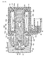
FIG. 1] FIG. 1 is a vertical sectional view of a decompression valve of Embodiment 1. (first embodiment) - [
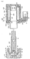
FIG. 2] FIG. 2 is an enlarged exploded vertical sectional view of an electromagnetic cut-off valve. (first embodiment) - [
FIG. 3] FIG. 3 is an enlarged view of the part shown byarrow 3 inFIG. 2 . (first embodiment) - [
FIG. 4] FIG. 4 is a sectional view, corresponding toFIG. 3 , of Embodiment 2. (second embodiment) - [
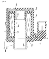
FIG. 5] FIG. 5 is a vertical sectional view of an electromagnetic cut-off valve ofEmbodiment 3. (third embodiment) - [
FIG. 6] FIG. 6 is an exploded vertical sectional view of the electromagnetic cut-off valve ofFIG. 5 . (third embodiment) - [
FIG. 7] FIG. 7 is a vertical sectional view of a coil-side assembled unit of Embodiment 4. (fourth embodiment) - [
FIG. 8] FIG. 8 is an exploded vertical sectional view of the coil-side assembled unit ofFIG. 7 . (fourth embodiment) - [
FIG. 9] FIG. 9 is a vertical sectional view of a coil-side assembled unit of Embodiment 5. (fifth embodiment) - [
FIG. 10] FIG. 10 is a vertical sectional view of an electromagnetic cut-off valve of Embodiment 6. (sixth embodiment) -
- 13 Body
- 43A, 43B, 43C Bobbin
- 44 Coil
- 45A, 45B, 45C Guide tube
- 46A, 46B Fixed core
- 47 Plunger
- 48A, 48B Magnetic frame
- 49A, 49B, 49C, 49D Cover portion
- 50 Coupler part
- 58, 89 Threaded hole
- 63, 85, 96, 123 Male thread
- 69A, 69B, 69C, 69D Coil-side assembled unit
- 70, 110, 111, 112, 113 Labyrinth groove
- 84, 95 Holder
- 90 Annular step
- 94 Flange part
- 98 Annular gap
- 103, 104 Magnetic frame member
- 103b Magnetic flux transfer portion
- 116 Coil assembly
- 124 Annular recess
- Modes for carrying out the present invention are explained below by reference to the attached drawings.
- Embodiment 1 of the present invention is explained by reference to
FIG. 1 to FIG. 3 ; first, inFIG. 1 , this decompression valve for a gas is for decompressing compressed natural gas and supplying it to an engine (not illustrated) and includes abody 13 that has in a central part a vertically extendinghousing hole 12 having in an intermediate part an inward collar 11 protruding in a radially inward direction, and adiaphragm cover 14 that is formed by press forming thin metal and is joined to thebody 13, thebody 13 housing avalve mechanism 15 and being provided with arelief valve 16 and an electromagnetic cut-offvalve 17A, which is a solenoid device. - The
valve mechanism 15 is housed in thehousing hole 12 beneath the inward collar 11 so that it is driven by adiaphragm 18, and has aguide member 20 that is made of metal and gas-tightly fitted into thehousing hole 12, avalve seat member 21 that liquid-tightly abuts against the inward collar 11 from below and is joined to theguide member 20 while forming avalve chamber 22 between itself and theguide member 20 and that is provided with avalve seat 24 having avalve hole 23 in its central part and facing thevalve chamber 22, avalve shaft 25 that is slidably fitted into theguide member 20 while loosely extending through thevalve hole 23, and avalve body 26 that is made of a synthetic resin and fitted around the outer periphery of thevalve shaft 25 within thevalve chamber 22 so that it can be seated on thevalve seat 24. - An annular high-
pressure chamber 28 is formed between theguide member 20 andvalve seat member 21 and thebody 13, the high-pressure chamber 28 communicating with thevalve chamber 22 via afilter 27 held between theguide member 20 and thevalve seat member 21, adecompression chamber 29 communicating with thevalve hole 23 is formed in an upper part of thebody 13, and thevalve mechanism 15 is housed in thehousing hole 12 so as to be disposed between the high-pressure chamber 28 and thedecompression chamber 29. - Screwed into the
housing hole 12 is a ring-shaped retainingmember 30 that abuts against theguide member 20 from below so as to hold theguide member 20 and thevalve seat member 21 between itself and the inward collar 11, and by screwing this retainingmember 30 into thehousing hole 12 thevalve mechanism 15 is fixedly housed within thehousing hole 12. - An
adjustment member 31 is gas-tightly screwed into thehousing hole 12 at a position spaced downwardly from the retainingmember 30, theadjustment member 31 being capable of changing its back and forth position along the axial direction. Furthermore, one end part of thevalve shaft 25 gas-tightly and slidably extends through theguide member 20, and aback coil spring 33 is provided in a compressed state between theadjustment member 31 and a spring-bearingmember 32 fitted on the one end of thevalve shaft 25. Adjusting the back and forth position in the axial direction of theadjustment member 31 by rotating theadjustment member 31 enables the spring load of theback coil spring 33 to be adjusted. - A
back pressure chamber 34 is formed between theadjustment member 31 and thebody 13 and guidemember 20, the one end part of thevalve shaft 25 extending to theback pressure chamber 34, and apassage groove 35 is provided on the outer periphery of thevalve shaft 25, thepassage groove 35 providing communication between theback pressure chamber 34 and thedecompression chamber 29. - A linking
member 36 is gas-tightly and slidably fitted into an upper part of thehousing hole 12, the other end part of thevalve shaft 25 being linked to the linkingmember 36, and the linkingmember 36 is linked to a central part of thediaphragm 18, whose peripheral edge part is held between the upper part of thebody 13 and thediaphragm cover 14. - A
pressure action chamber 38 communicating with thedecompression chamber 29 via a throughpassage 37 provided in thebody 13 is formed between thediaphragm 18 and thebody 13, one face of thediaphragm 18 facing thepressure action chamber 38, and aspring chamber 39 is formed between thediaphragm 18 and thediaphragm cover 14, the other face of thediaphragm 18 facing thespring chamber 39. Moreover, a coil-shapeddiaphragm spring 40 housed in thespring chamber 39 is provided in a compressed state between thediaphragm cover 14 and thediaphragm 18. Furthermore, a negative-pressure introducing pipe 41 communicating with thespring chamber 39 is connected to thediaphragm cover 14, this negative-pressure introducing pipe 41 is connected to an engine, and intake negative pressure of the engine is introduced into thespring chamber 39. - In such a
valve mechanism 15, when thediaphragm 18 flexes toward thespring chamber 39 side against the spring force of thediaphragm spring 40 due to the pressure of thepressure action chamber 38, thevalve mechanism 15 closes, and when thediaphragm 18 flexes toward thepressure action chamber 38 side due to a decrease in the pressure of thepressure action chamber 38, thevalve mechanism 15 opens; repeating such opening and closing of thevalve mechanism 15 allows high pressure compressed natural gas from the high-pressure chamber 28 to be decompressed and guided to thedecompression chamber 29. - An outlet passage (not illustrated) communicating with the
decompression chamber 29 is provided in thebody 13. Furthermore, therelief valve 16 is opened when the pressure of thedecompression chamber 29 exceeds a predetermined pressure to thus release part of the pressure to the outside, and is disposed on thebody 13 so as to be connected to thedecompression chamber 29. - The electromagnetic cut-off
valve 17A includes abobbin 43A that is formed from a synthetic resin, acoil 44 that is wound around thebobbin 43A, aguide tube 45A that is made of a non-magnetic material, has one end part fixed to thebody 13, and is inserted into thebobbin 43A, a fixedcore 46A that blocks the other end of theguide tube 45A and is secured to theguide tube 45A, aplunger 47 that opposes the fixedcore 46A and is slidably fitted into theguide tube 45A, amagnetic frame 48A that is made of a magnetic metal, covers at least thebobbin 43A and thecoil 44, and provides a magnetic connection between the fixedcore 46A and theplunger 47, acover portion 49A that is made of a synthetic resin, covers thebobbin 43A and thecoil 44, and integrally has acoupler part 50 projecting outwardly from themagnetic frame 48A, areturn spring 51 provided between the fixedcore 46A and theplunger 47, and avalve member 52 retained on theplunger 47 on the side opposite to the fixedcore 46A. - Referring in addition to
FIG. 2 andFIG. 3 , coaxially provided in thebody 13 are acommunication hole 53 that has its inner end communicating with the high-pressure chamber 28, a main valve chamber-forminghole 54 that has a larger diameter than thecommunication hole 53 and communicates with the outer end of thecommunication hole 53, an annularinclined face 55 that, while increasing in diameter in going outward in the axial direction, is connected to the outer end of the main valve chamber-forminghole 54, anannular step 56 that is connected to the outer end of the annularinclined face 55 and faces outward in the axial direction, afitting hole 57 that extends from the outer periphery of theannular step 56 outwardly in the axial direction, and a threadedhole 58 that has a larger diameter than thefitting hole 57 and is connected to the outer end of thefitting hole 57. - Referring in addition to
FIG. 3 , provided on the one end part of theguide tube 45A are a small diametercylindrical part 60 that has anannular seal member 59 disposed between itself and the annularinclined face 55, a fittingtubular part 61 that is formed so as to have a larger diameter than the small diametercylindrical part 60 so as to be fitted into thefitting hole 57 and abut against theannular step 56, a screw-intubular part 62 that is formed so as to have a larger diameter than the fittingtubular part 61 and has amale thread 63 cut on the outer periphery, themale thread 63 being screwed into the threadedhole 58, and atool engagement portion 64 that has a non-circular cross section and with which a tool is engaged so as to rotate theguide tube 45A, the one end part of theguide tube 45A being fixed to thebody 13 by screwing themale thread 63 on the outer periphery into the threadedhole 58. - The
magnetic frame 48A is formed from a firstmagnetic frame member 65 that covers one end, in the axial direction, of thebobbin 43A and the outer periphery of thecoil 44, and a secondmagnetic frame member 66 that covers the other end, in the axial direction, of thebobbin 43A. - The first
magnetic frame member 65 integrally has a ring plate-shaped firstend plate portion 65a that abuts against an outer face of the one end in the axial direction of thebobbin 43A, a cylindrical magneticflux transfer portion 65b that is connected to the inner periphery of the firstend plate portion 65a and surrounds part of the outer periphery of theguide tube 45A, and a cylindricalouter frame portion 65c that has one end connected to the outer periphery of the firstend plate portion 65a and covers thebobbin 43A and the outer periphery of thecoil 44, and theouter frame portion 65c is provided with a cutout part for thecoupler part 50 to project outwardly from theouter frame portion 65c, thecoupler part 50 being formed integrally with thecover portion 49A while makingterminal plates 67 extending outwardly from the one end of thebobbin 43A extend to thecoupler part 50. - The second
magnetic frame member 66 is formed so as to integrally have a ring plate-shaped secondend plate portion 66a that abuts against the other end of thebobbin 43A and afitting projection 66b that is projectingly provided in the center of the secondend plate portion 66a so as to be fitted into the other end part of thebobbin 43A, thefitting projection 66b being provided with afitting recess 68. - The other end of the
outer frame portion 65c of the firstmagnetic frame member 65 is joined by swaging to the outer periphery of the secondend plate portion 66a of the secondmagnetic frame member 66, but since thecover portion 49A makes the first and secondmagnetic frame members magnetic frame members - The fixed
core 46A is formed from a magnetic metal into a rod shape having a circular cross section, and is secured to theguide tube 45A by welding, etc. in a state in which one end part thereof is fitted into the other end part of theguide tube 45A while the outer end thereof projects from the other end of theguide tube 45A, and the other end part of this fixedcore 46A is fitted into thefitting recess 68. - The
bobbin 43A, thecoil 44 wound around thebobbin 43A, themagnetic frame 48A, and thecover portion 49A form a coil-side assembledunit 69A by assembling these 43A, 44, 48A, and 49A in advance, and this coil-side assembledunit 69A is fixed to theguide tube 45A. - Moreover, the
cover portion 49A is formed so as to cover thebobbin 43A and thecoil 44 and also cover that portion of themagnetic frame 48A that covers thebobbin 43A and thecoil 44, and in Embodiment 1 the coil-side assembledunit 69A is formed by covering thebobbin 43A, thecoil 44, and themagnetic frame 48A with thecover portion 49A except for part of the magneticflux transfer portion 65b. - The coil-side assembled
unit 69A is fixed to theguide tube 45A by press fitting theguide tube 45A fixed to thebody 13 into the magneticflux transfer portion 65b of themagnetic frame 48A. - Furthermore, of the first
magnetic frame member 65 of themagnetic frame 48A, part of the magneticflux transfer portion 65b protrudes from thecover portion 49A; in order to inhibit water that has infiltrated via a gap formed between thecover portion 49A and the outer periphery of the magneticflux transfer portion 65b from flowing toward thecoil 44 wound around thebobbin 43A, a plurality ofannular labyrinth grooves 70 are provided on a face, that faces thecover portion 49A, of the firstend plate portion 65a of the firstmagnetic frame member 65. - Due to the
guide tube 45A being fixed to thebody 13 in a state in which the one end part thereof is inserted into the main valve chamber-forminghole 54 and theplunger 47 being slidably fitted into theguide tube 45A, amain valve chamber 71 is formed between thebody 13 and one end of theguide tube 45A andplunger 47. Moreover, thebody 13 is provided with aninlet passage 72 communicating with themain valve chamber 71, high pressure gas being introduced into themain valve chamber 71. - The
body 13 is also provided with anannular valve seat 73 projecting slightly toward themain valve chamber 71 side so as to surround an end, opening to themain valve chamber 71, of thecommunication hole 53 communicating with the high-pressure chamber 28. - The
valve member 52 is formed by integrally connecting amain valve portion 52a on one end side and apilot valve portion 52b on the other end side via a linkingtubular part 52c that forms a step between thevalve portions main valve portion 52a being formed into a disc shape movably housed in the main valve chamber-forminghole 54, thepilot valve portion 52b being formed into a disc shape having as one end face a taperedface 74 having a diameter that decreases in going toward theplunger 47 side, and the diameter of thepilot valve portion 52b being set smaller than the diameter of themain valve portion 52a. Coaxially provided in a central part of thevalve member 52 are afirst passage 75 always communicating with thecommunication hole 53 and asecond passage 76 communicating with thefirst passage 75 and opening in a central part on the one end face of thepilot valve portion 52b, thesecond passage 76 being formed with a smaller diameter than that of thefirst passage 75. - An end part of the
plunger 47 that faces themain valve chamber 71 is provided with arecess 77 for thepilot valve portion 52b to be inserted into, thepilot valve portion 52b is loosely inserted into therecess 77 so as to be prevented from escaping from therecess 77 by means of a C-shapedretaining ring 78 fixed to the other end of theplunger 47, and apilot valve chamber 79 communicating with themain valve chamber 71 is formed between thepilot valve portion 52b and theplunger 47. Furthermore, arubber seal 80 that blocks an opening of thesecond passage 76 to thepilot valve chamber 79 when the central part of the end face of thepilot valve portion 52b is seated is embedded in a central part of a closed end of therecess 77. The retainingring 78 is thus fixed to theplunger 47 at a position at which thepilot valve portion 52b can move in the axial direction relative to theplunger 47 between the retainingring 78 and the closed end of therecess 77. - Also embedded in the
main valve portion 52a is anannular rubber seal 81 that blocks communication between themain valve chamber 71 and thecommunication hole 53 by being seated on thevalve seat 73. - In such an electromagnetic cut-off
valve 17A, when the engine is stopped, due to de-energization of thecoil 44 theplunger 47 is moved in a direction away from the fixedcore 46A by means of the spring force of thereturn spring 51, therubber seal 81 of themain valve portion 52a is seated on thevalve seat 73 to thus block communication between themain valve chamber 71 and thecommunication hole 53, and at the same time thepilot valve portion 52b is seated on therubber seal 80 to thus block communication between thepilot valve chamber 79 and thecommunication hole 53, thereby stopping the supply of high pressure gas toward the high-pressure chamber 28 side. - On the other hand, when the engine starts running and the
coil 44 is energized, first theplunger 47 moves toward the fixedcore 46A side only by an amount that detaches thepilot valve portion 52b from therubber seal 80, and thesecond passage 76 communicating with thecommunication hole 53 via thefirst passage 75 communicates with thepilot valve chamber 79. This allows high pressure gas to gradually flow from themain valve chamber 71 to thecommunication hole 53 via thepilot valve chamber 79, thesecond passage 76, and thefirst passage 75, thereby making the difference between the pressure acting on themain valve portion 52a from themain valve chamber 71 side and that from thecommunication hole 53 side small. When the electromagnetic force due to thecoil 44 overcomes the difference in pressure acting on themain valve portion 52a, theplunger 47 moves further toward the fixedcore 46A side, therubber seal 81 of themain valve portion 52a detaches from thevalve seat 73, and high pressure gas flows from themain valve chamber 71 to thecommunication hole 53. - The operation of Embodiment 1 is now explained. The
guide tube 45A is fixed to thebody 13 by screwing into the threadedhole 58 provided in thebody 13 themale thread 63 provided on the outer periphery of the one end part of theguide tube 45A, and the coil-side assembledunit 69A formed by assembling in advance thebobbin 43A, thecoil 44, themagnetic frame 48A, and thecover portion 49A is fixed to theguide tube 45A by press fitting theguide tube 45A into the magneticflux transfer portion 65b of themagnetic frame 48A; it is therefore unnecessary to employ a special component for fixing or to carry out special machining when assembling onto theguide tube 45A thebobbin 43A, thecoil 44, thecover portion 49A integrally having thecoupler part 50, and themagnetic frame 48A, and it becomes possible to carry out assembly with enhanced workability by means of a structure having fewer components and low cost. Furthermore, the position of thecoupler part 50 in the peripheral direction of theguide tube 45A can be set freely and easily only by determining it when press fitting theguide tube 45A into the magneticflux transfer portion 65b of themagnetic frame 48A, and the position of thecoupler part 50 will not deviate from the set position. - Furthermore, since the
cover portion 49A of the coil-side assembledunit 69A is formed so as to cover thebobbin 43A and thecoil 44 and also cover that portion of themagnetic frame 48A that covers thebobbin 43A and thecoil 44, the mass productivity of the coil-side assembledunit 69A can be enhanced by making thebobbin 43A, thecoil 44, themagnetic frame 48A, and thecover portion 49A into a unit, and since that portion of themagnetic frame 48A that covers thebobbin 43A and thecoil 44 is covered by thecover portion 49A, it is possible to make themagnetic frame 48A resistant to rusting. - Moreover, part of the magnetic
flux transfer portion 65b of the firstmagnetic frame member 65 of themagnetic frame 48A projects from thecover portion 49A; since the plurality ofannular labyrinth grooves 70 are provided on the face, facing thecover portion 49A, of the firstend plate portion 65a of the firstmagnetic frame member 65, it is possible for thelabyrinth grooves 70 to inhibit water that has infiltrated through the gap formed between thecover portion 49A and the outer periphery of the magneticflux transfer portion 65b from flowing toward thecoil 44 wound around thebobbin 43A, and it becomes unnecessary for a seal member to be disposed between the firstend plate portion 65a and thecover portion 49A, thereby contributing to a reduction in the number of components. - Embodiment 1 above has a structure in which the coil-side assembled
unit 69A is fixed to theguide tube 45A by press fitting theguide tube 45A into the magneticflux transfer portion 65b of themagnetic frame 48A, but it can have a structure in which the coil-side assembledunit 69A is fixed to theguide tube 45A by press fitting thefixed core 46A fixed to theguide tube 45A into thefitting recess 68 provided in thefitting projection 66b of the secondmagnetic frame member 66 of themagnetic frame 48A. - Embodiment 2 of the present invention is explained by reference to
FIG. 4 ; parts corresponding to those of Embodiment 1 are denoted by the same reference numerals and symbols and are only illustrated, detailed explanation thereof being omitted. - A
flange part 83 is provided integrally with one end part of aguide tube 45B, theflange part 83 protruding radially outwardly so as to abut against theannular step 56 while being fitted into afitting hole 57 provided in thebody 13, amale thread 85, which is screwed into the threadedhole 58, is cut on the outer periphery of acylindrical holder 84 surrounding the one end part of theguide tube 45B, and atool engagement portion 84a having a non-circular cross section and having a tool engaged therewith for rotating theholder 84 is provided on the outer end of theholder 84. - By screwing the
male thread 85 of theholder 84 holding theflange part 83 between itself and theannular step 56 into the threadedhole 58 and tightening, theguide tube 45B is fixed to thebody 13. - In accordance with Embodiment 2 also, the same effects as those of Embodiment 1 above can be exhibited.
-
Embodiment 3 of the present invention is explained by reference toFIG. 5 andFIG. 6 ; parts corresponding to those of Embodiment 1 are denoted by the same reference numerals and symbols and are only illustrated, detailed explanation thereof being omitted. - First, in
FIG. 5 , an electromagnetic cut-offvalve 17B includes abobbin 43B made of a synthetic resin, acoil 44 wound around thebobbin 43B, aguide tube 45C made of a non-magnetic material and having one end part fixed to abody 13 and inserted into thebobbin 43B, a fixedcore 46B fixed to theguide tube 45C so as to block the other end of theguide tube 45C, aplunger 47 slidably fitted into theguide tube 45C so as to oppose the fixedcore 46B, amagnetic frame 48B made of a magnetic metal and covering at least thebobbin 43B and thecoil 44 so as to provide a magnetic connection between the fixedcore 46B and theplunger 47, acover portion 49B made of a synthetic resin, covering thebobbin 43B and thecoil 44, and integrally having acoupler part 50 projecting outwardly from themagnetic frame 48B, areturn spring 51 provided between the fixedcore 46B and theplunger 47, and avalve member 52 retained on theplunger 47 on the side opposite to the fixedcore 46B. - Referring in addition to
FIG. 6 , coaxially provided in thebody 13 are acommunication hole 53 having its inner end communicating with the high-pressure chamber 28 (see Embodiment 1), a main valve chamber-forminghole 54 formed so as to have a larger diameter than that of thecommunication hole 53 and communicating with the outer end of thecommunication hole 53, afitting hole 88 having a larger diameter than that of the main valve chamber-forminghole 54 and connected to the outer end of the main valve chamber-forminghole 54, and a threadedhole 89 having a larger diameter than that of thefitting hole 88 and connected to the outer end of thefitting hole 88. Furthermore, a firstannular step 90 facing outward in the axial direction is formed between the main valve chamber-forminghole 54 and thefitting hole 88, a secondannular step 91 facing outward in the axial direction is formed between thefitting hole 88 and the threadedhole 89, and aring groove 93 is provided in the firstannular step 90, anO ring 92 being fitted into thering groove 93. - A
flange part 94 is provided at one end part of theguide tube 45C so as to protrude radially outward, theflange part 94 being fitted into thefitting hole 88 so that theO ring 92 is disposed between itself and the firstannular step 90. - A
male thread 96 provided on the outer periphery of acylindrical holder 95 coaxially surrounding theguide tube 45C so as to hold theflange part 94 of theguide tube 45C between theholder 95 and the firstannular step 90 is screwed into the threadedhole 89 of thebody 13, and a bottomedtool engagement hole 97 is provided in the outer end of theholder 95, a tool used for rotating theholder 95 engaging with thetool engagement hole 97. By screwing themale thread 96 on the outer periphery of theholder 95 into the threadedhole 89 and tightening, theflange part 94 at the one end part of theguide tube 45C is held between the firstannular step 90 and theholder 95 to thus fix theguide tube 45C to thebody 13 and form anannular gap 98 between the inner periphery of theholder 95 and the outer periphery of theguide tube 45C, theannular gap 98 opening outwardly in the axial direction. - The
bobbin 43B integrally has acylindrical part 100, afirst collar 101 protruding radially outwardly from a position that is spaced inwardly from one end, in the axial direction, of thecylindrical part 100, and asecond collar 102 protruding radially outwardly from a position that is spaced inwardly from the other end, in the axial direction, of thecylindrical part 100, and thecoil 44 is wound around the outer periphery of thecylindrical part 100 between the first andsecond collars - The
magnetic frame 48B is formed by joining to each other by swaging a firstmagnetic frame member 103 and a secondmagnetic frame member 104. The firstmagnetic frame member 103 integrally has a ring plate-shaped firstend plate portion 103a that is disposed so as to be spaced outwardly in the axial direction of thefirst collar 101 of thebobbin 43B and abuts against one end, in the axial direction, of thecylindrical part 100, and a cylindrical magneticflux transfer portion 103b that is connected to the inner periphery of the firstend plate portion 103a and coaxially surrounds a part of theguide tube 45C that projects from thebobbin 43B toward thebody 13 side. - The second
magnetic frame member 104 is formed so as to integrally have a ring plate-shaped secondend plate portion 104a that is disposed so as to be spaced outwardly in the axial direction of thesecond collar 102 of thebobbin 43B and abuts against the other end, in the axial direction, of thecylindrical part 100, anouter frame portion 104b that is connected to the outer periphery of the secondend plate portion 104a, covers thebobbin 43B and thecoil 44, and extends toward the outer periphery of the firstend plate portion 103a, and a fittingtubular part 104c that is connected to the inner periphery of the secondend plate portion 104a and is fitted into the other end part of thecylindrical part 100 of thebobbin 43B. - The
outer frame portion 104b of the secondmagnetic frame member 104 is joined by swaging to the outer periphery of the firstend plate portion 103a of the firstmagnetic frame member 103, thereby joining the first and secondmagnetic frame members magnetic frame 48B. Moreover, acutout part 105 is provided in theouter frame portion 104b of the secondmagnetic frame member 104, part of thefirst collar 101 of thebobbin 43B projecting via thecutout part 105, and thecoupler part 50 is provided integrally with thecover portion 49B,terminal plates 67 extending outwardly from thefirst collar 101 going into thecoupler part 50. - The fixed
core 46B is formed from a magnetic metal into a rod shape having a circular cross section, and is secured to theguide tube 45C by welding, etc. in a state in which the inner end part thereof is fitted into the other end part of theguide tube 45C while the outer end thereof projects from the other end of theguide tube 45C, and part of this fixedcore 46B is fitted into the fittingtubular part 104c of the secondmagnetic frame member 104. - The
bobbin 43B, thecoil 44 wound around thebobbin 43B, themagnetic frame 48A, and thecover portion 49B form a coil-side assembledunit 69B by assembling these 43B, 44, 48B, and 49B in advance, and this coil-side assembledunit 69B is fixed to theguide tube 45C. - Moreover, the
cover portion 49B is formed so as to cover thebobbin 43B and thecoil 44 and also cover that portion of themagnetic frame 48B that covers thebobbin 43B and thecoil 44, and inEmbodiment 3 the coil-side assembledunit 69B is formed by covering thebobbin 43B, thecoil 44, and themagnetic frame 48B with thecover portion 49B except for part of the magneticflux transfer portion 103b. - The
cover portion 49B is formed so as to fill a section between thefirst collar 101 of thebobbin 43B and the firstend plate portion 103a of the firstmagnetic frame member 103 and a section between thesecond collar 102 of thebobbin 43B and the secondend plate portion 104a of the secondmagnetic frame member 104, and a throughhole 106 is provided in the secondend plate portion 104a, the throughhole 106 guiding molten resin into the section between thesecond collar 102 and the secondend plate portion 104a when forming thecover portion 49B. Furthermore, in order to fixedly determine the position, in the peripheral direction, of thebobbin 43B relative to themagnetic frame 48B, apositioning pin 107 projectingly provided on thefirst collar 101 of thebobbin 43B is inserted through apositioning hole 108 provided in the firstend plate portion 103a of the firstmagnetic frame member 103 of themagnetic frame 48B. - Furthermore, of the first
magnetic frame member 103 of themagnetic frame 48B, part of the magneticflux transfer portion 103b projects from thecover portion 49B; in order to inhibit water that has infiltrated via a gap formed between thecover portion 49B and the outer periphery of the magneticflux transfer portion 103b from flowing toward thecoil 44 wound around thebobbin 43B, pluralities ofannular labyrinth grooves cover portion 49B, of the firstend plate portion 103a of the firstmagnetic frame member 103 and an outer face, that faces thecover portion 49B, of thefirst collar 101 of thebobbin 43B. - Moreover, a
hole 114 is formed in thecover portion 49B so that part of the secondend plate portion 104a of the secondmagnetic frame member 104 of themagnetic frame 48B faces the exterior when pulling out the positioning pin for carrying out positioning of themagnetic frame 48B and thebobbin 43B wound around thecoil 44 when carrying out molding; in order to inhibit water that has infiltrated via thehole 114 from flowing toward thecoil 44 wound around thebobbin 43A, pluralities ofannular labyrinth grooves cover portion 49B, of the secondend plate portion 104a of the secondmagnetic frame member 104 and an outer face, facing thecover portion 49B, of thesecond collar 102 of thebobbin 43B. - The coil-side assembled
unit 69B thus formed is fixed to theguide tube 45C by press fitting the cylindrical magneticflux transfer portion 103b, which, while forming part of themagnetic frame 48B, coaxially surrounds a portion of theguide tube 45C that projects from thebobbin 43B toward thebody 13 side, into the inner periphery of theholder 95 within theannular gap 98, which is formed between theholder 95 and theguide tube 45C. - In accordance with
Embodiment 3, theguide tube 45C and theholder 95 forming theannular gap 98 between itself and theguide tube 45C are fixed to thebody 13 by screwing into the threadedhole 89 of thebody 13 themale thread 96 on the outer periphery of thecylindrical holder 95 holding theguide tube 45C between itself and thebody 13, and the coil-side assembledunit 69B formed by assembling in advance thebobbin 43B, thecoil 44, themagnetic frame 48B, and thecover portion 49B is fixed to theguide tube 45C by press fitting the cylindrical magneticflux transfer portion 103b forming part of themagnetic frame 48B into the inner periphery of theholder 95 within theannular gap 98; it is therefore unnecessary to employ a special component for fixing or to carry out special machining when assembling thebobbin 43B, thecoil 44, thecover portion 49B integrally having thecoupler part 50, and themagnetic frame 48B onto theguide tube 45C, and it becomes possible to carry out assembly with enhanced workability by means of a structure having fewer components and low cost. Furthermore, the position of thecoupler part 50 in the peripheral direction of theguide tube 45C can be set freely and easily only by determining it when press fitting the magneticflux transfer portion 103b into the inner periphery of theholder 95, and the position of thecoupler part 50 will not deviate from the set position. - Moreover, providing the magnetic
flux transfer portion 103b enables the area of the magnetic path between themagnetic frame 48B and theplunger 47 to be increased, thereby increasing the attractive force of the fixedcore 46B acting on theplunger 47. Furthermore, since the magneticflux transfer portion 103b is inserted into theannular gap 98, any increase in the axial length of the electromagnetic cut-offvalve 17B due to the magneticflux transfer portion 103b being provided on themagnetic frame 48B can be suppressed; moreover, it is unnecessary to take into consideration deformation of the guide tube, into which theplunger 47 is fitted, due to the magneticflux transfer portion 103b being press fitted into the inner periphery of theholder 95, and the slide gap between theguide tube 45C and theplunger 47 can be set small. - Furthermore, since the
flange part 94 integrally provided with the end part, on thebody 13 side, of theguide tube 45C and protruding in the radially outward direction is held between theannular step 90 of thebody 13 and theholder 95, it is possible to easily form theannular gap 98 between theholder 95 and the guide tube 45. - Moreover, since the
cover portion 49B of the coil-side assembledunit 69B is formed so as to cover thebobbin 43B and thecoil 44 and also cover that portion of themagnetic frame 48B that covers thebobbin 43B and thecoil 44, the mass productivity of the coil-side assembledunit 69B can be enhanced by making thebobbin 43B, thecoil 44, themagnetic frame 48B, and thecover portion 49B into a unit, and since that portion of themagnetic frame 48B that covers thebobbin 43B and thecoil 44 is covered by thecover portion 49B, it is possible to make themagnetic frame 48B resistant to rusting. - Moreover, part of the magnetic
flux transfer portion 103b of the firstmagnetic frame member 103 of themagnetic frame 48B projects from thecover portion 49B; since the pluralities ofannular labyrinth grooves cover portion 49B, of the firstend plate portion 103a of the firstmagnetic frame member 103 and the outer face, facing thecover portion 49B, of thefirst collar 101 of thebobbin 43B, it is possible to inhibit water that has infiltrated through the gap formed between thecover portion 49B and the outer periphery of the magneticflux transfer portion 103b from flowing toward thecoil 44 wound around thebobbin 43B, and it becomes unnecessary for a seal member to be disposed between the firstend plate portion 103a and thecover portion 49B and between thefirst collar 101 and thecover portion 49B, thereby contributing to a reduction in the number of components. - Furthermore, the
hole 114, which is formed by pulling out the positioning pin, is formed in thecover portion 49B so that part of the secondend plate portion 104a of the secondmagnetic frame member 104 faces the exterior; since the pluralities ofannular labyrinth grooves cover portion 49B, of the secondend plate portion 104a of the secondmagnetic frame member 104 and the outer face, facing thecover portion 49B, of thesecond collar 102 of thebobbin 43B, water that has infiltrated via thehole 114 can be inhibited from flowing toward thecoil 44 wound around thebobbin 43B, and it is unnecessary for a seal member to be disposed between the secondend plate portion 104a and thecover portion 49B and between thesecond collar 102 and thecover portion 49B, thus contributing to a reduction in the number of components. - As another embodiment of the present invention, a coil-side assembled
unit 69B may be fixed to aguide tube 45C by press fitting aguide tube 45C or a fixedcore 46B secured to theguide tube 45C into amagnetic frame 48B while inserting a cylindrical magneticflux transfer portion 103b forming part of themagnetic frame 48B into anannular gap 98. - Embodiment 4 of the present invention is explained by reference to
FIG. 7 andFIG. 8 ; parts corresponding to those ofEmbodiment 3 explained by reference toFIG. 5 andFIG. 6 are denoted by the same reference numerals and symbols and are only illustrated, detailed explanation thereof being omitted. - First, in
FIG. 7 , this coil-side assembledunit 69C is used in place of the coil-side assembledunit 69B ofEmbodiment 3, and is formed from abobbin 43B, acoil 44 wound around thebobbin 43B, amagnetic frame 48B, and acover portion 49C. - Referring in addition to
FIG. 8 , thebobbin 43B, thecoil 44 wound around thebobbin 43B, and thecover portion 49C covering thebobbin 43B and thecoil 44 form acoil assembly 116, and thecover portion 49C is provided integrally with acoupler part 50. - The
magnetic frame 48B is the same as themagnetic frame 48B ofEmbodiment 3 and is formed by joining to each other first and secondmagnetic frame members coil assembly 116 in cooperation, the first and secondmagnetic frame members - In accordance with Embodiment 4, since the coil-side assembled
unit 69C is formed by covering thecoil assembly 116, which is formed by covering thebobbin 43B and thecoil 44 by thecover portion 49C, with the first and secondmagnetic frame members magnetic frame members magnetic frame 48B, compared with an arrangement in which part of themagnetic frames cover portions cover portion 49C can have a simple structure. - In Embodiment 4 above, the
magnetic frame 48B is formed from two magnetic frame members, that is, the first and secondmagnetic frame members coil assembly 116 in cooperation. - Embodiment 5 of the present invention is explained by reference to
FIG. 9 ; parts corresponding to those of each of the above-mentioned embodiments are denoted by the same reference numerals and symbols and are only illustrated, detailed explanation thereof being omitted. - This coil-side assembled
unit 69D is used in place of the coil-side assembledunit 69B ofEmbodiment 3, and is formed from abobbin 43C, acoil 44 wound around thebobbin 43C, amagnetic frame 48B, and acover portion 49D. - The
bobbin 43C integrally has a cylindrical part 117, afirst collar 118 protruding radially outwardly from a position that is spaced inwardly from one end, in the axial direction, of the cylindrical part 117, and asecond collar 119 protruding radially outwardly from a position that is spaced inwardly from the other end, in the axial direction, of the cylindrical part 117, and thecoil 44 is wound around the outer periphery of the cylindrical part 117 between the first andsecond collars - The
magnetic frame 48B is the same as themagnetic frame 48B ofEmbodiment 3 and Embodiment 4, and is formed by joining to each other first and secondmagnetic frame members bobbin 43C is set larger than the internal diameter of a magneticflux transfer portion 103b of themagnetic frame 48B and the external diameter of a fittingtubular part 104c. - The entirety of the
bobbin 43C and thecoil 44 wound around thebobbin 43C is thus covered by thecover portion 49D, and acylindrical part 120 is formed on thecover portion 49D, thecylindrical part 120 covering the inner periphery of the cylindrical part 117 of thebobbin 43C and forming an inner periphery that is flush with the inner periphery of the magneticflux transfer portion 103b of themagnetic frame 48B. - In accordance with Embodiment 5, since the entirety of the
bobbin 43C and thecoil 44 is covered by thecover portion 49D, it is possible to reliably inhibit water from infiltrating into thecoil 44 side without a seal member such as an O ring being disposed between thebobbin 43C and thecover portion 49D. - Embodiment 6 of the present invention is explained by reference to
FIG. 10 ; parts corresponding to those of each of the above-mentioned embodiments are denoted by the same reference numerals and symbols and are only illustrated, detailed explanation thereof being omitted. - Coaxially provided in the
body 13 are acommunication hole 53 having its inner end communicating with a high-pressure chamber 28 (see Embodiment 1), a main valve chamber-forminghole 54 having a larger diameter than that of thecommunication hole 53 and being connected to the outer end of thecommunication hole 53, and a threadedhole 89 having a larger diameter than that of the main valve chamber-forminghole 54 and being connected to the outer end of the main valve chamber-forminghole 54. Furthermore, anannular step 122 facing outward in the axial direction is formed between the main valve chamber-forminghole 54 and the threadedhole 89, and aring groove 93 is provided in theannular step 122, anO ring 92 being fitted into thering groove 93. - A
guide tube 45D is formed so as to have in one end part an annular recess 124 that is coaxially disposed radially inward of the threadedhole 89 and opens outwardly in the axial direction, and a fixedcore 46B is secured to the other end of theguide tube 45D. Moreover, amale thread 123 is cut on the outer periphery of the one end part of theguide tube 45D, and a bottomedtool engagement hole 125 is provided in a portion of the one end part of theguide tube 45D that faces outward in the axial direction, a tool for rotating theguide tube 45D engaging with thetool engagement hole 125. By screwing themale thread 123 into the threadedhole 89 and tightening it until theguide tube 45D abuts against theO ring 92, theguide tube 45D is fixed to thebody 13. - A coil-side assembled
unit 69B is fixed to theguide tube 45D by press fitting, into theguide tube 45D within the annular recess 124, the outer periphery of a cylindrical magneticflux transfer portion 103b coaxially surrounding a portion of theguide tube 45D that projects from thebobbin 43B toward thebody 13 side and forming part of themagnetic frame 48B. - In accordance with Embodiment 6 also, in the same manner as in
Embodiment 3, providing the magneticflux transfer portion 103b enables the area of the magnetic path between amagnetic frame 48B and aplunger 47 to be increased, thus increasing the attractive force of the fixedcore 46B acting on theplunger 47, and since the magneticflux transfer portion 103b is inserted into the annular recess 124, any increase in the axial length of the electromagnetic cut-off valve caused by providing the magneticflux transfer portion 103b on themagnetic frame 48B can be suppressed. - As another embodiment of the present invention, the coil-side assembled
unit 69B may be fixed to theguide tube 45D by press fitting theguide tube 45D or the fixedcore 46B fixed to theguide tube 45D into themagnetic frame 48B while inserting the magneticflux transfer portion 103b into the annular recess 124. - Modes for carrying out the present invention are explained above, but the present invention is not limited to the above-mentioned embodiments and may be modified in a variety of ways as long as the modifications do not depart from the spirit and scope thereof.
Claims (8)
- A solenoid device comprising a bobbin (43A), a coil (44) that is wound around the bobbin (43A), a guide tube (45A, 45B) that is made of a non-magnetic material, has one end part fixed to a body (13), and is inserted into the bobbin (43A), a fixed core (46A) that is fixed to the guide tube (45A, 45B) so as to block the other end of the guide tube (45A, 45B), a plunger (47) that is slidably fitted into the guide tube (45A, 45B) so as to oppose the fixed core (46A), a magnetic frame (48A) that covers at least the bobbin (43A) and the coil (44) and provides a magnetic connection between the fixed core (46A) and the plunger (47), and a cover portion (49A) that is made of a synthetic resin, covers the bobbin (43A) and the coil (44), and integrally has a coupler part (50) projecting outwardly from the magnetic frame (48A), characterized in that a male thread (63) provided on an outer periphery of the guide tube (45A) or a male thread (85) provided on an outer periphery of a cylindrical holder (84) holding the guide tube (45B) between the holder and the body (13) is screwed into a threaded hole (58) provided in the body (13) so as to fix the guide tube (45A, 45B) to the body (13), and a coil-side assembled unit (69A) formed by assembling in advance the bobbin (43A), the coil (44), the magnetic frame (48A) and the cover portion (49A) is fixed to the guide tube (45A, 45B) by press fitting the guide tube (45A, 45B) or the fixed core (46A) fixed to the guide tube (45A, 45B) into the magnetic frame (48A).
- A solenoid device comprising a bobbin (43B, 43C), a coil (44) that is wound around the bobbin (43B, 43C), a guide tube (45C, 45D) that is made of a non-magnetic material, has one end part fixed to a body (13), and is inserted into the bobbin (43B, 43C), a fixed core (46B) that is fixed to the guide tube (45C, 45D) so as to block the other end of the guide tube (45C, 45D), a plunger (47) that is slidably fitted into the guide tube (45C, 45D) so as to oppose the fixed core (46B), a magnetic frame (48B) that covers at least the bobbin (43B, 43C) and the coil (44) and provides a magnetic connection between the fixed core (46B) and the plunger (47), and a cover portion (49B, 49C, 49D) that is made of a synthetic resin, covers the bobbin (43B, 43C) and the coil (44), and integrally has a coupler part (50) projecting outwardly from the magnetic frame (48B), characterized in that a threaded hole (89) is provided in the body (13), a male thread (96) provided on an outer periphery of a cylindrical holder (95) holding the guide tube (45C) between the holder and the body (13) while forming between the holder and an outer periphery of the guide tube (45C) an annular gap (98) opening outwardly in an axial direction or a male thread (123) provided on an outer periphery of the guide tube (45D) having an annular recess (124) coaxially disposed in a radially inward direction of the threaded hole (89) and opening outwardly in an axial direction is screwed into the threaded hole (89) so as to fix the guide tube (45C, 45D) to the body (13), and a coil-side assembled unit (69B, 69C, 69D) formed by assembling in advance the bobbin (43B, 43C), the coil (44), the magnetic frame (48B) and the cover portion (49B, 49C, 49D) is fixed to the guide tube (45C, 45D) by press fitting an outer periphery of a cylindrical magnetic flux transfer portion (103b) forming part of the magnetic frame (48B) while coaxially surrounding part of the guide tube (45C, 45D) that projects from the bobbin (43B) toward the body (13) into an inner periphery of the holder (95) within the annular gap (98) or press fitting the outer periphery of the magnetic flux transfer portion (103b) into the guide tube (45D) within the annular recess (124).
- A solenoid device comprising a bobbin (43B, 43C), a coil (44) that is wound around the bobbin (43B, 43C), a guide tube (45C, 45D) that is made of a non-magnetic material, has one end part fixed to a body (13), and is inserted into the bobbin (43B, 43C), a fixed core (46B) that is fixed to the guide tube (45C, 45D) so as to block the other end of the guide tube (45C, 45D), a plunger (47) that is slidably fitted into the guide tube (45C, 45D) so as to oppose the fixed core (46B), a magnetic frame (48B) that covers at least the bobbin (43B, 43C) and the coil (44) and provides a magnetic connection between the fixed core (46B) and the plunger (47), and a cover portion (49B, 49C, 49D) that is made of a synthetic resin, covers the bobbin (43B, 43C) and the coil (44), and integrally has a coupler part (50) projecting outwardly from the magnetic frame (48B), characterized in that a threaded hole (89) is provided in the body (13), a male thread (96) provided on an outer periphery of a cylindrical holder (95) holding the guide tube (45C) between the holder and the body (13) while forming between the holder and an outer periphery of the guide tube (45C) an annular gap (98) opening outwardly in an axial direction or a male thread (123) provided on an outer periphery of the guide tube (45D) having an annular recess (124) coaxially disposed in a radially inward direction of the threaded hole (89) and opening outwardly in an axial direction is screwed into the threaded hole (89) so as to fix the guide tube (45C, 45D) to the body (13), and a coil-side assembled unit (69B, 69C, 69D) formed by assembling in advance the bobbin (43B, 43C), the coil (44), the magnetic frame (48B) and the cover portion (49B, 49C, 49D) is fixed to the guide tube (45C, 45D) by press fitting the guide tube (45C, 45D) or the fixed core (46B) fixed to the guide tube (45C, 45D) into the magnetic frame (48B) while inserting into the annular gap (98) or the annular recess (124) a cylindrical magnetic flux transfer portion (103b) forming part of the magnetic frame (48B) while coaxially surrounding part of the guide tube (45C, 45D) that projects from the bobbin (43B) toward the body (13).
- The solenoid device according to Claim 2 or 3, wherein an annular step (90) that is disposed further inward in the axial direction than the threaded hole (89) is provided on the body (13) so as to face outward in the axial direction, and a flange part (94) sandwiched between the annular step (90) and the holder (95) is integrally provided with an end part, on the body (13) side, of the guide tube (45C) so as to protrude outwardly in the radial direction.
- The solenoid device according to any one of Claims 1 to 4, wherein the cover portion (49A, 49B, 49C) of the coil-side assembled unit (69A, 69B, 69D) is formed so as to cover the bobbin (43A, 43B) and the coil (44) and also covers that part of the magnetic frame (48A, 48B) that covers the bobbin (43A, 43B, 43C) and the coil (44).
- The solenoid device according to any one of Claims 1 to 4, wherein the coil-side assembled unit (69C) is formed from a coil assembly (116) that is formed by covering the bobbin (43B) and the coil (44) with a cover portion (49C) having the coupler part (50) formed integrally therewith, and the magnetic frame (48B) that is formed by joining to each other at least two magnetic frame members (103, 104) covering the coil assembly (116) in cooperation, said at least two magnetic frame members (103, 104) being joined to each other by means of swaging or press fitting.
- The solenoid device according to any one of Claims 1 to 6, wherein a labyrinth groove (70, 110, 111, 112, 113) is provided on a face of the magnetic frame (48A, 48B) or the bobbin (43B, 43C) that faces the cover portion (49A, 49B, 49C).
- The solenoid device according to any one of Claims 1 to 7, wherein the entirety of the bobbin (43C) and the coil (44) wound around the bobbin (43C) is covered by the cover portion (49D).
Applications Claiming Priority (2)
| Application Number | Priority Date | Filing Date | Title |
|---|---|---|---|
| JP2010028509A JP5426423B2 (en) | 2010-02-12 | 2010-02-12 | Solenoid device |
| PCT/JP2010/072446 WO2011099223A1 (en) | 2010-02-12 | 2010-12-14 | Solenoid device |
Publications (2)
| Publication Number | Publication Date |
|---|---|
| EP2535626A1 true EP2535626A1 (en) | 2012-12-19 |
| EP2535626A4 EP2535626A4 (en) | 2014-07-16 |
Family
ID=44367514
Family Applications (1)
| Application Number | Title | Priority Date | Filing Date |
|---|---|---|---|
| EP10845813.4A Withdrawn EP2535626A4 (en) | 2010-02-12 | 2010-12-14 | SOLENOID DEVICE |
Country Status (3)
| Country | Link |
|---|---|
| EP (1) | EP2535626A4 (en) |
| JP (1) | JP5426423B2 (en) |
| WO (1) | WO2011099223A1 (en) |
Cited By (4)
| Publication number | Priority date | Publication date | Assignee | Title |
|---|---|---|---|---|
| WO2014114457A1 (en) * | 2013-01-28 | 2014-07-31 | Thomas Magnete Gmbh | Device actuated by an electromagnet, comprising an encapsulated threaded connection |
| WO2017088945A1 (en) * | 2015-11-24 | 2017-06-01 | Daimler Ag | Electrical connection device |
| EP3474299A1 (en) * | 2017-10-17 | 2019-04-24 | Sun Hydraulics, LLC | Actuator assembly and method of securing an actuator to a valve body |
| WO2025068785A1 (en) * | 2023-09-25 | 2025-04-03 | Ode S.R.L. | Connection system and method for tube assembly and valve body |
Families Citing this family (6)
| Publication number | Priority date | Publication date | Assignee | Title |
|---|---|---|---|---|
| WO2015011881A1 (en) * | 2013-07-23 | 2015-01-29 | 株式会社鷺宮製作所 | Fluid control valve equipped with electromagnetic coil, and method for securing electromagnetic coil unit therefor |
| JP6318748B2 (en) * | 2014-03-20 | 2018-05-09 | アイシン精機株式会社 | Flow control valve |
| JP6264312B2 (en) * | 2015-03-19 | 2018-01-24 | 株式会社豊田自動織機 | Variable capacity swash plate compressor |
| CN112563182B (en) * | 2020-11-30 | 2023-06-13 | 西安微电子技术研究所 | A general mold for packaging, assembly and transfer of CFP flat ceramic shell |
| JP2025045955A (en) * | 2023-09-21 | 2025-04-02 | カヤバモーターサイクルサスペンション株式会社 | Solenoid valve and method for manufacturing solenoid valve |
| WO2026094628A1 (en) * | 2024-10-29 | 2026-05-07 | イーグル工業株式会社 | Solenoid |
Family Cites Families (19)
| Publication number | Priority date | Publication date | Assignee | Title |
|---|---|---|---|---|
| US4546955A (en) * | 1982-10-14 | 1985-10-15 | Honeywell Inc. | Two-stage solenoid valve |
| JP3069742B2 (en) * | 1990-10-11 | 2000-07-24 | 日清紡績株式会社 | Solenoid valve device |
| JPH04257206A (en) * | 1991-02-08 | 1992-09-11 | Zexel Corp | Coil device |
| JPH0737718A (en) * | 1993-06-28 | 1995-02-07 | Du Pont Kk | Sealing molded part for bobbin encapsulation and encapsulation method for enclosing bobbin |
| US5856771A (en) * | 1994-11-28 | 1999-01-05 | Caterpillar Inc. | Solenoid actuator assembly |
| JPH10135034A (en) * | 1996-10-29 | 1998-05-22 | Sanmei Denki Kk | Solenoid coil body casing |
| JPH10241932A (en) * | 1997-03-03 | 1998-09-11 | Honda Lock Mfg Co Ltd | Solenoid valve |
| JP4077545B2 (en) * | 1997-12-22 | 2008-04-16 | 豊興工業株式会社 | solenoid |
| JP4021043B2 (en) * | 1998-03-24 | 2007-12-12 | 株式会社ケーヒン | Solenoid device |
| JP4021044B2 (en) * | 1998-03-24 | 2007-12-12 | 株式会社ケーヒン | Solenoid device |
| JP3664896B2 (en) * | 1998-11-12 | 2005-06-29 | 愛三工業株式会社 | Electromagnetic fuel injection valve |
| JP3376934B2 (en) * | 1998-12-28 | 2003-02-17 | トヨタ自動車株式会社 | solenoid valve |
| JP2002027723A (en) * | 2000-07-11 | 2002-01-25 | Denso Corp | Method of manufacturing electromagnetic drive device |
| JP2002213634A (en) * | 2001-01-16 | 2002-07-31 | Nidec Tosok Corp | Solenoid valve structure |
| JP2003133129A (en) * | 2001-10-24 | 2003-05-09 | Aisin Seiki Co Ltd | solenoid |
| US6877717B2 (en) * | 2003-03-14 | 2005-04-12 | Kelsey-Hayes Company | Control valve for a vehicular brake system |
| JP5128224B2 (en) * | 2007-09-28 | 2013-01-23 | 株式会社ケーヒン | solenoid valve |
| JP4981603B2 (en) * | 2007-09-28 | 2012-07-25 | 株式会社ケーヒン | Electromagnetic actuator |
| JP4606478B2 (en) * | 2008-04-18 | 2011-01-05 | 株式会社カワサキプレシジョンマシナリ | Solenoid valve device |
-
2010
- 2010-02-12 JP JP2010028509A patent/JP5426423B2/en not_active Expired - Fee Related
- 2010-12-14 WO PCT/JP2010/072446 patent/WO2011099223A1/en not_active Ceased
- 2010-12-14 EP EP10845813.4A patent/EP2535626A4/en not_active Withdrawn
Cited By (8)
| Publication number | Priority date | Publication date | Assignee | Title |
|---|---|---|---|---|
| WO2014114457A1 (en) * | 2013-01-28 | 2014-07-31 | Thomas Magnete Gmbh | Device actuated by an electromagnet, comprising an encapsulated threaded connection |
| CN104969311A (en) * | 2013-01-28 | 2015-10-07 | 托马斯马格尼特股份有限公司 | Devices operated by electromagnets and having encapsulated threaded connections |
| US9435385B2 (en) | 2013-01-28 | 2016-09-06 | Thomas Magnete Gmbh | Device which is operated by an electromagnet and has an encapsulated threaded connection |
| WO2017088945A1 (en) * | 2015-11-24 | 2017-06-01 | Daimler Ag | Electrical connection device |
| US10707003B2 (en) | 2015-11-24 | 2020-07-07 | Daimler Ag | Electrical connection device |
| EP3474299A1 (en) * | 2017-10-17 | 2019-04-24 | Sun Hydraulics, LLC | Actuator assembly and method of securing an actuator to a valve body |
| US10781937B2 (en) | 2017-10-17 | 2020-09-22 | Sun Hydraulics, Llc | Actuator assembly and method of securing an actuator to a valve body |
| WO2025068785A1 (en) * | 2023-09-25 | 2025-04-03 | Ode S.R.L. | Connection system and method for tube assembly and valve body |
Also Published As
| Publication number | Publication date |
|---|---|
| JP2011163485A (en) | 2011-08-25 |
| EP2535626A4 (en) | 2014-07-16 |
| WO2011099223A1 (en) | 2011-08-18 |
| JP5426423B2 (en) | 2014-02-26 |
Similar Documents
| Publication | Publication Date | Title |
|---|---|---|
| US8181668B2 (en) | Pressure reducing valve for gas | |
| US9929417B2 (en) | Valve device | |
| JP5426423B2 (en) | Solenoid device | |
| JP4805320B2 (en) | Solenoid open / close valve | |
| JP5174919B2 (en) | solenoid valve | |
| JP5733581B2 (en) | Solenoid valve device for high pressure fluid | |
| EP2492559A1 (en) | Solenoid valve | |
| JP5664873B2 (en) | Valve for supplying fluid | |
| JP2014105753A (en) | Solenoid valve device for high-pressure fluid | |
| US10890271B2 (en) | Solenoid valve device | |
| JP2014105757A (en) | Solenoid valve device for high-pressure fluid | |
| US9377118B2 (en) | Pressure reducing valve | |
| CN114286907B (en) | Solenoid valve | |
| CN103688091B (en) | valve module | |
| EP4382787A1 (en) | Solenoid valve | |
| US12241562B2 (en) | Valve device | |
| JP5712092B2 (en) | Valve with pilot function | |
| JP5998874B2 (en) | Electromagnetic valve device for high-pressure fluid and method for manufacturing electromagnetic valve device for high-pressure fluid | |
| JP7831595B2 (en) | Valve assembly | |
| JP6283206B2 (en) | Pressure reducing valve | |
| JP2014105758A (en) | Solenoid valve device for high-pressure fluid | |
| WO2026105296A1 (en) | Solenoid valve device and valve assembly | |
| CN121139730A (en) | A solenoid valve | |
| JPH11270730A (en) | Solenoid device |
Legal Events
| Date | Code | Title | Description |
|---|---|---|---|
| PUAI | Public reference made under article 153(3) epc to a published international application that has entered the european phase |
Free format text: ORIGINAL CODE: 0009012 |
|
| 17P | Request for examination filed |
Effective date: 20120725 |
|
| AK | Designated contracting states |
Kind code of ref document: A1 Designated state(s): AL AT BE BG CH CY CZ DE DK EE ES FI FR GB GR HR HU IE IS IT LI LT LU LV MC MK MT NL NO PL PT RO RS SE SI SK SM TR |
|
| DAX | Request for extension of the european patent (deleted) | ||
| A4 | Supplementary search report drawn up and despatched |
Effective date: 20140613 |
|
| RIC1 | Information provided on ipc code assigned before grant |
Ipc: H01F 7/127 20060101ALI20140606BHEP Ipc: F16K 31/06 20060101AFI20140606BHEP Ipc: H01F 7/16 20060101ALI20140606BHEP |
|
| 17Q | First examination report despatched |
Effective date: 20151203 |
|
| STAA | Information on the status of an ep patent application or granted ep patent |
Free format text: STATUS: EXAMINATION IS IN PROGRESS |
|
| GRAP | Despatch of communication of intention to grant a patent |
Free format text: ORIGINAL CODE: EPIDOSNIGR1 |
|
| STAA | Information on the status of an ep patent application or granted ep patent |
Free format text: STATUS: GRANT OF PATENT IS INTENDED |
|
| INTG | Intention to grant announced |
Effective date: 20180111 |
|
| STAA | Information on the status of an ep patent application or granted ep patent |
Free format text: STATUS: THE APPLICATION IS DEEMED TO BE WITHDRAWN |
|
| 18D | Application deemed to be withdrawn |
Effective date: 20180523 |