EP2535471A1 - Shelter - Google Patents
Shelter Download PDFInfo
- Publication number
- EP2535471A1 EP2535471A1 EP12172302A EP12172302A EP2535471A1 EP 2535471 A1 EP2535471 A1 EP 2535471A1 EP 12172302 A EP12172302 A EP 12172302A EP 12172302 A EP12172302 A EP 12172302A EP 2535471 A1 EP2535471 A1 EP 2535471A1
- Authority
- EP
- European Patent Office
- Prior art keywords
- shelter
- longitudinal
- framework
- frame
- bars
- Prior art date
- Legal status (The legal status is an assumption and is not a legal conclusion. Google has not performed a legal analysis and makes no representation as to the accuracy of the status listed.)
- Granted
Links
Images


Classifications
-
- E—FIXED CONSTRUCTIONS
- E04—BUILDING
- E04H—BUILDINGS OR LIKE STRUCTURES FOR PARTICULAR PURPOSES; SWIMMING OR SPLASH BATHS OR POOLS; MASTS; FENCING; TENTS OR CANOPIES, IN GENERAL
- E04H1/00—Buildings or groups of buildings for dwelling or office purposes; General layout, e.g. modular co-ordination or staggered storeys
- E04H1/12—Small buildings or other erections for limited occupation, erected in the open air or arranged in buildings, e.g. kiosks, waiting shelters for bus stops or for filling stations, roofs for railway platforms, watchmen's huts or dressing cubicles
- E04H1/1205—Small buildings erected in the open air
-
- E—FIXED CONSTRUCTIONS
- E04—BUILDING
- E04H—BUILDINGS OR LIKE STRUCTURES FOR PARTICULAR PURPOSES; SWIMMING OR SPLASH BATHS OR POOLS; MASTS; FENCING; TENTS OR CANOPIES, IN GENERAL
- E04H1/00—Buildings or groups of buildings for dwelling or office purposes; General layout, e.g. modular co-ordination or staggered storeys
- E04H1/12—Small buildings or other erections for limited occupation, erected in the open air or arranged in buildings, e.g. kiosks, waiting shelters for bus stops or for filling stations, roofs for railway platforms, watchmen's huts or dressing cubicles
- E04H2001/1283—Small buildings of the ISO containers type
Definitions
- the present invention relates to a shelter.
- the term "shelter” indicates a prefabricated unit normally used for habitation and/or operational use. Shelters are used, for example, as temporary accommodation when setting up field structures or as operations centres, such as satellite or telephone transmission and reception systems for example.
- a shelter is usually similar to a container and comprises a parallelepiped framework formed by metal sections that are rigidly connected to each other by standard corner blocks suitable to allow the handling of the shelter, by means of lifting devices or similar, and its securing on the container-carrier trailers of transport vehicles.
- Panels welded to the framework possibly fitted with doors and/or windows, laterally delimit the shelter and define a closed space therein, which is normally divided by inner walls into a living area and one or more utility compartments suitable for housing, for example, service equipment such as generating sets, air conditioning systems, work equipment, etc.
- a shelter preferably comply with the ISO standards for containers, to meet demand, it is necessary to make a relatively large number of side panels, in general fitted-out panels, of different longitudinal lengths.
- the object of the present invention is to provide a shelter in which it is possible to limit both the use of tubular sections and the number of side panels to be made to meet market demands.
- reference numeral 1 indicates, as a whole, a shelter, which is defined by a parallelepiped-shaped body having a substantially horizontal longitudinal axis 2.
- the shelter 1 is divisible into three main parts, integral with each other and aligned along axis 2:
- the shelter 1 has a reticular load-bearing structure composed of three frameworks, rigidly connected to each other and comprising a framework 5 for the box 3 and two frameworks 6a and 6b for the end portions 4a and 4b respectively.
- Framework 5 comprises two right-parallelogram-shaped frames 7a and 7b, which are coaxial with axis 2 and are connected to each other, at the respective vertices, by four longitudinal bars 8 parallel to each other and to axis 2.
- Frames 7a and 7b have no differences from the structural point of view and therefore, for simplicity, explicit reference will be made to just one of them hereinafter, in particular to frame 7a, indicating the reference regarding the other frame in parentheses, frame 7b in the case in point.
- Frame 7a (7b) lies on a plane perpendicular to axis 2 and is formed by a pair of transversal bars 9a (9b) parallel to each other and transversal to axis 2 and by a pair of vertical bars 10a (10b) perpendicular to the transversal bars 9a (9b).
- the longitudinal bars 8, transversal bars 9a (9b) and vertical bars 10a (10b) are all of the same type and are obtained from metal section, in aluminium for example, with an L-shaped section comprising two flat flanges 11 of substantially the same width, defining between them a right dihedral facing axis 2 and possibly stiffened in the inner joint area.
- Each longitudinal bar 8 is rigidly connected at each of its free axial ends to a respective pair of bars 9a (9b) and 10a (10b) of the respective frame 7a (7b) by a respective corner joint 12, which defines, together with the other corner joints 12, the eight vertices of the box 3.
- each corner joint 12 is defined by three, substantially square, flat plates 13, each of which is integral with and perpendicular to the other two and is rigidly connected to the flanges 11 of two of the three bars 8, 9a (9b) and 10a (10b) that converge at the corner joint 12 by means of screws or rivets or other similar connection elements.
- Each corner joint 12 further comprises a respective parallelepipedal tubular appendage 14, which projects from the plate 13 that is coplanar with the frame 7a (7b), is arranged with its two edges substantially coincident with two top edges of the respective corner joint 12 and, as shall be clarified further on, has the function of forming a plug-and-socket coupling between the respective corner joint 12 and a respective longitudinal element of framework 6a or 6b.
- the box 3 is externally delimited by a plurality of lateral panels comprising a floor 15, a ceiling 16, two transversal walls 17 closing frames 7a and 7b, and two longitudinal walls 18, each one extending between a pair of longitudinal bars 8 and two vertical bars 10a and 10b. All lateral panels 15, 16, 17 and 18 are arranged simply in contact with framework 5 from the inside and are fixed in a removable manner, by means of screws, rivets or the like, to the respective bars of framework 5.
- the side panels, and in particular the transversal walls 17 and longitudinal walls 18, can be fitted out differently and include, for example, doors, windows, various types of openings and a multitude of accessories depending on the final usage of the shelter 1.
- frameworks 6a and 6b are identical as regards the shape, number and arrangement of their respective components and can only differ regarding their longitudinal size, i.e. the length of the respective end portion 4a or 4b measured parallel to axis 2.
- longitudinal size i.e. the length of the respective end portion 4a or 4b measured parallel to axis 2.
- explicit reference will only be made to one of the frameworks 6a and 6b in the following description, in particular to framework 6a, indicating the reference regarding the other framework in parentheses, framework 6b in the case in point.
- Framework 6a (6b) is arranged facing frame 7a (7b) and comprises, in turn, a frame 19a (19b) that is substantially identical in shape and size to frame 7a (7b), lies on a plane perpendicular to axis 2 and is formed by a pair of transversal tubes 20a (20b), each of which is parallel to and facing a corresponding transversal bar 9a (9b) of frame 7a, and by a pair of vertical tubes 21a (21b), each of which is parallel to and facing a corresponding vertical bar 10a (10b) of frame 7a.
- Framework 6a (6b) further comprises four longitudinal tubes 22a (22b), each of which extends from a respective corner of frame 19a (19b) to a corresponding corner of frame 7a (7b) and is axially aligned with a respective longitudinal bar 8 of framework 5.
- the longitudinal tubes 22a (22b), the transversal tubes 20a (20b) and the vertical tubes 21a (21b) are all of the same type and are obtained from a hollow metal section with a square cross-section.
- Framework 6a (6b) and framework 5 are rigidly connected to each other by plug-and-socket couplings, each of which is made by the insertion of a tubular appendage 14 inside an axial end of the longitudinal tube 22a (22b) aligned with it.
- plug-and-socket couplings each of which is made by the insertion of a tubular appendage 14 inside an axial end of the longitudinal tube 22a (22b) aligned with it.
- the end of each longitudinal tube 22a (22b) is fastened to the respective tubular appendage 14 by means of screws or rivets or other similar connection elements.
- each longitudinal tube 22a (22b) is connected to frame 19a (19b) by a corner block 23, which defines, together with the other corner blocks 23, the vertices of the shelter 1.
- each corner block 23 connects a longitudinal tube 22a (22b), a transversal tube 20a (20b) and a vertical tube 21a (21b) together and comprises a parallelepiped-shaped block 24 with square faces and three tubular appendages 25, which are identical to tubular appendages 14 and are arranged on three respective faces of the block 24, two-by-two contiguously.
- each tubular appendage 25 of each corner block 23 projects from the centre of the respective face of the respective block 24 and is firmly planted inside one of the ends of the three longitudinal 22a (22b), transversal 20a (20b) and vertical 21a (21b) tubes that converge to the corner block 23.
- each tube is fastened to the related tubular appendage 25 by means of screws or rivets or other similar connection elements.
- each corner block 23 has a hole 26 on each of its two faces opposite to the tubular appendages 25 connected to the transversal tube 20a (20b) and the longitudinal tube 22a (22b), and a substantially elliptical slot 27, arranged with its larger axis parallel to axis 2, on its face opposite to the tubular appendage 25 connected to the vertical tube 21a (21b).
- the size and shape of the corner blocks 23, the holes 26 and the slots 27 are made in compliance with the ISO 1161 standards for containers in order to allow the shelter 1 to be lifted and secured on any means of transport equipped with standard coupling systems.
- the longitudinal, transversal and vertical dimensions of the shelter 1 are preferably set in compliance with the ISO 668 standard for containers to allow, together with the ISO 1161 corner blocks, the transportability of the shelter 1 on any trailer equipped with the mentioned standard coupling systems.
- the standard transversal width is 8 feet
- the standard height is 8 feet 6 inches
- the standard longitudinal lengths are 10, 20, 30 and 40 feet.
- this shelter 1 has a module-based structure (3, 4a, 4b), hereinafter indicated by the term "modular structure”, which enables:
- Figures 1 , 6 and 7 show three shelters 1 having the same transversal width, the same height and different overall longitudinal lengths, in the cases in point, of 20, 10 and 30 feet.
- the overall longitudinal length is equal to the sum of the longitudinal length of the box 3, namely the length of the longitudinal bars 8, the length of end portion 4a and the length of the end portion 4b, namely the lengths of the longitudinal tubes 22a and 22b.
- the length of the box 3 and the lengths of the end portions 4a and 4b can be chosen, based on the needs, from a theoretically infinite multiplicity of solutions, by simply selecting the length of the longitudinal bars 8 and of the longitudinal tubes 22a and 22b.
- the "modular structure" of the shelter 1 enables an overall size to be reached in compliance with the ISO 668 standard or, in any case, any overall size between the minimum and maximum limits set by standard rules, with evident advantages in terms of simplification and standardization of the structure's design.
- the modularity of the shelter 1 renders the design of the shelter's mechanical structure advantageously practicable with the aid of software tools able to propose a list of components in conformity with the technical specifications and to check the dimensional and/or functional compatibility of the selected components.
- the assembly of the shelter 1 does not envisage welding operations on the components.
- the longitudinal bars 8, transversal bars 9a, 9b and vertical bars 10a, 10b of framework 5 allow the panels to be fastened by removable connection means, such as screws or similar, which, in addition to the simplicity and rapidity of mounting, also allow the removal of the panels for possible substitution on site.
- the end portions 4a and 4b have respective lengths that are the same and less than the length of the box 3.
- Figure 5 shows a shelter 1, in which the overall length and the length of the box 3 are the same as those of the shelter in Figure 1 , except that unlike the latter, the end portions 4a and 4b have mutually different lengths, respectively greater than and less than the corresponding lengths of the shelter in Figure 1 .
- FIG. 10 and 11 A solution for the fitting out and installation of two shelters 1 is shown in Figures 10 and 11 , these being arranged with the respective longitudinal walls 18 side by side and provided with respective openings connected to each other by a tubular accordion-like element 28.
- One of the two shelters 1 (shown in the foreground of Figure 10 ) is also provided with a door 29, located on the longitudinal wall 18 opposite to the one facing the other shelter 1, and is equipped with solar panels 33 mounted on top of the ceiling 16.
- the end portions 4a and 4b of both shelters 1 are partially closed by side panels 34, each of which extends between frame 19a (or 19b) and frame 7a (or, respectively, 7b) parallel to a respective longitudinal wall 18 and carries a support and levelling device 35 (of known type) for the respective shelter 1.
- the side panels 34 and the transversal walls 17 are preferably provided with standard holes and coupling points able to facilitate the housing and fastening of any type of equipment and fittings inside the end portions 4a and 4b.
- one end portion 4a is dedicated to housing the cable storage reels 36, while the other end portion 4a is closed by a closing panel of the associated frame 19a and houses a fire-fighting system 37.
- the shelter in Figure 12 is a variant of the shelter 1 shown in the foreground of Figure 10 and differs from the latter in that, for the same overall length of the shelter 1, the ratio between the lengths of the end portions 4a and 4b and the length of the box 3 changes, and in that the door 29 is placed in the middle and not to one side of the respective longitudinal wall 18.
Landscapes
- Engineering & Computer Science (AREA)
- Architecture (AREA)
- Civil Engineering (AREA)
- Structural Engineering (AREA)
- Buildings Adapted To Withstand Abnormal External Influences (AREA)
Abstract
Description
- The present invention relates to a shelter. In the following text, the term "shelter" indicates a prefabricated unit normally used for habitation and/or operational use. Shelters are used, for example, as temporary accommodation when setting up field structures or as operations centres, such as satellite or telephone transmission and reception systems for example.
- From the structural standpoint, a shelter is usually similar to a container and comprises a parallelepiped framework formed by metal sections that are rigidly connected to each other by standard corner blocks suitable to allow the handling of the shelter, by means of lifting devices or similar, and its securing on the container-carrier trailers of transport vehicles. Panels welded to the framework, possibly fitted with doors and/or windows, laterally delimit the shelter and define a closed space therein, which is normally divided by inner walls into a living area and one or more utility compartments suitable for housing, for example, service equipment such as generating sets, air conditioning systems, work equipment, etc.
- Up to now, shelters suffer from some drawbacks mainly due to the fact that their framework, extended to the entire length of the related shelter, is necessarily made with tubular sections that are heavy and expensive, as the standard corner blocks they are supplied with only connect to tubular sections.
- Furthermore, because the dimensions of a shelter preferably comply with the ISO standards for containers, to meet demand, it is necessary to make a relatively large number of side panels, in general fitted-out panels, of different longitudinal lengths.
- The object of the present invention is to provide a shelter in which it is possible to limit both the use of tubular sections and the number of side panels to be made to meet market demands.
- In accordance with the present invention, a shelter is made according to that claimed in the appended claims.
- The present invention will now be described with reference to the attached drawings, which illustrate some non-limitative embodiments, where:
-
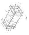
Figure 1 shows a perspective view, with some parts removed for clarity, of a first preferred embodiment of the shelter of the present invention; -
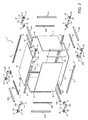
Figure 2 is an exploded view of the shelter inFigure 1 ; -
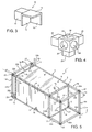
Figures 3 and 4 show, on an enlarged scale, respective details ofFigure 2 ; -
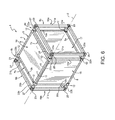
Figures 5 ,6 ,7 and8 show respective variants of the shelter inFigure 1 ; -
Figure 9 shows perspective views of a series of fitted-out panels suitable for being mounted on a shelter made according to the present invention; -
Figure 10 shows a perspective view of an example of the fitting out and installation of two shelters fromFigure 1 ; -
Figure 11 show a side elevation of the shelters inFigure 10 ; and -
Figure 12 show a side elevation of a variant of one of the shelters inFigure 11 . - In
Figure 1 , reference numeral 1 indicates, as a whole, a shelter, which is defined by a parallelepiped-shaped body having a substantially horizontallongitudinal axis 2. - Schematically, the shelter 1 is divisible into three main parts, integral with each other and aligned along axis 2:
- a central parallelepiped-
shaped box 3, preferable destined for use as a living and/or operations area, and - due
end portions box 3 and are preferable destined for being used as utility compartments, for example, for housing electrical and/or power systems and work equipment. - According to that shown in
Figures 1 and2 , the shelter 1 has a reticular load-bearing structure composed of three frameworks, rigidly connected to each other and comprising a framework 5 for thebox 3 and twoframeworks end portions - Framework 5 comprises two right-parallelogram-
shaped frames axis 2 and are connected to each other, at the respective vertices, by fourlongitudinal bars 8 parallel to each other and toaxis 2. -
Frames frame 7b in the case in point. -
Frame 7a (7b) lies on a plane perpendicular toaxis 2 and is formed by a pair oftransversal bars 9a (9b) parallel to each other and transversal toaxis 2 and by a pair ofvertical bars 10a (10b) perpendicular to thetransversal bars 9a (9b). - The
longitudinal bars 8,transversal bars 9a (9b) andvertical bars 10a (10b) are all of the same type and are obtained from metal section, in aluminium for example, with an L-shaped section comprising twoflat flanges 11 of substantially the same width, defining between them a right dihedral facingaxis 2 and possibly stiffened in the inner joint area. - Each
longitudinal bar 8 is rigidly connected at each of its free axial ends to a respective pair ofbars 9a (9b) and 10a (10b) of therespective frame 7a (7b) by arespective corner joint 12, which defines, together with theother corner joints 12, the eight vertices of thebox 3. - According to that shown in
Figures 1 and3 , eachcorner joint 12 is defined by three, substantially square,flat plates 13, each of which is integral with and perpendicular to the other two and is rigidly connected to theflanges 11 of two of the threebars corner joint 12 by means of screws or rivets or other similar connection elements. - Each
corner joint 12 further comprises a respective parallelepipedaltubular appendage 14, which projects from theplate 13 that is coplanar with theframe 7a (7b), is arranged with its two edges substantially coincident with two top edges of therespective corner joint 12 and, as shall be clarified further on, has the function of forming a plug-and-socket coupling between therespective corner joint 12 and a respective longitudinal element offramework - The
box 3 is externally delimited by a plurality of lateral panels comprising afloor 15, aceiling 16, twotransversal walls 17closing frames longitudinal walls 18, each one extending between a pair oflongitudinal bars 8 and twovertical bars lateral panels - As shall be seen in greater detail further on, the side panels, and in particular the
transversal walls 17 andlongitudinal walls 18, can be fitted out differently and include, for example, doors, windows, various types of openings and a multitude of accessories depending on the final usage of the shelter 1. - According to that shown in
Figures 1 and2 ,frameworks respective end portion axis 2. For this reason, and for motives of simplicity, explicit reference will only be made to one of theframeworks framework 6b in the case in point. -
Framework 6a (6b) is arranged facingframe 7a (7b) and comprises, in turn, aframe 19a (19b) that is substantially identical in shape and size toframe 7a (7b), lies on a plane perpendicular toaxis 2 and is formed by a pair oftransversal tubes 20a (20b), each of which is parallel to and facing a correspondingtransversal bar 9a (9b) offrame 7a, and by a pair ofvertical tubes 21a (21b), each of which is parallel to and facing a correspondingvertical bar 10a (10b) offrame 7a. -
Framework 6a (6b) further comprises fourlongitudinal tubes 22a (22b), each of which extends from a respective corner offrame 19a (19b) to a corresponding corner offrame 7a (7b) and is axially aligned with a respectivelongitudinal bar 8 of framework 5. - The
longitudinal tubes 22a (22b), thetransversal tubes 20a (20b) and thevertical tubes 21a (21b) are all of the same type and are obtained from a hollow metal section with a square cross-section. - Framework 6a (6b) and framework 5 are rigidly connected to each other by plug-and-socket couplings, each of which is made by the insertion of a
tubular appendage 14 inside an axial end of thelongitudinal tube 22a (22b) aligned with it. To ensure stability of the connection, the end of eachlongitudinal tube 22a (22b) is fastened to the respectivetubular appendage 14 by means of screws or rivets or other similar connection elements. - At the opposite axial end, each
longitudinal tube 22a (22b) is connected toframe 19a (19b) by acorner block 23, which defines, together with theother corner blocks 23, the vertices of the shelter 1. - In particular, according to that shown in
Figures 1 and4 , eachcorner block 23 connects alongitudinal tube 22a (22b), atransversal tube 20a (20b) and avertical tube 21a (21b) together and comprises a parallelepiped-shaped block 24 with square faces and threetubular appendages 25, which are identical totubular appendages 14 and are arranged on three respective faces of theblock 24, two-by-two contiguously. - In particular, each
tubular appendage 25 of eachcorner block 23 projects from the centre of the respective face of therespective block 24 and is firmly planted inside one of the ends of the three longitudinal 22a (22b), transversal 20a (20b) and vertical 21a (21b) tubes that converge to thecorner block 23. To ensure stability of the connection, each tube is fastened to the relatedtubular appendage 25 by means of screws or rivets or other similar connection elements. - Lastly, each
corner block 23 has ahole 26 on each of its two faces opposite to thetubular appendages 25 connected to thetransversal tube 20a (20b) and thelongitudinal tube 22a (22b), and a substantiallyelliptical slot 27, arranged with its larger axis parallel toaxis 2, on its face opposite to thetubular appendage 25 connected to thevertical tube 21a (21b). - Preferably, the size and shape of the
corner blocks 23, theholes 26 and theslots 27 are made in compliance with the ISO 1161 standards for containers in order to allow the shelter 1 to be lifted and secured on any means of transport equipped with standard coupling systems. - For the same reason, although they can be of any size, the longitudinal, transversal and vertical dimensions of the shelter 1 are preferably set in compliance with the ISO 668 standard for containers to allow, together with the ISO 1161 corner blocks, the transportability of the shelter 1 on any trailer equipped with the mentioned standard coupling systems. In particular, according to the mentioned ISO 668 standard, the standard transversal width is 8 feet, the standard height is 8 feet 6 inches, and the standard longitudinal lengths are 10, 20, 30 and 40 feet.
- From the foregoing description, it can be deduced that, unlike known shelters, which have a monolithic structure, this shelter 1 has a module-based structure (3, 4a, 4b), hereinafter indicated by the term "modular structure", which enables:
- moving the
corner blocks 23 on theend portions corner joints 12; - varying, within relatively broad limits and according to needs, the position of
box 3 along the shelter 1 by simply varying the length of thelongitudinal tubes -
pre-assembling frames transversal tubes vertical tubes - considerably reducing installation times and costs with respect to traditional shelters and, at the same time, offering an extremely flexible solution adaptable to all application requirements; and
- satisfying market demands with a minimum number of
boxes 3 being proposed, with a consequent reduction in the associated side panels (15-18) "in the catalogue". -
Figures 1 ,6 and7 show three shelters 1 having the same transversal width, the same height and different overall longitudinal lengths, in the cases in point, of 20, 10 and 30 feet. - In the shelter 1 shown in the attached figures, the overall longitudinal length is equal to the sum of the longitudinal length of the
box 3, namely the length of thelongitudinal bars 8, the length ofend portion 4a and the length of theend portion 4b, namely the lengths of thelongitudinal tubes - It follows that, once the overall length L that the shelter 1 must have is decided, the length of the
box 3 and the lengths of theend portions longitudinal bars 8 and of thelongitudinal tubes - In other words, by simply varying the length of the longitudinal components and adapting the size of the panels, the "modular structure" of the shelter 1 enables an overall size to be reached in compliance with the ISO 668 standard or, in any case, any overall size between the minimum and maximum limits set by standard rules, with evident advantages in terms of simplification and standardization of the structure's design.
- In this regard, the modularity of the shelter 1 renders the design of the shelter's mechanical structure advantageously practicable with the aid of software tools able to propose a list of components in conformity with the technical specifications and to check the dimensional and/or functional compatibility of the selected components.
- Another advantage consists in that, unlike traditional shelters, the assembly of the shelter 1 does not envisage welding operations on the components. In particular, the
longitudinal bars 8,transversal bars vertical bars - In each of the shelter 1 shown in
Figures 1 ,6 and7 , theend portions box 3. -
Figure 5 shows a shelter 1, in which the overall length and the length of thebox 3 are the same as those of the shelter inFigure 1 , except that unlike the latter, theend portions Figure 1 . - The above-stated considerations also hold for the shelter 1 in
Figure 8 compared to the shelter inFigure 7 . - Four types of fitted-out panels are show in
Figure 9 by way of example. In particular, the following are shown: - a
longitudinal wall 18 having an opening surrounded by a tubular accordion-like element 28, which is extended, in use, between the above-mentioned opening and an opening on the other shelter so as to define a passageway tunnel between the two shelters; - a
longitudinal wall 18 fitted with adoor 29 andlighting appliances 30; - a
longitudinal wall 18 fitted with amultifunction connector 31; and - a
longitudinal wall 18 fitted with openings closed by horizontally pivoted hatches 32. - A solution for the fitting out and installation of two shelters 1 is shown in
Figures 10 and11 , these being arranged with the respectivelongitudinal walls 18 side by side and provided with respective openings connected to each other by a tubular accordion-like element 28. One of the two shelters 1 (shown in the foreground ofFigure 10 ) is also provided with adoor 29, located on thelongitudinal wall 18 opposite to the one facing the other shelter 1, and is equipped withsolar panels 33 mounted on top of theceiling 16. - The
end portions side panels 34, each of which extends betweenframe 19a (or 19b) andframe 7a (or, respectively, 7b) parallel to a respectivelongitudinal wall 18 and carries a support and levelling device 35 (of known type) for the respective shelter 1. Theside panels 34 and thetransversal walls 17 are preferably provided with standard holes and coupling points able to facilitate the housing and fastening of any type of equipment and fittings inside theend portions - In the example shown, one
end portion 4a is dedicated to housing thecable storage reels 36, while theother end portion 4a is closed by a closing panel of the associatedframe 19a and houses a fire-fightingsystem 37. - The shelter in
Figure 12 is a variant of the shelter 1 shown in the foreground ofFigure 10 and differs from the latter in that, for the same overall length of the shelter 1, the ratio between the lengths of theend portions box 3 changes, and in that thedoor 29 is placed in the middle and not to one side of the respectivelongitudinal wall 18.
Claims (13)
- A shelter having a predetermined standard length and a longitudinal axis (2), and comprising a parallelepiped-shaped central element or module (3) and two parallelepiped-shaped end elements or modules (4a, 4b), which are aligned with the central module (3) along the longitudinal axis (2) and are rigidly connected to the central module (3) at respective opposite axial ends of the central module (3); the shelter (1) being characterized in that the central module (3) has a first length shorter than said standard length; and the end modules (4a, 4b) have respective second and third lengths, which are equal or different, but are complementary lengths so that their sum is equal to the difference between the standard length and the first length; the shelter (1) comprising a plurality of ISO-standard corner blocks (23) defining respective external vertices of the shelter (1).
- A shelter as claimed in Claim 1, wherein the central module (3) comprises a first framework (5) comprising a plurality of bars (8, 9a, 9b, 10a, 10b) and is closed by panels (15, 16, 17, 18) carried by the first framework (5), and each end module (4a; 4b) comprises a respective second framework (6a; 6b), structurally independent from the first framework (5) and comprising a plurality of tubes (20a, 20b, 21a, 21b, 22a, 22b) connected to one another by means of said ISO-standard corner blocks (23).
- A shelter as claimed in Claim 2, wherein the panels (15, 16, 17, 18) are arranged simply in contact with the framework (5) from the inside and are fixed in a removable manner, by means of screws, rivets or the like, to the respective bars (8, 9a, 9b, 10a, 10b) of the framework (5).
- A shelter as claimed in Claim 2 or 3, wherein the first framework (5) comprises two first frames (7a, 7b), which are identical, are right-parallelogram-shaped, are aligned to and spaced apart from one another along said longitudinal axis (2) and lie on respective planes perpendicular to the longitudinal axis (2), each first frame (7a, 7b) comprising a pair of transversal bars (9a, 9b) and a pair of vertical bars (10a, 10b) arranged at right angles to the transversal bars (9a, 9b), and wherein the first framework (5) further comprises four longitudinal bars (8), each of which is parallel to said longitudinal axis (2) and extends from an edge of a first frame (7a; 7b) to a corresponding edge of the other first frame (7b; 7a).
- A shelter as claimed in Claim 4, wherein, at each axial end, each longitudinal bar (8) is rigidly connected to an end of a respective transversal bar (9a; 9b) and to an end of a respective vertical bar (10a; 10b) by means of a corner joint (12), which defines, with the other corner joints (12), the eight vertices of the central module (3).
- A shelter as claimed in Claim 5, wherein each of said bars (8, 9a, 9b, 10a, 10b) is a metal L-shaped bar comprising two flat flanges (11) having substantially the same width and defining therebetween a right dihedral facing the longitudinal axis (2).
- A shelter as claimed in Claim 6, wherein each corner joint (12) is defined by three flat plates (13), each of which is integral with and perpendicular to the other two plates (13) and is rigidly connected, by means of screws, rivets or other analogous fastening means, to the flanges (11) of two of the three bars (8, 9a, 9b, 10a, 10b) that converge to the corner joint (12) itself.
- A shelter as claimed in one of Claims 4 to 7, wherein the form, the number and the arrangement of the respective components of said second frameworks (6a; 6b) are the same and can only differ with regard to their longitudinal dimension, i.e. the length, measured parallel to said longitudinal axis (2), of the respective end module (4a, 4b).
- A shelter as claimed in Claim 8, wherein each second framework (6a; 6b) comprises a second frame (19a; 19b), which faces a respective first frame (7a; 7b), has a form and dimensions identical to those of the first frames (7a, 7b), lies on a plane perpendicular to the longitudinal axis (2) and comprises a pair of transversal tubes (20a, 20b) and a pair of vertical tubes (21a, 21b) which are arranged at right angles to the transversal tubes (20a, 20b); each second framework (6a; 6b) further comprises four longitudinal tubes (22a, 22b), each of which is parallel to the longitudinal axis (2), extends from an edge of a second frame (19a; 19b) to an edge of a facing first frame (7a; 7b), and is aligned to a corresponding longitudinal bar (8).
- A shelter as claimed in Claim 9, wherein said transversal tubes (20a, 20b), vertical tubes (21a, 21b) and longitudinal tubes (22a, 22b) are hollow metal sections with a square cross section, each longitudinal tube (22a; 22b) being connected, at one axial end, to an end of a transversal tube (20a; 20b) and an end of a vertical tube (21a; 21b) by means of a said ISO-standard corner block (23).
- A shelter as claimed in Claim 10 when appended to Claim 7, wherein, at its axial end facing the first frame (7a; 7b), each longitudinal tube (22a; 22b) is rigidly connected to a respective said corner joint (12) by means of a plug-and-socket coupling.
- A shelter as claimed in Claim 11, wherein each corner joint (12) has a projecting element (14), which projects from the respective first frame (7a; 7b) toward the second frame (19a; 19b) facing the first frame (7a; 7b) and is fitted inside an axial end of a respective said longitudinal tube (22a; 22b) to define the respective said plug-and-socket coupling.
- A shelter as claimed in one of Claims 4 to 12, wherein said panels (15, 16, 17, 18) are releasably mounted on the first framework (5), are, at least in part, fitted-out panels, and comprise a floor (15), a ceiling (16), two transversal walls (17) each closing a respective first frame (7a; 7b) and two longitudinal walls (18), each of which extends between a respective pair of longitudinal bars (8) and two respective vertical bars (10a, 10b).
Priority Applications (1)
| Application Number | Priority Date | Filing Date | Title |
|---|---|---|---|
| PL12172302T PL2535471T3 (en) | 2011-06-15 | 2012-06-15 | Shelter |
Applications Claiming Priority (1)
| Application Number | Priority Date | Filing Date | Title |
|---|---|---|---|
| ITTO20110529 | 2011-06-15 |
Publications (2)
| Publication Number | Publication Date |
|---|---|
| EP2535471A1 true EP2535471A1 (en) | 2012-12-19 |
| EP2535471B1 EP2535471B1 (en) | 2017-02-01 |
Family
ID=44555158
Family Applications (1)
| Application Number | Title | Priority Date | Filing Date |
|---|---|---|---|
| EP12172302.7A Active EP2535471B1 (en) | 2011-06-15 | 2012-06-15 | Shelter |
Country Status (4)
| Country | Link |
|---|---|
| US (1) | US20130036702A1 (en) |
| EP (1) | EP2535471B1 (en) |
| IT (1) | ITTO20120520A1 (en) |
| PL (1) | PL2535471T3 (en) |
Cited By (6)
| Publication number | Priority date | Publication date | Assignee | Title |
|---|---|---|---|---|
| WO2014173405A3 (en) * | 2013-04-24 | 2015-06-25 | Harald Martin | Room system |
| DE102016215254A1 (en) * | 2016-08-16 | 2018-02-22 | Fraunhofer-Gesellschaft zur Förderung der angewandten Forschung e.V. | Apparatus and method for protecting externally exposed objects |
| IT202000011119A1 (en) * | 2020-05-14 | 2021-11-14 | Novadria Srl | MODULAR SECTIONAL UNIT FOR THE RAPID CONSTRUCTION OF EMERGENCY HEALTHCARE STRUCTURES. |
| EP3951119A4 (en) * | 2019-04-05 | 2022-12-28 | NTN Corporation | PORTABLE FACILITY EQUIPPED WITH A NATURAL ENERGY GENERATION UNIT |
| DE102024205270A1 (en) * | 2024-06-07 | 2025-12-11 | HT Group GmbH | Technical building as well as prefabricated room modules and technical modules for such a technical building |
| US12595651B2 (en) | 2020-03-16 | 2026-04-07 | Cubit Building Company Ehf | System for architectural modular building construction |
Families Citing this family (44)
| Publication number | Priority date | Publication date | Assignee | Title |
|---|---|---|---|---|
| US9121168B2 (en) * | 2010-01-06 | 2015-09-01 | Home Ec. | Modular housing |
| US8800215B2 (en) * | 2011-08-22 | 2014-08-12 | Performance Contracting, Inc. | Self-contained portable container habitat for use in radiological environments |
| WO2013074894A1 (en) * | 2011-11-17 | 2013-05-23 | The Board Of Trustees Of The Leland Stanford Junior University | Dedicated cardiac pet |
| CA2862083C (en) | 2012-01-23 | 2018-07-17 | Inter Hospitality Holding B.V. | Prefabricated module for a building |
| PL2617911T3 (en) * | 2012-01-23 | 2016-11-30 | Method and system for construction of a building | |
| WO2013110618A1 (en) | 2012-01-23 | 2013-08-01 | Inter Hospitality Holding B.V. | Prefabricated panel for a building |
| AU2013100359B4 (en) * | 2012-07-11 | 2013-11-28 | 1Space Pty Ltd | Modular Building |
| CA162506S (en) | 2013-07-22 | 2015-06-25 | Vastint Hospitality B V | Prefabricated living unit |
| US9441359B1 (en) * | 2015-01-13 | 2016-09-13 | Tommy Hsieh | Structurally independent frame for component based multi-unit buildings |
| USD761548S1 (en) * | 2015-02-22 | 2016-07-19 | Rand Elliott | Tubing walker |
| US10260227B2 (en) * | 2015-06-09 | 2019-04-16 | Rock West Composites, Inc. | Tubular framing system and method |
| NL2015625B1 (en) * | 2015-10-15 | 2017-01-24 | J A S F Beheer B V | Building space divider system |
| ITUB20169963A1 (en) * | 2016-01-13 | 2017-07-13 | Federico Lestini | Modular building structure with integrated systems |
| US20200032504A1 (en) * | 2016-11-10 | 2020-01-30 | Jong Woon Song | Movable house |
| US20180238041A1 (en) | 2017-02-21 | 2018-08-23 | Styrc Jacek | Modular furniture system |
| CN106915388B (en) * | 2017-02-27 | 2023-01-10 | 江苏捷诚车载电子信息工程有限公司 | Carbon Fiber Rectangular Tube Connection Device for Lightweight Shelter Frame Structure |
| US10415263B2 (en) * | 2017-04-26 | 2019-09-17 | New House International Corp | Packaged container housing structure and construction method |
| US10648169B2 (en) | 2017-04-26 | 2020-05-12 | New House International Corp. | Packaged container housing structure and construction method |
| USD887025S1 (en) | 2017-11-17 | 2020-06-09 | 2724889 Ontario Inc. | Connector for a modular structure |
| DE102018127871B4 (en) * | 2018-11-08 | 2020-07-16 | Ernst-Peter Amat Kreft | Assembly kit and method for positive and / or non-positive pre-assembly for a frame construction and use |
| CN111321812B (en) * | 2018-12-14 | 2021-10-29 | 宋钟沄 | Assembled panel structure |
| US11118798B2 (en) * | 2019-03-08 | 2021-09-14 | Johnson Controls Technology Company | Composite roof structure for air handling units |
| US11236505B2 (en) * | 2019-05-15 | 2022-02-01 | Cover Technologies, Inc. | Panelized structural building system |
| USD938772S1 (en) | 2020-02-04 | 2021-12-21 | 2724889 Ontario Inc. | Connector |
| USD952382S1 (en) | 2020-02-04 | 2022-05-24 | 2724889 Ontario Inc. | Table |
| USD938770S1 (en) | 2020-02-04 | 2021-12-21 | 2724889 Ontario Inc. | Connector |
| USD938771S1 (en) | 2020-02-04 | 2021-12-21 | 2724889 Ontario Inc. | Connector |
| USD952384S1 (en) | 2020-02-04 | 2022-05-24 | 2724889 Ontario Inc. | Leg |
| USD936859S1 (en) | 2020-02-04 | 2021-11-23 | 2724889 Ontario Inc. | Connector |
| CN111734173A (en) * | 2020-07-01 | 2020-10-02 | 广州番禺职业技术学院 | A recyclable self-build exhibition hall |
| USD936861S1 (en) | 2020-08-12 | 2021-11-23 | 2724889 Ontario Inc. | Connector for a modular structure |
| USD936247S1 (en) | 2020-08-12 | 2021-11-16 | 2724889 Ontario Inc. | Connector for a modular structure |
| USD938068S1 (en) | 2020-08-12 | 2021-12-07 | 2724889 Ontario Inc. | Connector for a modular structure |
| USD939731S1 (en) | 2020-08-12 | 2021-12-28 | 2724889 Ontario Inc. | Connector for a modular structure |
| USD938619S1 (en) | 2020-08-12 | 2021-12-14 | 2724889 Ontario Inc. | Connector for a modular structure |
| USD939106S1 (en) | 2020-08-12 | 2021-12-21 | 2724889 Ontario Inc. | Connector for a modular structure |
| USD936246S1 (en) | 2020-08-12 | 2021-11-16 | 2724889 Ontario Inc. | Connector for a modular structure |
| CN112124627A (en) * | 2020-09-28 | 2020-12-25 | 中国科学院微小卫星创新研究院 | A flexible satellite platform structure |
| DE102020132499A1 (en) | 2020-12-07 | 2022-06-09 | Scharenberg Industrieanlagen GmbH | Soundproof cabin and cabin module |
| US11879257B2 (en) * | 2020-12-26 | 2024-01-23 | Steve T. Everett | Shipping container based portable temporary/relief housing unit |
| US20220203157A1 (en) * | 2020-12-30 | 2022-06-30 | RPM Fitness, Inc. | Exercise box |
| WO2023276821A1 (en) * | 2021-06-29 | 2023-01-05 | Ntn株式会社 | Mobile structure, and structural unit |
| US20230160196A1 (en) * | 2021-11-23 | 2023-05-25 | Optima, Inc. | Modular habitable structures, and associated systems and methods |
| US11773612B1 (en) * | 2022-05-31 | 2023-10-03 | Shawn McNeilly | Temporary homeless shelter |
Citations (1)
| Publication number | Priority date | Publication date | Assignee | Title |
|---|---|---|---|---|
| DE202008005946U1 (en) * | 2008-04-30 | 2008-07-31 | Macrander Gmbh | Cost-effective environmentally friendly large container for the transport of different goods with reduced transport costs and low environmental impact |
Family Cites Families (16)
| Publication number | Priority date | Publication date | Assignee | Title |
|---|---|---|---|---|
| US3459326A (en) * | 1968-05-31 | 1969-08-05 | Christopher H Betjemann | Shipping gondola with removable side rails |
| US4325488A (en) * | 1979-08-23 | 1982-04-20 | The Boeing Company | Lightweight cargo container and fittings |
| US4545169A (en) * | 1983-06-14 | 1985-10-08 | Polyfab S.A.R.L. | Prefabricated transportable concrete floor system and method for producing same |
| US4599829A (en) * | 1983-08-25 | 1986-07-15 | Tandemloc, Inc. | Modular container building system |
| SE448399B (en) * | 1986-04-07 | 1987-02-16 | Bahco Ventilation Ab | FRAMEWORK FOR THE BUILDING OF CHARACTERISTIC WRAPS |
| US4854094A (en) * | 1987-11-23 | 1989-08-08 | Clark Phillip C | Method for converting one or more steel shipping containers into a habitable building at a building site and the product thereof |
| US5403063A (en) * | 1993-05-21 | 1995-04-04 | Sjostedt; Robbie J. | Modular integral floor construction for vehicle body |
| US5449081A (en) * | 1993-05-21 | 1995-09-12 | Stoughton Composites, Inc. | Modular insulated intermodal container construction |
| US5403062A (en) * | 1993-05-21 | 1995-04-04 | Stoughton Composites, Inc. | Panel joint for adhesively bonded wall panels |
| US5741042A (en) * | 1995-03-23 | 1998-04-21 | Stoughton Composites, Inc. | Intermodal container including double lap shear joints |
| US5713651A (en) * | 1996-02-27 | 1998-02-03 | Mcquay International | Modular frame assembly for an equipment cabinet |
| NL1006974C2 (en) * | 1997-09-08 | 1999-03-09 | Holland Heating Bv | Air handling unit assembly and air treatment unit comprising this assembly. |
| US6826879B1 (en) * | 1999-02-19 | 2004-12-07 | Cathartes Investment | Modular building construction |
| US6688712B2 (en) * | 2001-07-13 | 2004-02-10 | Carrier Corporation | Detachable frame for coil removal |
| US7418802B2 (en) * | 2005-09-09 | 2008-09-02 | Gichner Systems Group, Inc. | Expandable shelter system |
| GB2476102A (en) * | 2009-12-14 | 2011-06-15 | Key Housing Ltd | Transportable modular building construction system |
-
2012
- 2012-06-14 IT IT000520A patent/ITTO20120520A1/en unknown
- 2012-06-15 PL PL12172302T patent/PL2535471T3/en unknown
- 2012-06-15 US US13/524,109 patent/US20130036702A1/en not_active Abandoned
- 2012-06-15 EP EP12172302.7A patent/EP2535471B1/en active Active
Patent Citations (1)
| Publication number | Priority date | Publication date | Assignee | Title |
|---|---|---|---|---|
| DE202008005946U1 (en) * | 2008-04-30 | 2008-07-31 | Macrander Gmbh | Cost-effective environmentally friendly large container for the transport of different goods with reduced transport costs and low environmental impact |
Cited By (8)
| Publication number | Priority date | Publication date | Assignee | Title |
|---|---|---|---|---|
| WO2014173405A3 (en) * | 2013-04-24 | 2015-06-25 | Harald Martin | Room system |
| CN105358779A (en) * | 2013-04-24 | 2016-02-24 | 哈莱尔德·马丁 | Room system |
| DE102016215254A1 (en) * | 2016-08-16 | 2018-02-22 | Fraunhofer-Gesellschaft zur Förderung der angewandten Forschung e.V. | Apparatus and method for protecting externally exposed objects |
| EP3951119A4 (en) * | 2019-04-05 | 2022-12-28 | NTN Corporation | PORTABLE FACILITY EQUIPPED WITH A NATURAL ENERGY GENERATION UNIT |
| US12234634B2 (en) | 2019-04-05 | 2025-02-25 | Ntn Corporation | Portable facility provided with natural energy power generation unit |
| US12595651B2 (en) | 2020-03-16 | 2026-04-07 | Cubit Building Company Ehf | System for architectural modular building construction |
| IT202000011119A1 (en) * | 2020-05-14 | 2021-11-14 | Novadria Srl | MODULAR SECTIONAL UNIT FOR THE RAPID CONSTRUCTION OF EMERGENCY HEALTHCARE STRUCTURES. |
| DE102024205270A1 (en) * | 2024-06-07 | 2025-12-11 | HT Group GmbH | Technical building as well as prefabricated room modules and technical modules for such a technical building |
Also Published As
| Publication number | Publication date |
|---|---|
| US20130036702A1 (en) | 2013-02-14 |
| ITTO20120520A1 (en) | 2012-12-16 |
| EP2535471B1 (en) | 2017-02-01 |
| PL2535471T3 (en) | 2017-07-31 |
Similar Documents
| Publication | Publication Date | Title |
|---|---|---|
| US20130036702A1 (en) | Shelter | |
| CN107816613B (en) | Assembling support for installing communication equipment and combined structure of assembling support and communication equipment | |
| ES2578785T3 (en) | Procedure and system for the construction of a building | |
| KR101625847B1 (en) | Assembly structure of residential container | |
| EP2780515B1 (en) | Mobile sanitary unit for accommodating at least three sanitary facilities | |
| US10501928B2 (en) | Split connector and modular frame comprising such a split connector | |
| CN110528917B (en) | Octagonal modular assembly type structure of operating room | |
| US20110214362A1 (en) | Modular Architecture | |
| US9209433B2 (en) | Riveted module | |
| WO2012099531A1 (en) | Multi-purpose mobile modular structure | |
| WO2017025847A1 (en) | Convertible shipping container and building fixture apparatus | |
| WO2001001533A1 (en) | Frame structure for an enclosure for electrical equipment | |
| WO2020091721A1 (en) | Energy storage array including transportable storage container having connector channel | |
| KR101310641B1 (en) | foldable wall | |
| CN110528918B (en) | Arc modularized assembly structure of operating room | |
| US20140259981A1 (en) | Storage building and a roof panel system for use with storage buildings | |
| KR20190034988A (en) | Module assembly type prefabricated house | |
| JP2012166842A (en) | Raisable container | |
| US20140352247A1 (en) | Framework serving as structural support and utility space | |
| GB2510532A (en) | Supporting device for a furniture device, in particular for a partition | |
| CN201752064U (en) | Modular frame device | |
| CN213838022U (en) | Novel protection is used in construction device | |
| CN211499348U (en) | Bear formula building curtain and decorate component and building curtain | |
| EP2357291A1 (en) | Modular architecture | |
| US20130153337A1 (en) | Scaffold module |
Legal Events
| Date | Code | Title | Description |
|---|---|---|---|
| PUAI | Public reference made under article 153(3) epc to a published international application that has entered the european phase |
Free format text: ORIGINAL CODE: 0009012 |
|
| AK | Designated contracting states |
Kind code of ref document: A1 Designated state(s): AL AT BE BG CH CY CZ DE DK EE ES FI FR GB GR HR HU IE IS IT LI LT LU LV MC MK MT NL NO PL PT RO RS SE SI SK SM TR |
|
| AX | Request for extension of the european patent |
Extension state: BA ME |
|
| 17P | Request for examination filed |
Effective date: 20130619 |
|
| RBV | Designated contracting states (corrected) |
Designated state(s): AL AT BE BG CH CY CZ DE DK EE ES FI FR GB GR HR HU IE IS IT LI LT LU LV MC MK MT NL NO PL PT RO RS SE SI SK SM TR |
|
| 17Q | First examination report despatched |
Effective date: 20160624 |
|
| GRAP | Despatch of communication of intention to grant a patent |
Free format text: ORIGINAL CODE: EPIDOSNIGR1 |
|
| INTG | Intention to grant announced |
Effective date: 20160831 |
|
| RAP1 | Party data changed (applicant data changed or rights of an application transferred) |
Owner name: LEONARDO S.P.A. |
|
| GRAS | Grant fee paid |
Free format text: ORIGINAL CODE: EPIDOSNIGR3 |
|
| GRAA | (expected) grant |
Free format text: ORIGINAL CODE: 0009210 |
|
| RIN1 | Information on inventor provided before grant (corrected) |
Inventor name: D'HARMANT, CARLO Inventor name: BAGLIONI, STEFANO Inventor name: PACETTI, STEFANO Inventor name: DE FAZIO, MARCO Inventor name: VITUCCI, MARCO Inventor name: TEGLIA, MARIO |
|
| AK | Designated contracting states |
Kind code of ref document: B1 Designated state(s): AL AT BE BG CH CY CZ DE DK EE ES FI FR GB GR HR HU IE IS IT LI LT LU LV MC MK MT NL NO PL PT RO RS SE SI SK SM TR |
|
| REG | Reference to a national code |
Ref country code: GB Ref legal event code: FG4D |
|
| REG | Reference to a national code |
Ref country code: CH Ref legal event code: EP Ref country code: AT Ref legal event code: REF Ref document number: 865732 Country of ref document: AT Kind code of ref document: T Effective date: 20170215 |
|
| REG | Reference to a national code |
Ref country code: IE Ref legal event code: FG4D |
|
| REG | Reference to a national code |
Ref country code: DE Ref legal event code: R096 Ref document number: 602012028171 Country of ref document: DE |
|
| REG | Reference to a national code |
Ref country code: NL Ref legal event code: MP Effective date: 20170201 |
|
| REG | Reference to a national code |
Ref country code: LT Ref legal event code: MG4D |
|
| REG | Reference to a national code |
Ref country code: AT Ref legal event code: MK05 Ref document number: 865732 Country of ref document: AT Kind code of ref document: T Effective date: 20170201 |
|
| REG | Reference to a national code |
Ref country code: FR Ref legal event code: PLFP Year of fee payment: 6 |
|
| PG25 | Lapsed in a contracting state [announced via postgrant information from national office to epo] |
Ref country code: LT Free format text: LAPSE BECAUSE OF FAILURE TO SUBMIT A TRANSLATION OF THE DESCRIPTION OR TO PAY THE FEE WITHIN THE PRESCRIBED TIME-LIMIT Effective date: 20170201 Ref country code: NO Free format text: LAPSE BECAUSE OF FAILURE TO SUBMIT A TRANSLATION OF THE DESCRIPTION OR TO PAY THE FEE WITHIN THE PRESCRIBED TIME-LIMIT Effective date: 20170501 Ref country code: GR Free format text: LAPSE BECAUSE OF FAILURE TO SUBMIT A TRANSLATION OF THE DESCRIPTION OR TO PAY THE FEE WITHIN THE PRESCRIBED TIME-LIMIT Effective date: 20170502 Ref country code: HR Free format text: LAPSE BECAUSE OF FAILURE TO SUBMIT A TRANSLATION OF THE DESCRIPTION OR TO PAY THE FEE WITHIN THE PRESCRIBED TIME-LIMIT Effective date: 20170201 Ref country code: FI Free format text: LAPSE BECAUSE OF FAILURE TO SUBMIT A TRANSLATION OF THE DESCRIPTION OR TO PAY THE FEE WITHIN THE PRESCRIBED TIME-LIMIT Effective date: 20170201 Ref country code: IS Free format text: LAPSE BECAUSE OF FAILURE TO SUBMIT A TRANSLATION OF THE DESCRIPTION OR TO PAY THE FEE WITHIN THE PRESCRIBED TIME-LIMIT Effective date: 20170601 |
|
| PG25 | Lapsed in a contracting state [announced via postgrant information from national office to epo] |
Ref country code: ES Free format text: LAPSE BECAUSE OF FAILURE TO SUBMIT A TRANSLATION OF THE DESCRIPTION OR TO PAY THE FEE WITHIN THE PRESCRIBED TIME-LIMIT Effective date: 20170201 Ref country code: PT Free format text: LAPSE BECAUSE OF FAILURE TO SUBMIT A TRANSLATION OF THE DESCRIPTION OR TO PAY THE FEE WITHIN THE PRESCRIBED TIME-LIMIT Effective date: 20170601 Ref country code: SE Free format text: LAPSE BECAUSE OF FAILURE TO SUBMIT A TRANSLATION OF THE DESCRIPTION OR TO PAY THE FEE WITHIN THE PRESCRIBED TIME-LIMIT Effective date: 20170201 Ref country code: RS Free format text: LAPSE BECAUSE OF FAILURE TO SUBMIT A TRANSLATION OF THE DESCRIPTION OR TO PAY THE FEE WITHIN THE PRESCRIBED TIME-LIMIT Effective date: 20170201 Ref country code: AT Free format text: LAPSE BECAUSE OF FAILURE TO SUBMIT A TRANSLATION OF THE DESCRIPTION OR TO PAY THE FEE WITHIN THE PRESCRIBED TIME-LIMIT Effective date: 20170201 Ref country code: LV Free format text: LAPSE BECAUSE OF FAILURE TO SUBMIT A TRANSLATION OF THE DESCRIPTION OR TO PAY THE FEE WITHIN THE PRESCRIBED TIME-LIMIT Effective date: 20170201 Ref country code: NL Free format text: LAPSE BECAUSE OF FAILURE TO SUBMIT A TRANSLATION OF THE DESCRIPTION OR TO PAY THE FEE WITHIN THE PRESCRIBED TIME-LIMIT Effective date: 20170201 Ref country code: BG Free format text: LAPSE BECAUSE OF FAILURE TO SUBMIT A TRANSLATION OF THE DESCRIPTION OR TO PAY THE FEE WITHIN THE PRESCRIBED TIME-LIMIT Effective date: 20170501 |
|
| PG25 | Lapsed in a contracting state [announced via postgrant information from national office to epo] |
Ref country code: CZ Free format text: LAPSE BECAUSE OF FAILURE TO SUBMIT A TRANSLATION OF THE DESCRIPTION OR TO PAY THE FEE WITHIN THE PRESCRIBED TIME-LIMIT Effective date: 20170201 Ref country code: RO Free format text: LAPSE BECAUSE OF FAILURE TO SUBMIT A TRANSLATION OF THE DESCRIPTION OR TO PAY THE FEE WITHIN THE PRESCRIBED TIME-LIMIT Effective date: 20170201 Ref country code: SK Free format text: LAPSE BECAUSE OF FAILURE TO SUBMIT A TRANSLATION OF THE DESCRIPTION OR TO PAY THE FEE WITHIN THE PRESCRIBED TIME-LIMIT Effective date: 20170201 Ref country code: EE Free format text: LAPSE BECAUSE OF FAILURE TO SUBMIT A TRANSLATION OF THE DESCRIPTION OR TO PAY THE FEE WITHIN THE PRESCRIBED TIME-LIMIT Effective date: 20170201 Ref country code: IT Free format text: LAPSE BECAUSE OF FAILURE TO SUBMIT A TRANSLATION OF THE DESCRIPTION OR TO PAY THE FEE WITHIN THE PRESCRIBED TIME-LIMIT Effective date: 20170201 |
|
| REG | Reference to a national code |
Ref country code: DE Ref legal event code: R097 Ref document number: 602012028171 Country of ref document: DE |
|
| PG25 | Lapsed in a contracting state [announced via postgrant information from national office to epo] |
Ref country code: SM Free format text: LAPSE BECAUSE OF FAILURE TO SUBMIT A TRANSLATION OF THE DESCRIPTION OR TO PAY THE FEE WITHIN THE PRESCRIBED TIME-LIMIT Effective date: 20170201 Ref country code: DK Free format text: LAPSE BECAUSE OF FAILURE TO SUBMIT A TRANSLATION OF THE DESCRIPTION OR TO PAY THE FEE WITHIN THE PRESCRIBED TIME-LIMIT Effective date: 20170201 |
|
| PLBE | No opposition filed within time limit |
Free format text: ORIGINAL CODE: 0009261 |
|
| STAA | Information on the status of an ep patent application or granted ep patent |
Free format text: STATUS: NO OPPOSITION FILED WITHIN TIME LIMIT |
|
| 26N | No opposition filed |
Effective date: 20171103 |
|
| PG25 | Lapsed in a contracting state [announced via postgrant information from national office to epo] |
Ref country code: MC Free format text: LAPSE BECAUSE OF FAILURE TO SUBMIT A TRANSLATION OF THE DESCRIPTION OR TO PAY THE FEE WITHIN THE PRESCRIBED TIME-LIMIT Effective date: 20170201 |
|
| REG | Reference to a national code |
Ref country code: CH Ref legal event code: PL |
|
| PG25 | Lapsed in a contracting state [announced via postgrant information from national office to epo] |
Ref country code: SI Free format text: LAPSE BECAUSE OF FAILURE TO SUBMIT A TRANSLATION OF THE DESCRIPTION OR TO PAY THE FEE WITHIN THE PRESCRIBED TIME-LIMIT Effective date: 20170201 |
|
| REG | Reference to a national code |
Ref country code: IE Ref legal event code: MM4A |
|
| PG25 | Lapsed in a contracting state [announced via postgrant information from national office to epo] |
Ref country code: LU Free format text: LAPSE BECAUSE OF NON-PAYMENT OF DUE FEES Effective date: 20170615 Ref country code: CH Free format text: LAPSE BECAUSE OF NON-PAYMENT OF DUE FEES Effective date: 20170630 Ref country code: IE Free format text: LAPSE BECAUSE OF NON-PAYMENT OF DUE FEES Effective date: 20170615 Ref country code: LI Free format text: LAPSE BECAUSE OF NON-PAYMENT OF DUE FEES Effective date: 20170630 |
|
| REG | Reference to a national code |
Ref country code: BE Ref legal event code: MM Effective date: 20170630 |
|
| REG | Reference to a national code |
Ref country code: FR Ref legal event code: PLFP Year of fee payment: 7 |
|
| PG25 | Lapsed in a contracting state [announced via postgrant information from national office to epo] |
Ref country code: BE Free format text: LAPSE BECAUSE OF NON-PAYMENT OF DUE FEES Effective date: 20170630 |
|
| PG25 | Lapsed in a contracting state [announced via postgrant information from national office to epo] |
Ref country code: MT Free format text: LAPSE BECAUSE OF NON-PAYMENT OF DUE FEES Effective date: 20170615 |
|
| PG25 | Lapsed in a contracting state [announced via postgrant information from national office to epo] |
Ref country code: HU Free format text: LAPSE BECAUSE OF FAILURE TO SUBMIT A TRANSLATION OF THE DESCRIPTION OR TO PAY THE FEE WITHIN THE PRESCRIBED TIME-LIMIT; INVALID AB INITIO Effective date: 20120615 |
|
| PG25 | Lapsed in a contracting state [announced via postgrant information from national office to epo] |
Ref country code: CY Free format text: LAPSE BECAUSE OF NON-PAYMENT OF DUE FEES Effective date: 20170201 |
|
| PG25 | Lapsed in a contracting state [announced via postgrant information from national office to epo] |
Ref country code: MK Free format text: LAPSE BECAUSE OF FAILURE TO SUBMIT A TRANSLATION OF THE DESCRIPTION OR TO PAY THE FEE WITHIN THE PRESCRIBED TIME-LIMIT Effective date: 20170201 |
|
| PG25 | Lapsed in a contracting state [announced via postgrant information from national office to epo] |
Ref country code: TR Free format text: LAPSE BECAUSE OF FAILURE TO SUBMIT A TRANSLATION OF THE DESCRIPTION OR TO PAY THE FEE WITHIN THE PRESCRIBED TIME-LIMIT Effective date: 20170201 |
|
| PG25 | Lapsed in a contracting state [announced via postgrant information from national office to epo] |
Ref country code: AL Free format text: LAPSE BECAUSE OF FAILURE TO SUBMIT A TRANSLATION OF THE DESCRIPTION OR TO PAY THE FEE WITHIN THE PRESCRIBED TIME-LIMIT Effective date: 20170201 |
|
| PGFP | Annual fee paid to national office [announced via postgrant information from national office to epo] |
Ref country code: PL Payment date: 20240522 Year of fee payment: 13 |
|
| PGFP | Annual fee paid to national office [announced via postgrant information from national office to epo] |
Ref country code: DE Payment date: 20250626 Year of fee payment: 14 |
|
| PGFP | Annual fee paid to national office [announced via postgrant information from national office to epo] |
Ref country code: GB Payment date: 20250617 Year of fee payment: 14 |
|
| PGFP | Annual fee paid to national office [announced via postgrant information from national office to epo] |
Ref country code: FR Payment date: 20250624 Year of fee payment: 14 |