EP2535105A1 - Systems and methods for scale-up of microreactors - Google Patents
Systems and methods for scale-up of microreactors Download PDFInfo
- Publication number
- EP2535105A1 EP2535105A1 EP11305743A EP11305743A EP2535105A1 EP 2535105 A1 EP2535105 A1 EP 2535105A1 EP 11305743 A EP11305743 A EP 11305743A EP 11305743 A EP11305743 A EP 11305743A EP 2535105 A1 EP2535105 A1 EP 2535105A1
- Authority
- EP
- European Patent Office
- Prior art keywords
- pilot
- production
- heat transfer
- channel
- lab
- Prior art date
- Legal status (The legal status is an assumption and is not a legal conclusion. Google has not performed a legal analysis and makes no representation as to the accuracy of the status listed.)
- Withdrawn
Links
- 238000000034 method Methods 0.000 title claims abstract description 67
- 238000013341 scale-up Methods 0.000 title claims abstract description 9
- 238000004519 manufacturing process Methods 0.000 claims abstract description 57
- 238000012546 transfer Methods 0.000 claims abstract description 52
- 230000008569 process Effects 0.000 claims abstract description 40
- 239000000463 material Substances 0.000 claims abstract description 33
- 238000009533 lab test Methods 0.000 claims abstract description 12
- 239000012530 fluid Substances 0.000 claims description 35
- 238000006243 chemical reaction Methods 0.000 claims description 13
- 239000011521 glass Substances 0.000 claims description 10
- HBMJWWWQQXIZIP-UHFFFAOYSA-N silicon carbide Chemical group [Si+]#[C-] HBMJWWWQQXIZIP-UHFFFAOYSA-N 0.000 claims description 4
- 229910010271 silicon carbide Inorganic materials 0.000 claims description 4
- 238000006276 transfer reaction Methods 0.000 claims description 4
- 239000000919 ceramic Substances 0.000 claims 1
- 230000008859 change Effects 0.000 description 7
- 238000011161 development Methods 0.000 description 5
- 230000000694 effects Effects 0.000 description 5
- 238000002156 mixing Methods 0.000 description 5
- XLYOFNOQVPJJNP-UHFFFAOYSA-N water Substances O XLYOFNOQVPJJNP-UHFFFAOYSA-N 0.000 description 5
- 230000015572 biosynthetic process Effects 0.000 description 4
- 238000013461 design Methods 0.000 description 4
- 238000009826 distribution Methods 0.000 description 4
- 239000000203 mixture Substances 0.000 description 4
- 238000012545 processing Methods 0.000 description 4
- 230000009467 reduction Effects 0.000 description 4
- 238000003786 synthesis reaction Methods 0.000 description 4
- 238000012360 testing method Methods 0.000 description 4
- 230000008901 benefit Effects 0.000 description 3
- 238000005516 engineering process Methods 0.000 description 3
- 230000000704 physical effect Effects 0.000 description 3
- 238000007796 conventional method Methods 0.000 description 2
- 238000005259 measurement Methods 0.000 description 2
- 238000005457 optimization Methods 0.000 description 2
- 230000002411 adverse Effects 0.000 description 1
- 238000006136 alcoholysis reaction Methods 0.000 description 1
- 238000005882 aldol condensation reaction Methods 0.000 description 1
- 230000029936 alkylation Effects 0.000 description 1
- 238000005804 alkylation reaction Methods 0.000 description 1
- PNEYBMLMFCGWSK-UHFFFAOYSA-N aluminium oxide Inorganic materials [O-2].[O-2].[O-2].[Al+3].[Al+3] PNEYBMLMFCGWSK-UHFFFAOYSA-N 0.000 description 1
- 230000009435 amidation Effects 0.000 description 1
- 238000007112 amidation reaction Methods 0.000 description 1
- 238000005576 amination reaction Methods 0.000 description 1
- 238000005915 ammonolysis reaction Methods 0.000 description 1
- 238000006254 arylation reaction Methods 0.000 description 1
- 150000001540 azides Chemical class 0.000 description 1
- 230000009286 beneficial effect Effects 0.000 description 1
- 230000003851 biochemical process Effects 0.000 description 1
- 238000004364 calculation method Methods 0.000 description 1
- 230000006315 carbonylation Effects 0.000 description 1
- 238000005810 carbonylation reaction Methods 0.000 description 1
- 230000021523 carboxylation Effects 0.000 description 1
- 238000006473 carboxylation reaction Methods 0.000 description 1
- 239000002131 composite material Substances 0.000 description 1
- 238000005859 coupling reaction Methods 0.000 description 1
- 238000002425 crystallisation Methods 0.000 description 1
- 230000008025 crystallization Effects 0.000 description 1
- 230000020335 dealkylation Effects 0.000 description 1
- 238000006900 dealkylation reaction Methods 0.000 description 1
- 238000006114 decarboxylation reaction Methods 0.000 description 1
- 238000005695 dehalogenation reaction Methods 0.000 description 1
- 230000018044 dehydration Effects 0.000 description 1
- 238000006297 dehydration reaction Methods 0.000 description 1
- 238000006356 dehydrogenation reaction Methods 0.000 description 1
- 238000006704 dehydrohalogenation reaction Methods 0.000 description 1
- 239000004205 dimethyl polysiloxane Substances 0.000 description 1
- 235000013870 dimethyl polysiloxane Nutrition 0.000 description 1
- 230000008030 elimination Effects 0.000 description 1
- 238000003379 elimination reaction Methods 0.000 description 1
- 238000005265 energy consumption Methods 0.000 description 1
- 230000007613 environmental effect Effects 0.000 description 1
- 230000002255 enzymatic effect Effects 0.000 description 1
- 238000006911 enzymatic reaction Methods 0.000 description 1
- 238000006735 epoxidation reaction Methods 0.000 description 1
- 230000032050 esterification Effects 0.000 description 1
- 238000005886 esterification reaction Methods 0.000 description 1
- 238000006266 etherification reaction Methods 0.000 description 1
- 238000000605 extraction Methods 0.000 description 1
- 239000012847 fine chemical Substances 0.000 description 1
- 230000022244 formylation Effects 0.000 description 1
- 238000006170 formylation reaction Methods 0.000 description 1
- 230000026030 halogenation Effects 0.000 description 1
- 238000005658 halogenation reaction Methods 0.000 description 1
- 125000000623 heterocyclic group Chemical group 0.000 description 1
- 239000002815 homogeneous catalyst Substances 0.000 description 1
- 238000007037 hydroformylation reaction Methods 0.000 description 1
- 238000005984 hydrogenation reaction Methods 0.000 description 1
- 230000007062 hydrolysis Effects 0.000 description 1
- 238000006460 hydrolysis reaction Methods 0.000 description 1
- 238000006459 hydrosilylation reaction Methods 0.000 description 1
- 238000009776 industrial production Methods 0.000 description 1
- 238000009434 installation Methods 0.000 description 1
- 238000005342 ion exchange Methods 0.000 description 1
- 238000006317 isomerization reaction Methods 0.000 description 1
- 238000005907 ketalization reaction Methods 0.000 description 1
- 239000003446 ligand Substances 0.000 description 1
- 238000012423 maintenance Methods 0.000 description 1
- 239000002184 metal Substances 0.000 description 1
- 238000005649 metathesis reaction Methods 0.000 description 1
- 238000006396 nitration reaction Methods 0.000 description 1
- 150000002825 nitriles Chemical class 0.000 description 1
- CXQXSVUQTKDNFP-UHFFFAOYSA-N octamethyltrisiloxane Chemical compound C[Si](C)(C)O[Si](C)(C)O[Si](C)(C)C CXQXSVUQTKDNFP-UHFFFAOYSA-N 0.000 description 1
- 239000011368 organic material Substances 0.000 description 1
- 239000003960 organic solvent Substances 0.000 description 1
- 238000010653 organometallic reaction Methods 0.000 description 1
- 230000003647 oxidation Effects 0.000 description 1
- 238000007254 oxidation reaction Methods 0.000 description 1
- 238000005949 ozonolysis reaction Methods 0.000 description 1
- 238000005897 peptide coupling reaction Methods 0.000 description 1
- 238000005502 peroxidation Methods 0.000 description 1
- 230000026731 phosphorylation Effects 0.000 description 1
- 238000006366 phosphorylation reaction Methods 0.000 description 1
- 238000004987 plasma desorption mass spectroscopy Methods 0.000 description 1
- 229920000435 poly(dimethylsiloxane) Polymers 0.000 description 1
- 238000006116 polymerization reaction Methods 0.000 description 1
- 230000008092 positive effect Effects 0.000 description 1
- 239000010970 precious metal Substances 0.000 description 1
- 238000001556 precipitation Methods 0.000 description 1
- 238000013064 process characterization Methods 0.000 description 1
- 238000005956 quaternization reaction Methods 0.000 description 1
- 239000002994 raw material Substances 0.000 description 1
- 238000007363 ring formation reaction Methods 0.000 description 1
- 238000007127 saponification reaction Methods 0.000 description 1
- 238000000926 separation method Methods 0.000 description 1
- 238000004904 shortening Methods 0.000 description 1
- 238000006884 silylation reaction Methods 0.000 description 1
- 239000000126 substance Substances 0.000 description 1
- 238000006467 substitution reaction Methods 0.000 description 1
- 238000005936 thiocarbonylation reaction Methods 0.000 description 1
- 230000001052 transient effect Effects 0.000 description 1
Images


Classifications
-
- B—PERFORMING OPERATIONS; TRANSPORTING
- B01—PHYSICAL OR CHEMICAL PROCESSES OR APPARATUS IN GENERAL
- B01J—CHEMICAL OR PHYSICAL PROCESSES, e.g. CATALYSIS OR COLLOID CHEMISTRY; THEIR RELEVANT APPARATUS
- B01J19/00—Chemical, physical or physico-chemical processes in general; Their relevant apparatus
- B01J19/0053—Details of the reactor
-
- B—PERFORMING OPERATIONS; TRANSPORTING
- B01—PHYSICAL OR CHEMICAL PROCESSES OR APPARATUS IN GENERAL
- B01J—CHEMICAL OR PHYSICAL PROCESSES, e.g. CATALYSIS OR COLLOID CHEMISTRY; THEIR RELEVANT APPARATUS
- B01J19/00—Chemical, physical or physico-chemical processes in general; Their relevant apparatus
- B01J19/0093—Microreactors, e.g. miniaturised or microfabricated reactors
-
- B—PERFORMING OPERATIONS; TRANSPORTING
- B01—PHYSICAL OR CHEMICAL PROCESSES OR APPARATUS IN GENERAL
- B01J—CHEMICAL OR PHYSICAL PROCESSES, e.g. CATALYSIS OR COLLOID CHEMISTRY; THEIR RELEVANT APPARATUS
- B01J2219/00—Chemical, physical or physico-chemical processes in general; Their relevant apparatus
- B01J2219/00002—Chemical plants
- B01J2219/00004—Scale aspects
- B01J2219/00015—Scale-up
-
- B—PERFORMING OPERATIONS; TRANSPORTING
- B01—PHYSICAL OR CHEMICAL PROCESSES OR APPARATUS IN GENERAL
- B01J—CHEMICAL OR PHYSICAL PROCESSES, e.g. CATALYSIS OR COLLOID CHEMISTRY; THEIR RELEVANT APPARATUS
- B01J2219/00—Chemical, physical or physico-chemical processes in general; Their relevant apparatus
- B01J2219/00781—Aspects relating to microreactors
- B01J2219/00819—Materials of construction
- B01J2219/00824—Ceramic
-
- B—PERFORMING OPERATIONS; TRANSPORTING
- B01—PHYSICAL OR CHEMICAL PROCESSES OR APPARATUS IN GENERAL
- B01J—CHEMICAL OR PHYSICAL PROCESSES, e.g. CATALYSIS OR COLLOID CHEMISTRY; THEIR RELEVANT APPARATUS
- B01J2219/00—Chemical, physical or physico-chemical processes in general; Their relevant apparatus
- B01J2219/00781—Aspects relating to microreactors
- B01J2219/00819—Materials of construction
- B01J2219/00831—Glass
-
- B—PERFORMING OPERATIONS; TRANSPORTING
- B01—PHYSICAL OR CHEMICAL PROCESSES OR APPARATUS IN GENERAL
- B01J—CHEMICAL OR PHYSICAL PROCESSES, e.g. CATALYSIS OR COLLOID CHEMISTRY; THEIR RELEVANT APPARATUS
- B01J2219/00—Chemical, physical or physico-chemical processes in general; Their relevant apparatus
- B01J2219/00781—Aspects relating to microreactors
- B01J2219/00851—Additional features
- B01J2219/00858—Aspects relating to the size of the reactor
- B01J2219/0086—Dimensions of the flow channels
-
- B—PERFORMING OPERATIONS; TRANSPORTING
- B01—PHYSICAL OR CHEMICAL PROCESSES OR APPARATUS IN GENERAL
- B01J—CHEMICAL OR PHYSICAL PROCESSES, e.g. CATALYSIS OR COLLOID CHEMISTRY; THEIR RELEVANT APPARATUS
- B01J2219/00—Chemical, physical or physico-chemical processes in general; Their relevant apparatus
- B01J2219/00781—Aspects relating to microreactors
- B01J2219/00873—Heat exchange
-
- B—PERFORMING OPERATIONS; TRANSPORTING
- B01—PHYSICAL OR CHEMICAL PROCESSES OR APPARATUS IN GENERAL
- B01J—CHEMICAL OR PHYSICAL PROCESSES, e.g. CATALYSIS OR COLLOID CHEMISTRY; THEIR RELEVANT APPARATUS
- B01J2219/00—Chemical, physical or physico-chemical processes in general; Their relevant apparatus
- B01J2219/00781—Aspects relating to microreactors
- B01J2219/00993—Design aspects
- B01J2219/00995—Mathematical modeling
-
- Y—GENERAL TAGGING OF NEW TECHNOLOGICAL DEVELOPMENTS; GENERAL TAGGING OF CROSS-SECTIONAL TECHNOLOGIES SPANNING OVER SEVERAL SECTIONS OF THE IPC; TECHNICAL SUBJECTS COVERED BY FORMER USPC CROSS-REFERENCE ART COLLECTIONS [XRACs] AND DIGESTS
- Y10—TECHNICAL SUBJECTS COVERED BY FORMER USPC
- Y10T—TECHNICAL SUBJECTS COVERED BY FORMER US CLASSIFICATION
- Y10T29/00—Metal working
- Y10T29/49—Method of mechanical manufacture
Definitions
- the present invention relates to methods to easily scale up from microreactor lab scale testing and reaction development to industrial production.
- Continuous flow microreaction technology is very promising technology, as it offers, as compared to the traditional batch system, a very uniform residence time, much better thermal control, and a lower hold-up, leading to a significant step change in terms of chemical yield and selectivity, and safety.
- Continuous flow microreactors are now widely used in labs for testing and developing new routes of synthesis.
- they offer a very small hold-up with a sufficient residence time, leading to a very small use of material for testing, which is of particular interest in the development phase, shortening the time required to make a requested quantity, and when the raw material is expensive.
- the small amount of material involved makes reduces safety and environmental risks significantly.
- the typical throughput of these devices ranges from less than one milliliter per minute to a few dozens of milliliters per minute.
- the challenge is to scale for mass production, with much larger throughput (up to several thousands of milliliters per minute).
- properties of the reactor in terms of heat transfer, mixing, residence time distribution, and with a lower or at least the same pressure drop should be maintained.
- the present disclosure includes a method of a reactor design and use which allows the increase of production rates of continuous microreactors by adjusting the physical properties of the material the microreactor is made of, as well as certain specific dimensions, allowing a higher throughput while keeping the same performance, particularly in heat transfer capacity.
- a method for the seamless scale-up of a continuous-flow microreactor process, to transfer lab test to a pilot or production unit (to transfer reactions characterized or developed at laboratory-scale directly to a pilot or production unit), the process comprising the steps of using a wall material for the lab reactor with a thermal conductivity lower than 3 W/m. K, and using a wall material for the production reactor with a thermal conductivity higher than 5 W/m. K.
- H G is the overall volumetric heat transfer coefficient in the pilot or production process
- a B and C are constants
- D h is the hydraulic diameter of the channel in the pilot or production process
- ⁇ W is the thermal conductivity of the wall in the pilot or production process
- h is the height of the channel in the pilot or production process
- H G0 is the overall volumetric heat transfer coefficient in the lab-scale process.
- Figure 1 is a typical scheme of a rectangular channel with a length 1, a width w, and a height h.
- Figure 2 represents the variation of the height of the module h, according to the present disclosure, to keep the same thermal performance while the thermal conductivity of the material of the wall is changed.
- a microreactor can be seen as a combination of channels that may have different shape and width.
- channels that may have different shape and width.
- a given residence time is required, and accordingly is set constant for the following discussion.
- the desired residence time is maintained by a corresponding change in the volume of the reactor.
- Multiplying the length by 2 would keep the hydraulic diameter, and basically double the velocity, the Reynolds number (Re), and the length of the channel. This would lead to a pressure drop nearly 8 times higher than the base case (basically a factor nearly 4 effect for doubling the velocity, and a factor 2 effect for doubling the channel length), which is unacceptable.
- Multiplying the height of the channel by 2 in contrast, will keep the velocity constant, and multiply the hydraulic diameter by 2 (where w»h), and, accordingly, the pressure drop will be divided by 2, which has a positive impact.
- the hydraulic diameter will be multiplied by 2
- the Reynolds number will be multiplied by 2 as well.
- the properties or effects linked to velocity pressure drop at singularities, macro mixing effects, and the like) will be kept at the same value. Keeping the velocity constant will keep the length of the channel the same for the same processing time.
- the increase in Reynolds number may cause slight changes in fluid behavior, provided that the flow remains within the same flow regime (laminar, transient, or turbulent), the changes will not be very significant-and for most flow properties or effects, the impact of increasing Reynolds number will tend to be beneficial.
- the overall heat transfer coefficient of the microreactor is the resulting combination of three partial heat transfer coefficients: (1) the utility heat transfer coefficient U HE (Watt/m 2 .K), (2) the wall heat transfer coefficient U W (Watt/m 2 • K), and (3) the process heat transfer coefficient U P (Watt/m 2 • K).
- U HE is generally already optimized in microfluidic channel or module designs, and an increase of the value of this coefficient would lead to an consequent increase of pressure drop that could either lead to an operating pressure in excess of the design pressure, or to a pressure higher than the operating pressure of the utilities of the end user. Therefore, this factor will be kept constant.
- the determination of the coefficients a, b, and c is a well-known practice in the heat transfer industry, known to those of skill in the art.
- the general practice is that a number of measurements are performed in two steps: In the first step, the Pr (Prandtl number) is kept constant, while the Re (Reynolds number) is varied, and the Nusselt criteria or Nusselt number Nu is measured. The obtained value of Nu is then plotted versus Re in a log-log graph, and the slope of the obtained straight line gives the value of b. Repeating with Re held constant and various values of Pr gives the value of c. Then the value of a is easy to determine.]
- U P a ⁇ Ve ⁇ 2 ⁇ h b - 1 ⁇ ⁇ b ⁇ ⁇ c - 1 ⁇ ⁇ 1 - c ⁇ C ⁇ p c
- Ve is the velocity of the process fluid
- ⁇ is the process fluid density
- ⁇ is the process fluid viscosity
- ⁇ is the process fluid thermal conductivity
- Cp is the process fluid heat capacity
- U P can be written as a product of terms linked to the process fluid thermal properties, and terms linked to parameters that can be adjusted (such as height of the channel and fluid velocity).
- H G 2 ⁇ 1 U HE + e ⁇ W + 1 K ⁇ Ve ⁇ 2 ⁇ h b - 1 - 1 h
- the objective as discussed above is to keep H G constant, while increasing the height h of the channel of a microreactor.
- the parameters that could potentially be changed are the wall thickness e , the fluid velocity Ve and the wall thermal conductivity ⁇ W .
- the thickness of the wall e could be reduced; such reduction would generally have an adverse impact on the mechanical properties of the microreactor.
- the increase of the height of the channel h should be fully compensated, in terms of maintaining a constant volumetric heat transfer coefficient, by changing the wall material to a material of a higher thermal conductivity.
- the velocity is kept constant.
- the velocity is kept constant to keep as many as possible of the flow parameters (mixing, residence time distribution) at the same value.
- the process fluid is an organic solvent
- the value of the Heat exchange partial heat transfer coefficient being equal to 8 000W/m 2 K
- the wall material being glass with a thermal conductivity of 1 W/m ⁇ K
- a thickness of 1,2 mm the height of the channel being 1,5 mm. Accordingly, the overall volumetric heat transfer coefficient achieved is 400 kW/m 3 K.
- Table 1A HE wall process ⁇ kg/m 3 860 ⁇ cP 0,5 Cp J/g 1,68 ⁇ w/m.K 1 0,13 channel height mm 1,5 wall thickness mm 1,2 fluid velocity m/s 2,2 Re 11352 Pr 6,5 Nu 11,53 H W/m 2 K 8000 833 500 Hg W/m 2 K 301 Ug kW/m 3 K 400
- Table 1B HE wall process ⁇ kg/m 3 860 ⁇ cP 0,5 Cp J/g 1,68 ⁇ w/m ⁇ K 27 0,13 channel height mm 2,2 wall thickness mm 1,2 fluid velocity m/s 2,2 Re 16736,6 Pr 6,5 Nu 16,35 H W/m 2 K 8000 22500 481 Hg W/m 2 K 444 Ug kW/m 3 K 400
- the process fluid is similar to water, the value of the Heat exchange partial heat transfer coefficient being equal to 8000W/m 2 K, the wall material being glass with a thermal conductivity of 1 W/m ⁇ K, and a thickness of 1,3 mm, the height of the channel being 1,5 mm. Accordingly, the overall volumetric heat transfer coefficient achieved is 710 kW/m 3 K.
- Table 2A HE wall process ⁇ kg/m 3 1000 ⁇ cP 0,55 Cp J/g 4,18 ⁇ w/m ⁇ K 1 0,6 channel height mm 1,5 wall thickness mm 1,3 fluid velocity m/s 3 Re 16360 Pr 3,8 Nu 11,12 H W/m 2 K 8000 769 2223 Hg W/m 2 K 533 Ug kW/m 3 K 710
- Table 2B HE wall process ⁇ kg/m 3 1000 ⁇ cP 0,55 Cp J/g 4,18 ⁇ w/m.K 140 0,6 channel height mm 3,6 wall thickness mm 1,3 fluid velocity m/s 2,2 Re 28730 Pr 3,8 Nu 18,45 H W/m 2 K 8000 107692 1541 Hg W/m 2 K 1277 Ug kW/m 3 K 710
- the benefit for the end user ranges from 25% to nearly 250%, which means that, in the latter case, it would require 2.5 time less equipment to make the same production with an industrial reactor made of SiC than if the original material, used for the lab tests, had been also used for production.
- An additional positive effect in that case is that the process pressure drop has been significantly reduced, allowing further saving in the design of the process pump and on the energy consumption.
- Figure 2 is an example of such curve, with channel height (h) plotted as a function of wall thermal conductivity ( ⁇ W ) in W/m ⁇ K.
- ⁇ W wall thermal conductivity
- Several cases are plotted, according to the fluid physical properties (water or organic fluid), and the process fluid velocity (1.2, 2.2, or 3.2 m/s), for an initial channel height with glass of 0.5 mm.
- the velocity of the process fluid is increased rather than maintained at the same level, in order to provide a further increase of the partial process heat transfer coefficient UP, while keeping the pressure drop at the same level as in the lab or prototyping equipment.
- the length of the channel has to be increased in the same proportion as the velocity increase. The principle of optimization remains the same, however: the height of the channel is adjusted according to a variation of the wall thermal conductivity, but in addition, the velocity is determined in order to keep the pressure drop constant.
- the methods disclosed herein allow seamless scale-up of a microreactor processes from lab test or prototyping to production, while keeping the overall performance of the equipment, and particularly the volumetric heat transfer capacity, at the same level. This will lead to a significant reduction in the number of reactors required in parallel, reducing the installation and maintenance cost, and to a significant increase in reliability and predictability in implementing microreaction technology, without requiring full-scale production equipment for reaction and process characterization.
- the reduction of the number of reactors in parallel will even make feasible production operations that could not have been envisioned due to the high number of reactor requested without the use of the disclosed methods. Additionally, the disclosed methods provide a way to determine easily the height increase that can be made without making an additional pilot phase to validate the impact of the scale-up, which otherwise would take significant time and effort.
- the seamless scale-up methods disclosed herein are generally useful in performing any process that involves mixing, separation, extraction, crystallization, precipitation, or otherwise processing fluids or mixtures of fluids, including multiphase mixtures of fluids-and including fluids or mixtures of fluids including multiphase mixtures of fluids that also contain solids-within a microstructure.
- the processing may include a physical process, a chemical reaction defined as a process that results in the interconversion of organic, inorganic, or both organic and inorganic species, a biochemical process, or any other form of processing.
- the following nonlimiting list of reactions may be performed with the disclosed methods and/or devices: oxidation; reduction; substitution; elimination; addition; ligand exchange; metal exchange; and ion exchange.
- reactions of any of the following nonlimiting list may be performed with the disclosed methods and/or devices: polymerization; alkylation; dealkylation; nitration; peroxidation; sulfoxidation; epoxidation; ammoxidation; hydrogenation; dehydrogenation; organometallic reactions; precious metal chemistry/ homogeneous catalyst reactions; carbonylation; thiocarbonylation; alkoxylation; halogenation; dehydrohalogenation; dehalogenation; hydroformylation; carboxylation; decarboxylation; amination; arylation; peptide coupling; aldol condensation; cyclocondensation; dehydrocyclization; esterification; amidation; heterocyclic synthesis; dehydration; alcoholysis; hydrolysis; ammonolysis; etherification; enzymatic synthesis; ketalization; saponification; isomerisation; quaternization; formylation; phase transfer reactions; silylations; nitrile synthesis; phosphorylation
Landscapes
- Chemical & Material Sciences (AREA)
- Organic Chemistry (AREA)
- Chemical Kinetics & Catalysis (AREA)
- Physical Or Chemical Processes And Apparatus (AREA)
Abstract
Description
- The present invention relates to methods to easily scale up from microreactor lab scale testing and reaction development to industrial production.
- Continuous flow microreaction technology is very promising technology, as it offers, as compared to the traditional batch system, a very uniform residence time, much better thermal control, and a lower hold-up, leading to a significant step change in terms of chemical yield and selectivity, and safety.
- Continuous flow microreactors are now widely used in labs for testing and developing new routes of synthesis. For laboratory and development work, they offer a very small hold-up with a sufficient residence time, leading to a very small use of material for testing, which is of particular interest in the development phase, shortening the time required to make a requested quantity, and when the raw material is expensive. In addition, the small amount of material involved makes reduces safety and environmental risks significantly.
- The typical throughput of these devices ranges from less than one milliliter per minute to a few dozens of milliliters per minute.
- These devices are usually formed in glass or in plastic (e.g. PDMS), which allows visually observation of the advancement of the reaction, and makes them cheap (in some cases even disposable), and easily reconfigurable.
- Once a new process has been established, the challenge is to scale for mass production, with much larger throughput (up to several thousands of milliliters per minute). In addition, the properties of the reactor in terms of heat transfer, mixing, residence time distribution, and with a lower or at least the same pressure drop should be maintained.
- Entering into mass production thus typically requires using several units in parallel to cope with the total quantity of product required.
- The complete duplication of one reactor line, with all its related equipment (feeding pumps, control loops, sensing, supervisory personnel, and so forth) would typically be the easiest way to place several units in parallel, and is often known as "numbering up."
- However, "numbering up" can result in systems that are too complex, too maintenance-hungry, and/or too expensive to operate.
- The present disclosure includes a method of a reactor design and use which allows the increase of production rates of continuous microreactors by adjusting the physical properties of the material the microreactor is made of, as well as certain specific dimensions, allowing a higher throughput while keeping the same performance, particularly in heat transfer capacity.
- In particular, according to one aspect of the present disclosure, a method is disclosed for the seamless scale-up of a continuous-flow microreactor process, to transfer lab test to a pilot or production unit (to transfer reactions characterized or developed at laboratory-scale directly to a pilot or production unit), the process comprising the steps of using a wall material for the lab reactor with a thermal conductivity lower than 3 W/m. K, and using a wall material for the production reactor with a thermal conductivity higher than 5 W/m. K. According to one embodiment, the velocity is kept constant, and the height of the channel is determined, in order to keep the volumetric heat transfer properties constant, according to the formula:

- According to another embodiment, the pressure drop and the volumetric heat transfer properties are kept constant, while the channel height and the velocity are selected as calculated according to the simultaneous solution of the following two formulas:


- Further embodiments and particular advantages of the present disclosure are described below in the detailed description.
-
Figure 1 is a typical scheme of a rectangular channel with a length 1, a width w, and a height h. -
Figure 2 represents the variation of the height of the module h, according to the present disclosure, to keep the same thermal performance while the thermal conductivity of the material of the wall is changed. - A microreactor can be seen as a combination of channels that may have different shape and width. For the ease of the following discussion, we will take a rectangular channel with a length 1, a width w, a height h, as depicted in
Figure 1 . Any other shape of channel could be used without affecting the invention. - The volume of this reactor is V= w x h x 1. To make the demonstration easier, we will take the width of the channel as being high as compared to the height (w>>h). The heat transfer area S is then equal to S - 2 x 1 x w, but the basic features of this disclosure will still be valid for any ratio between the width and the height of the channel.
- Accordingly, the hydraulic diameter of the channel will be:

- To achieve a defined reaction yield, a given residence time is required, and accordingly is set constant for the following discussion. For a change in the desired flow rate, the desired residence time is maintained by a corresponding change in the volume of the reactor.
- Let's assume that the objective is to double the production rate. Accordingly, the flow rate will be multiplied by 2. We could then simply double the volume of the channel by doubling one of the three dimensions.
- Multiplying the length by 2 would keep the hydraulic diameter, and basically double the velocity, the Reynolds number (Re), and the length of the channel. This would lead to a pressure drop nearly 8 times higher than the base case (basically a factor nearly 4 effect for doubling the velocity, and a factor 2 effect for doubling the channel length), which is unacceptable.
- Increasing the width could be nice because it would keep the velocity constant, the Re constant, and the hydraulic diameter constant, while scaling the heat transfer surface along with the width. Accordingly, most of the properties of the microreactor (heat transfer, pressure drop, and others) would be kept at the same value. However, a large channel that is too large relative to the diameter of the feeding pipe would lead to fluid distribution problems along the width of the channel, resulting in poor mixing and poor residence time distribution. Further, if the width of the channel is not negligible compared to the length, internal by-pass can occur, and the full heat transfer surface, as well as the full volume of the channel, would not be used properly. In addition, a channel to large in width will decrease the pressure resistance, of the channel, and thereby limit the field of application of the microreactor.
- Multiplying the height of the channel by 2, in contrast, will keep the velocity constant, and multiply the hydraulic diameter by 2 (where w»h), and, accordingly, the pressure drop will be divided by 2, which has a positive impact. As the hydraulic diameter will be multiplied by 2, the Reynolds number will be multiplied by 2 as well. The properties or effects linked to velocity (pressure drop at singularities, macro mixing effects, and the like) will be kept at the same value. Keeping the velocity constant will keep the length of the channel the same for the same processing time. Although the increase in Reynolds number may cause slight changes in fluid behavior, provided that the flow remains within the same flow regime (laminar, transient, or turbulent), the changes will not be very significant-and for most flow properties or effects, the impact of increasing Reynolds number will tend to be beneficial.
- Because heat transfer is essentially all through the "floor" and "ceiling" of the channel in devices of this type, doubling the height of the channel also means, however, that the heat transfer surface will be kept constant (S = 2 x l x w), whereas the channel volume will be multiplied by 2. Therefore, the volumetric heat transfer coefficient, which characterizes the ability of the microreactor to keep the temperature of the volume of the fluid constant, will be divided by 2-assuming that the height increase has no direct impact on the heat transfer coefficient itself-which is generally not acceptable.
- If we keep the same heat transfer surface while increasing the volume by a factor of 2, the only way to keep the volumetric heat transfer to a constant value is to double the value of the heat transfer coefficient.
- So the issue becomes how to increase the heat overall volumetric heat transfer coefficient when the height of the channel is increasing.
- The overall heat transfer coefficient of the microreactor is the resulting combination of three partial heat transfer coefficients: (1) the utility heat transfer coefficient U HE (Watt/m2.K), (2) the wall heat transfer coefficient UW (Watt/m2• K), and (3) the process heat transfer coefficient UP (Watt/m2• K). The overall surface heat transfer coefficient UG is a non linear relationship between these three partial coefficients:

- And the overall volumetric heat transfer coefficient that should be kept constant is given by:

- To keep HG constant when h is increasing requires increasing in the same proportion the value of the overall surface heat transfer coefficient UG. Accordingly, at least one of the three partial heat transfer coefficients UHE, UW, and UP must be increased.
- UHE is generally already optimized in microfluidic channel or module designs, and an increase of the value of this coefficient would lead to an consequent increase of pressure drop that could either lead to an operating pressure in excess of the design pressure, or to a pressure higher than the operating pressure of the utilities of the end user. Therefore, this factor will be kept constant.
- UP can be calculated by a formula such as


- [The determination of the coefficients a, b, and c is a well-known practice in the heat transfer industry, known to those of skill in the art. The general practice is that a number of measurements are performed in two steps: In the first step, the Pr (Prandtl number) is kept constant, while the Re (Reynolds number) is varied, and the Nusselt criteria or Nusselt number Nu is measured. The obtained value of Nu is then plotted versus Re in a log-log graph, and the slope of the obtained straight line gives the value of b. Repeating with Re held constant and various values of Pr gives the value of c. Then the value of a is easy to determine.]
- Up can therefore been written as:

- Accordingly, we can see that UP can be written as a product of terms linked to the process fluid thermal properties, and terms linked to parameters that can be adjusted (such as height of the channel and fluid velocity).
- If we mark the parameters linked to the intrinsic physical properties of the fluid with a *, the above equation can be further written as:

- or in a simpler way:

- If λW is the wall material thermal conductivity and e its thickness, then UW can be written as:

- Substituting and solving for HG: as a function of h, gives

- The objective as discussed above is to keep HG constant, while increasing the height h of the channel of a microreactor. The parameters that could potentially be changed are the wall thickness e, the fluid velocity Ve and the wall thermal conductivity λW. Although the thickness of the wall e could be reduced; such reduction would generally have an adverse impact on the mechanical properties of the microreactor. Instead, according to the present disclosure, the increase of the height of the channel h should be fully compensated, in terms of maintaining a constant volumetric heat transfer coefficient, by changing the wall material to a material of a higher thermal conductivity.
- According to one embodiment of the present disclosure, the velocity is kept constant. The velocity is kept constant to keep as many as possible of the flow parameters (mixing, residence time distribution) at the same value. Thus, in this embodiment, the height of the channel h is adjusted to match a change or variation of wall thermal conductivity according to the following formula:

- For the following numerical examples, it is assumed that the Nusselt law for the channel is given by the following empirically derived formula:

- However, any other relation with different parameters could be used with the method disclosed herein and would not change the principle of the disclosure.
- In a first example, we assume that the process fluid is an organic solvent, the value of the Heat exchange partial heat transfer coefficient being equal to 8 000W/m2K, the wall material being glass with a thermal conductivity of 1 W/m·K, and a thickness of 1,2 mm, the height of the channel being 1,5 mm. Accordingly, the overall volumetric heat transfer coefficient achieved is 400 kW/m3K. The data are summarized below in Table 1A:
Table 1A HE wall process ρ kg/m3 860 µ cP 0,5 Cp J/g 1,68 λ w/m.K 1 0,13 channel height mm 1,5 wall thickness mm 1,2 fluid velocity m/s 2,2 Re 11352 Pr 6,5 Nu 11,53 H W/m2K 8000 833 500 Hg W/m2K 301 Ug kW/m3K 400 - If we now change the wall material and go to alumina instead of glass, with a thermal conductivity of 27 W/m. K, while keeping the wall thickness at the same value, then we can increase the channel height from 1,5 to 2,2 mm , which is an increase of nearly 50%, while keeping the thermal properties at the same level, as shown below in Table 1B:
Table 1B HE wall process ρ kg/m3 860 µ cP 0,5 Cp J/g 1,68 λ w/m·K 27 0,13 channel height mm 2,2 wall thickness mm 1,2 fluid velocity m/s 2,2 Re 16736,6 Pr 6,5 Nu 16,35 H W/m2K 8000 22500 481 Hg W/m2K 444 Ug kW/m3K 400 - In a second example, we assume that the process fluid is similar to water, the value of the Heat exchange partial heat transfer coefficient being equal to 8000W/m2K, the wall material being glass with a thermal conductivity of 1 W/m·K, and a thickness of 1,3 mm, the height of the channel being 1,5 mm. Accordingly, the overall volumetric heat transfer coefficient achieved is 710 kW/m3K. The data are summarized below in Table 2A:
Table 2A HE wall process ρ kg/m3 1000 µ cP 0,55 Cp J/g 4,18 λ w/m·K 1 0,6 channel height mm 1,5 wall thickness mm 1,3 fluid velocity m/s 3 Re 16360 Pr 3,8 Nu 11,12 H W/m2K 8000 769 2223 Hg W/m2K 533 Ug kW/m3K 710 - If we now change the wall material and go to silicon carbide inside of glass, with a thermal conductivity of 140 W/m·K, while keeping the wall thickness at the same value, then we can increase the channel height from 1.5 to 3.6 mm , which is an increase of nearly 2.5 times, while keeping the thermal properties at the same level, as shown below in Table 2B:
Table 2B HE wall process ρ kg/m3 1000 µ cP 0,55 Cp J/g 4,18 λ w/m.K 140 0,6 channel height mm 3,6 wall thickness mm 1,3 fluid velocity m/s 2,2 Re 28730 Pr 3,8 Nu 18,45 H W/m2K 8000 107692 1541 Hg W/m2K 1277 Ug kW/m3K 710 - Therefore the benefit for the end user ranges from 25% to nearly 250%, which means that, in the latter case, it would require 2.5 time less equipment to make the same production with an industrial reactor made of SiC than if the original material, used for the lab tests, had been also used for production. An additional positive effect in that case is that the process pressure drop has been significantly reduced, allowing further saving in the design of the process pump and on the energy consumption.
- An additional benefit is that, because the thermal performance can be predicted with a very good accuracy, there is no need to conduct further tests when changing the wall material, which can save a lot of development time and money.
- More generally, based on the formula mentioned above, it is easy to plot a relationship between the wall material thermal conductivity and the height of the channel to keep the same thermal performance.
-
Figure 2 is an example of such curve, with channel height (h) plotted as a function of wall thermal conductivity (λW) in W/m·K. Several cases are plotted, according to the fluid physical properties (water or organic fluid), and the process fluid velocity (1.2, 2.2, or 3.2 m/s), for an initial channel height with glass of 0.5 mm.Trace 102 is for water at fluid velocity U = 2.2 m/s, trace 103 for water at U = 3.2 m/s, trace 104 for water at U = 1.2 m/s, trace 105 for organic fluid at U = 1.2 m/s, trace 106 for organic fluid at U = 2.2 m/s, and trace 107 for organic fluid at U = 3.2 m/s. - Based on these curves, it is easy to determine what would be the height of the channel, according to the type of fluid and the initial velocity, to achieve the same thermal performance as with the prototyping equipment in glass.
- The embodiment above and the examples given have been made with an assumption that w»h to ease the illustration and make calculation simpler. However, the principle remains exactly the same in a more general case where the width of the channel w is not significantly larger than the channel height h. In that case, the hydraulic diameter is given by:


- In another alternative embodiment, the velocity of the process fluid is increased rather than maintained at the same level, in order to provide a further increase of the partial process heat transfer coefficient UP, while keeping the pressure drop at the same level as in the lab or prototyping equipment. In this embodiment, order to keep the residence time constant, the length of the channel has to be increased in the same proportion as the velocity increase. The principle of optimization remains the same, however: the height of the channel is adjusted according to a variation of the wall thermal conductivity, but in addition, the velocity is determined in order to keep the pressure drop constant. In the case where the width of the channel is much larger than the height:


- The optimization thus requires finding a solution of the two following equations with two parameters (h and Ve), which may be easily found with any conventional method:
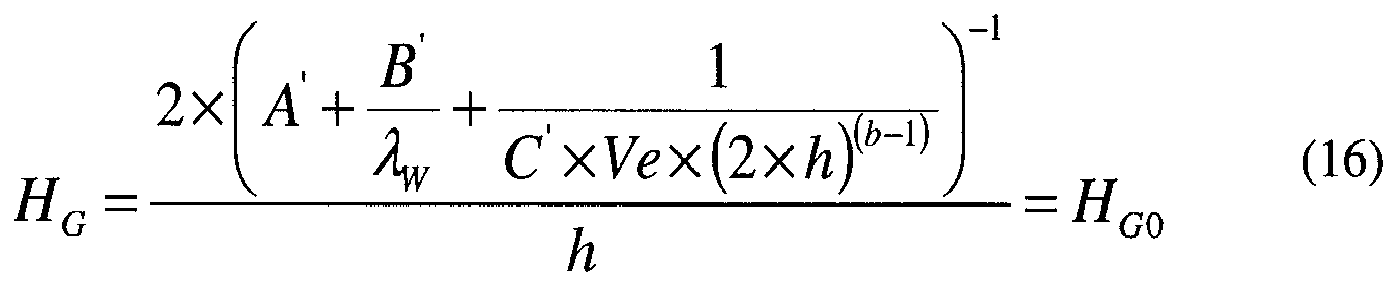

- In the more general case, where h cannot be neglected compared to the channel width w, the equations to be solved by any appropriate conventional methods are:


- The methods disclosed herein allow seamless scale-up of a microreactor processes from lab test or prototyping to production, while keeping the overall performance of the equipment, and particularly the volumetric heat transfer capacity, at the same level. This will lead to a significant reduction in the number of reactors required in parallel, reducing the installation and maintenance cost, and to a significant increase in reliability and predictability in implementing microreaction technology, without requiring full-scale production equipment for reaction and process characterization.
- In some cases, the reduction of the number of reactors in parallel will even make feasible production operations that could not have been envisioned due to the high number of reactor requested without the use of the disclosed methods. Additionally, the disclosed methods provide a way to determine easily the height increase that can be made without making an additional pilot phase to validate the impact of the scale-up, which otherwise would take significant time and effort.
- As the time to market is a key element in the competitiveness of a product, especially in the fine chemical and pharmaceutical industry, the reduced time to market will lead to a significant margin increase.
- Although the examples above all use glass for the lab reactor, other materials having thermal conductivity lower than 3 W/m·K, thought not currently preferred, may be used, such as filled glasses or other composite materials, for example, or even organic materials, where appropriate for the reaction(s) under development.
- The seamless scale-up methods disclosed herein are generally useful in performing any process that involves mixing, separation, extraction, crystallization, precipitation, or otherwise processing fluids or mixtures of fluids, including multiphase mixtures of fluids-and including fluids or mixtures of fluids including multiphase mixtures of fluids that also contain solids-within a microstructure. The processing may include a physical process, a chemical reaction defined as a process that results in the interconversion of organic, inorganic, or both organic and inorganic species, a biochemical process, or any other form of processing. The following nonlimiting list of reactions may be performed with the disclosed methods and/or devices: oxidation; reduction; substitution; elimination; addition; ligand exchange; metal exchange; and ion exchange. More specifically, reactions of any of the following nonlimiting list may be performed with the disclosed methods and/or devices: polymerization; alkylation; dealkylation; nitration; peroxidation; sulfoxidation; epoxidation; ammoxidation; hydrogenation; dehydrogenation; organometallic reactions; precious metal chemistry/ homogeneous catalyst reactions; carbonylation; thiocarbonylation; alkoxylation; halogenation; dehydrohalogenation; dehalogenation; hydroformylation; carboxylation; decarboxylation; amination; arylation; peptide coupling; aldol condensation; cyclocondensation; dehydrocyclization; esterification; amidation; heterocyclic synthesis; dehydration; alcoholysis; hydrolysis; ammonolysis; etherification; enzymatic synthesis; ketalization; saponification; isomerisation; quaternization; formylation; phase transfer reactions; silylations; nitrile synthesis; phosphorylation; ozonolysis; azide chemistry; metathesis; hydrosilylation; coupling reactions; and enzymatic reactions.
Claims (15)
- A method for the seamless scale-up of a continuous-flow microreactor process, to transfer reactions at laboratory-scale to a pilot or production unit, the method comprising the steps of:using a wall material for a lab reactor resulting thermal conductivity across the wall lower than 3 W/m·K, andusing a wall material for a pilot or production reactor resulting in a total thermal conductivity across the wall higher than 5 W/m·K.
- The method according to claim 1, in which the step of using a wall material for the lab reactor further includes using a glass wall material for the lab reactor.
- The method according to claim 1 or 2, in which the step of using a wall material for a pilot or production reactor further includes using a wall material for a pilot or production reactor resulting in a total thermal conductivity across the wall higher than 20W/m·K.
- The method according to any of claims 1-3 , in which the step of using a wall material for a pilot or production reactor further includes using a wall material for a pilot or production reactor resulting in a total thermal conductivity across the wall higher than 100W/m·K.
- The method according to any of claims 1-4, wherein the step of using a wall material for a pilot or production reactor further includes using a ceramic wall material for the pilot or production reactor.
- The method according to claim 5, in which the wall material for the production reactor is silicon carbide.
- The method according to any of claims 1-6, further comprising the steps of:using a velocity in the pilot or production unit that varies less than 10% from a velocity used in the lab test unit, andusing a channel height in the pilot or production unit that selected so as to keep calculated volumetric heat transfer during operation of the pilot orproduction unit within 20% of calculated volumetric heat transfer during operation of the lab test unit.
- The method according to any of claims 1-6, further comprising the steps of:using a velocity in the pilot or production unit that varies less than 10% from a velocity used in the lab test unit, andusing a channel height in the pilot or production unit that selected so as to keep calculated volumetric heat transfer during operation of the pilot or production unit within 10% of calculated volumetric heat transfer during operation of the lab test unit.
- The method according to any of claims 1-6, further comprising the step of:using both an increased velocity and an increased channel height in the pilot or production process, relative to a velocity and a channel height in the lab test process, with the increased velocity and increased height selected such that a process pressure drop and volumetric heat transfer within the pilot or production process are each kept within 20% of a process pressure drop and volumetric heat transfer within the lab test process.
- The method according to any of claims 1-6, further comprising the step of:using a channel height in the pilot or production process greater than a channel height in the lab test process by a factor of between 1.2 and 8.
- The method according to any of claims 1-6, further comprising the step of:using a channel height in the pilot or production process greater than a channel height in the lab test process by a factor of between 1.2 and 3.5.
- The method according to any of claims 1-6, in which the velocity is kept constant, and the height of the channel is determined, in order to keep the volumetric heat transfer properties constant, according to the formula:

- The method according to any of claims 1-6, in which the pressure drop and the volumetric heat transfer properties are kept constant, the channel height and the velocity being selected as calculated according to the simultaneous solution of the following two formulas:


- A system of reactor components for the seamless scale-up of a continuous-flow microreactor process, to transfer reactions characterized or developed at laboratory-scale directly to a pilot or production unit, with limited or no additional experimentation, the system comprising:a plurality of first reaction modules for a lab reactor having a first wall material resulting in a thermal conductivity across the wall of the first reaction modules lower than 3 W/m·K; anda plurality of second reaction modules for a pilot or production reactor having a second wall material resulting in a total thermal conductivity across the wall of the second reaction modules higher than 5 W/m·K.
- The system of reactor components according to claim 14, wherein the second wall material comprises silicon carbide.
Priority Applications (4)
| Application Number | Priority Date | Filing Date | Title |
|---|---|---|---|
| EP11305743A EP2535105A1 (en) | 2011-06-14 | 2011-06-14 | Systems and methods for scale-up of microreactors |
| US14/125,720 US10046295B2 (en) | 2011-06-14 | 2012-06-07 | Methods for scale-up of continuous reactors |
| CN201280029238.6A CN103596676A (en) | 2011-06-14 | 2012-06-07 | Systems and methods for scale-up of continuous flow reactors |
| PCT/US2012/041192 WO2012173848A1 (en) | 2011-06-14 | 2012-06-07 | Systems and methods for scale-up of continuous flow reactors |
Applications Claiming Priority (1)
| Application Number | Priority Date | Filing Date | Title |
|---|---|---|---|
| EP11305743A EP2535105A1 (en) | 2011-06-14 | 2011-06-14 | Systems and methods for scale-up of microreactors |
Publications (1)
| Publication Number | Publication Date |
|---|---|
| EP2535105A1 true EP2535105A1 (en) | 2012-12-19 |
Family
ID=46229963
Family Applications (1)
| Application Number | Title | Priority Date | Filing Date |
|---|---|---|---|
| EP11305743A Withdrawn EP2535105A1 (en) | 2011-06-14 | 2011-06-14 | Systems and methods for scale-up of microreactors |
Country Status (4)
| Country | Link |
|---|---|
| US (1) | US10046295B2 (en) |
| EP (1) | EP2535105A1 (en) |
| CN (1) | CN103596676A (en) |
| WO (1) | WO2012173848A1 (en) |
Cited By (1)
| Publication number | Priority date | Publication date | Assignee | Title |
|---|---|---|---|---|
| US11850564B2 (en) | 2019-08-31 | 2023-12-26 | Corning Incorporated | Heat exchange flow reactor |
Families Citing this family (3)
| Publication number | Priority date | Publication date | Assignee | Title |
|---|---|---|---|---|
| EP2535105A1 (en) * | 2011-06-14 | 2012-12-19 | Corning Incorporated | Systems and methods for scale-up of microreactors |
| AR109884A1 (en) * | 2016-11-02 | 2019-01-30 | Dow Global Technologies Llc | METHODS FOR DESIGNING EXPANDED FLUID CATALYTIC REACTORS |
| US10589242B2 (en) | 2016-11-02 | 2020-03-17 | Dow Global Technologies Llc | Fluid catalytic reactors which include flow directors |
Citations (4)
| Publication number | Priority date | Publication date | Assignee | Title |
|---|---|---|---|---|
| US20060171864A1 (en) * | 2005-01-07 | 2006-08-03 | Philippe Caze | High performance microreaction device |
| US20090120629A1 (en) * | 2005-05-13 | 2009-05-14 | Robert Ashe | Variable heat flux heat exchangers |
| WO2010104597A2 (en) * | 2009-03-13 | 2010-09-16 | President And Fellows Of Harvard College | Scale-up of microfluidic devices |
| WO2010130811A2 (en) * | 2009-05-12 | 2010-11-18 | Lonza Ag | Method of manufacturing a reactor and set of reactors |
Family Cites Families (23)
| Publication number | Priority date | Publication date | Assignee | Title |
|---|---|---|---|---|
| US4892707A (en) * | 1983-07-25 | 1990-01-09 | American Cyanamid Company | Apparatus for the calorimetry of chemical processes |
| US20030118486A1 (en) * | 2000-07-03 | 2003-06-26 | Xeotron Corporation | Fluidic methods and devices for parallel chemical reactions |
| US6955738B2 (en) * | 2002-04-09 | 2005-10-18 | Gyros Ab | Microfluidic devices with new inner surfaces |
| GB0210809D0 (en) * | 2002-05-11 | 2002-06-19 | Univ Durham | Reactor |
| US7007710B2 (en) * | 2003-04-21 | 2006-03-07 | Predicant Biosciences, Inc. | Microfluidic devices and methods |
| US20050072915A1 (en) * | 2003-10-07 | 2005-04-07 | Biospect Inc. | Methods and apparatus for self-optimization of electrospray ionization devices |
| GB0621520D0 (en) * | 2006-10-28 | 2006-12-06 | P2I Ltd | Novel products |
| US7670567B2 (en) * | 2007-01-31 | 2010-03-02 | Stevens Institute Of Technology | Scalable microreactors and methods for using same |
| ATE477220T1 (en) * | 2007-02-28 | 2010-08-15 | Corning Inc | METHOD FOR PRODUCING MICROFLUIDIC DEVICES |
| EP1964816B1 (en) * | 2007-02-28 | 2015-06-03 | Corning Incorporated | Methods for forming compositions containing glass |
| EP2065347A1 (en) * | 2007-11-30 | 2009-06-03 | Corning Incorporated | Durable frit composition and composites and devices comprised thereof |
| JP2010530294A (en) * | 2007-05-18 | 2010-09-09 | コーニング インコーポレイテッド | Glass microfluidic device and method of manufacturing the same |
| DE102007049172A1 (en) * | 2007-10-13 | 2009-04-16 | Micro Systems Engineering Gmbh & Co. Kg | A microreactor and method of making the same and method of making a substrate for a microreactor |
| CN100548468C (en) * | 2007-11-13 | 2009-10-14 | 华东师范大学 | A composite heat exchange filled microreactor |
| PL2222628T3 (en) | 2007-12-20 | 2012-12-31 | Dsm Fine Chemicals Austria Nfg Gmbh & Co Kg | Formation of nitrate esters in microreactors and millireactors using a continuous product extraction in a turbulent flow regime |
| US8414182B2 (en) * | 2008-03-28 | 2013-04-09 | State Of Oregon Acting By And Through The State Board Of Higher Education On Behalf Of Oregon State University | Micromixers for nanomaterial production |
| DE102008048014A1 (en) * | 2008-09-12 | 2010-04-15 | Esk Ceramics Gmbh & Co. Kg | Component of a stack of ceramic plates |
| JP5363932B2 (en) * | 2009-09-28 | 2013-12-11 | 株式会社日立製作所 | Chemical equipment |
| EP2422874A1 (en) * | 2010-08-31 | 2012-02-29 | Corning Incorporated | Fluidic modules with enhanced thermal characteristics |
| EP2535105A1 (en) * | 2011-06-14 | 2012-12-19 | Corning Incorporated | Systems and methods for scale-up of microreactors |
| US20150005429A1 (en) * | 2012-02-13 | 2015-01-01 | Kyowa Chemical Industry Co., Ltd. | Magnesium hydroxide fine particles |
| WO2013126769A1 (en) * | 2012-02-22 | 2013-08-29 | Clingan William Rex | Containment vessel and scale-up method for chemical processes |
| CN104136373A (en) * | 2012-03-26 | 2014-11-05 | 协和化学工业株式会社 | Method for producing hydrotalcite particles |
-
2011
- 2011-06-14 EP EP11305743A patent/EP2535105A1/en not_active Withdrawn
-
2012
- 2012-06-07 CN CN201280029238.6A patent/CN103596676A/en active Pending
- 2012-06-07 US US14/125,720 patent/US10046295B2/en not_active Expired - Fee Related
- 2012-06-07 WO PCT/US2012/041192 patent/WO2012173848A1/en not_active Ceased
Patent Citations (4)
| Publication number | Priority date | Publication date | Assignee | Title |
|---|---|---|---|---|
| US20060171864A1 (en) * | 2005-01-07 | 2006-08-03 | Philippe Caze | High performance microreaction device |
| US20090120629A1 (en) * | 2005-05-13 | 2009-05-14 | Robert Ashe | Variable heat flux heat exchangers |
| WO2010104597A2 (en) * | 2009-03-13 | 2010-09-16 | President And Fellows Of Harvard College | Scale-up of microfluidic devices |
| WO2010130811A2 (en) * | 2009-05-12 | 2010-11-18 | Lonza Ag | Method of manufacturing a reactor and set of reactors |
Non-Patent Citations (6)
| Title |
|---|
| CRAIG HOLVEY: "Characterization of Microreactors with Respect to Pressure Drop, Heat Transfer and Mixing Efficiency", DISSERTATIONS & THESES: THE SCIENCES AND ENGINEERING COLLECTION, 2010, University of Ottawa (Canada), pages 1 - 95, XP055012927, ISBN: 978-0-49-466233-5, Retrieved from the Internet <URL:http://proquest.umi.com/pdf/4eff20bfc4b933bcb3ca44ab1e956829/1322060763//share4/pqimage/pqirs102v/201111230936/03206/31969/out.pdf> [retrieved on 20111123] * |
| KARAGIANNIDIS S ET AL: "Numerical investigation on the start-up of methane-fueled catalytic microreactors", COMBUSTION AND FLAME, ELSEVIER SCIENCE PUBLISHING CO., INC., NEW YORK, NY.; US, vol. 157, no. 7, 1 July 2010 (2010-07-01), pages 1400 - 1413, XP027059301, ISSN: 0010-2180, [retrieved on 20100203] * |
| NORBERT KOCKMANN ET AL: "Scale-up concept of single-channel microreactors from process development to industrial production", CHEMICAL ENGINEERING JOURNAL, vol. 167, no. 2-3, 23 October 2010 (2010-10-23), pages 718 - 726, XP055012571, ISSN: 1385-8947, DOI: 10.1016/j.cej.2010.08.089 * |
| REBROV E ET AL: "Design of a microstructured reactor with integrated heat-exchanger for optimum performance of a highly exothermic reaction", CATALYSIS TODAY, ELSEVIER, NL, vol. 69, no. 1-4, 15 September 2001 (2001-09-15), pages 183 - 192, XP027361177, ISSN: 0920-5861, [retrieved on 20010915] * |
| STUTZ ET AL: "Effects of microreactor wall heat conduction on the reforming process of methane", CHEMICAL ENGINEERING SCIENCE, OXFORD, GB, vol. 60, no. 24, 1 December 2005 (2005-12-01), pages 6983 - 6997, XP005056468, ISSN: 0009-2509, DOI: 10.1016/J.CES.2005.06.012 * |
| THOMAS STIEF ET AL: "NUMERICAL INVESTIGATIONS OF OPTIMAL HEAT CONDUCTIVITY IN MICRO HEAT EXCHANGERS", CHEMICAL ENGINEERING AND TECHNOLOGY, WEINHEIM, DE, vol. 22, no. 4, 26 April 1999 (1999-04-26), pages 297 - 303, XP009077619, ISSN: 0930-7516, DOI: 10.1002/(SICI)1521-4125(199904)22:4<,297::AID-CEAT297>,3.0.CO,2- * |
Cited By (1)
| Publication number | Priority date | Publication date | Assignee | Title |
|---|---|---|---|---|
| US11850564B2 (en) | 2019-08-31 | 2023-12-26 | Corning Incorporated | Heat exchange flow reactor |
Also Published As
| Publication number | Publication date |
|---|---|
| WO2012173848A1 (en) | 2012-12-20 |
| US10046295B2 (en) | 2018-08-14 |
| CN103596676A (en) | 2014-02-19 |
| US20140115871A1 (en) | 2014-05-01 |
Similar Documents
| Publication | Publication Date | Title |
|---|---|---|
| Marsousi et al. | Liquid-liquid extraction of calcium using ionic liquids in spiral microfluidics | |
| Su et al. | An experimental study on the numbering-up of microchannels for liquid mixing | |
| Erickson et al. | Integrated microfluidic devices | |
| Knitter et al. | Ceramic microreactors for heterogeneously catalysed gas-phase reactions | |
| EP2172261B1 (en) | Multiple flow path microfluidic devices | |
| EP2535105A1 (en) | Systems and methods for scale-up of microreactors | |
| TWI425982B (en) | Microstructure heat exchanger | |
| EP3307430B1 (en) | Thermal cross-talk resistant flow reactor | |
| Al-Rawashdeh et al. | Phenylacetylene hydrogenation over [Rh (NBD)(PPh3) 2] BF4 catalyst in a numbered-up microchannels reactor | |
| Serra et al. | Numerical simulation of polymerization in interdigital multilamination micromixers | |
| Lin et al. | Design and evaluation of an easily fabricated micromixer with three-dimensional periodic perturbation | |
| Zhang et al. | Toward a mechanistic understanding of microfluidic droplet-based extraction and separation of lanthanides | |
| Gao et al. | Development of a fast thermal response microfluidic system using liquid metal | |
| McCreedy et al. | Microfabricated reactors for on-chip heterogeneous catalysis | |
| Reichmann et al. | Mixing time scale determination in microchannels using reaction calorimetry | |
| Schwolow et al. | Design and application of a millistructured heat exchanger reactor for an energy-efficient process | |
| Haber et al. | Intensification of highly exothermic fast reaction by multi-injection microstructured reactor | |
| Lavric et al. | Advanced-FlowTM glass reactors for seamless scale-up | |
| Bula et al. | Multichannel quench-flow microreactor chip for parallel reaction monitoring | |
| US20030156995A1 (en) | Microreactor | |
| SG175375A1 (en) | Microreactors with connectors sealed thereon; their manufacturing | |
| Perazzo et al. | A microfluidic approach for flexible and efficient operation of a cross-coupling reactive flow | |
| Togashi et al. | Yield improvement of chemical reactions by using a microreactor and development of a pilot plant using the numbering-up of microreactors | |
| US10183269B2 (en) | Continuous flow reactor with tunable heat transfer capability | |
| Mao et al. | Nanopipette: A high-precision portable programmable instrument for nanoliters to milliliters liquid handling |
Legal Events
| Date | Code | Title | Description |
|---|---|---|---|
| PUAI | Public reference made under article 153(3) epc to a published international application that has entered the european phase |
Free format text: ORIGINAL CODE: 0009012 |
|
| AK | Designated contracting states |
Kind code of ref document: A1 Designated state(s): AL AT BE BG CH CY CZ DE DK EE ES FI FR GB GR HR HU IE IS IT LI LT LU LV MC MK MT NL NO PL PT RO RS SE SI SK SM TR |
|
| AX | Request for extension of the european patent |
Extension state: BA ME |
|
| 17P | Request for examination filed |
Effective date: 20130618 |
|
| RBV | Designated contracting states (corrected) |
Designated state(s): AL AT BE BG CH CY CZ DE DK EE ES FI FR GB GR HR HU IE IS IT LI LT LU LV MC MK MT NL NO PL PT RO RS SE SI SK SM TR |
|
| 17Q | First examination report despatched |
Effective date: 20140818 |
|
| STAA | Information on the status of an ep patent application or granted ep patent |
Free format text: STATUS: THE APPLICATION IS DEEMED TO BE WITHDRAWN |
|
| 18D | Application deemed to be withdrawn |
Effective date: 20150106 |