EP2534450B1 - Angle measurement device and method - Google Patents
Angle measurement device and method Download PDFInfo
- Publication number
- EP2534450B1 EP2534450B1 EP11742614.8A EP11742614A EP2534450B1 EP 2534450 B1 EP2534450 B1 EP 2534450B1 EP 11742614 A EP11742614 A EP 11742614A EP 2534450 B1 EP2534450 B1 EP 2534450B1
- Authority
- EP
- European Patent Office
- Prior art keywords
- sensor
- rotatable member
- metal material
- prosthetic
- amount
- Prior art date
- Legal status (The legal status is an assumption and is not a legal conclusion. Google has not performed a legal analysis and makes no representation as to the accuracy of the status listed.)
- Active
Links
Images


Classifications
-
- A—HUMAN NECESSITIES
- A61—MEDICAL OR VETERINARY SCIENCE; HYGIENE
- A61F—FILTERS IMPLANTABLE INTO BLOOD VESSELS; PROSTHESES; DEVICES PROVIDING PATENCY TO, OR PREVENTING COLLAPSING OF, TUBULAR STRUCTURES OF THE BODY, e.g. STENTS; ORTHOPAEDIC, NURSING OR CONTRACEPTIVE DEVICES; FOMENTATION; TREATMENT OR PROTECTION OF EYES OR EARS; BANDAGES, DRESSINGS OR ABSORBENT PADS; FIRST-AID KITS
- A61F2/00—Filters implantable into blood vessels; Prostheses, i.e. artificial substitutes or replacements for parts of the body; Appliances for connecting them with the body; Devices providing patency to, or preventing collapsing of, tubular structures of the body, e.g. stents
- A61F2/50—Prostheses not implantable in the body
- A61F2/68—Operating or control means
- A61F2/70—Operating or control means electrical
-
- A—HUMAN NECESSITIES
- A61—MEDICAL OR VETERINARY SCIENCE; HYGIENE
- A61F—FILTERS IMPLANTABLE INTO BLOOD VESSELS; PROSTHESES; DEVICES PROVIDING PATENCY TO, OR PREVENTING COLLAPSING OF, TUBULAR STRUCTURES OF THE BODY, e.g. STENTS; ORTHOPAEDIC, NURSING OR CONTRACEPTIVE DEVICES; FOMENTATION; TREATMENT OR PROTECTION OF EYES OR EARS; BANDAGES, DRESSINGS OR ABSORBENT PADS; FIRST-AID KITS
- A61F2/00—Filters implantable into blood vessels; Prostheses, i.e. artificial substitutes or replacements for parts of the body; Appliances for connecting them with the body; Devices providing patency to, or preventing collapsing of, tubular structures of the body, e.g. stents
- A61F2/50—Prostheses not implantable in the body
- A61F2/60—Artificial legs or feet or parts thereof
- A61F2/64—Knee joints
-
- A—HUMAN NECESSITIES
- A61—MEDICAL OR VETERINARY SCIENCE; HYGIENE
- A61F—FILTERS IMPLANTABLE INTO BLOOD VESSELS; PROSTHESES; DEVICES PROVIDING PATENCY TO, OR PREVENTING COLLAPSING OF, TUBULAR STRUCTURES OF THE BODY, e.g. STENTS; ORTHOPAEDIC, NURSING OR CONTRACEPTIVE DEVICES; FOMENTATION; TREATMENT OR PROTECTION OF EYES OR EARS; BANDAGES, DRESSINGS OR ABSORBENT PADS; FIRST-AID KITS
- A61F2/00—Filters implantable into blood vessels; Prostheses, i.e. artificial substitutes or replacements for parts of the body; Appliances for connecting them with the body; Devices providing patency to, or preventing collapsing of, tubular structures of the body, e.g. stents
- A61F2/50—Prostheses not implantable in the body
- A61F2/76—Means for assembling, fitting or testing prostheses, e.g. for measuring or balancing, e.g. alignment means
-
- G—PHYSICS
- G01—MEASURING; TESTING
- G01D—MEASURING NOT SPECIALLY ADAPTED FOR A SPECIFIC VARIABLE; ARRANGEMENTS FOR MEASURING TWO OR MORE VARIABLES NOT COVERED IN A SINGLE OTHER SUBCLASS; TARIFF METERING APPARATUS; MEASURING OR TESTING NOT OTHERWISE PROVIDED FOR
- G01D5/00—Mechanical means for transferring the output of a sensing member; Means for converting the output of a sensing member to another variable where the form or nature of the sensing member does not constrain the means for converting; Transducers not specially adapted for a specific variable
- G01D5/12—Mechanical means for transferring the output of a sensing member; Means for converting the output of a sensing member to another variable where the form or nature of the sensing member does not constrain the means for converting; Transducers not specially adapted for a specific variable using electric or magnetic means
- G01D5/14—Mechanical means for transferring the output of a sensing member; Means for converting the output of a sensing member to another variable where the form or nature of the sensing member does not constrain the means for converting; Transducers not specially adapted for a specific variable using electric or magnetic means influencing the magnitude of a current or voltage
- G01D5/20—Mechanical means for transferring the output of a sensing member; Means for converting the output of a sensing member to another variable where the form or nature of the sensing member does not constrain the means for converting; Transducers not specially adapted for a specific variable using electric or magnetic means influencing the magnitude of a current or voltage by varying inductance, e.g. by a movable armature
- G01D5/2006—Mechanical means for transferring the output of a sensing member; Means for converting the output of a sensing member to another variable where the form or nature of the sensing member does not constrain the means for converting; Transducers not specially adapted for a specific variable using electric or magnetic means influencing the magnitude of a current or voltage by varying inductance, e.g. by a movable armature by influencing the self-induction of one or more coils
- G01D5/2013—Mechanical means for transferring the output of a sensing member; Means for converting the output of a sensing member to another variable where the form or nature of the sensing member does not constrain the means for converting; Transducers not specially adapted for a specific variable using electric or magnetic means influencing the magnitude of a current or voltage by varying inductance, e.g. by a movable armature by influencing the self-induction of one or more coils by a movable ferromagnetic element, e.g. a core
-
- A—HUMAN NECESSITIES
- A61—MEDICAL OR VETERINARY SCIENCE; HYGIENE
- A61F—FILTERS IMPLANTABLE INTO BLOOD VESSELS; PROSTHESES; DEVICES PROVIDING PATENCY TO, OR PREVENTING COLLAPSING OF, TUBULAR STRUCTURES OF THE BODY, e.g. STENTS; ORTHOPAEDIC, NURSING OR CONTRACEPTIVE DEVICES; FOMENTATION; TREATMENT OR PROTECTION OF EYES OR EARS; BANDAGES, DRESSINGS OR ABSORBENT PADS; FIRST-AID KITS
- A61F2/00—Filters implantable into blood vessels; Prostheses, i.e. artificial substitutes or replacements for parts of the body; Appliances for connecting them with the body; Devices providing patency to, or preventing collapsing of, tubular structures of the body, e.g. stents
- A61F2/50—Prostheses not implantable in the body
- A61F2/60—Artificial legs or feet or parts thereof
- A61F2/66—Feet; Ankle joints
- A61F2/6607—Ankle joints
-
- A—HUMAN NECESSITIES
- A61—MEDICAL OR VETERINARY SCIENCE; HYGIENE
- A61F—FILTERS IMPLANTABLE INTO BLOOD VESSELS; PROSTHESES; DEVICES PROVIDING PATENCY TO, OR PREVENTING COLLAPSING OF, TUBULAR STRUCTURES OF THE BODY, e.g. STENTS; ORTHOPAEDIC, NURSING OR CONTRACEPTIVE DEVICES; FOMENTATION; TREATMENT OR PROTECTION OF EYES OR EARS; BANDAGES, DRESSINGS OR ABSORBENT PADS; FIRST-AID KITS
- A61F2/00—Filters implantable into blood vessels; Prostheses, i.e. artificial substitutes or replacements for parts of the body; Appliances for connecting them with the body; Devices providing patency to, or preventing collapsing of, tubular structures of the body, e.g. stents
- A61F2/50—Prostheses not implantable in the body
- A61F2/68—Operating or control means
- A61F2002/6863—Operating or control means magnetic
-
- A—HUMAN NECESSITIES
- A61—MEDICAL OR VETERINARY SCIENCE; HYGIENE
- A61F—FILTERS IMPLANTABLE INTO BLOOD VESSELS; PROSTHESES; DEVICES PROVIDING PATENCY TO, OR PREVENTING COLLAPSING OF, TUBULAR STRUCTURES OF THE BODY, e.g. STENTS; ORTHOPAEDIC, NURSING OR CONTRACEPTIVE DEVICES; FOMENTATION; TREATMENT OR PROTECTION OF EYES OR EARS; BANDAGES, DRESSINGS OR ABSORBENT PADS; FIRST-AID KITS
- A61F2/00—Filters implantable into blood vessels; Prostheses, i.e. artificial substitutes or replacements for parts of the body; Appliances for connecting them with the body; Devices providing patency to, or preventing collapsing of, tubular structures of the body, e.g. stents
- A61F2/50—Prostheses not implantable in the body
- A61F2/68—Operating or control means
- A61F2/70—Operating or control means electrical
- A61F2002/704—Operating or control means electrical computer-controlled, e.g. robotic control
-
- A—HUMAN NECESSITIES
- A61—MEDICAL OR VETERINARY SCIENCE; HYGIENE
- A61F—FILTERS IMPLANTABLE INTO BLOOD VESSELS; PROSTHESES; DEVICES PROVIDING PATENCY TO, OR PREVENTING COLLAPSING OF, TUBULAR STRUCTURES OF THE BODY, e.g. STENTS; ORTHOPAEDIC, NURSING OR CONTRACEPTIVE DEVICES; FOMENTATION; TREATMENT OR PROTECTION OF EYES OR EARS; BANDAGES, DRESSINGS OR ABSORBENT PADS; FIRST-AID KITS
- A61F2/00—Filters implantable into blood vessels; Prostheses, i.e. artificial substitutes or replacements for parts of the body; Appliances for connecting them with the body; Devices providing patency to, or preventing collapsing of, tubular structures of the body, e.g. stents
- A61F2/50—Prostheses not implantable in the body
- A61F2/76—Means for assembling, fitting or testing prostheses, e.g. for measuring or balancing, e.g. alignment means
- A61F2002/7615—Measuring means
- A61F2002/762—Measuring means for measuring dimensions, e.g. a distance
-
- A—HUMAN NECESSITIES
- A61—MEDICAL OR VETERINARY SCIENCE; HYGIENE
- A61F—FILTERS IMPLANTABLE INTO BLOOD VESSELS; PROSTHESES; DEVICES PROVIDING PATENCY TO, OR PREVENTING COLLAPSING OF, TUBULAR STRUCTURES OF THE BODY, e.g. STENTS; ORTHOPAEDIC, NURSING OR CONTRACEPTIVE DEVICES; FOMENTATION; TREATMENT OR PROTECTION OF EYES OR EARS; BANDAGES, DRESSINGS OR ABSORBENT PADS; FIRST-AID KITS
- A61F2/00—Filters implantable into blood vessels; Prostheses, i.e. artificial substitutes or replacements for parts of the body; Appliances for connecting them with the body; Devices providing patency to, or preventing collapsing of, tubular structures of the body, e.g. stents
- A61F2/50—Prostheses not implantable in the body
- A61F2/76—Means for assembling, fitting or testing prostheses, e.g. for measuring or balancing, e.g. alignment means
- A61F2002/7615—Measuring means
- A61F2002/7625—Measuring means for measuring angular position
-
- G—PHYSICS
- G01—MEASURING; TESTING
- G01D—MEASURING NOT SPECIALLY ADAPTED FOR A SPECIFIC VARIABLE; ARRANGEMENTS FOR MEASURING TWO OR MORE VARIABLES NOT COVERED IN A SINGLE OTHER SUBCLASS; TARIFF METERING APPARATUS; MEASURING OR TESTING NOT OTHERWISE PROVIDED FOR
- G01D2205/00—Indexing scheme relating to details of means for transferring or converting the output of a sensing member
- G01D2205/70—Position sensors comprising a moving target with particular shapes, e.g. of soft magnetic targets
- G01D2205/77—Specific profiles
- G01D2205/775—Tapered profiles
Definitions
- This disclosure relates to sensors for determining an absolute angle of rotational objects in a prosthetic joint.
- Modern, computer controlled prosthetic devices have many advantages over conventional prosthetic devices.
- computer controlled prosthetic devices can allow the amputees to walk with limited fear of stumbling or falling, allow amputees to lead a more active lifestyle, and improve the likelihood that amputees can realize their full economic potential. This is especially beneficial for the thousands of new amputees each year and the millions of existing amputees.
- a lower limb prosthesis comprising a knee flexion control device arranged to resist flexion at the knee joint hydraulically is known from GB 2 367 753 A , wherein the resistance to flexion is arranged by programmable electronic control means via a rotary valve and a stepper motor.
- US 6 113 642 A discloses a computer controlled hydraulic resistance device for apparatus such as a prosthetic knee for above knee amputees, including a two stage pilot operated solenoid valve connected to control the flow of hydraulic fluid to and from a hydraulic actuator which applies resistance to the prosthetic knee or other apparatus through a coupling.
- the present invention provides a sensor device for an artificial joint and a method for determining an angle of a rotatable member in a prosthetic joint as featured in the independent claims. Preferred embodiments of the present invention are described in the dependent claims.
- the present invention relates to a sensor device for determining an absolute angle of a prosthetic joint, and which is resistant to environmental elements and has a reduced power draw.
- the sensor device of the present invention includes an inductive proximity sensor (hereinafter also simply referred to as the inductive sensor) and a rotatable member including a metal material.
- the inductive sensor detects an amount of the metal material in a proximate location to the inductive sensor.
- a gap between the metal material and the inductive sensor increases or decreases.
- This increase or decrease in the gap corresponds to an amount of metal material in the proximate location of the inductive sensor.
- the amount of metal material in the proximate location corresponds to an angle of the rotatable member and/or the prosthetic joint based on a monotonic function.
- the monotonic function can be, for example, an absolute monotonic function or a relative monotonic function.
- the inductive sensor can detect the amount of metal material in the proximate location to determine the angle of the rotatable member and subsequently the angle of the prosthetic device.
- an absolute monotonic function is used such as when the sensor device is an absolute sensor device, no memory is used to remember a previous position and to calculate a current position based on a differential.
- An absolute sensor device reduces power consumption by having fewer components.
- the inductive sensor can be better sealed to protect the inductive sensor and/or the metal material from the environmental elements. This can increase longevity of the inductive sensor and/or the metal material. In addition, it may allow the amputee to perform activities which may have previously been limited using other sensing modalities due to the fear of environmental exposure to the inductive sensor and/or the metal material such as construction, hiking, and various sports, especially those involving water.
- the metal material can include a non-ferrous metal material.
- the use of the non-ferrous metal material is advantageous in that non-ferrous metal material can be lighter than ferrous metal material.
- the weight of the prosthetic joint can be reduced.
- the reduced weight of the prosthetic joint can allow smaller amputees to use prosthetic devices. In can also allow a person in general to expend less energy using the prosthetic device devices.
- the inductive sensor can utilize less power than other conventional sensors. This reduction in power consumption can translate to a smaller battery size required for the prosthetic device. This can again reduce the weight of the prosthetic device.
- the present invention relates to a sensor device according to claim 1.
- the present invention relates to a sensor device for a prosthetic joint the sensor device including a rotatable member, a non-ferrous metal material connected to the rotatable member, and an inductive proximity sensor configured to detect an amount of the non-ferrous metal material in a spherical shape based on a location of the inductive sensor, and to generate an output corresponding to an angle of the rotatable member based on the amount of the metal material in the spherical shape, wherein the amount of the non-ferrous metal material in the spherical shape corresponds to the angle of the rotatable member based on an absolute or relative monotonic function.
- the present invention is a method according to claim 9.
- a prosthetic device 100 can include, for example, a prosthetic joint 102 and a frame 104.
- FIG. 2 depicts a cross-section of the prosthetic device 100 along the line A-A.
- the prosthetic joint 102 can be seen more clearly in FIG. 3 , which is a close-up sectional view of portion B in FIG. 2 .
- the prosthetic joint 102 includes portions of the frame 104.
- the prosthetic joint 102 also includes, a rotatable member 106, a rotatable member 108 coupled to the rotatable member 106 such that rotation of the rotatable member 106 also rotates the rotatable member 108, and a metal portion 110 at an end of the rotatable member 106.
- the metal portion 110 can include, for example, a metal material and form, for example, a rotatable cam.
- the rotatable member 106 can rotate about a pivot 1 12 to move the prosthetic joint 102 into a different position.
- the prosthetic joint 102 and the rotatable member 106 are in a first position.
- FIG. 4 depicts the prosthetic joint 102 in a second position different than the first position.
- FIG. 5 depicts a cross-section of the prosthetic device 100 at the section C-C, while FIG. 6 depicts the section D indicated in FIG. 5 .
- the prosthetic joint 102 and the rotatable member 106 have rotated onto the second position different from the first position.
- the prosthetic device 100 includes a sensor 114 to determine the angle of the rotatable member 106 with respect to the prosthetic joint 102.
- the sensor 114 is a proximity sensor which detects an amount of metal material in a proximate location to the sensor 114 and outputs metal material data regarding the amount of metal material in the proximate location.
- the inductive proximity sensor can utilize 6 ⁇ amps as opposed to some sensors which utilize thousands or even millions of ⁇ amps. This can significantly reduce a size of the battery required to operate the prosthetic device 100. A reduction in the battery size correspondingly reduces a size and weight of the prosthetic device. This allows for a more diverse type of amputee population to use the prosthetic device 100.
- the sensor 114 can include, for example, a housing 116 and wires 118.
- the housing 116 can protect, for example the components of the sensor 114.
- the housing 116 can also form an environment seal to further protect the sensor 114 from damage.
- the wires 118 can transmit an output of the sensor 114 to a processor or other device which can analyze and/or manipulate the output of the sensor 114.
- the sensor 114 can include, for example, a processor 126 and a memory 128 as shown in FIG. 9 .
- the processor 126 can analyze the metal material data detected by the sensor 114, while the memory 128 can store information which can be used to analyze and/or manipulate the metal material data of the sensor 114.
- the processor 126 and the memory 128 are external to the sensor 114 as shown in FIG. 10 .
- the sensor 114 can output the metal material data and the processor 126 can analyze and/or manipulate the metal material data using information stored in the memory 128.
- the senor 114, the metal portion 110, the rotatable member 106, and/or the processor 126 can form a sensor device 130.
- the sensor device 130 can be part of the prosthetic joint 102 and/or the prosthetic device 100.
- the sensor device 130 and its components can be used to determine the angle of the rotatable member 106 and subsequently the angle of the prosthetic joint 102.
- the rotation of the rotatable member 106 increases or decreases a distance of a gap 132 between the sensor 114 and the metal portion 110.
- the gap 132 has a distance of d1
- the gap 132 has a distance of d2, which is greater than d1.
- the rotation of the rotatable member 106 increased the distance of the gap 132 between the sensor 114 and the metal portion 110.
- the increase or decrease of the distance of the gap 132 between the sensor 114 and the metal portion 110 increases or decreases an amount of metal material in the proximate location to the sensor 114.
- the amount of metal material in the proximate location to the sensor 114 correlates with the angle of the rotatable member 106 in an absolute monotonic function.
- the sensor 114 can be sealed or coated to protect the sensor 114 and/or the metal portion 110 from the environmental elements. Furthermore, as noted above, the housing 116 ( FIGS. 7 and 8 ) can be environmentally sealed. This can increase a longevity of the sensor 114 and/or the metal portion 110. In additional, the protective seal or coating may allow the amputee to perform activities which may have previously been limited due to the fear of environmental exposure to the sensor 114 and/or the metal portion 110 such as construction, hiking, outings near water, and various sports.
- the sensor 114 can determine the angle of the rotatable member 106 ( FIG. 3 ) and subsequently the angle of the prosthetic joint 102 ( FIG. 3 ) based on the metal material data indicating an amount of metal material detected by the sensor 114 in the proximate location. Otherwise, if the processor 126 is external to the sensor 114 as shown in FIG. 10 , the processor 126 can receive the metal material data from the sensor 114 indicating an amount of metal material detected by the sensor 114. The processor 126 can determine based on the metal material data, the angle of the rotatable member 106 ( FIG. 3 ) and subsequently the angle of the prosthetic joint 102 ( FIG. 3 ).
- the counts on the Y-axis indicate an amount of metal material detected by the sensor 114, while the angle on the X-axis indicates an angle of the rotatable member 106.
- the amount of the metal material detected by the sensor 114 can correspond to the angle of the rotatable member 106 based on an absolute monotonic function as indicated by a curve 120.
- a curve 122 and a curve 124 are depicted to indicate a standard deviation of the values of the curve 120. The curve 122 and the curve 124 can be used to determine error thresholds for the data detected by the sensor 114.
- the monotonic function in FIG. 12 is non-linear, the monotonic function can also be linear.
- the angle of the rotatable member 106 is the angle between the rotatable member 106 and the frame 104. In another embodiment, the angle of the rotatable member 106 indicates an angle of rotation between two positions. In yet another embodiment, the angle of the rotatable member 106 indicates an angle between a predetermined position and a current position of the rotatable member 106.
- an absolute monotonic function is used, a relative monotonic function could also be used.
- the processor 126 can utilize the graph shown on FIG. 12 to determine the angle of the rotatable member 106 and subsequently the angle of the prosthetic joint 102.
- the information presented in the graph in FIG. 12 can also be contained in a look-up table stored in the memory 128.
- the processor in the sensor 114 or an external processor can utilize the look-up table to determine the angle of the prosthetic joint 102.
- the sensor 114 can function as an absolute position sensor. Thus, when the sensor 114 and/or the prosthetic device 100 is activated, the sensor 114 and/or the processor 126 can immediately or substantially immediately determine an angle of the rotatable member 106 and/or the prosthetic joint 102.
- the rotatable member 106 and/or the prosthetic joint 102 does not have to move through any number of positions (like a repeating vernier scale), or store in memory a previous position and calculate movement from the previous position to determine the current angle of the rotatable member 106 and/or the prosthetic joint 102.
- the prosthetic device 100 is shown as a prosthetic leg, the prosthetic device 100 can also be a prosthetic arm or other prosthetic body part. Thus, some or all of the components of the sensor device 130 can be part of the prosthetic arm or other prosthetic body part.
- the prosthetic joint 102 is shown as a prosthetic knee, the prosthetic joint 102 can also be, for example, a prosthetic ankle, a prosthetic elbow, a prosthetic wrist, or other type of joints which may require the use of prosthesis.
- some or all of the components of the sensor device 130 can be part of the prosthetic ankle, the prosthetic elbow, the prosthetic wrist, or other type of joints which may require the use of prosthesis.
- the sensor device 130 can also be used for artificial joints in addition to prosthetic joints, such as orthotic joints.
- the sensor device 130 can also detect a relative angle of the rotational objects in addition to the absolute angle.
- the proximate location for the sensor 114 can be, for example, a spherical shape.
- the spherical shape can be based on the location of the sensor 114.
- the metal portion 110 can include, for example, a non-ferrous metal material or a combination of ferrous and non-ferrous metal material.
- the non-ferrous metal material can be, for example, aluminum. Since non-ferrous metal such as aluminum can be lighter than ferrous material, this can reduce a weight of the prosthetic joint 102 and/or the prosthetic device 100. The reduced weight of the prosthetic joint 102 and/or the prosthetic device 100 can allow smaller amputees to use the prosthetic joint 102 and/or the prosthetic device 100.
- the present invention is a process as shown in FIG. 13 .
- an amount of metal material in a proximate location is detected using an inductive sensor.
- the sensor 114 can detect an amount of metal portion 110 is present in a proximate location of the sensor 114.
- the sensor 114 is an inductive proximity sensor.
- an output corresponding to an angle of the rotatable member based on the amount of the metal material in the proximate location is output using the inductive proximity sensor.
- the sensor 114 can generate metal material data indicating an amount of the metal portion 110 is present in the proximate location.
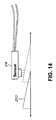
- the metal portion 110 can form, for example, a cam as shown in FIG. 3 , a metal portion 210 forming a wedge, or a metal portion 310 forming variable profile unit as shown in FIG. 14 and FIGS. 15 - 17 , respectively, can be used.
- the sensor 114 can detect a translational position of an object.
- the metal portion 210 forms a wedge, and the sensor 114 can determine an amount of metal material in the proximate location of the sensor 114.
- an amount of metal material increases.
- the amount of the metal material in the proximate location corresponds to the linear location of the metal portion 210.
- the amount of the metal material in the proximate location corresponds to the linear location of the metal portion 210 based on a monotonic function and such relationship can be stored, for example, in the memory 128 ( FIG. 11 ).
- the sensor 114 can determine a translational location of the metal portion 210.
- the sensor 114 can detect an amount of rotation of the metal portion 310.
- the metal portion 310 forms a variable profile unit, and the sensor 114 can determine an amount of metal material in the proximate location of the sensor 114.
- the metal portion 310 includes a thin portion 134 with a thickness of t2 and a thick portion 136 with a thickness of t1.
- the thickness t1 is greater than the thickness t2.
- FIGS. 16 and 17 For example, as the metal portion 310 is rotated, an amount of metal material in the proximate location of the sensor 114 increases as shown in FIGS. 16 and 17 .
- the thin portion 134 is facing the sensor 114
- the thick portion 136 is facing the sensor 114.
- the amount of the metal material in the proximate location corresponds to the rotation of the metal portion 210 based on a function and such relationship can be stored, for example, in the memory 128 ( FIG. 11 ).
- the sensor 114 can determine a rotation of the metal portion 210.
- aspects and implementations of the present disclosure may be useful for analysis of a variety of actions, activities, events, and phenomena.
- embodiments may be used to analyze any rotation motion. Such information may be used to detect or predict activity that approaches the known limits of a system or device to avoid extension beyond said limits. Such information may also be used to determine appropriate action in response to adjust at least one of the factors contributing to rotational action.
- embodiments may be used to collect information about activity and environment during a gait cycle. For example, the rotation of portions of a leg, knee, arm, elbow, or other articulated member may be sensed and utilized in a system or device to track, react to, or respond to such readings. Responses may include the application of settings in a prosthetic knee to facilitate improved mobility of a user. Other joints and parts of the body may be benefited by embodiments of the present disclosure.
- DSP digital signal processor
- ASIC application specific integrated circuit
- FPGA field programmable gate array
- a general purpose processor may be a microprocessor, but in the alternative, the processor may be any conventional processor, controller, microcontroller, or state machine.
- a processor may also be implemented as a combination of computing devices, e.g., a combination of a DSP and a microprocessor, a plurality of microprocessors, one or more microprocessors in conjunction with a DSP core, or any other such configuration.
- a software module may reside in RAM memory, flash memory, ROM memory, EPROM memory, EEPROM memory, registers, hard disk, a removable disk, a CD-ROM, or any other form of storage medium known in the art.
- An exemplary storage medium is coupled to the processor such that the processor can read information from, and write information to, the storage medium.
- the storage medium may be integral to the processor.
- the processor and the storage medium may reside in an Application Specific Integrated Circuit (ASIC).
- the ASIC may reside in a wireless modem.
- the processor and the storage medium may reside as discrete components in the wireless modem.
Description
- This disclosure relates to sensors for determining an absolute angle of rotational objects in a prosthetic joint.
- Modern, computer controlled prosthetic devices have many advantages over conventional prosthetic devices. For example, computer controlled prosthetic devices can allow the amputees to walk with limited fear of stumbling or falling, allow amputees to lead a more active lifestyle, and improve the likelihood that amputees can realize their full economic potential. This is especially beneficial for the thousands of new amputees each year and the millions of existing amputees.
- However, modern, computer controlled prosthetic devices are limited in some aspects due to the number of electrical parts. These limitations can include, for example, the shortened lifespan of its electrical parts, such as a sensor to measure an angle of a prosthetic joint, due to dust, moisture, or other environmental elements. The dust, moisture, and other environmental elements can also limit, for example, the type of activities that an amputee can perform while using the modern, computer controlled prosthetic devices. However, computer control of a joint during normal ambulation, or gait, requires robust and accurate sensors to provide input to the control strategy. These sensors could detect information such as joint position, knee angle, forces, weight bearing forces, ankle torque, knee torque, velocity, or acceleration.
- Other limitations with the sheer number of electrical parts include the power draw. Naturally, increasing the number of electrical parts correspondingly increases the power required to operate the prosthetic device. One method to support this large increase in power draw is to increase the battery size. However, increasing the battery size increases the size and weight of the prosthetic device. This is undesirable since the prosthetic device should be the same length as the intact limb of the amputee. Thus, larger prosthetic devices may be undesirable for amputees that are shorter in height, especially children. Furthermore, the added weight can hinder the movements of the amputee, regardless of height. However, children may be especially impacted as they will not be as muscularly developed and may not be adept at handling the extra weight of the larger battery. Thus, any decrease in power consumption is beneficial to amputees because of the corresponding reduction in the size and weight of the prosthetic device.
- Thus, there is a need for a sensor device for determining an absolute angle of a prosthetic joint, and which is resistant to environmental elements and has a reduced power draw.
- A lower limb prosthesis comprising a knee flexion control device arranged to resist flexion at the knee joint hydraulically is known from
GB 2 367 753 AUS 6 113 642 A discloses a computer controlled hydraulic resistance device for apparatus such as a prosthetic knee for above knee amputees, including a two stage pilot operated solenoid valve connected to control the flow of hydraulic fluid to and from a hydraulic actuator which applies resistance to the prosthetic knee or other apparatus through a coupling. - The present invention provides a sensor device for an artificial joint and a method for determining an angle of a rotatable member in a prosthetic joint as featured in the independent claims. Preferred embodiments of the present invention are described in the dependent claims. In particular, the present invention relates to a sensor device for determining an absolute angle of a prosthetic joint, and which is resistant to environmental elements and has a reduced power draw. The sensor device of the present invention includes an inductive proximity sensor (hereinafter also simply referred to as the inductive sensor) and a rotatable member including a metal material. The inductive sensor detects an amount of the metal material in a proximate location to the inductive sensor.
- As the rotatable member is rotated, a gap between the metal material and the inductive sensor increases or decreases. This increase or decrease in the gap corresponds to an amount of metal material in the proximate location of the inductive sensor. The amount of metal material in the proximate location corresponds to an angle of the rotatable member and/or the prosthetic joint based on a monotonic function. The monotonic function can be, for example, an absolute monotonic function or a relative monotonic function. Thus, the inductive sensor can detect the amount of metal material in the proximate location to determine the angle of the rotatable member and subsequently the angle of the prosthetic device. When an absolute monotonic function is used such as when the sensor device is an absolute sensor device, no memory is used to remember a previous position and to calculate a current position based on a differential. An absolute sensor device reduces power consumption by having fewer components.
- Since the metal material does not contact the inductive sensor, the inductive sensor can be better sealed to protect the inductive sensor and/or the metal material from the environmental elements. This can increase longevity of the inductive sensor and/or the metal material. In addition, it may allow the amputee to perform activities which may have previously been limited using other sensing modalities due to the fear of environmental exposure to the inductive sensor and/or the metal material such as construction, hiking, and various sports, especially those involving water.
- The metal material can include a non-ferrous metal material. The use of the non-ferrous metal material is advantageous in that non-ferrous metal material can be lighter than ferrous metal material. Thus, the weight of the prosthetic joint can be reduced. The reduced weight of the prosthetic joint can allow smaller amputees to use prosthetic devices. In can also allow a person in general to expend less energy using the prosthetic device devices.
- Furthermore, the inductive sensor can utilize less power than other conventional sensors. This reduction in power consumption can translate to a smaller battery size required for the prosthetic device. This can again reduce the weight of the prosthetic device.
- In a first aspect the present invention relates to a sensor device according to
claim 1. - In one embodiment, the present invention relates to a sensor device for a prosthetic joint the sensor device including a rotatable member, a non-ferrous metal material connected to the rotatable member, and an inductive proximity sensor configured to detect an amount of the non-ferrous metal material in a spherical shape based on a location of the inductive sensor, and to generate an output corresponding to an angle of the rotatable member based on the amount of the metal material in the spherical shape, wherein the amount of the non-ferrous metal material in the spherical shape corresponds to the angle of the rotatable member based on an absolute or relative monotonic function.
- In a second aspect, the present invention is a method according to claim 9.
- The above-mentioned features and objects of the present disclosure will become more apparent with reference to the following description taken in conjunction with the accompanying drawings wherein like reference numerals denote like elements and in which:
-
FIG. 1 depicts a frame of a prosthetic device comprising an embodiment of the present invention; -
FIG. 2 is a sectional view of a prosthetic device comprising an embodiment of the present invention; -
FIG. 3 depicts a prosthetic joint comprising an embodiment of the present invention; -
FIG. 4 depicts a prosthetic device comprising an embodiment of the present invention rotated with respect toFIG. 1 ; -
FIG. 5 is a sectional view of a prosthetic device comprising an embodiment of the present invention rotated with respect toFIG. 2 ; -
FIG. 6 depicts a prosthetic joint comprising an embodiment of the present invention rotated with respect toFIG. 3 ; -
FIG. 7 depicts an inductive sensor according to an embodiment of the present invention; -
FIG. 8 is a perspective view of an inductive sensor according to an embodiment of the present invention; -
FIG. 9 depicts a sensor including a processor and a memory according to an embodiment of the present invention; -
FIG. 10 is a box diagram of a sensor, a processor, and a memory according to an embodiment of the present invention; -
FIG. 11 is a box diagram of a sensor device according to an embodiment of the present invention; -
FIG. 12 is a graph of prosthetic joint angle versus digital step count according to an embodiment of the present invention; -
FIG. 13 depicts a process according to an embodiment of the present invention; -
FIG. 14 depicts an inductive sensor detecting linear motion according to an embodiment of the present invention; -
FIG. 15 depicts an inductive sensor and a variable profile unit according to an embodiment of the present invention; -
FIG. 16 depicts an inductive sensor and a variable profile unit according to an embodiment of the present invention; and -
FIG. 17 depicts an inductive sensor and a variable profile unit according to an embodiment of the present invention. - The detailed description of exemplary embodiments herein makes reference to the accompanying drawings and pictures, which show the exemplary embodiment by way of illustration and its best mode. While these exemplary embodiments are described in sufficient detail to enable those skilled in the art to practice the invention, it should be understood that other embodiments may be realized and that logical and mechanical changes may be made without departing from the scope of the invention. Thus, the detailed description herein is presented for purposes of illustration only and not of limitation. For example, the steps recited in any of the method or process descriptions may be executed in any order and are not limited to the order presented. Moreover, any of the functions or steps may be outsourced to or performed by one or more third parties. Furthermore, any reference to singular includes plural embodiments, and any reference to more than one component may include a singular embodiment.
- As shown in
FIGS. 1 and 2 , aprosthetic device 100 can include, for example, a prosthetic joint 102 and aframe 104.FIG. 2 depicts a cross-section of theprosthetic device 100 along the line A-A. The prosthetic joint 102 can be seen more clearly inFIG. 3 , which is a close-up sectional view of portion B inFIG. 2 . As seen inFIG. 3 , the prosthetic joint 102 includes portions of theframe 104. The prosthetic joint 102 also includes, arotatable member 106, arotatable member 108 coupled to therotatable member 106 such that rotation of therotatable member 106 also rotates therotatable member 108, and ametal portion 110 at an end of therotatable member 106. Themetal portion 110 can include, for example, a metal material and form, for example, a rotatable cam. - The
rotatable member 106 can rotate about apivot 1 12 to move the prosthetic joint 102 into a different position. For example, inFIGS. 1 - 3 , the prosthetic joint 102 and therotatable member 106 are in a first position. However,FIG. 4 depicts the prosthetic joint 102 in a second position different than the first position.FIG. 5 depicts a cross-section of theprosthetic device 100 at the section C-C, whileFIG. 6 depicts the section D indicated inFIG. 5 . As seen inFIGS. 4 - 6 , the prosthetic joint 102 and therotatable member 106 have rotated onto the second position different from the first position. - Referring back to
FIG. 3 , theprosthetic device 100 includes asensor 114 to determine the angle of therotatable member 106 with respect to the prosthetic joint 102. Thesensor 114 is a proximity sensor which detects an amount of metal material in a proximate location to thesensor 114 and outputs metal material data regarding the amount of metal material in the proximate location. - One benefit of using an inductive proximity sensor is the relatively low current draw. For example, the inductive sensor can utilize 6 µamps as opposed to some sensors which utilize thousands or even millions of µamps. This can significantly reduce a size of the battery required to operate the
prosthetic device 100. A reduction in the battery size correspondingly reduces a size and weight of the prosthetic device. This allows for a more diverse type of amputee population to use theprosthetic device 100. - As seen in
FIGS. 7 and 8 , thesensor 114 can include, for example, ahousing 116 andwires 118. Thehousing 116 can protect, for example the components of thesensor 114. Thehousing 116 can also form an environment seal to further protect thesensor 114 from damage. Thewires 118 can transmit an output of thesensor 114 to a processor or other device which can analyze and/or manipulate the output of thesensor 114. In one embodiment, thesensor 114 can include, for example, aprocessor 126 and amemory 128 as shown inFIG. 9 . Theprocessor 126 can analyze the metal material data detected by thesensor 114, while thememory 128 can store information which can be used to analyze and/or manipulate the metal material data of thesensor 114. - In another embodiment, the
processor 126 and thememory 128 are external to thesensor 114 as shown inFIG. 10 . In which case, thesensor 114 can output the metal material data and theprocessor 126 can analyze and/or manipulate the metal material data using information stored in thememory 128. - In one embodiment, as seen in
FIG. 11 , thesensor 114, themetal portion 110, therotatable member 106, and/or theprocessor 126 can form asensor device 130. Thesensor device 130 can be part of the prosthetic joint 102 and/or theprosthetic device 100. Thesensor device 130 and its components can be used to determine the angle of therotatable member 106 and subsequently the angle of the prosthetic joint 102. - For example, as seen in
FIG. 3 andFIG. 6 , the rotation of therotatable member 106 increases or decreases a distance of agap 132 between thesensor 114 and themetal portion 110. InFIG. 3 , thegap 132 has a distance of d1, while inFIG. 6 , thegap 132 has a distance of d2, which is greater than d1. Thus, the rotation of therotatable member 106 increased the distance of thegap 132 between thesensor 114 and themetal portion 110. The increase or decrease of the distance of thegap 132 between thesensor 114 and themetal portion 110 increases or decreases an amount of metal material in the proximate location to thesensor 114. Furthermore, the amount of metal material in the proximate location to thesensor 114 correlates with the angle of therotatable member 106 in an absolute monotonic function. - Since the
metal portion 110 does not contact thesensor 114, thesensor 114 can be sealed or coated to protect thesensor 114 and/or themetal portion 110 from the environmental elements. Furthermore, as noted above, the housing 116 (FIGS. 7 and 8 ) can be environmentally sealed. This can increase a longevity of thesensor 114 and/or themetal portion 110. In additional, the protective seal or coating may allow the amputee to perform activities which may have previously been limited due to the fear of environmental exposure to thesensor 114 and/or themetal portion 110 such as construction, hiking, outings near water, and various sports. - If the
sensor 114 includes theprocessor 126 as shown inFIG. 9 , then thesensor 114 can determine the angle of the rotatable member 106 (FIG. 3 ) and subsequently the angle of the prosthetic joint 102 (FIG. 3 ) based on the metal material data indicating an amount of metal material detected by thesensor 114 in the proximate location. Otherwise, if theprocessor 126 is external to thesensor 114 as shown inFIG. 10 , theprocessor 126 can receive the metal material data from thesensor 114 indicating an amount of metal material detected by thesensor 114. Theprocessor 126 can determine based on the metal material data, the angle of the rotatable member 106 (FIG. 3 ) and subsequently the angle of the prosthetic joint 102 (FIG. 3 ). - This can be seen, for example, in the graph shown on
FIG. 12 which can be stored in thememory 128. The counts on the Y-axis indicate an amount of metal material detected by thesensor 114, while the angle on the X-axis indicates an angle of therotatable member 106. As seen inFIG. 12 , the amount of the metal material detected by thesensor 114 can correspond to the angle of therotatable member 106 based on an absolute monotonic function as indicated by acurve 120. Acurve 122 and acurve 124 are depicted to indicate a standard deviation of the values of thecurve 120. Thecurve 122 and thecurve 124 can be used to determine error thresholds for the data detected by thesensor 114. - Although the monotonic function in
FIG. 12 is non-linear, the monotonic function can also be linear. In one embodiment, the angle of therotatable member 106 is the angle between therotatable member 106 and theframe 104. In another embodiment, the angle of therotatable member 106 indicates an angle of rotation between two positions. In yet another embodiment, the angle of therotatable member 106 indicates an angle between a predetermined position and a current position of therotatable member 106. In addition, although an absolute monotonic function is used, a relative monotonic function could also be used. - Thus, the processor 126 (
FIG. 11 ) can utilize the graph shown onFIG. 12 to determine the angle of therotatable member 106 and subsequently the angle of the prosthetic joint 102. Alternatively, the information presented in the graph inFIG. 12 can also be contained in a look-up table stored in thememory 128. In such a case, the processor in thesensor 114 or an external processor can utilize the look-up table to determine the angle of the prosthetic joint 102. In one embodiment, thesensor 114 can function as an absolute position sensor. Thus, when thesensor 114 and/or theprosthetic device 100 is activated, thesensor 114 and/or theprocessor 126 can immediately or substantially immediately determine an angle of therotatable member 106 and/or the prosthetic joint 102. Thus, therotatable member 106 and/or the prosthetic joint 102 does not have to move through any number of positions (like a repeating vernier scale), or store in memory a previous position and calculate movement from the previous position to determine the current angle of therotatable member 106 and/or the prosthetic joint 102. - Although the
prosthetic device 100 is shown as a prosthetic leg, theprosthetic device 100 can also be a prosthetic arm or other prosthetic body part. Thus, some or all of the components of thesensor device 130 can be part of the prosthetic arm or other prosthetic body part. Likewise, although the prosthetic joint 102 is shown as a prosthetic knee, the prosthetic joint 102 can also be, for example, a prosthetic ankle, a prosthetic elbow, a prosthetic wrist, or other type of joints which may require the use of prosthesis. Thus, some or all of the components of thesensor device 130 can be part of the prosthetic ankle, the prosthetic elbow, the prosthetic wrist, or other type of joints which may require the use of prosthesis. In addition, thesensor device 130 can also be used for artificial joints in addition to prosthetic joints, such as orthotic joints. Furthermore, thesensor device 130 can also detect a relative angle of the rotational objects in addition to the absolute angle. - In detecting the metal material, the proximate location for the
sensor 114 can be, for example, a spherical shape. The spherical shape can be based on the location of thesensor 114. Furthermore themetal portion 110 can include, for example, a non-ferrous metal material or a combination of ferrous and non-ferrous metal material. The non-ferrous metal material can be, for example, aluminum. Since non-ferrous metal such as aluminum can be lighter than ferrous material, this can reduce a weight of the prosthetic joint 102 and/or theprosthetic device 100. The reduced weight of the prosthetic joint 102 and/or theprosthetic device 100 can allow smaller amputees to use the prosthetic joint 102 and/or theprosthetic device 100. - The present invention is a process as shown in
FIG. 13 . In Step S1302, an amount of metal material in a proximate location is detected using an inductive sensor. For example, thesensor 114 can detect an amount ofmetal portion 110 is present in a proximate location of thesensor 114. Thesensor 114 is an inductive proximity sensor. In Step S1304, an output corresponding to an angle of the rotatable member based on the amount of the metal material in the proximate location is output using the inductive proximity sensor. For example, thesensor 114 can generate metal material data indicating an amount of themetal portion 110 is present in the proximate location. - Although the
metal portion 110 can form, for example, a cam as shown inFIG. 3 , ametal portion 210 forming a wedge, or ametal portion 310 forming variable profile unit as shown inFIG. 14 and FIGS. 15 - 17 , respectively, can be used. - In
FIG. 14 , thesensor 114 can detect a translational position of an object. For example, inFIG. 14 , themetal portion 210 forms a wedge, and thesensor 114 can determine an amount of metal material in the proximate location of thesensor 114. As themetal portion 210 slides past thesensor 114, an amount of metal material increases. Provided that themetal portion 210 does not slide past a point where there is a peak amount of the metal material, the amount of the metal material in the proximate location corresponds to the linear location of themetal portion 210. The amount of the metal material in the proximate location corresponds to the linear location of themetal portion 210 based on a monotonic function and such relationship can be stored, for example, in the memory 128 (FIG. 11 ). Thus, thesensor 114 can determine a translational location of themetal portion 210. - In
FIGS. 15 - 17 , thesensor 114 can detect an amount of rotation of themetal portion 310. Themetal portion 310 forms a variable profile unit, and thesensor 114 can determine an amount of metal material in the proximate location of thesensor 114. Thus, themetal portion 310 includes athin portion 134 with a thickness of t2 and athick portion 136 with a thickness of t1. The thickness t1 is greater than the thickness t2. For example, as themetal portion 310 is rotated, an amount of metal material in the proximate location of thesensor 114 increases as shown inFIGS. 16 and 17 . InFIG. 16 , thethin portion 134 is facing thesensor 114, while inFIG. 17 thethick portion 136 is facing thesensor 114. The amount of the metal material in the proximate location corresponds to the rotation of themetal portion 210 based on a function and such relationship can be stored, for example, in the memory 128 (FIG. 11 ). Thus, thesensor 114 can determine a rotation of themetal portion 210. - According to embodiments, aspects and implementations of the present disclosure may be useful for analysis of a variety of actions, activities, events, and phenomena. For example, embodiments may be used to analyze any rotation motion. Such information may be used to detect or predict activity that approaches the known limits of a system or device to avoid extension beyond said limits. Such information may also be used to determine appropriate action in response to adjust at least one of the factors contributing to rotational action. By further example, embodiments may be used to collect information about activity and environment during a gait cycle. For example, the rotation of portions of a leg, knee, arm, elbow, or other articulated member may be sensed and utilized in a system or device to track, react to, or respond to such readings. Responses may include the application of settings in a prosthetic knee to facilitate improved mobility of a user. Other joints and parts of the body may be benefited by embodiments of the present disclosure.
- Those of ordinary skill would appreciate that the various illustrative logical blocks, modules, and algorithm steps described in connection with the examples disclosed herein may be implemented as electronic hardware, computer software, or combinations of both. Furthermore, the present invention can also be embodied on a machine readable medium causing a processor or computer to perform or execute certain functions.
- To clearly illustrate this interchangeability of hardware and software, various illustrative components, blocks, modules, circuits, and steps have been described above generally in terms of their functionality. Whether such functionality is implemented as hardware or software depends upon the particular application-and design constraints imposed on the overall system. Skilled artisans may implement the described functionality in varying ways for each particular application, but such implementation decisions should not be interpreted as causing a departure from the scope of the disclosed apparatus and methods.
- The various illustrative logical blocks, units, modules, and circuits described in connection with the examples disclosed herein may be implemented or performed with a general purpose processor, a digital signal processor (DSP), an application specific integrated circuit (ASIC), a field programmable gate array (FPGA) or other programmable logic device, discrete gate or transistor logic, discrete hardware components, or any combination thereof designed to perform the functions described herein. A general purpose processor may be a microprocessor, but in the alternative, the processor may be any conventional processor, controller, microcontroller, or state machine. A processor may also be implemented as a combination of computing devices, e.g., a combination of a DSP and a microprocessor, a plurality of microprocessors, one or more microprocessors in conjunction with a DSP core, or any other such configuration.
- The steps of a method or algorithm described in connection with the examples disclosed herein may be embodied directly in hardware, in a software module executed by a processor, or in a combination of the two. The steps of the method or algorithm may also be performed in an alternate order from those provided in the examples. A software module may reside in RAM memory, flash memory, ROM memory, EPROM memory, EEPROM memory, registers, hard disk, a removable disk, a CD-ROM, or any other form of storage medium known in the art. An exemplary storage medium is coupled to the processor such that the processor can read information from, and write information to, the storage medium. In the alternative, the storage medium may be integral to the processor. The processor and the storage medium may reside in an Application Specific Integrated Circuit (ASIC). The ASIC may reside in a wireless modem. In the alternative, the processor and the storage medium may reside as discrete components in the wireless modem.
- The previous description of the disclosed examples is provided to enable any person of ordinary skill in the art to make or use the disclosed methods and apparatus. Various modifications to these examples will be readily apparent to those skilled in the art, and the principles defined herein may be applied to other examples without departing from the scope of the disclosed method and apparatus. The described embodiments are to be considered in all respects only as illustrative and not restrictive and the scope of the invention is, therefore, indicated by the appended claims rather than by the foregoing description. All changes which come within the meaning and range of equivalency of the claims are to be embraced within their scope.
Claims (12)
- A sensor device (130) for an artificial joint (102) , the sensor device (130) comprising:a rotatable member (106); anda metal material (110) connected to the rotatable member (106);the sensor device (130) beingcharacterized by:an inductive proximity sensor (114) configured to detect an amount of the metal material (110) in a proximate location to the inductive proximity sensor (114), and to generate an output corresponding to an angle of the rotatable member (106) based on the amount of the metal material (110) in the proximate location.
- The a sensor device (130) of claim 1, wherein the amount of the metal material (110) in the proximate location corresponds to the angle of the rotatable member (106) based on a monotonic function.
- The sensor device (130) of claim 1, wherein the rotatable member (106) includes a cam, and wherein a rotation of the rotatable member (106) increases or decreases a gap (132) between the cam and the inductive proximity sensor (114) to thereby vary the amount of the metal material (110) in the proximate location.
- The a sensor device (130) of claim 1, wherein the rotatable member (106) includes a varying profile unit, wherein a rotation of the rotatable member (106) increases or decreases a gap between the varying profile unit and the inductive proximity sensor (114) to thereby vary the amount of the metal material (110) in the proximate location.
- The sensor device (130) of claim 1, wherein the metal material (110) includes a non-ferrous metal material.
- The sensor device (130) of claim 1, wherein the rotatable member (106) is a part of a prosthetic leg.
- The sensor device (130) of claim 1, wherein the rotatable member (106) is a part of a prosthetic ankle.
- The sensor device (130) of claim 1, wherein the proximate location is a spherical shape based on a location of the inductive proximity sensor (114).
- A method for determining an angle of a rotatable member (106) in a prosthetic joint (102), the method comprising:detecting, using the inductive proximity sensor (114) according to any of claims 1-8,an amount of metal material (110) in a proximate location; andgenerating, using the inductive proximity sensor (114), an output corresponding to an angle of the rotatable member (106) based on the amount of the metal material (110) in the proximate location.
- The method of claim 9, wherein the amount of the metal material (110) in the proximate location corresponds to the angle of the rotatable member (106) based on a monotonic function.
- The method of claim 9, further comprising varying the amount of the metal material (110) in the proximate location by rotating the rotatable member (106) to increase or decrease a gap between a cam of the rotatable member (106) and the inductive proximity sensor (114).
- The method of claim 9, further comprising varying the amount of the metal material (110) in the proximate location by rotating the rotatable member (106) to increase or decrease a gap between a varying profile unit of the rotatable member (106) and the inductive proximity sensor (114).
Applications Claiming Priority (2)
| Application Number | Priority Date | Filing Date | Title |
|---|---|---|---|
| US30436810P | 2010-02-12 | 2010-02-12 | |
| PCT/US2011/022753 WO2011100118A2 (en) | 2010-02-12 | 2011-01-27 | Angle measurement device and method |
Publications (3)
| Publication Number | Publication Date |
|---|---|
| EP2534450A2 EP2534450A2 (en) | 2012-12-19 |
| EP2534450A4 EP2534450A4 (en) | 2013-08-07 |
| EP2534450B1 true EP2534450B1 (en) | 2016-04-27 |
Family
ID=44368378
Family Applications (1)
| Application Number | Title | Priority Date | Filing Date |
|---|---|---|---|
| EP11742614.8A Active EP2534450B1 (en) | 2010-02-12 | 2011-01-27 | Angle measurement device and method |
Country Status (4)
| Country | Link |
|---|---|
| US (1) | US8717041B2 (en) |
| EP (1) | EP2534450B1 (en) |
| CA (1) | CA2789594A1 (en) |
| WO (1) | WO2011100118A2 (en) |
Families Citing this family (14)
| Publication number | Priority date | Publication date | Assignee | Title |
|---|---|---|---|---|
| US7815689B2 (en) | 2003-11-18 | 2010-10-19 | Victhom Human Bionics Inc. | Instrumented prosthetic foot |
| US7637959B2 (en) | 2004-02-12 | 2009-12-29 | össur hf | Systems and methods for adjusting the angle of a prosthetic ankle based on a measured surface angle |
| CA2592042C (en) | 2004-12-22 | 2014-12-16 | Oessur Hf | Systems and methods for processing limb motion |
| US9078773B2 (en) | 2007-09-19 | 2015-07-14 | Ability Dynamics Llc | Prosthetic foot |
| US11020248B2 (en) | 2007-09-19 | 2021-06-01 | Proteor USA, LLC | Vacuum system for a prosthetic foot |
| US10405998B2 (en) | 2007-09-19 | 2019-09-10 | Ability Dynamics Llc | Mounting bracket for connecting a prosthetic limb to a prosthetic foot |
| CA2812955C (en) | 2010-09-29 | 2018-09-04 | Ossur Hf | Prosthetic and orthotic devices and methods and systems for controlling the same |
| US9060884B2 (en) | 2011-05-03 | 2015-06-23 | Victhom Human Bionics Inc. | Impedance simulating motion controller for orthotic and prosthetic applications |
| WO2014133975A1 (en) | 2013-02-26 | 2014-09-04 | össur hf | Prosthetic foot with enhanced stability and elastic energy return |
| US9028557B2 (en) | 2013-03-14 | 2015-05-12 | Freedom Innovations, Llc | Prosthetic with voice coil valve |
| US9763809B2 (en) | 2013-08-27 | 2017-09-19 | Freedom Innovations, Llc | Microprocessor controlled prosthetic ankle system for footwear and terrain adaptation |
| US10405999B2 (en) | 2014-02-18 | 2019-09-10 | Össur Iceland Ehf | Prosthetic joint with cam locking mechanism |
| US9999525B2 (en) | 2015-01-15 | 2018-06-19 | Ability Dynamics, Llc | Prosthetic foot |
| US10030963B2 (en) | 2015-10-01 | 2018-07-24 | Raytheon Company | Multidimensional angle determination using fine position sensors |
Family Cites Families (22)
| Publication number | Priority date | Publication date | Assignee | Title |
|---|---|---|---|---|
| US5133773A (en) * | 1988-03-25 | 1992-07-28 | Kabushiki Kaisha Kobe Seiko Sho | Teaching playback swing-phase-controlled above-knee prosthesis |
| JP3244715B2 (en) * | 1991-03-15 | 2002-01-07 | ヤマハ発動機株式会社 | Engine cylinder discrimination sensor arrangement structure |
| US5383939A (en) * | 1991-12-05 | 1995-01-24 | James; Kelvin B. | System for controlling artificial knee joint action in an above knee prosthesis |
| US5888212A (en) * | 1997-06-26 | 1999-03-30 | Mauch, Inc. | Computer controlled hydraulic resistance device for a prosthesis and other apparatus |
| US6113642A (en) * | 1996-06-27 | 2000-09-05 | Mauch, Inc. | Computer controlled hydraulic resistance device for a prosthesis and other apparatus |
| GB2367753B (en) * | 1997-08-15 | 2002-05-29 | Blatchford & Sons Ltd | A lower limb prosthesis |
| GB9813904D0 (en) * | 1997-08-15 | 1998-08-26 | Blatchford & Sons Ltd | A lower limb prosthesis |
| DE19754690A1 (en) * | 1997-12-10 | 1999-07-01 | Biedermann Motech Gmbh | Leg prosthesis with an artificial knee joint with a control device |
| GB9804611D0 (en) * | 1998-03-04 | 1998-04-29 | Blatchford & Sons Ltd | Lower limb prosthesis and control unit |
| DE19859931A1 (en) * | 1998-12-24 | 2000-07-06 | Biedermann Motech Gmbh | Prosthesis with an artificial knee joint and method for controlling a prosthetic leg |
| WO2001054630A1 (en) * | 2000-01-20 | 2001-08-02 | Massachussetts Institute Of Technology | Electronically controlled prosthetic knee |
| ATE540645T1 (en) * | 2000-03-29 | 2012-01-15 | Massachusetts Inst Technology | CONTROLLABLE PROSTHETIC JOINT SYSTEM |
| FR2808597B1 (en) * | 2000-05-02 | 2002-07-12 | Schneider Electric Ind Sa | INDUCTIVE OR CAPACITIVE DETECTOR |
| US6673117B1 (en) * | 2000-11-30 | 2004-01-06 | Adam Soss | Single axis knee joint assembly |
| US7833287B2 (en) * | 2001-06-29 | 2010-11-16 | The Ohio Willow Wood Company | Adjustable multi-axis prosthetic ankle and method of use thereof |
| DE10214357A1 (en) * | 2002-03-28 | 2003-10-16 | Bock Healthcare Gmbh | Prosthetic knee joint with a hydraulic damping cylinder |
| JP4145139B2 (en) * | 2002-12-26 | 2008-09-03 | 本田技研工業株式会社 | Arrangement structure of gear position detection device of transmission |
| US7163038B2 (en) * | 2004-03-01 | 2007-01-16 | Globe Machine Manufacturing Company | Systems and methods for end squaring and dividing elongated materials |
| CA2592042C (en) * | 2004-12-22 | 2014-12-16 | Oessur Hf | Systems and methods for processing limb motion |
| US8888864B2 (en) * | 2005-03-29 | 2014-11-18 | Motion Control | Energy storing foot plate |
| CA2611492C (en) * | 2005-06-10 | 2014-05-13 | The Ohio Willow Wood Company | Prosthetic device utilizing electric vacuum pump |
| JP5164337B2 (en) * | 2006-04-18 | 2013-03-21 | ヤマハ発動機株式会社 | Automatic transmission control device and saddle riding type vehicle |
-
2011
- 2011-01-27 EP EP11742614.8A patent/EP2534450B1/en active Active
- 2011-01-27 WO PCT/US2011/022753 patent/WO2011100118A2/en active Application Filing
- 2011-01-27 US US13/015,442 patent/US8717041B2/en active Active
- 2011-01-27 CA CA2789594A patent/CA2789594A1/en not_active Abandoned
Also Published As
| Publication number | Publication date |
|---|---|
| CA2789594A1 (en) | 2011-08-18 |
| WO2011100118A3 (en) | 2011-10-27 |
| WO2011100118A2 (en) | 2011-08-18 |
| US20110199101A1 (en) | 2011-08-18 |
| EP2534450A2 (en) | 2012-12-19 |
| US8717041B2 (en) | 2014-05-06 |
| EP2534450A4 (en) | 2013-08-07 |
Similar Documents
| Publication | Publication Date | Title |
|---|---|---|
| EP2534450B1 (en) | Angle measurement device and method | |
| US10485682B2 (en) | Controlling torque in a prosthesis or orthosis based on a deflection of series elastic element | |
| US20210369474A1 (en) | Method for controlling an artificial orthotic or prosthetic knee joint | |
| KR102184869B1 (en) | Prosthetic hand system | |
| CA2789589C (en) | Compact and robust load and moment sensor | |
| US10369070B2 (en) | Motion assistive apparatus and method of controlling the same | |
| US9738336B2 (en) | Robotic appendages | |
| Gao et al. | Design of powered ankle-foot prosthesis with nonlinear parallel spring mechanism | |
| KR20170053989A (en) | Method and apparatus of standing assistance | |
| CN110392559A (en) | Artificial limb knee-joint with hydraulic pressure correction system | |
| Xu et al. | A novel four-bar linkage prosthetic knee based on magnetorheological effect: principle, structure, simulation and control | |
| Etoundi et al. | A bio-inspired condylar hinge for robotic limbs | |
| EP2590598A1 (en) | Ground contact sensing systems and methods for lower-limb orthotic and prosthetic devices | |
| Mueller et al. | A mobile motion analysis system using inertial sensors for analysis of lower limb prosthetics | |
| US20210386563A1 (en) | Torque measuring spring for a prosthetic drive | |
| JP2019180888A (en) | Multi-joint link knee joint | |
| Wang et al. | Numerical lubrication simulation of metal-on-metal artificial hip joint replacements: ball-in-socket model and ball-on-plane model | |
| Sun et al. | Design of a snake robot based on modular joint | |
| US9840005B1 (en) | Cam-driven differential joint | |
| KR20140004913A (en) | Joint angle measuring apparatus of robot and measuring method | |
| Subramanim et al. | Review of Current Development of Knee Rehabilitation Device Using Series Elastic Actuator (SEA) | |
| KR101569477B1 (en) | Method and Device for calculating inertia moment of segment using dynamometer | |
| BR112016002779B1 (en) | PROCESS FOR THE CONTROL OF ORTHOSES OR PROSTHESES OF AN ARTIFICIAL KNEE JOINT | |
| Kanthi | Fuzzy Based Controller Design for Ankle Foot Orthosis using Compact Re-Configurable Input Output System |
Legal Events
| Date | Code | Title | Description |
|---|---|---|---|
| PUAI | Public reference made under article 153(3) epc to a published international application that has entered the european phase |
Free format text: ORIGINAL CODE: 0009012 |
|
| 17P | Request for examination filed |
Effective date: 20120824 |
|
| AK | Designated contracting states |
Kind code of ref document: A2 Designated state(s): AL AT BE BG CH CY CZ DE DK EE ES FI FR GB GR HR HU IE IS IT LI LT LU LV MC MK MT NL NO PL PT RO RS SE SI SK SM TR |
|
| DAX | Request for extension of the european patent (deleted) | ||
| A4 | Supplementary search report drawn up and despatched |
Effective date: 20130705 |
|
| RIC1 | Information provided on ipc code assigned before grant |
Ipc: A61F 2/64 20060101ALI20130701BHEP Ipc: G01D 5/20 20060101AFI20130701BHEP Ipc: A61F 2/70 20060101ALI20130701BHEP Ipc: A61F 2/76 20060101ALI20130701BHEP Ipc: A61F 2/68 20060101ALI20130701BHEP Ipc: A61F 2/66 20060101ALI20130701BHEP |
|
| 17Q | First examination report despatched |
Effective date: 20140930 |
|
| GRAP | Despatch of communication of intention to grant a patent |
Free format text: ORIGINAL CODE: EPIDOSNIGR1 |
|
| INTG | Intention to grant announced |
Effective date: 20151102 |
|
| GRAS | Grant fee paid |
Free format text: ORIGINAL CODE: EPIDOSNIGR3 |
|
| GRAA | (expected) grant |
Free format text: ORIGINAL CODE: 0009210 |
|
| STAA | Information on the status of an ep patent application or granted ep patent |
Free format text: STATUS: THE PATENT HAS BEEN GRANTED |
|
| AK | Designated contracting states |
Kind code of ref document: B1 Designated state(s): AL AT BE BG CH CY CZ DE DK EE ES FI FR GB GR HR HU IE IS IT LI LT LU LV MC MK MT NL NO PL PT RO RS SE SI SK SM TR |
|
| REG | Reference to a national code |
Ref country code: GB Ref legal event code: FG4D |
|
| REG | Reference to a national code |
Ref country code: CH Ref legal event code: EP |
|
| REG | Reference to a national code |
Ref country code: AT Ref legal event code: REF Ref document number: 795310 Country of ref document: AT Kind code of ref document: T Effective date: 20160515 |
|
| REG | Reference to a national code |
Ref country code: IE Ref legal event code: FG4D |
|
| REG | Reference to a national code |
Ref country code: DE Ref legal event code: R096 Ref document number: 602011025931 Country of ref document: DE |
|
| REG | Reference to a national code |
Ref country code: LT Ref legal event code: MG4D |
|
| REG | Reference to a national code |
Ref country code: NL Ref legal event code: MP Effective date: 20160427 |
|
| REG | Reference to a national code |
Ref country code: DE Ref legal event code: R082 Ref document number: 602011025931 Country of ref document: DE Representative=s name: HERNANDEZ, YORCK, DIPL.-ING., DE Ref country code: DE Ref legal event code: R082 Ref document number: 602011025931 Country of ref document: DE |
|
| REG | Reference to a national code |
Ref country code: AT Ref legal event code: MK05 Ref document number: 795310 Country of ref document: AT Kind code of ref document: T Effective date: 20160427 |
|
| PG25 | Lapsed in a contracting state [announced via postgrant information from national office to epo] |
Ref country code: NL Free format text: LAPSE BECAUSE OF FAILURE TO SUBMIT A TRANSLATION OF THE DESCRIPTION OR TO PAY THE FEE WITHIN THE PRESCRIBED TIME-LIMIT Effective date: 20160427 |
|
| PG25 | Lapsed in a contracting state [announced via postgrant information from national office to epo] |
Ref country code: LT Free format text: LAPSE BECAUSE OF FAILURE TO SUBMIT A TRANSLATION OF THE DESCRIPTION OR TO PAY THE FEE WITHIN THE PRESCRIBED TIME-LIMIT Effective date: 20160427 Ref country code: PL Free format text: LAPSE BECAUSE OF FAILURE TO SUBMIT A TRANSLATION OF THE DESCRIPTION OR TO PAY THE FEE WITHIN THE PRESCRIBED TIME-LIMIT Effective date: 20160427 Ref country code: NO Free format text: LAPSE BECAUSE OF FAILURE TO SUBMIT A TRANSLATION OF THE DESCRIPTION OR TO PAY THE FEE WITHIN THE PRESCRIBED TIME-LIMIT Effective date: 20160727 Ref country code: FI Free format text: LAPSE BECAUSE OF FAILURE TO SUBMIT A TRANSLATION OF THE DESCRIPTION OR TO PAY THE FEE WITHIN THE PRESCRIBED TIME-LIMIT Effective date: 20160427 |
|
| PG25 | Lapsed in a contracting state [announced via postgrant information from national office to epo] |
Ref country code: GR Free format text: LAPSE BECAUSE OF FAILURE TO SUBMIT A TRANSLATION OF THE DESCRIPTION OR TO PAY THE FEE WITHIN THE PRESCRIBED TIME-LIMIT Effective date: 20160728 Ref country code: PT Free format text: LAPSE BECAUSE OF FAILURE TO SUBMIT A TRANSLATION OF THE DESCRIPTION OR TO PAY THE FEE WITHIN THE PRESCRIBED TIME-LIMIT Effective date: 20160829 Ref country code: SE Free format text: LAPSE BECAUSE OF FAILURE TO SUBMIT A TRANSLATION OF THE DESCRIPTION OR TO PAY THE FEE WITHIN THE PRESCRIBED TIME-LIMIT Effective date: 20160427 Ref country code: HR Free format text: LAPSE BECAUSE OF FAILURE TO SUBMIT A TRANSLATION OF THE DESCRIPTION OR TO PAY THE FEE WITHIN THE PRESCRIBED TIME-LIMIT Effective date: 20160427 Ref country code: RS Free format text: LAPSE BECAUSE OF FAILURE TO SUBMIT A TRANSLATION OF THE DESCRIPTION OR TO PAY THE FEE WITHIN THE PRESCRIBED TIME-LIMIT Effective date: 20160427 Ref country code: ES Free format text: LAPSE BECAUSE OF FAILURE TO SUBMIT A TRANSLATION OF THE DESCRIPTION OR TO PAY THE FEE WITHIN THE PRESCRIBED TIME-LIMIT Effective date: 20160427 Ref country code: LV Free format text: LAPSE BECAUSE OF FAILURE TO SUBMIT A TRANSLATION OF THE DESCRIPTION OR TO PAY THE FEE WITHIN THE PRESCRIBED TIME-LIMIT Effective date: 20160427 Ref country code: AT Free format text: LAPSE BECAUSE OF FAILURE TO SUBMIT A TRANSLATION OF THE DESCRIPTION OR TO PAY THE FEE WITHIN THE PRESCRIBED TIME-LIMIT Effective date: 20160427 |
|
| PG25 | Lapsed in a contracting state [announced via postgrant information from national office to epo] |
Ref country code: IT Free format text: LAPSE BECAUSE OF FAILURE TO SUBMIT A TRANSLATION OF THE DESCRIPTION OR TO PAY THE FEE WITHIN THE PRESCRIBED TIME-LIMIT Effective date: 20160427 Ref country code: BE Free format text: LAPSE BECAUSE OF FAILURE TO SUBMIT A TRANSLATION OF THE DESCRIPTION OR TO PAY THE FEE WITHIN THE PRESCRIBED TIME-LIMIT Effective date: 20160427 |
|
| REG | Reference to a national code |
Ref country code: DE Ref legal event code: R097 Ref document number: 602011025931 Country of ref document: DE |
|
| PG25 | Lapsed in a contracting state [announced via postgrant information from national office to epo] |
Ref country code: EE Free format text: LAPSE BECAUSE OF FAILURE TO SUBMIT A TRANSLATION OF THE DESCRIPTION OR TO PAY THE FEE WITHIN THE PRESCRIBED TIME-LIMIT Effective date: 20160427 Ref country code: SK Free format text: LAPSE BECAUSE OF FAILURE TO SUBMIT A TRANSLATION OF THE DESCRIPTION OR TO PAY THE FEE WITHIN THE PRESCRIBED TIME-LIMIT Effective date: 20160427 Ref country code: CZ Free format text: LAPSE BECAUSE OF FAILURE TO SUBMIT A TRANSLATION OF THE DESCRIPTION OR TO PAY THE FEE WITHIN THE PRESCRIBED TIME-LIMIT Effective date: 20160427 Ref country code: DK Free format text: LAPSE BECAUSE OF FAILURE TO SUBMIT A TRANSLATION OF THE DESCRIPTION OR TO PAY THE FEE WITHIN THE PRESCRIBED TIME-LIMIT Effective date: 20160427 Ref country code: RO Free format text: LAPSE BECAUSE OF FAILURE TO SUBMIT A TRANSLATION OF THE DESCRIPTION OR TO PAY THE FEE WITHIN THE PRESCRIBED TIME-LIMIT Effective date: 20160427 |
|
| PG25 | Lapsed in a contracting state [announced via postgrant information from national office to epo] |
Ref country code: SM Free format text: LAPSE BECAUSE OF FAILURE TO SUBMIT A TRANSLATION OF THE DESCRIPTION OR TO PAY THE FEE WITHIN THE PRESCRIBED TIME-LIMIT Effective date: 20160427 |
|
| PLBE | No opposition filed within time limit |
Free format text: ORIGINAL CODE: 0009261 |
|
| STAA | Information on the status of an ep patent application or granted ep patent |
Free format text: STATUS: NO OPPOSITION FILED WITHIN TIME LIMIT |
|
| 26N | No opposition filed |
Effective date: 20170130 |
|
| PG25 | Lapsed in a contracting state [announced via postgrant information from national office to epo] |
Ref country code: SI Free format text: LAPSE BECAUSE OF FAILURE TO SUBMIT A TRANSLATION OF THE DESCRIPTION OR TO PAY THE FEE WITHIN THE PRESCRIBED TIME-LIMIT Effective date: 20160427 |
|
| REG | Reference to a national code |
Ref country code: CH Ref legal event code: PL |
|
| GBPC | Gb: european patent ceased through non-payment of renewal fee |
Effective date: 20170127 |
|
| PG25 | Lapsed in a contracting state [announced via postgrant information from national office to epo] |
Ref country code: MC Free format text: LAPSE BECAUSE OF FAILURE TO SUBMIT A TRANSLATION OF THE DESCRIPTION OR TO PAY THE FEE WITHIN THE PRESCRIBED TIME-LIMIT Effective date: 20160427 |
|
| REG | Reference to a national code |
Ref country code: FR Ref legal event code: ST Effective date: 20170929 |
|
| PG25 | Lapsed in a contracting state [announced via postgrant information from national office to epo] |
Ref country code: FR Free format text: LAPSE BECAUSE OF NON-PAYMENT OF DUE FEES Effective date: 20170131 Ref country code: LI Free format text: LAPSE BECAUSE OF NON-PAYMENT OF DUE FEES Effective date: 20170131 Ref country code: CH Free format text: LAPSE BECAUSE OF NON-PAYMENT OF DUE FEES Effective date: 20170131 |
|
| REG | Reference to a national code |
Ref country code: IE Ref legal event code: MM4A |
|
| PG25 | Lapsed in a contracting state [announced via postgrant information from national office to epo] |
Ref country code: LU Free format text: LAPSE BECAUSE OF NON-PAYMENT OF DUE FEES Effective date: 20170127 Ref country code: GB Free format text: LAPSE BECAUSE OF NON-PAYMENT OF DUE FEES Effective date: 20170127 |
|
| PG25 | Lapsed in a contracting state [announced via postgrant information from national office to epo] |
Ref country code: IE Free format text: LAPSE BECAUSE OF NON-PAYMENT OF DUE FEES Effective date: 20170127 |
|
| PG25 | Lapsed in a contracting state [announced via postgrant information from national office to epo] |
Ref country code: MT Free format text: LAPSE BECAUSE OF NON-PAYMENT OF DUE FEES Effective date: 20170127 |
|
| PG25 | Lapsed in a contracting state [announced via postgrant information from national office to epo] |
Ref country code: AL Free format text: LAPSE BECAUSE OF FAILURE TO SUBMIT A TRANSLATION OF THE DESCRIPTION OR TO PAY THE FEE WITHIN THE PRESCRIBED TIME-LIMIT Effective date: 20160427 |
|
| PG25 | Lapsed in a contracting state [announced via postgrant information from national office to epo] |
Ref country code: HU Free format text: LAPSE BECAUSE OF FAILURE TO SUBMIT A TRANSLATION OF THE DESCRIPTION OR TO PAY THE FEE WITHIN THE PRESCRIBED TIME-LIMIT; INVALID AB INITIO Effective date: 20110127 |
|
| PG25 | Lapsed in a contracting state [announced via postgrant information from national office to epo] |
Ref country code: BG Free format text: LAPSE BECAUSE OF FAILURE TO SUBMIT A TRANSLATION OF THE DESCRIPTION OR TO PAY THE FEE WITHIN THE PRESCRIBED TIME-LIMIT Effective date: 20160427 |
|
| PG25 | Lapsed in a contracting state [announced via postgrant information from national office to epo] |
Ref country code: CY Free format text: LAPSE BECAUSE OF NON-PAYMENT OF DUE FEES Effective date: 20160427 |
|
| PG25 | Lapsed in a contracting state [announced via postgrant information from national office to epo] |
Ref country code: MK Free format text: LAPSE BECAUSE OF FAILURE TO SUBMIT A TRANSLATION OF THE DESCRIPTION OR TO PAY THE FEE WITHIN THE PRESCRIBED TIME-LIMIT Effective date: 20160427 |
|
| PG25 | Lapsed in a contracting state [announced via postgrant information from national office to epo] |
Ref country code: TR Free format text: LAPSE BECAUSE OF FAILURE TO SUBMIT A TRANSLATION OF THE DESCRIPTION OR TO PAY THE FEE WITHIN THE PRESCRIBED TIME-LIMIT Effective date: 20160427 |
|
| PG25 | Lapsed in a contracting state [announced via postgrant information from national office to epo] |
Ref country code: IS Free format text: LAPSE BECAUSE OF FAILURE TO SUBMIT A TRANSLATION OF THE DESCRIPTION OR TO PAY THE FEE WITHIN THE PRESCRIBED TIME-LIMIT Effective date: 20160827 |
|
| REG | Reference to a national code |
Ref country code: DE Ref legal event code: R081 Ref document number: 602011025931 Country of ref document: DE Owner name: PROTEOR USA, LLC, TEMPE, US Free format text: FORMER OWNER: FREEDOM INNOVATIONS LLC, IRVINE, CALIF., US Ref country code: DE Ref legal event code: R082 Ref document number: 602011025931 Country of ref document: DE Representative=s name: HERNANDEZ, YORCK, DIPL.-ING., DE |
|
| PGFP | Annual fee paid to national office [announced via postgrant information from national office to epo] |
Ref country code: DE Payment date: 20221130 Year of fee payment: 13 |
|
| P01 | Opt-out of the competence of the unified patent court (upc) registered |
Effective date: 20230630 |