EP2534384B1 - Klemmscheibe sowie nockenverstelleinheit - Google Patents
Klemmscheibe sowie nockenverstelleinheit Download PDFInfo
- Publication number
- EP2534384B1 EP2534384B1 EP11703209.4A EP11703209A EP2534384B1 EP 2534384 B1 EP2534384 B1 EP 2534384B1 EP 11703209 A EP11703209 A EP 11703209A EP 2534384 B1 EP2534384 B1 EP 2534384B1
- Authority
- EP
- European Patent Office
- Prior art keywords
- camshaft
- clamping disc
- adjusting unit
- rotor
- camshaft adjusting
- Prior art date
- Legal status (The legal status is an assumption and is not a legal conclusion. Google has not performed a legal analysis and makes no representation as to the accuracy of the status listed.)
- Active
Links
Images

Classifications
-
- F—MECHANICAL ENGINEERING; LIGHTING; HEATING; WEAPONS; BLASTING
- F16—ENGINEERING ELEMENTS AND UNITS; GENERAL MEASURES FOR PRODUCING AND MAINTAINING EFFECTIVE FUNCTIONING OF MACHINES OR INSTALLATIONS; THERMAL INSULATION IN GENERAL
- F16B—DEVICES FOR FASTENING OR SECURING CONSTRUCTIONAL ELEMENTS OR MACHINE PARTS TOGETHER, e.g. NAILS, BOLTS, CIRCLIPS, CLAMPS, CLIPS OR WEDGES; JOINTS OR JOINTING
- F16B21/00—Means for preventing relative axial movement of a pin, spigot, shaft or the like and a member surrounding it; Stud-and-socket releasable fastenings
- F16B21/10—Means for preventing relative axial movement of a pin, spigot, shaft or the like and a member surrounding it; Stud-and-socket releasable fastenings by separate parts
- F16B21/16—Means for preventing relative axial movement of a pin, spigot, shaft or the like and a member surrounding it; Stud-and-socket releasable fastenings by separate parts with grooves or notches in the pin or shaft
- F16B21/18—Means for preventing relative axial movement of a pin, spigot, shaft or the like and a member surrounding it; Stud-and-socket releasable fastenings by separate parts with grooves or notches in the pin or shaft with circlips or like resilient retaining devices, i.e. resilient in the plane of the ring or the like; Details
-
- F—MECHANICAL ENGINEERING; LIGHTING; HEATING; WEAPONS; BLASTING
- F16—ENGINEERING ELEMENTS AND UNITS; GENERAL MEASURES FOR PRODUCING AND MAINTAINING EFFECTIVE FUNCTIONING OF MACHINES OR INSTALLATIONS; THERMAL INSULATION IN GENERAL
- F16B—DEVICES FOR FASTENING OR SECURING CONSTRUCTIONAL ELEMENTS OR MACHINE PARTS TOGETHER, e.g. NAILS, BOLTS, CIRCLIPS, CLAMPS, CLIPS OR WEDGES; JOINTS OR JOINTING
- F16B21/00—Means for preventing relative axial movement of a pin, spigot, shaft or the like and a member surrounding it; Stud-and-socket releasable fastenings
- F16B21/10—Means for preventing relative axial movement of a pin, spigot, shaft or the like and a member surrounding it; Stud-and-socket releasable fastenings by separate parts
- F16B21/20—Means for preventing relative axial movement of a pin, spigot, shaft or the like and a member surrounding it; Stud-and-socket releasable fastenings by separate parts for bolts or shafts without holes, grooves, or notches for locking members
-
- Y—GENERAL TAGGING OF NEW TECHNOLOGICAL DEVELOPMENTS; GENERAL TAGGING OF CROSS-SECTIONAL TECHNOLOGIES SPANNING OVER SEVERAL SECTIONS OF THE IPC; TECHNICAL SUBJECTS COVERED BY FORMER USPC CROSS-REFERENCE ART COLLECTIONS [XRACs] AND DIGESTS
- Y10—TECHNICAL SUBJECTS COVERED BY FORMER USPC
- Y10T—TECHNICAL SUBJECTS COVERED BY FORMER US CLASSIFICATION
- Y10T29/00—Metal working
- Y10T29/49—Method of mechanical manufacture
- Y10T29/49764—Method of mechanical manufacture with testing or indicating
- Y10T29/49778—Method of mechanical manufacture with testing or indicating with aligning, guiding, or instruction
-
- Y—GENERAL TAGGING OF NEW TECHNOLOGICAL DEVELOPMENTS; GENERAL TAGGING OF CROSS-SECTIONAL TECHNOLOGIES SPANNING OVER SEVERAL SECTIONS OF THE IPC; TECHNICAL SUBJECTS COVERED BY FORMER USPC CROSS-REFERENCE ART COLLECTIONS [XRACs] AND DIGESTS
- Y10—TECHNICAL SUBJECTS COVERED BY FORMER USPC
- Y10T—TECHNICAL SUBJECTS COVERED BY FORMER US CLASSIFICATION
- Y10T403/00—Joints and connections
- Y10T403/70—Interfitted members
- Y10T403/7062—Clamped members
Definitions
- the invention relates to a clamping disc for non-positive connection of components in a camshaft adjusting system, in particular for a frictional connection of a camshaft adjusting unit, comprising a rotor and a stator, with a camshaft of an internal combustion engine.
- the invention further relates to a camshaft adjusting unit with such a clamping disc.
- the invention relates to a method for checking the mounting of the clamping disc.
- a camshaft adjusting system serves to adjust the phase position between a camshaft and a crankshaft in an internal combustion engine.
- a rotor is rotatably mounted in a stator.
- the stator of the camshaft adjusting system is rotatably connected to the crankshaft.
- the rotor is rotatably coupled to the camshaft.
- the phase angle between the crankshaft and camshaft is set.
- the rotor is hydraulically rotated relative to the stator.
- a technical possibility of connecting the camshaft adjusting system with the crankshaft provides for a central screw, which presses the rotor arranged therein against an end face of the camshaft via the stator.
- the central screw engages in an internal thread of the camshaft.
- Such a camshaft adjusting system wherein the connection with the camshaft is made by means of a central screw, is for example in the DE 10 2006 036 034 A1 proposed.
- the end faces of the camshaft and the drive element of the camshaft adjusting system have microscopic or macroscopic unevenness, so that in addition to a frictional connection a positive connection for transmitting the drive torque is established.
- the material or its surface is selected according to the friction or contact partners.
- Known friction or clamping disks are formed, for example, as thin steel foils with a friction-increasing and / or wear-resistant hard material coating.
- Hard material coatings are for example from the DE 10 2008 013 966 A1 or from the DE 19 850 048 A1 known.
- the most cost-effective is the installation of a clamping disc, after the camshaft adjusting unit is already assembled.
- the clamping disc is placed on the camshaft side of the rotor in the stator.
- the camshaft adjusting unit with applied clamping disc is then connected via a central screw to the camshaft.
- a clamping disc For the transmission of the load torque and ensuring the axial position of the camshaft adjusting unit to the camshaft flange is exactly to provide a clamping disc to which the geometry of the components is tuned. This geometry results in the desired normal force on the clamping disc after assembly, so that a non-positive or frictional connection of the camshaft adjusting unit is ensured with the camshaft.
- Such a clamping disk has, for example, a thickness between 0.1 and 1.0 mm. It can therefore easily come to errors in the assembly so that no or more clamping discs are introduced. This undesirably leads to a malfunction of the camshaft adjustment system.
- the introduced clamping disk when transporting the preassembled camshaft adjusting unit to the engine and for mounting on the camshaft, the introduced clamping disk must remain as fixed as possible.
- the clamping disc is a wearing part, so that as simple as possible disassembly must be given.
- the object of the invention is to provide a clamping disc of the type mentioned and a Nockenwellenverstelliser with inserted clamping plate, with the simplest possible assembly control is given. Furthermore, it is an object of the invention to provide a corresponding method for controlling the mounting of the clamping disc in the camshaft adjusting unit.
- a clamping disc for non-positive connection of components in a camshaft adjusting system, which has a substantially annular base body with at least one friction surface to a contact partner. It is provided that the base body is axially broken through a material recess.
- the invention is based in a first step on the consideration that a mounted clamping disc is determined by a change in distance relative to the rotor. Through such a measurement, it can be checked during assembly whether one, several or no clamping disks are applied are. However, the problem here is the determination of a suitable reference point for measurement. For example, if the inner diameter of the rotor, which rests on the clamping disc, larger than the inner diameter of the clamping disc, so lacks a reference point to determine the thickness of the applied clamping disc safe as a change in distance can.
- the invention now starts from the consideration of making available the support surface of the rotor for a thickness or distance measurement, despite the clamping disc resting thereon. This happens because the base body of the clamping disc is axially broken by a material recess. Through such a breakthrough, a distance to the bearing surface of the rotor can be reliably measured. By a distance measurement relative to the clamping plate next to the breakthrough can then be concluded that the thickness of the mounted clamping disc. In particular, this makes it possible to determine whether exactly one clamping disc, none or more are applied.
- the two adjacent distance measurements in the aperture and on the clamping disc can be easily made from the side of the camshaft.
- the camshaft adjusting unit naturally has a bore for the passage of the camshaft. This hole ensures free access to at least a portion of the clamping disc.
- the material recess may be formed as an exemption, as an opening, as a bore or as a recess in the base body.
- the material recess is to be dimensioned so that the distance measurement can be made on the underlying surface of the rotor through them. For example, if a mechanical probe is used for distance measurement, the material recess is to be dimensioned so that the probe reaches through it the surface of the rotor. On the other hand, if a distance measurement is carried out via a transit time measurement, in particular by means of laser radiation, then the dimension of the material recess can be selected to be smaller.
- the material recess is formed as a recess on the inner circumference of the base body.
- a simple production of the clamping disc remains possible.
- a free accessibility of the material recess for distance measurement is guaranteed from the camshaft side.
- the clamping disk itself is made of a steel, for example. On the contact surfaces, a friction, adhesive or hard coating may be applied. About this layer in particular a micro-or macro roughness a positive connection to the contact or friction partner is made. Suitable are ceramic layers, nitrides or carbides. Incidentally, it is not excluded for the invention that in addition to a frictional connection a positive connection between the clamping disk, the rotor and / or the camshaft is present in order to ensure a rotationally fixed connection. For example, the clamping disk on the rotor or the camshaft side with a corresponding geometry rotatably inserted into a polygon.
- the base body of the clamping disc comprises a positioning means, which is arranged in a predetermined angular position to the material recess. If a distance measurement is to be made to the surface of the rotor through the material recess of the clamping disc, so it is recommended for easy handling of this control process to provide a defined angular position of the material recess relative to the camshaft adjusting unit. For distance measurement, the preassembled camshaft adjusting unit is first aligned in its angular position with respect to the outer measuring system. About the positioning means a defined angular position of the clamping disc used is then realized with respect to the Nockenwellenverstellmaschine.
- the positioning means and the material recess also have a defined angular position relative to one another, when the camshaft adjusting unit is aligned, the material recess of the clamping disk is likewise in a defined angular position relative to the outer measuring system. Sensors for distance measurement therefore no longer need to be adjusted for assembly control.
- the positioning means is preferably designed as a positioning nose.
- this positioning lug extends radially outward on the outer circumference.
- Such a positioning nose can be introduced, for example, in a corresponding recess or recess of the rotor, whereby the clamping disc is brought relative to the rotor in a defined starting position. It can be assumed that the rotor is always in a predetermined rotational position in the assembled camshaft adjusting unit.
- plug or other coupling means may be provided which couple with complementary elements of the rotor.
- the rotor can also accommodate a depression into which a clamping disc which is geometrically adapted in the mold can be partially countersunk.
- the base body for dismantling the clamping disc on the inner circumference a flattening.
- the clamping disc is lifted by means of the flattening of the rotor and removed to the camshaft side.
- the flattening is preferably arranged opposite the positioning means
- the indentation and the radially outwardly extending positioning lug are arranged at the same angular position of the base body. In this way, material weakening of the clamping disc due to the material recess is avoided.
- a camshaft adjusting unit for an internal combustion engine which comprises a rotatably mounted within a stator rotor, wherein a clamping disc of the type described above is positioned on the camshaft side facing the rotor.
- the inner diameter of the rotor is greater than the inner diameter of the base body of the clamping disk. Due to this common geometry, it is not possible to make a distance measurement to the surface of the rotor when the clamping disc is placed. Likewise, such a measurement is not possible if the inner diameter or an inner portion of the rotor is not freely accessible due to other specifically given configurations of the camshaft adjusting unit. However, such a distance measurement is made possible by the material recess of the clamping disk described above, resulting in a simple assembly control with respect to the clamping disk.
- the rotor engages in the axial direction at least in sections the clamping disk, wherein a radially outwardly extending positioning lug of the clamping disk is inserted into a recess of the overlapping portion of the rotor. Due to the radial introduction of the positioning lug in the corresponding recess of the overlapping rotor portion easy mounting of the clamping disc is ensured. At the same time, the clamping disc is angularly aligned with the rotor after assembly and positioned over its predetermined pre-assembled state fixed rotational position relative to the stator and angle to the camshaft adjusting unit as a whole.
- the stator has a camshaft side side cover with an axial bore for receiving the camshaft. If the inner diameter of the bore chosen smaller than the largest circumscribed outer diameter of the clamping disc, the clamping disc is preferably inserted into an undercut of the side cover. For assembly, the clamping disc is fed under bending through the bore of the rotor. After resting on the rotor then the clamping disc extends in the radial direction beyond the undercut of the side cover, whereby a loss of security during transport is given.
- the side cover is the clamping disc camshaft side in the way. In this case, the clamping plate is advantageously positively locked to axially projecting rotor sections, or jammed radially frictionally.
- the object is achieved by a method for controlling the assembly of a clamping disc in a Nockenwellenverstellech.
- To control the mounting of the clamping disc is hereby intended to align the Nockenwellenverstellech initially in the angular position, then apply the clamping disk on the rotor camshaft side, camshaft side to measure a distance difference between the surface of the clamping disc and the detected by the material recess of the clamping plate surface of the rotor, the Compare measured distance difference with a desired thickness of the clamping plate and to sort out the preassembled Nockenwellenverstellhow when determining a deviation of the distance difference from the target thickness outside a tolerance value.
- the clamping disc is advantageously placed on the rotor as described above with reference to the positioning means with a defined angular position.
- the distance difference is measured by means of an aligned in the angular position probe through the hole of the side cover through.
- Fig. 1 shows a clamping disc 1 for a positive and / or non-positive coupling of a camshaft adjusting unit with a camshaft of an internal combustion engine.
- the clamping disc 1 comprises a substantially annular base body 2, on which a friction-increasing hard layer 4 is applied.
- the outer circumference of the main body 2 deviates slightly from a circular shape.
- a total of three bulges 6 are provided.
- the largest circumscribed diameter 7 of the main body 2 results from the radial extent of the bulges 6.
- the base body 2 On the inner circumference 9 of the main body 2, the base body 2 is axially perforated by a material recess 10 approximately at the eight o'clock position. Through this material recess 10, a distance measurement with respect to the support surface of the clamping disc 10 is made possible from the axial direction.
- the base body 2 On the outer circumference 5, the base body 2 further comprises a radially outwardly extending positioning lug 12.
- the positioning lug 12 is arranged at the six o'clock position. Positioning lug 12 and material recess 10 are arranged in a defined angular position to each other.
- the inner circumference 9 of the base body 2 has a flattening 14.
- This flattening 14 is a relatively easy disassembly of the clamping disc 1 of the pad possible.
- the clamping disc 1 is levered off at the flattening 14, so that a removal of the positioning lug 12 from the complementary recess is possible.
- the camshaft adjusting unit 15 comprises a stator 17, in which a rotor 19 is rotatably mounted.
- the stator 17 has a side cover 20 and a sealing cover 21. Stator 17 and rotor 19 rotate together with respect to a central axis 22.
- the side cover 20 includes a bore 23 through which a camshaft, not shown, can be received.
- a further bore 24 is introduced into the sealing cover 21.
- a central screw is inserted, which is screwed into a threaded bore on the end face of the camshaft. By screwing in the central screw, the camshaft adjusting unit 15 is screwed in total against the end face of the camshaft.
- a clamping plate 1 On the camshaft side facing the rotor 19 is a clamping plate 1 similar Fig. 1 applied.
- a normal force is generated on the contact surfaces between the rotor and the clamping disk on the one hand and between the clamping disk and the end face of the camshaft on the other hand.
- a normal force is a non-positive or frictional connection of the rotor 19 with the end face of the camshaft, wherein the clamping disc 1 is friction-inserted between the rotor 19 and camshaft.
- the in Fig. 2 visible outer diameter of the clamping disc 1 is greater than the inner diameter of the bore 23 of the side cover 20.
- the clamping disc 1 is introduced via the bore 23 under bending. Behind the undercut 28 of the side cover 20 thus locked the clamping plate 1 captive.
- the inner circumference 9 of the main body 2 of the clamping disk 1 extends radially beyond the inner circumference of the rotor 19. A camshaft-side distance measurement to the surface of the rotor 19 is thus not possible in principle. For this reason, the main body 2 of the clamping disc 1 has a recess 10 on its inner circumference 9, so that thereby a probe 30 access to the surface of the rotor 19 is created.
- the base body accordingly Fig. 1 a positioning nose 12.
- This positioning nose 12 is inserted into a corresponding recess on axially projecting portions 27 of the rotor 19.
- a detail view of the material recess 10 of the base body 2 is shown in a cross section perpendicular to the central axis 22. It can be seen that the probe 30 passes through the material recess 10 in order to be able to detect a distance to the surface of the rotor 19.
- a positioning lug 12 of the base body 2 at the same angular position as the material recess 10 is arranged. It becomes clear that no material weakening in the base body 2 occurs in such a variant.
- the radially outwardly extending positioning lug 12 of the base body 2 immersed in the mounted state in a recess 31 of the axially projecting portion 27 of the rotor 19 a.
Landscapes
- Engineering & Computer Science (AREA)
- General Engineering & Computer Science (AREA)
- Mechanical Engineering (AREA)
- Valve-Gear Or Valve Arrangements (AREA)
- Holding Or Fastening Of Disk On Rotational Shaft (AREA)
Description
- Die Erfindung betrifft eine Klemmscheibe zur kraftschlüssigen Verbindung von Bauteilen in einem Nockenwellenverstellsystem, insbesondere zu einer kraftschlüssigen Verbindung einer Nockenwellenverstelleinheit, umfassend einen Rotor und einen Stator, mit einer Nockenwelle einer Brennkraftmaschine. Die Erfindung betrifft weiter eine Nockenwellenverstelleinheit mit einer derartigen Klemmscheibe. Desweiteren betrifft die Erfindung ein Verfahren zur Überprüfung der Montage der Klemmscheibe.
- Ein Nockenwellenverstellsystem dient zur Verstellung der Phasenlage zwischen einer Nockenwelle und einer Kurbelwelle in einer Brennkraftmaschine. Dazu ist üblicherweise ein Rotor drehbeweglich in einem Stator gelagert. Der Stator des Nockenwellenverstellsystems ist drehfest mit der Kurbelwelle verbunden. Der Rotor ist drehfest mit der Nockenwelle gekoppelt. Über eine Relativdrehung des Rotors gegenüber dem Stator wird die Phasenlage zwischen Kurbel- und Nockenwelle eingestellt. Bei heutigen gängigen Nockenwellenverstellsystemen wird der Rotor gegenüber dem Stator hydraulisch verdreht.
- Eine technische Möglichkeit der Verbindung des Nockenwellenverstellsystems mit der Kurbelwelle sieht eine Zentralschraube vor, die über den Stator den darin angeordneten Rotor gegen eine Endfläche der Nockenwelle presst. Die Zentralschraube greift hierzu in ein Innengewinde der Nockenwelle ein.
- Ein solches Nockenwellenverstellsystem, wobei die Verbindung mit der Nockenwelle mittels einer Zentralschraube vorgenommen ist, ist beispielsweise in der
DE 10 2006 036 034 A1 vorgeschlagen. Die Stirnseiten der Nockenwelle und des Antriebselements des Nockenwellenverstellsystems besitzen mikroskopische oder makroskopische Unebenheiten, so dass zusätzlich zu einem Kraftschluss ein Formschluss zur Übertragung der Antriebsmomente hergestellt ist. - Zur Erhöhung der Haftreibung zwischen den kraftschlüssig verbundenen Bauteilen werden auch Reib- oder Klemmscheiben eingesetzt, deren Material oder deren Oberfläche den Reib- oder Kontaktpartnern entsprechend gewählt ist. Durch eine Klemmscheibe kann die zur Kopplung notwendige Normalkraft und damit die Belastung der verspannten Bauteile verringert werden.
- Bekannte Reib- oder Klemmscheiben sind beispielsweise als dünne Stahlfolien mit einer reibungserhöhenden und/oder verschleißbeständigen Hartstoffbeschichtung ausgebildet. Hartstoffbeschichtungen sind beispielsweise aus der
DE 10 2008 013 966 A1 oder aus derDE 19 850 048 A1 bekannt. - Am kostengünstigsten erfolgt die Montage einer Klemmscheibe, nachdem die Nockenwellenverstelleinheit bereits zusammengefügt ist. Die Klemmscheibe wird dazu dem im Stator befindlichen Rotor nockenwellenseitig aufgelegt. Die Nockenwellenverstelleinheit mit aufgelegter Klemmscheibe wird dann über eine Zentraleschraube mit der Nockenwelle verbunden.
- Für die Übertragung des Lastmomentes und der Sicherstellung der axialen Position der Nockenwellenverstelleinheit zum Nockenwellenflansch ist genau eine Klemmscheibe vorzusehen, auf die die Geometrie der Bauteile abgestimmt ist. Über diese Geometrie ergibt sich nach erfolgter Montage die gewünschte Normalkraft auf die Klemmscheibe, so dass eine kraft- oder reibschlüssige Verbindung der Nockenwellenverstelleinheit mit der Nockenwelle sichergestellt ist. Eine derartige Klemmscheibe weist beispielsweise eine Dicke zwischen 0,1 und 1,0 mm auf. Es kann daher bei der Montage leicht zu Fehlern derart kommen, dass keine oder mehrere Klemmscheiben eingebracht werden. Dies führt unerwünschterweise zu einer Funktionsunfähigkeit des Nockenwellenverstellsystems.
- Weiter muss beim Transport der vormontierten Nockenwellenverstelleinheit zum Motor und zur Montage auf der Nockenwelle die eingebrachte Klemmscheibe möglichst fixiert bleiben. Andererseits stellt die Klemmscheibe ein Verschleißteil dar, so dass auch eine möglichst einfache Demontierbarkeit gegeben sein muss.
- Aufgabe der Erfindung ist es, eine Klemmscheibe der eingangs genannten Art sowie eine Nockenwellenverstelleinheit mit eingesetzter Klemmscheibe anzugeben, wobei eine möglichst einfache Montagekontrolle gegeben ist. Weiterhin ist es eine Aufgabe der Erfindung, ein entsprechendes Verfahren zur Kontrolle der Montage der Klemmscheibe in der Nockenwellenverstelleinheit anzugeben.
- Die gestellte Aufgabe wird erfindungsgemäß gelöst durch eine Klemmscheibe zur kraftschlüssigen Verbindung von Bauteilen in einem Nockenwellenverstellsystem, die einen im Wesentlichen kreisringförmigen Grundkörper mit wenigstens einer Reibfläche zu einem Kontaktpartner aufweist. Dabei ist vorgesehen, dass der Grundkörper durch eine Materialaussparung axial durchbrochen ist.
- Die Erfindung geht dabei in einem ersten Schritt von der Überlegung aus, dass eine montierte Klemmscheibe durch eine Abstandsänderung gegenüber dem Rotor feststellbar ist. Über eine solche Messung kann während der Montage kontrolliert werden, ob eine, mehrere oder keine Klemmscheiben aufgebracht sind. Problematisch ist hierbei jedoch die Festlegung eines geeigneten Bezugspunktes zur Messung. Ist beispielsweise der Innendurchmesser des Rotors, dem die Klemmscheibe aufliegt, größer als der Innendurchmesser der Klemmscheibe, so fehlt ein Bezugspunkt, um die Dicke der aufgebrachten Klemmscheibe als Abstandsänderung sicher bestimmen zu können.
- In einem zweiten Schritt geht die Erfindung nun von der Überlegung aus, die Auflagefläche des Rotors für eine Dicken- bzw. Abstandsmessung trotz aufliegender Klemmscheibe zugänglich zu machen. Dies geschieht dadurch, dass der Grundkörper der Klemmscheibe durch eine Materialaussparung axial durchbrochen ist. Durch einen solchen Durchbruch hindurch kann ein Abstand zur Auflagefläche des Rotors sicher gemessen werden. Durch eine Abstandsmessung gegenüber der Klemmscheibe neben dem Durchbruch kann dann auf die Dicke der montierten Klemmscheibe geschlossen werden. Insbesondere wird es hierdurch möglich festzustellen, ob genau eine Klemmscheibe, keine oder mehrere aufgebracht sind.
- Die beiden benachbarten Abstandsmessungen im Durchbruch und auf der Klemmscheibe können leicht von der Seite der Nockenwelle aus vorgenommen werden. Dort weist die Nockenwellenverstelleinheit natürlicherweise eine Bohrung zur Durchführung der Nockenwelle auf. Über diese Bohrung ist ein freier Zugang zumindest auf einen Teilbereich der Klemmscheibe gewährleistet.
- Die Materialaussparung kann als eine Freistellung, als ein Durchbruch, als eine Bohrung oder als eine Einbuchtung im Grundkörper ausgebildet sein. Die Materialaussparung ist so zu dimensionieren, dass durch sie hindurch die Abstandsmessung auf die darunterliegende Oberfläche des Rotors vorgenommen werden kann. Wird beispielsweise ein mechanischer Messtaster zur Abstandsmessung eingesetzt, so ist die Materialaussparung so zu bemessen, dass der Messtaster durch sie hindurch die Oberfläche des Rotors erreicht. Erfolgt eine Abstandsmessung andererseits über eine Laufzeitmessung, insbesondere mittels Laserstrahlung, so kann die Dimension der Materialaussparung kleiner gewählt werden.
- Bevorzugt ist die Materialaussparung als eine Einbuchtung am Innenumfang des Grundkörpers ausgebildet. Hierdurch bleibt eine einfache Herstellung der Klemmscheibe ermöglicht. Zudem ist eine freie Zugänglichkeit der Materialaussparung zur Abstandsmessung von der Nockenwellenseite aus gewährleistet.
- Die Klemmscheibe selbst ist beispielsweise aus einem Stahl gefertigt. Auf den Kontaktflächen kann eine Reib-, Haft- oder Hartschicht aufgebracht sein. Über diese Schicht ist insbesondere auch über Mikro- oder Makrorauigkeiten ein Formschluss zum Kontakt- oder Reibpartner hergestellt. Geeignet sind keramische Schichten, Nitride oder Carbide. Im Übrigen ist es für die Erfindung nicht ausgeschlossen, dass zusätzlich zu einer kraftschlüssigen Verbindung ein Formschluss zwischen der Klemmscheibe, dem Rotor und/oder der Nockenwelle vorliegt, um eine drehfeste Anbindung zu gewährleisten. Beispielsweise kann die Klemmscheibe auf der Rotor- oder der Nockenwellenseite mit einer entsprechenden Geometrie drehfest in einen Mehrkant eingesetzt sein.
- In einer weiter vorteilhaften Ausgestaltung umfasst der Grundkörper der Klemmscheibe ein Positionierungsmittel, welches in einer vorgegebenen Winkellage zur Materialaussparung angeordnet ist. Soll eine Abstandsmessung zur Oberfläche des Rotors durch die Materialaussparung der Klemmscheibe hindurch vorgenommen werden, so empfiehlt sich für eine einfache Handhabung dieses Kontrollvorganges, eine definierte Winkellage der Materialaussparung gegenüber der Nockenwellenverstelleinheit vorzusehen. Zur Abstandsmessung wird zunächst die vormontierte Nockenwellenverstelleinheit in ihrer Winkellage gegenüber dem äußeren Messsystem ausgerichtet. Über das Positionierungsmittel ist dann eine definierte Winkellage der eingesetzten Klemmscheibe gegenüber der Nockenwellenverstelleinheit realisiert. Da Positionierungsmittel und Materialaussparung zueinander ebenfalls eine definierte Winkellage aufweisen, befindet sich bei ausgerichteter Nockenwellenverstelleinheit die Materialaussparung der Klemmscheibe ebenfalls in einer definierten Winkelposition zum äußeren Messsystem. Sensoren zur Abstandsmessung brauchen daher zur Montagekontrolle nicht mehr justiert werden.
- Das Positionierungsmittel ist bevorzugt als eine Positioniernase ausgebildet. In einer besonders bevorzugten Ausgestaltung erstreckt sich diese Positioniernase am Außenumfang radial nach außen. Eine derartige Positioniernase kann beispielsweise in eine entsprechende Ausnehmung oder Vertiefung des Rotors eingebracht werden, wodurch die Klemmscheibe gegenüber dem Rotor in eine definierte Ausgangslage gebracht ist. Dabei ist davon auszugehen, dass sich in der montierten Nockenwellenverstelleinheit der Rotor stets in einer vorgegebenen Drehposition befindet.
- Anstelle von Positioniernasen können auch Rast-, Steck- oder sonstige Kopplungsmittel vorgesehen sein, die mit komplementären Elementen des Rotors koppeln. Insbesondere kann der Rotor auch eine Vertiefung aufnehmen, in die eine geometrisch in der Form angepasste Klemmscheibe teilweise eingesenkt werden kann.
- Zweckmäßigerweise umfasst der Grundkörper zur Demontage der Klemmscheibe am Innenumfang eine Abflachung. Mit einem geeigneten Werkzeug wird die Klemmscheibe mittels der Abflachung vom Rotor abgehoben und zur Nockenwellenseite hin entnommen. Bevorzugt ist hierbei die Abflachung gegenüber dem Positionierungsmittel angeordnet
- Vorteilhafterweise sind die Einbuchtung und die sich radial nach außen erstreckende Positioniernase an gleicher Winkelposition des Grundkörpers angeordnet. Auf diese Weise wird eine Materialschwächung der Klemmscheibe infolge der Materialaussparung vermieden.
- Die Aufgabe wird weiter erfindungsgemäß durch eine Nockenwellenverstelleinheit für eine Brennkraftmaschine gelöst, die einen innerhalb eines Stators drehbar gelagerten Rotor umfasst, wobei eine Klemmscheibe der vorbeschriebenen Art auf der der Nockenwelle zugewandten Seite des Rotors positioniert ist.
- Weitere vorteilhafte Ausgestaltungen finden sich in den auf eine Nockenwellenverstelleinheit gerichteten Unteransprüchen. Dabei können die zur Klemmscheibe genannten Vorteile sinngemäß auf die Nockenwellenverstelleinheit übertragen werden.
- In einer Ausgestaltungsvariante der Nockenwellenverstelleinheit ist der Innendurchmesser des Rotors größer als der Innendurchmesser des Grundkörpers der Klemmscheibe. Durch diese übliche Geometrie wird es nicht möglich, eine Abstandsmessung zur Oberfläche des Rotors vorzunehmen, wenn die Klemmscheibe aufgelegt ist. Ebenso ist eine solche Messung nicht möglich, wenn der Innendurchmesser oder ein innerer Abschnitt des Rotors aufgrund sonstiger spezifisch gegebener Ausgestaltungen der Nockenwellenverstelleinheit nicht frei zugänglich ist. Eine solche Abstandsmessung ist durch die Materialaussparung der vorbeschriebenen Klemmscheibe hindurch jedoch ermöglicht, wodurch sich eine einfache Montagekontrolle bezüglich der Klemmscheibe ergibt.
- In einer weiter vorteilhaften Ausgestaltung übergreift der Rotor in axialer Richtung zumindest abschnittsweise die Klemmscheibe, wobei eine sich radial nach außen erstreckende Positioniernase der Klemmscheibe in eine Vertiefung des übergreifenden Abschnitts des Rotors eingesetzt ist. Durch die radiale Einführung der Positioniernase in die entsprechende Vertiefung des übergreifenden Rotorabschnitts bleibt eine leichte Montage der Klemmscheibe gewährleistet. Zugleich ist die Klemmscheibe nach Montage winkeltreu zum Rotor und über dessen im vormontierten Zustand vorgegebenen festen Drehlage gegenüber dem Stator auch winkeltreu zur Nockenwellenverstelleinheit insgesamt positioniert.
- In einer weiter bevorzugten Ausgestaltungsvariante umfasst der Stator nockenwellenseitig einen Seitendeckel mit einer axialen Bohrung zur Aufnahme der Nockenwelle. Ist der Innendurchmesser der Bohrung kleiner gewählt als der größte umschriebene Außendurchmesser der Klemmscheibe, so ist die Klemmscheibe bevorzugt in einen Hinterschnitt des Seitendeckels eingesetzt. Zur Montage wird die Klemmscheibe unter Verbiegung durch die Bohrung dem Rotor zugeführt. Nach Auflage auf dem Rotor erstreckt sich dann die Klemmscheibe in radialer Richtung über den Hinterschnitt des Seitendeckels hinaus, wodurch eine Verliersicherheit während des Transports gegeben ist. Der Seitendeckel steht der Klemmscheibe nockenwellenseitig im Weg. Dabei ist vorteilhafterweise die Klemmscheibe an axial überstehenden Rotorabschnitten formschlüssig verrastet, oder radial reibschlüssig verklemmt.
- Weiter wird die Aufgabe erfindungsgemäß gelöst durch ein Verfahren zur Kontrolle der Montage einer Klemmscheibe in einer Nockenwellenverstelleinheit. Zur Kontrolle der Montage der Klemmscheibe ist hierbei vorgesehen, die Nockenwellenverstelleinheit zunächst in der Winkellage auszurichten, anschließend die Klemmscheibe auf den Rotor nockenwellenseitig aufzubringen, nockenwellenseitig eine Abstandsdifferenz zwischen der Oberfläche der Klemmscheibe und der durch die Materialaussparung der Klemmscheibe erfassten Oberfläche des Rotors zu messen, die gemessene Abstandsdifferenz mit einer Solldicke der Klemmscheibe zu vergleichen und bei Feststellen einer Abweichung der Abstandsdifferenz von der Solldicke außerhalb eines Toleranzwertes die vormontierte Nockenwellenverstelleinheit auszusortieren.
- Um bei ausgerichteter Nockenwellenverstelleinheit in einem äußeren Messsystem eine einfache Überprüfung der montierten Klemmscheibe zu ermöglichen, wird die Klemmscheibe wie vorbeschrieben anhand des Positionierungsmittels vorteilhafterweise mit definierter Winkellage dem Rotor aufgelegt. In einer weiter bevorzugten, weil kostengünstigen und einfachen Variante wird die Abstandsdifferenz mittels eines in der Winkellage ausgerichteten Messtasters durch die Bohrung des Seitendeckels hindurch gemessen.
- Ausführungsbeispiele der Erfindung werden anhand einer Zeichnung näher erläutert. Dabei zeigen:
- Fig. 1
- eine Klemmscheibe mit einer Einbuchtung am Innenumfang zur Durchführung einer Abstandsmessung,
- Fig. 2
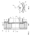
- in einem Querschnitt eine Nockenwellenverstelleinheit mit einem Rotor und einem Stator, wobei dem Rotor eine Klemmscheibe gemäß
Fig. 2 aufgelegt ist, und - Fig. 3
- eine Detailansicht der Ausbuchtung der Klemmscheibe.
-
Fig. 1 zeigt eine Klemmscheibe 1 zu einer form- und/oder kraftschlüssigen Kopplung einer Nockenwellenverstelleinheit mit einer Nockenwelle einer Brennkraftmaschine. Die Klemmscheibe 1 umfasst einen im Wesentlichen kreisringförmigen Grundkörper 2, auf dem eine reibungserhöhende Hartschicht 4 aufgebracht ist. Der Außenumfang des Grundkörpers 2 weicht von einer Kreisform geringfügig ab. In einem Winkelabstand von jeweils 120° sind insgesamt drei Ausbuchtungen 6 vorgesehen. Der größte umschriebene Durchmesser 7 des Grundkörpers 2 resultiert aus der radialen Ausdehnung der Ausbuchtungen 6. - Am Innenumfang 9 des Grundkörpers 2 ist der Grundkörper 2 durch eine Materialaussparung 10 etwa an der Acht-Uhr-Position axial durchbrochen. Durch diese Materialaussparung 10 hindurch ist aus axialer Richtung eine Abstandsmessung bezüglich der Auflagefläche der Klemmscheibe 10 ermöglicht. Am Außenumfang 5 umfasst der Grundkörper 2 weiter eine sich radial nach außen erstreckende Positioniernase 12. Die Positioniernase 12 ist an der Sechs-Uhr-Position angeordnet. Positioniernase 12 und Materialaussparung 10 sind in einer definierten Winkellage zueinander angeordnet.
- Gegenüber der Positioniernase 12 weist der Innenumfang 9 des Grundkörpers 2 eine Abflachung 14 auf. Über diese Abflachung 14 ist eine relativ einfache Demontage der Klemmscheibe 1 von der Unterlage möglich. Mittels eines geeigneten Werkzeugs wird die Klemmscheibe 1 an der Abflachung 14 ausgehebelt, so dass ein Abziehen der Positioniernase 12 aus der komplementären Vertiefung möglich wird.
- Aus dem in
Fig. 2 gezeigten Querschnitt einer Nockenwellenverstelleinheit 15 wird die Lage der montierten Klemmscheibe 1 gemäßFig. 1 ersichtlich. Die Nockenwellenverstelleinheit 15 umfasst einen Stator 17, in dem ein Rotor 19 drehbar gelagert ist. Der Stator 17 weist einen Seitendeckel 20 sowie einen Dichtdeckel 21 auf. Stator 17 und Rotor 19 rotieren gemeinsam gegenüber einer Zentralachse 22. - Der Seitendeckel 20 umfasst eine Bohrung 23, über die eine nicht dargestellte Nockenwelle aufgenommen werden kann. Zur Montage der Nockenwellenverstelleinheit 15 ist in den Dichtdeckel 21 eine weitere Bohrung 24 eingebracht. Über diese Bohrung 24 wird eine Zentralschraube eingeführt, die in eine Gewindebohrung auf der Stirnfläche der Nockenwelle eindrehbar ist. Durch Eindrehen der Zentralschraube wird die Nockenwellenverstelleinheit 15 insgesamt gegen die Stirnfläche der Nockenwelle verschraubt.
- Auf der der Nockenwelle zugewandten Seite des Rotors 19 ist eine Klemmscheibe 1 ähnlich
Fig. 1 aufgebracht. Beim Einschrauben der Zentralschraube wird eine Normalkraft auf die Kontaktflächen zwischen Rotor und Klemmscheibe einerseits und zwischen Klemmscheibe und Stirnfläche der Nockenwelle andererseits erzeugt. Über diese Normalkraft erfolgt eine kraft- oder reibschlüssige Verbindung des Rotors 19 mit der Stirnfläche der Nockenwelle, wobei die Klemmscheibe 1 reibungserhöhend zwischen Rotor 19 und Nockenwelle eingefügt ist. - Es wird erkennbar, dass der in
Fig. 2 sichtbare Außendurchmesser der Klemmscheibe 1 größer als der Innendurchmesser der Bohrung 23 des Seitendeckels 20 ist. Zur Montage wird die Klemmscheibe 1 über die Bohrung 23 unter Verbiegung eingeführt. Hinter dem Hinterschnitt 28 des Seitendeckels 20 verrastet somit die Klemmscheibe 1 verliersicher. - Der Innenumfang 9 des Grundkörpers 2 der Klemmscheibe 1 erstreckt sich radial über den Innenumfang des Rotors 19 hinaus. Eine nockenwellenseitige Abstandsmessung zur Oberfläche des Rotors 19 ist somit grundsätzlich nicht möglich. Aus diesem Grund weist der Grundkörper 2 der Klemmscheibe 1 eine Einbuchtung 10 an seinem Innenumfang 9 auf, so dass hierdurch für einen Messtaster 30 Zugang zur Oberfläche des Rotors 19 geschaffen ist.
- Zu einer winkelgetreuen Positionierung der Klemmscheibe 1 gegenüber der Nockenwellenverstelleinheit 15 umfasst der Grundkörper entsprechend
Fig. 1 eine Positioniernase 12. Diese Positioniernase 12 ist in eine entsprechende Vertiefung an axial überstehenden Abschnitten 27 des Rotors 19 eingesetzt. - In
Fig. 3 ist in einem Querschnitt senkrecht zur Zentralachse 22 eine Detailansicht der Materialaussparung 10 des Grundkörpers 2 gezeigt. Man erkennt, dass der Messtaster 30 die Materialaussparung 10 durchsetzt, um einen Abstand zur Oberfläche des Rotors 19 erfassen zu können. EntsprechendFig. 3 ist eine Positioniernase 12 des Grundkörpers 2 an gleicher Winkellage wie die Materialaussparung 10 angeordnet. Es wird deutlich, dass bei einer solchen Ausführungsvariante keine Materialschwächung im Grundkörper 2 auftritt. - Die sich radial nach außen erstreckende Positioniernase 12 des Grundkörpers 2 taucht im montierten Zustand in eine Vertiefung 31 des axial überstehenden Abschnitts 27 des Rotors 19 ein.
-
- 1
- Klemmscheibe
- 2
- Grundkörper
- 4
- Hartfläche
- 5
- Außenumfang
- 6
- Ausbuchtungen
- 7
- Größter umschriebener Durchmesser
- 9
- Innenumfang
- 10
- Materialaussparung
- 12
- Positioniernase
- 14
- Abflachung
- 15
- Nockenwellenverstelleinheit
- 17
- Stator
- 19
- Rotor
- 20
- Seitendeckel
- 21
- Dichtdeckel
- 22
- Zentralachse
- 23
- Bohrung
- 24
- Bohrung
- 27
- Abschnitt
- 28
- Hinterschnitt
- 30
- Messtaster
- 31
- Vertiefung
Claims (11)
- Nockenwellenverstelleinheit (15) für eine Brennkraftmaschine, mit einem innerhalb eines Stators (17) drehbar gelagerten Rotor (19) und einer Klemmscheibe (1), welche auf der der Nockenwelle zugewandten Seite des Rotors (19) zur form- und/oder kraftschlüssigen Kopplung der Nockenwellenverstelleinheit (15) mit der Nockenwelle positioniert ist, wobei die Klemmscheibe (1) einen im Wesentlichen kreisringförmigen Grundkörper (2) aufweist, der Kontaktflächen zum Rotor (19) der Nockenwellenverstelleinheit (15) und zur Stirnfläche der Nockenwelle hat, wobei auf diese Kontaktflächen eine Normalkraft erzeugt werden kann, wobei durch diese Normalkraft eine kraftschlüssige Verbindung zwischen dem Rotor (19) und der Stirnfläche der Nockenwelle erfolgen kann, wobei die Klemmscheibe (1) mit einer Schicht mit Mikro- oder Makrorauigkeiten zur Herstellung eines Formschlusses mit dem Kontaktpartner versehen ist, dadurch gekennzeichnet, dass der Grundkörper (2) durch eine Materialaussparung (10) axial durchbrochen ist und der Grundkörper (2) weiter ein Positionierungsmittel (12) umfasst, welches in einer vorgegebenen Winkellage zur Materialaussparung (10) angeordnet ist, wobei das Positionierungsmittel (12) eine definierte Winkellage der Klemmscheibe (1) gegenüber der Nockenwellenverstelleinheit (15) realisiert.
- Nockenwellenverstelleinheit (15) nach Anspruch 1, dadurch gekennzeichnet, dass der Grundkörper (2) der Klemmscheibe (1) am Innenumfang (9) eine Abflachung (14) aufweist, welche zur Demontage der Klemmscheibe (1) vorgesehen ist.
- Nockenwellenverstelleinheit (15) nach einem der vorhergehenden Ansprüche, dadurch gekennzeichnet, dass die Materialaussparung (10) als eine Einbuchtung am Innenumfang (9) des Grundkörpers (2) der Klemmscheibe (1) ausgebildet ist.
- Nockenwellenverstelleinheit (15) nach einem der vorhergehenden Ansprüche, dadurch gekennzeichnet, dass das Positionierungsmittel als eine Positioniernase (12) ausgebildet ist.
- Nockenwellenverstelleinheit (15) nach Anspruch 4, dadurch gekennzeichnet, dass sich die Positioniernase (12) am Außenumfang (5) radial nach außen erstreckt.
- Nockenwellenverstelleinheit (15) nach Anspruch 3 und Anspruch 5, dadurch gekennzeichnet, dass die Einbuchtung und die sich radial nach außen erstreckende Positioniernase (12) an gleicher Winkelposition des Grundkörpers (2) angeordnet sind.
- Nockenwellenverstelleinheit (15) nach Anspruch 6 , dadurch gekennzeichnet, dass der Rotor (19) in axialer Richtung zumindest abschnittsweise die Klemmscheibe (1) übergreift, und dass die sich radial nach auβen erstreckende Positioniernase (12) der Klemmscheibe (1) in eine Vertiefung (31) des übergreifenden Abschnitts (27) des Rotors (19) eingesetzt ist.
- Nockenwellenverstelleinheit (15) nach Anspruch 7, dadurch gekennzeichnet, dass der Stator (17) nockenwellenseitig einen Seitendeckel (20) mit einer axialen Bohrung (23) zur Aufnahme der Nockenwelle umfasst, dass der Innendurchmesser der Bohrung (23) kleiner als der größte umschriebene Außendurchmesser (7) der Klemmscheibe (1) ist, und dass die Klemmscheibe (1) in einen Hinterschnitt (28) des Seitendeckels (20) verliersicher eingesetzt ist.
- Verfahren zur Überprüfung der Montage einer Klemmscheibe (1) in einer Nockenwellenverstelleinheit (15) nach einem der Ansprüche 1 bis 8, gekennzeichnet durch die Schritte- Winkelausrichten der Nockenwellenverstelleinheit (15),- nockenwellenseitiges Aufbringen der Klemmscheibe (1) auf den Rotor (19),- nockenwellenseitiges Messen einer Abstandsdifferenz zwischen der Oberfläche der Klemmscheibe (1) und der durch die Materialaussparung (10) hindurch erfassten Oberfläche des Rotors (19),- Vergleichen der gemessenen Abstandsdifferenz mit einer Solldicke der Klemmscheibe (1) und- Aussortieren der Nockenwellenverstelleinheit (15) bei Feststellen einer Abweichung der Abstandsdifferenz von der Solldicke außerhalb eines Toleranzwertes.
- Verfahren nach Anspruch 9, dadurch gekennzeichnet, dass die Klemmscheibe (1) anhand des Positionierungsmittels (12) mit definierter Winkellage dem Rotor (19) aufgelegt wird.
- Verfahren nach Anspruch 9 oder 10, dadurch gekennzeichnet, dass die Abstandsdifferenz mittels eines in der Winkellage ausgerichteten Messtasters (30) durch die Bohrung (23) des Seitendeckels (20) hindurch gemessen wird.
Applications Claiming Priority (2)
| Application Number | Priority Date | Filing Date | Title |
|---|---|---|---|
| DE102010007488 | 2010-02-09 | ||
| PCT/EP2011/051796 WO2011098441A1 (de) | 2010-02-09 | 2011-02-08 | Klemmscheibe sowie nockenverstelleinheit |
Publications (2)
| Publication Number | Publication Date |
|---|---|
| EP2534384A1 EP2534384A1 (de) | 2012-12-19 |
| EP2534384B1 true EP2534384B1 (de) | 2014-04-09 |
Family
ID=44201916
Family Applications (1)
| Application Number | Title | Priority Date | Filing Date |
|---|---|---|---|
| EP11703209.4A Active EP2534384B1 (de) | 2010-02-09 | 2011-02-08 | Klemmscheibe sowie nockenverstelleinheit |
Country Status (6)
| Country | Link |
|---|---|
| US (1) | US8844483B2 (de) |
| EP (1) | EP2534384B1 (de) |
| CN (1) | CN102753842B (de) |
| BR (1) | BR112012019545A2 (de) |
| DE (1) | DE102011003766A1 (de) |
| WO (1) | WO2011098441A1 (de) |
Families Citing this family (4)
| Publication number | Priority date | Publication date | Assignee | Title |
|---|---|---|---|---|
| JP6502170B2 (ja) * | 2015-05-14 | 2019-04-17 | 愛知機械工業株式会社 | 隙間調整部材および隙間調整部材の組付け方法並びに変速装置 |
| DE102016103703A1 (de) * | 2016-03-02 | 2017-09-07 | Norma Germany Gmbh | Profilschelle |
| DE102019212208B4 (de) * | 2019-08-14 | 2021-05-27 | Zf Friedrichshafen Ag | Wellengenerator und Spannungswellengetriebe |
| CN116922302B (zh) * | 2023-08-14 | 2026-04-14 | 联合汽车电子有限公司 | 一种轴承的固定结构 |
Family Cites Families (20)
| Publication number | Priority date | Publication date | Assignee | Title |
|---|---|---|---|---|
| GB359836A (en) * | 1931-02-10 | 1931-10-29 | Herbert Wills | Improvements in or relating to gudgeon pin securing devices |
| GB484105A (en) | 1936-10-30 | 1938-05-02 | Specialloid Ltd | Improvements in and relating to spring rings or circlips |
| US3102508A (en) | 1961-10-19 | 1963-09-03 | Jr Sidney R Smith | Light condition indicating device |
| DE2105990A1 (de) * | 1971-02-09 | 1972-08-17 | Sieler H | Befestigungsring |
| GB1416067A (en) * | 1973-07-23 | 1975-12-03 | United Carr Ltd | Washers |
| JPS5477849A (en) | 1977-12-01 | 1979-06-21 | Taiyou Hatsujiyou Seisakushiyo | C type retaining ring |
| US4343581A (en) | 1979-05-21 | 1982-08-10 | Waldes Kohinoor, Inc. | Double-bevel spring retaining ring |
| US5195860A (en) * | 1992-07-20 | 1993-03-23 | Trw Inc. | Push-on type fastener for automatic feed and installation equipment |
| US5383938A (en) * | 1993-02-12 | 1995-01-24 | Zimmer, Inc. | Locking ring for an acetabular cup |
| DE4444922C1 (de) * | 1994-12-16 | 1996-03-07 | Ford Werke Ag | Befestigungsanordnung für einen Sensor |
| US5713692A (en) | 1996-07-17 | 1998-02-03 | Span Instruments | Inventory control collar locking ring |
| DE19850048A1 (de) | 1998-10-30 | 2000-05-04 | Christian Majaura | Verschleißfeste Hartstoffschichten auf Metallkörpern |
| EP1050665B1 (de) * | 1999-05-03 | 2005-12-07 | General Electric Company | Klemmring zur Fixierung von Kühlrohren in einem Gasturbinenrotor |
| DE19936708A1 (de) * | 1999-08-06 | 2001-02-08 | Bosch Gmbh Robert | Sicherungsring |
| US6814208B2 (en) * | 2001-06-07 | 2004-11-09 | Drussel Wilfley Design, L.L.C. | Multi-row cam-actuated centrifugal clutch |
| DE10161698A1 (de) * | 2001-12-15 | 2003-06-26 | Ina Schaeffler Kg | Vorrichtung zum Verändern der Steuerzeiten von Gaswechselventilen einer Brennkraftmaschine, insbesondere Einrichtung zur hydraulischen Drehwinkelverstellung einer Nockenwelle gegenüber einer Kurbelwelle |
| DE102005007384A1 (de) * | 2005-02-18 | 2006-08-31 | Zf Friedrichshafen Ag | Anordnung zur axialen Abstützung von zwei miteinander rotierenden Bauteilen |
| DE102005042346A1 (de) * | 2005-09-07 | 2007-03-08 | Zf Friedrichshafen Ag | Ringförmiges, axiales Sicherungselement, insbesondere Sicherungsring |
| DE102006036034B4 (de) | 2006-08-02 | 2018-01-04 | Schaeffler Technologies AG & Co. KG | Antriebseinrichtung zwischen einem Nockenwellenversteller und einer Nockenwelle |
| DE102008013966A1 (de) | 2008-03-12 | 2009-09-17 | Kennametal Inc. | Hartstoffbeschichteter Körper |
-
2011
- 2011-02-08 BR BR112012019545-0A patent/BR112012019545A2/pt not_active IP Right Cessation
- 2011-02-08 WO PCT/EP2011/051796 patent/WO2011098441A1/de not_active Ceased
- 2011-02-08 CN CN201180008855.3A patent/CN102753842B/zh active Active
- 2011-02-08 US US13/577,333 patent/US8844483B2/en active Active
- 2011-02-08 DE DE102011003766A patent/DE102011003766A1/de not_active Withdrawn
- 2011-02-08 EP EP11703209.4A patent/EP2534384B1/de active Active
Also Published As
| Publication number | Publication date |
|---|---|
| CN102753842A (zh) | 2012-10-24 |
| US20120304946A1 (en) | 2012-12-06 |
| CN102753842B (zh) | 2015-02-04 |
| BR112012019545A2 (pt) | 2018-03-27 |
| US8844483B2 (en) | 2014-09-30 |
| EP2534384A1 (de) | 2012-12-19 |
| WO2011098441A1 (de) | 2011-08-18 |
| DE102011003766A1 (de) | 2011-08-11 |
Similar Documents
| Publication | Publication Date | Title |
|---|---|---|
| EP2619421B1 (de) | Rotor für einen nockenwellenversteller und nockenwellenverstellsystem | |
| DE10145947C1 (de) | Bremse | |
| DE102009050779B4 (de) | Schwenkmotornockenwellenversteller mit einer Reibscheibe und Montageverfahren | |
| EP3662240B1 (de) | Maschinenelement mit einer sensoreinrichtung und verfahren zur herstellung eines maschinenelements | |
| DE102011119251B4 (de) | Vorrichtung zur Krafteinleitung in ein Bauteil aus Faserverbundwerkstoff | |
| EP1511922B1 (de) | Getriebe einer nockenwelle mit zwei ineinander angeordneten drehscheiben, die durch eine taumelscheibe miteinander verbunden sind | |
| DE10161698A1 (de) | Vorrichtung zum Verändern der Steuerzeiten von Gaswechselventilen einer Brennkraftmaschine, insbesondere Einrichtung zur hydraulischen Drehwinkelverstellung einer Nockenwelle gegenüber einer Kurbelwelle | |
| DE10161701A1 (de) | Vorrichtung zum Verändern der Steuerzeiten von Gaswechselventilen einer Brennkraftmaschine, insbesondere Einrichtung zur hydraulischen Drehwinkelverstellung einer Nockenwelle gegenüber einer Kurbelwelle | |
| WO2012104242A1 (de) | Vorrichtung zur veränderung der relativen winkellage einer nockenwelle gegenüber einer kurbelwelle einer brennkraftmaschine | |
| DE102012024264A1 (de) | Drehmomentsensor | |
| WO2011098441A1 (de) | Klemmscheibe sowie nockenverstelleinheit | |
| EP2954291A1 (de) | Sensoranordnung zur erfassung der winkelstellung einer welle und verfahren zum verbinden einer sensoranordnung | |
| WO2013174543A1 (de) | Nockenwellenverstelleinrichtung | |
| DE102014218234B4 (de) | Oldhamkupplung und Verfahren zur Herstellung einer Oldhamkupplung | |
| DE102005031832A1 (de) | Vorgespannte Welle-Nabe-Verbindung mit Realkegel | |
| DE102006036034A1 (de) | Antriebseinrichtung zwischen einem Nockenwellenversteller und einer Nockenwelle | |
| DE20211065U1 (de) | Hydrodynamisches Drucklager | |
| WO2011157541A1 (de) | Reibscheibe und nockenwellenverstellsystem | |
| EP2631607A1 (de) | Adapter zur Montage zweier Encoder an einer Welle | |
| EP1467111A2 (de) | Verfahren zur Einstellung des Spiels oder der Vorspannung eines Lagers | |
| EP3517743B1 (de) | Schwenkmotorversteller für eine nockenwelle und nockenwellenanordnung mit einer nockenwelle und einem schwenkmotorversteller | |
| EP2290251A1 (de) | Verfahren und Vorrichtung zum axialen Sichern eines Maschinenelements | |
| DE10109660A1 (de) | Sicherungsring und Befestigungsvorrichtung für eine Welle-Nabe-Verbindung | |
| DE102015217559A1 (de) | Stellgetriebe | |
| DE102018126302A1 (de) | Schwenkmotorversteller für eine Nockenwelle und Nockenwellenanordnung mit einer Nockenwelle und einem Schwenkmotorversteller |
Legal Events
| Date | Code | Title | Description |
|---|---|---|---|
| PUAI | Public reference made under article 153(3) epc to a published international application that has entered the european phase |
Free format text: ORIGINAL CODE: 0009012 |
|
| 17P | Request for examination filed |
Effective date: 20120910 |
|
| AK | Designated contracting states |
Kind code of ref document: A1 Designated state(s): AL AT BE BG CH CY CZ DE DK EE ES FI FR GB GR HR HU IE IS IT LI LT LU LV MC MK MT NL NO PL PT RO RS SE SI SK SM TR |
|
| DAX | Request for extension of the european patent (deleted) | ||
| GRAP | Despatch of communication of intention to grant a patent |
Free format text: ORIGINAL CODE: EPIDOSNIGR1 |
|
| INTG | Intention to grant announced |
Effective date: 20131028 |
|
| GRAS | Grant fee paid |
Free format text: ORIGINAL CODE: EPIDOSNIGR3 |
|
| GRAA | (expected) grant |
Free format text: ORIGINAL CODE: 0009210 |
|
| RAP1 | Party data changed (applicant data changed or rights of an application transferred) |
Owner name: SCHAEFFLER TECHNOLOGIES GMBH & CO. KG |
|
| AK | Designated contracting states |
Kind code of ref document: B1 Designated state(s): AL AT BE BG CH CY CZ DE DK EE ES FI FR GB GR HR HU IE IS IT LI LT LU LV MC MK MT NL NO PL PT RO RS SE SI SK SM TR |
|
| REG | Reference to a national code |
Ref country code: GB Ref legal event code: FG4D Free format text: NOT ENGLISH |
|
| REG | Reference to a national code |
Ref country code: AT Ref legal event code: REF Ref document number: 661502 Country of ref document: AT Kind code of ref document: T Effective date: 20140415 Ref country code: CH Ref legal event code: EP |
|
| REG | Reference to a national code |
Ref country code: IE Ref legal event code: FG4D Free format text: LANGUAGE OF EP DOCUMENT: GERMAN |
|
| REG | Reference to a national code |
Ref country code: DE Ref legal event code: R096 Ref document number: 502011002667 Country of ref document: DE Effective date: 20140522 |
|
| REG | Reference to a national code |
Ref country code: NL Ref legal event code: VDEP Effective date: 20140409 |
|
| REG | Reference to a national code |
Ref country code: LT Ref legal event code: MG4D |
|
| PG25 | Lapsed in a contracting state [announced via postgrant information from national office to epo] |
Ref country code: FI Free format text: LAPSE BECAUSE OF FAILURE TO SUBMIT A TRANSLATION OF THE DESCRIPTION OR TO PAY THE FEE WITHIN THE PRESCRIBED TIME-LIMIT Effective date: 20140409 Ref country code: LT Free format text: LAPSE BECAUSE OF FAILURE TO SUBMIT A TRANSLATION OF THE DESCRIPTION OR TO PAY THE FEE WITHIN THE PRESCRIBED TIME-LIMIT Effective date: 20140409 Ref country code: BG Free format text: LAPSE BECAUSE OF FAILURE TO SUBMIT A TRANSLATION OF THE DESCRIPTION OR TO PAY THE FEE WITHIN THE PRESCRIBED TIME-LIMIT Effective date: 20140709 Ref country code: GR Free format text: LAPSE BECAUSE OF FAILURE TO SUBMIT A TRANSLATION OF THE DESCRIPTION OR TO PAY THE FEE WITHIN THE PRESCRIBED TIME-LIMIT Effective date: 20140710 Ref country code: IS Free format text: LAPSE BECAUSE OF FAILURE TO SUBMIT A TRANSLATION OF THE DESCRIPTION OR TO PAY THE FEE WITHIN THE PRESCRIBED TIME-LIMIT Effective date: 20140809 Ref country code: NO Free format text: LAPSE BECAUSE OF FAILURE TO SUBMIT A TRANSLATION OF THE DESCRIPTION OR TO PAY THE FEE WITHIN THE PRESCRIBED TIME-LIMIT Effective date: 20140709 Ref country code: NL Free format text: LAPSE BECAUSE OF FAILURE TO SUBMIT A TRANSLATION OF THE DESCRIPTION OR TO PAY THE FEE WITHIN THE PRESCRIBED TIME-LIMIT Effective date: 20140409 |
|
| PG25 | Lapsed in a contracting state [announced via postgrant information from national office to epo] |
Ref country code: LV Free format text: LAPSE BECAUSE OF FAILURE TO SUBMIT A TRANSLATION OF THE DESCRIPTION OR TO PAY THE FEE WITHIN THE PRESCRIBED TIME-LIMIT Effective date: 20140409 Ref country code: SE Free format text: LAPSE BECAUSE OF FAILURE TO SUBMIT A TRANSLATION OF THE DESCRIPTION OR TO PAY THE FEE WITHIN THE PRESCRIBED TIME-LIMIT Effective date: 20140409 Ref country code: PL Free format text: LAPSE BECAUSE OF FAILURE TO SUBMIT A TRANSLATION OF THE DESCRIPTION OR TO PAY THE FEE WITHIN THE PRESCRIBED TIME-LIMIT Effective date: 20140409 Ref country code: HR Free format text: LAPSE BECAUSE OF FAILURE TO SUBMIT A TRANSLATION OF THE DESCRIPTION OR TO PAY THE FEE WITHIN THE PRESCRIBED TIME-LIMIT Effective date: 20140409 Ref country code: ES Free format text: LAPSE BECAUSE OF FAILURE TO SUBMIT A TRANSLATION OF THE DESCRIPTION OR TO PAY THE FEE WITHIN THE PRESCRIBED TIME-LIMIT Effective date: 20140409 Ref country code: RS Free format text: LAPSE BECAUSE OF FAILURE TO SUBMIT A TRANSLATION OF THE DESCRIPTION OR TO PAY THE FEE WITHIN THE PRESCRIBED TIME-LIMIT Effective date: 20140409 |
|
| REG | Reference to a national code |
Ref country code: HU Ref legal event code: AG4A Ref document number: E021221 Country of ref document: HU |
|
| PG25 | Lapsed in a contracting state [announced via postgrant information from national office to epo] |
Ref country code: PT Free format text: LAPSE BECAUSE OF FAILURE TO SUBMIT A TRANSLATION OF THE DESCRIPTION OR TO PAY THE FEE WITHIN THE PRESCRIBED TIME-LIMIT Effective date: 20140811 |
|
| REG | Reference to a national code |
Ref country code: DE Ref legal event code: R097 Ref document number: 502011002667 Country of ref document: DE |
|
| PG25 | Lapsed in a contracting state [announced via postgrant information from national office to epo] |
Ref country code: EE Free format text: LAPSE BECAUSE OF FAILURE TO SUBMIT A TRANSLATION OF THE DESCRIPTION OR TO PAY THE FEE WITHIN THE PRESCRIBED TIME-LIMIT Effective date: 20140409 Ref country code: DK Free format text: LAPSE BECAUSE OF FAILURE TO SUBMIT A TRANSLATION OF THE DESCRIPTION OR TO PAY THE FEE WITHIN THE PRESCRIBED TIME-LIMIT Effective date: 20140409 Ref country code: SK Free format text: LAPSE BECAUSE OF FAILURE TO SUBMIT A TRANSLATION OF THE DESCRIPTION OR TO PAY THE FEE WITHIN THE PRESCRIBED TIME-LIMIT Effective date: 20140409 Ref country code: CZ Free format text: LAPSE BECAUSE OF FAILURE TO SUBMIT A TRANSLATION OF THE DESCRIPTION OR TO PAY THE FEE WITHIN THE PRESCRIBED TIME-LIMIT Effective date: 20140409 Ref country code: RO Free format text: LAPSE BECAUSE OF FAILURE TO SUBMIT A TRANSLATION OF THE DESCRIPTION OR TO PAY THE FEE WITHIN THE PRESCRIBED TIME-LIMIT Effective date: 20140409 |
|
| PLBE | No opposition filed within time limit |
Free format text: ORIGINAL CODE: 0009261 |
|
| STAA | Information on the status of an ep patent application or granted ep patent |
Free format text: STATUS: NO OPPOSITION FILED WITHIN TIME LIMIT |
|
| RAP2 | Party data changed (patent owner data changed or rights of a patent transferred) |
Owner name: SCHAEFFLER TECHNOLOGIES AG & CO. KG |
|
| REG | Reference to a national code |
Ref country code: DE Ref legal event code: R081 Ref document number: 502011002667 Country of ref document: DE Owner name: SCHAEFFLER TECHNOLOGIES AG & CO. KG, DE Free format text: FORMER OWNER: SCHAEFFLER TECHNOLOGIES GMBH & CO. KG, 91074 HERZOGENAURACH, DE Effective date: 20150122 |
|
| 26N | No opposition filed |
Effective date: 20150112 |
|
| PG25 | Lapsed in a contracting state [announced via postgrant information from national office to epo] |
Ref country code: IT Free format text: LAPSE BECAUSE OF FAILURE TO SUBMIT A TRANSLATION OF THE DESCRIPTION OR TO PAY THE FEE WITHIN THE PRESCRIBED TIME-LIMIT Effective date: 20140409 |
|
| REG | Reference to a national code |
Ref country code: DE Ref legal event code: R097 Ref document number: 502011002667 Country of ref document: DE Effective date: 20150112 |
|
| PG25 | Lapsed in a contracting state [announced via postgrant information from national office to epo] |
Ref country code: BE Free format text: LAPSE BECAUSE OF NON-PAYMENT OF DUE FEES Effective date: 20150228 |
|
| PG25 | Lapsed in a contracting state [announced via postgrant information from national office to epo] |
Ref country code: SI Free format text: LAPSE BECAUSE OF FAILURE TO SUBMIT A TRANSLATION OF THE DESCRIPTION OR TO PAY THE FEE WITHIN THE PRESCRIBED TIME-LIMIT Effective date: 20140409 |
|
| REG | Reference to a national code |
Ref country code: HU Ref legal event code: FH1C Free format text: FORMER REPRESENTATIVE(S): DR. JAKABNE MOLNAR JUDIT, SBGK SZABADALMI UEGYVIVOEI IRODA, HU Representative=s name: SBGK SZABADALMI UEGYVIVOEI IRODA, HU Ref country code: HU Ref legal event code: GB9C Owner name: SCHAEFFLER TECHNOLOGIES AG & CO. KG, DE Free format text: FORMER OWNER(S): SCHAEFFLER TECHNOLOGIES GMBH & CO. KG, DE |
|
| PG25 | Lapsed in a contracting state [announced via postgrant information from national office to epo] |
Ref country code: LU Free format text: LAPSE BECAUSE OF FAILURE TO SUBMIT A TRANSLATION OF THE DESCRIPTION OR TO PAY THE FEE WITHIN THE PRESCRIBED TIME-LIMIT Effective date: 20150208 |
|
| REG | Reference to a national code |
Ref country code: CH Ref legal event code: PL |
|
| GBPC | Gb: european patent ceased through non-payment of renewal fee |
Effective date: 20150208 |
|
| PG25 | Lapsed in a contracting state [announced via postgrant information from national office to epo] |
Ref country code: MC Free format text: LAPSE BECAUSE OF FAILURE TO SUBMIT A TRANSLATION OF THE DESCRIPTION OR TO PAY THE FEE WITHIN THE PRESCRIBED TIME-LIMIT Effective date: 20140409 Ref country code: LI Free format text: LAPSE BECAUSE OF NON-PAYMENT OF DUE FEES Effective date: 20150228 Ref country code: CH Free format text: LAPSE BECAUSE OF NON-PAYMENT OF DUE FEES Effective date: 20150228 |
|
| REG | Reference to a national code |
Ref country code: IE Ref legal event code: MM4A |
|
| PG25 | Lapsed in a contracting state [announced via postgrant information from national office to epo] |
Ref country code: GB Free format text: LAPSE BECAUSE OF NON-PAYMENT OF DUE FEES Effective date: 20150208 Ref country code: IE Free format text: LAPSE BECAUSE OF NON-PAYMENT OF DUE FEES Effective date: 20150208 |
|
| REG | Reference to a national code |
Ref country code: FR Ref legal event code: PLFP Year of fee payment: 6 |
|
| PG25 | Lapsed in a contracting state [announced via postgrant information from national office to epo] |
Ref country code: MT Free format text: LAPSE BECAUSE OF FAILURE TO SUBMIT A TRANSLATION OF THE DESCRIPTION OR TO PAY THE FEE WITHIN THE PRESCRIBED TIME-LIMIT Effective date: 20140409 |
|
| REG | Reference to a national code |
Ref country code: FR Ref legal event code: PLFP Year of fee payment: 7 |
|
| REG | Reference to a national code |
Ref country code: AT Ref legal event code: MM01 Ref document number: 661502 Country of ref document: AT Kind code of ref document: T Effective date: 20160208 |
|
| PGFP | Annual fee paid to national office [announced via postgrant information from national office to epo] |
Ref country code: FR Payment date: 20170224 Year of fee payment: 7 |
|
| PG25 | Lapsed in a contracting state [announced via postgrant information from national office to epo] |
Ref country code: AT Free format text: LAPSE BECAUSE OF NON-PAYMENT OF DUE FEES Effective date: 20160208 Ref country code: SM Free format text: LAPSE BECAUSE OF FAILURE TO SUBMIT A TRANSLATION OF THE DESCRIPTION OR TO PAY THE FEE WITHIN THE PRESCRIBED TIME-LIMIT Effective date: 20140409 |
|
| PG25 | Lapsed in a contracting state [announced via postgrant information from national office to epo] |
Ref country code: CY Free format text: LAPSE BECAUSE OF FAILURE TO SUBMIT A TRANSLATION OF THE DESCRIPTION OR TO PAY THE FEE WITHIN THE PRESCRIBED TIME-LIMIT Effective date: 20140409 |
|
| PG25 | Lapsed in a contracting state [announced via postgrant information from national office to epo] |
Ref country code: TR Free format text: LAPSE BECAUSE OF FAILURE TO SUBMIT A TRANSLATION OF THE DESCRIPTION OR TO PAY THE FEE WITHIN THE PRESCRIBED TIME-LIMIT Effective date: 20140409 |
|
| PG25 | Lapsed in a contracting state [announced via postgrant information from national office to epo] |
Ref country code: MK Free format text: LAPSE BECAUSE OF FAILURE TO SUBMIT A TRANSLATION OF THE DESCRIPTION OR TO PAY THE FEE WITHIN THE PRESCRIBED TIME-LIMIT Effective date: 20140409 |
|
| PG25 | Lapsed in a contracting state [announced via postgrant information from national office to epo] |
Ref country code: AL Free format text: LAPSE BECAUSE OF FAILURE TO SUBMIT A TRANSLATION OF THE DESCRIPTION OR TO PAY THE FEE WITHIN THE PRESCRIBED TIME-LIMIT Effective date: 20140409 |
|
| REG | Reference to a national code |
Ref country code: FR Ref legal event code: ST Effective date: 20181031 |
|
| PG25 | Lapsed in a contracting state [announced via postgrant information from national office to epo] |
Ref country code: FR Free format text: LAPSE BECAUSE OF NON-PAYMENT OF DUE FEES Effective date: 20180228 |
|
| P01 | Opt-out of the competence of the unified patent court (upc) registered |
Effective date: 20230522 |
|
| PGFP | Annual fee paid to national office [announced via postgrant information from national office to epo] |
Ref country code: HU Payment date: 20260220 Year of fee payment: 16 |
|
| PGFP | Annual fee paid to national office [announced via postgrant information from national office to epo] |
Ref country code: DE Payment date: 20260228 Year of fee payment: 16 |