EP2533829B1 - Implantable fluid router - Google Patents
Implantable fluid router Download PDFInfo
- Publication number
- EP2533829B1 EP2533829B1 EP11706899.9A EP11706899A EP2533829B1 EP 2533829 B1 EP2533829 B1 EP 2533829B1 EP 11706899 A EP11706899 A EP 11706899A EP 2533829 B1 EP2533829 B1 EP 2533829B1
- Authority
- EP
- European Patent Office
- Prior art keywords
- gas
- implantable
- fluid
- router
- implantable fluid
- Prior art date
- Legal status (The legal status is an assumption and is not a legal conclusion. Google has not performed a legal analysis and makes no representation as to the accuracy of the status listed.)
- Active
Links
Images


Classifications
-
- A—HUMAN NECESSITIES
- A61—MEDICAL OR VETERINARY SCIENCE; HYGIENE
- A61B—DIAGNOSIS; SURGERY; IDENTIFICATION
- A61B17/00—Surgical instruments, devices or methods
- A61B17/16—Instruments for performing osteoclasis; Drills or chisels for bones; Trepans
- A61B17/17—Guides or aligning means for drills, mills, pins or wires
- A61B17/1739—Guides or aligning means for drills, mills, pins or wires specially adapted for particular parts of the body
-
- A—HUMAN NECESSITIES
- A61—MEDICAL OR VETERINARY SCIENCE; HYGIENE
- A61M—DEVICES FOR INTRODUCING MEDIA INTO, OR ONTO, THE BODY; DEVICES FOR TRANSDUCING BODY MEDIA OR FOR TAKING MEDIA FROM THE BODY; DEVICES FOR PRODUCING OR ENDING SLEEP OR STUPOR
- A61M39/00—Tubes, tube connectors, tube couplings, valves, access sites or the like, specially adapted for medical use
- A61M39/02—Access sites
- A61M39/0247—Transcutaneous or percutaneous access sites to the inside of the body
-
- A—HUMAN NECESSITIES
- A61—MEDICAL OR VETERINARY SCIENCE; HYGIENE
- A61M—DEVICES FOR INTRODUCING MEDIA INTO, OR ONTO, THE BODY; DEVICES FOR TRANSDUCING BODY MEDIA OR FOR TAKING MEDIA FROM THE BODY; DEVICES FOR PRODUCING OR ENDING SLEEP OR STUPOR
- A61M5/00—Devices for bringing media into the body in a subcutaneous, intra-vascular or intramuscular way; Accessories therefor, e.g. filling or cleaning devices, arm rests
- A61M5/14—Infusion devices, e.g. infusing by gravity; Blood infusion; Accessories therefor
- A61M5/142—Pressure infusion, e.g. using pumps
- A61M5/14244—Pressure infusion, e.g. using pumps adapted to be carried by the patient, e.g. portable on the body
- A61M5/14276—Pressure infusion, e.g. using pumps adapted to be carried by the patient, e.g. portable on the body specially adapted for implantation
-
- A—HUMAN NECESSITIES
- A61—MEDICAL OR VETERINARY SCIENCE; HYGIENE
- A61M—DEVICES FOR INTRODUCING MEDIA INTO, OR ONTO, THE BODY; DEVICES FOR TRANSDUCING BODY MEDIA OR FOR TAKING MEDIA FROM THE BODY; DEVICES FOR PRODUCING OR ENDING SLEEP OR STUPOR
- A61M5/00—Devices for bringing media into the body in a subcutaneous, intra-vascular or intramuscular way; Accessories therefor, e.g. filling or cleaning devices, arm rests
- A61M5/36—Devices for bringing media into the body in a subcutaneous, intra-vascular or intramuscular way; Accessories therefor, e.g. filling or cleaning devices, arm rests with means for eliminating or preventing injection or infusion of air into body
-
- A—HUMAN NECESSITIES
- A61—MEDICAL OR VETERINARY SCIENCE; HYGIENE
- A61M—DEVICES FOR INTRODUCING MEDIA INTO, OR ONTO, THE BODY; DEVICES FOR TRANSDUCING BODY MEDIA OR FOR TAKING MEDIA FROM THE BODY; DEVICES FOR PRODUCING OR ENDING SLEEP OR STUPOR
- A61M39/00—Tubes, tube connectors, tube couplings, valves, access sites or the like, specially adapted for medical use
- A61M39/02—Access sites
- A61M39/0247—Transcutaneous or percutaneous access sites to the inside of the body
- A61M2039/0261—Means for anchoring port to the body, or ports having a special shape or being made of a specific material to allow easy implantation/integration in the body
-
- A—HUMAN NECESSITIES
- A61—MEDICAL OR VETERINARY SCIENCE; HYGIENE
- A61M—DEVICES FOR INTRODUCING MEDIA INTO, OR ONTO, THE BODY; DEVICES FOR TRANSDUCING BODY MEDIA OR FOR TAKING MEDIA FROM THE BODY; DEVICES FOR PRODUCING OR ENDING SLEEP OR STUPOR
- A61M39/00—Tubes, tube connectors, tube couplings, valves, access sites or the like, specially adapted for medical use
- A61M39/02—Access sites
- A61M39/0247—Transcutaneous or percutaneous access sites to the inside of the body
- A61M2039/0276—Transcutaneous or percutaneous access sites to the inside of the body for introducing or removing fluids into or out of the body
-
- A—HUMAN NECESSITIES
- A61—MEDICAL OR VETERINARY SCIENCE; HYGIENE
- A61M—DEVICES FOR INTRODUCING MEDIA INTO, OR ONTO, THE BODY; DEVICES FOR TRANSDUCING BODY MEDIA OR FOR TAKING MEDIA FROM THE BODY; DEVICES FOR PRODUCING OR ENDING SLEEP OR STUPOR
- A61M39/00—Tubes, tube connectors, tube couplings, valves, access sites or the like, specially adapted for medical use
- A61M39/02—Access sites
- A61M39/0247—Transcutaneous or percutaneous access sites to the inside of the body
- A61M2039/0282—Transcutaneous or percutaneous access sites to the inside of the body with implanted tubes connected to the port
-
- A—HUMAN NECESSITIES
- A61—MEDICAL OR VETERINARY SCIENCE; HYGIENE
- A61M—DEVICES FOR INTRODUCING MEDIA INTO, OR ONTO, THE BODY; DEVICES FOR TRANSDUCING BODY MEDIA OR FOR TAKING MEDIA FROM THE BODY; DEVICES FOR PRODUCING OR ENDING SLEEP OR STUPOR
- A61M39/00—Tubes, tube connectors, tube couplings, valves, access sites or the like, specially adapted for medical use
- A61M39/10—Tube connectors or tube couplings
- A61M2039/1083—Tube connectors or tube couplings having a plurality of female connectors, e.g. Luer connectors
-
- A—HUMAN NECESSITIES
- A61—MEDICAL OR VETERINARY SCIENCE; HYGIENE
- A61M—DEVICES FOR INTRODUCING MEDIA INTO, OR ONTO, THE BODY; DEVICES FOR TRANSDUCING BODY MEDIA OR FOR TAKING MEDIA FROM THE BODY; DEVICES FOR PRODUCING OR ENDING SLEEP OR STUPOR
- A61M39/00—Tubes, tube connectors, tube couplings, valves, access sites or the like, specially adapted for medical use
- A61M39/10—Tube connectors or tube couplings
- A61M2039/1088—Tube connectors or tube couplings having a plurality of male connectors, e.g. Luer connectors
-
- A—HUMAN NECESSITIES
- A61—MEDICAL OR VETERINARY SCIENCE; HYGIENE
- A61M—DEVICES FOR INTRODUCING MEDIA INTO, OR ONTO, THE BODY; DEVICES FOR TRANSDUCING BODY MEDIA OR FOR TAKING MEDIA FROM THE BODY; DEVICES FOR PRODUCING OR ENDING SLEEP OR STUPOR
- A61M2205/00—General characteristics of the apparatus
- A61M2205/02—General characteristics of the apparatus characterised by a particular materials
-
- A—HUMAN NECESSITIES
- A61—MEDICAL OR VETERINARY SCIENCE; HYGIENE
- A61M—DEVICES FOR INTRODUCING MEDIA INTO, OR ONTO, THE BODY; DEVICES FOR TRANSDUCING BODY MEDIA OR FOR TAKING MEDIA FROM THE BODY; DEVICES FOR PRODUCING OR ENDING SLEEP OR STUPOR
- A61M2205/00—General characteristics of the apparatus
- A61M2205/75—General characteristics of the apparatus with filters
- A61M2205/7518—General characteristics of the apparatus with filters bacterial
-
- A—HUMAN NECESSITIES
- A61—MEDICAL OR VETERINARY SCIENCE; HYGIENE
- A61M—DEVICES FOR INTRODUCING MEDIA INTO, OR ONTO, THE BODY; DEVICES FOR TRANSDUCING BODY MEDIA OR FOR TAKING MEDIA FROM THE BODY; DEVICES FOR PRODUCING OR ENDING SLEEP OR STUPOR
- A61M2210/00—Anatomical parts of the body
- A61M2210/06—Head
- A61M2210/0687—Skull, cranium
-
- A—HUMAN NECESSITIES
- A61—MEDICAL OR VETERINARY SCIENCE; HYGIENE
- A61M—DEVICES FOR INTRODUCING MEDIA INTO, OR ONTO, THE BODY; DEVICES FOR TRANSDUCING BODY MEDIA OR FOR TAKING MEDIA FROM THE BODY; DEVICES FOR PRODUCING OR ENDING SLEEP OR STUPOR
- A61M39/00—Tubes, tube connectors, tube couplings, valves, access sites or the like, specially adapted for medical use
- A61M39/10—Tube connectors or tube couplings
- A61M39/105—Multi-channel connectors or couplings, e.g. for connecting multi-lumen tubes
-
- A—HUMAN NECESSITIES
- A61—MEDICAL OR VETERINARY SCIENCE; HYGIENE
- A61M—DEVICES FOR INTRODUCING MEDIA INTO, OR ONTO, THE BODY; DEVICES FOR TRANSDUCING BODY MEDIA OR FOR TAKING MEDIA FROM THE BODY; DEVICES FOR PRODUCING OR ENDING SLEEP OR STUPOR
- A61M39/00—Tubes, tube connectors, tube couplings, valves, access sites or the like, specially adapted for medical use
- A61M39/22—Valves or arrangement of valves
- A61M39/223—Multiway valves
Definitions
- the present invention relates to implantable drug delivery apparatus for neurosurgical applications and in particular to an implantable fluid router that comprises a gas vent.
- Implantable drug delivery systems are known for the treatment of neurological conditions where the blood brain barrier prevents many systemically administered drugs from reaching the desired target, or where the delivery of drugs or therapeutic agents to targets other than the desired target may produce unacceptable side affects.
- it is known to deliver drugs and other therapeutic agents directly into the brain parenchyma via one or more implanted catheters.
- this type of therapy include the infusion of gamma-amino-butyric acid agonists into an epileptic focus or pathway that will block its transmission, the delivery of cytotoxic agents directly into a brain tumour, and the infusion of neurotrophic agents for the protection and repair of failing or damaged nerve cells.
- neurotrophic agents can be used to treat a variety of neurodegenerative disorders including Parkinson's disease, Alzheimer's disease and Amyotrophic Lateral Sclerosis, and may also be useful in stimulating the repair of damaged neural tissue after injury from trauma, stroke or inflammation.
- a pump is typically located in the abdomen and tubing is tunnelled subcutaneously to implanted intraparenchymal catheters. It is known for the pumps used in such systems to include bacterial filters, for example see GB2389791 or WO2009/128959 .
- a reservoir comprising a gas permeable membrane is described in US2007/255262 .
- an implantable fluid router comprising one or more inlets, one or more outlets and at least one gas vent for removing gas from liquid routed from the one or more inlets to the one or more outlets characterised in that each gas vent includes a chamber that comprises a gas permeable membrane through which gas present in liquid routed through the chamber may pass and a hydrophilic material through which liquid passes when routed through that chamber.
- the at least one gas vent of the fluid router acts to remove bubbles of gas (typically air) from any liquid that is being routed from an inlet to an outlet. The removal of air from liquid in such a manner prevents air bubbles occluding catheters located downstream of the fluid router thereby improving treatment efficacy and reliability.
- the implantable fluid router comprises a plurality of inlets, a plurality ofoutlets and a plurality of separate liquid pathways between the plurality of inlets and the plurality of outlets.
- the router comprises a plurality of gas vents.
- each liquid pathway comprises a separate gas vent. In this manner separate fluid pathways through the router, with separate gas vents, are provided.
- Such a device may be used to separately connect the different lumen of a multi-lumen supply tube (or multiple single lumen supply tubes) to multiple catheters.
- the implantable fluid router may comprise one inlet, one outlet and one gas vent in the liquid pathway between the inlet and the outlet.
- a router may be provided in the form of catheter head.
- an implantable catheter device may be provided that comprises the fluid router.
- the fluid router may be integrally formed in the head of the catheter.
- such a catheter device comprises a neurosurgical catheter device (e.g. for direct insertion into the brain parenchyma).
- the present invention thus extends to a neurosurgical catheter comprising an implantable router unit.
- each gas vent may be routed to the outside of the body.
- a tube may be connected to each gas vent that is in fluid communication with the outside of the body.
- a return vent line may thus be provided.
- a flow tube may supply fluid to the implantable fluid router and a return tube may carry any air that is removed from that fluid by the gas vent.
- each gas vent of the fluid router is arranged to vent gas into the body of the subject in which the device is implanted.
- the fluid router may comprise an aperture or membrane through which gas extracted from the liquid may exit. Any such gas may then enter the body where it is naturally absorbed.
- Each gas vent of the fluid router preferably includes a chamber.
- Each chamber advantageously comprises a gas permeable membrane through which gas present in liquid routed through the filter chamber may pass.
- the gas permeable membrane is hydrophobic.
- the gas permeable membrane may comprise expanded polytetraflurothylene (ePTFE).
- Each chamber may also comprise a hydrophilic material through which liquid passes when routed through that filter chamber.
- the hydrophilic material is preferably bacteria retentive and thereby also acts as a bacterial filter. In this manner, the fluid router acts as both a gas and bacterial filter.
- the liquid routed from the one or more inlets to the one or more outlets comprises a therapeutic agent. This maybe supplied from an implanted pump or from an external (to the body) pump. In a preferred embodiment, the fluid is supplied to the fluid router via a percutaneous access device.
- a neurosurgical kit may be provided that comprises the above described implantable router.
- the kit may also include at least one of a neurosurgical catheter, a supply tube and a percutaneous access device.
- an implantable router unit that comprises one or more inlets and one or more outlets, wherein fluid is routable from the one or more inlets to the one or more outlets, wherein the router unit comprises an air filter for removing air from fluid routed from the one or more inlets to the one or more outlets.
- the implantable router unit may also include a bacterial filter.
- the implantable router unit comprises a plurality of inlets that are each separately connected to one of the plurality of outlets. If the implantable router unit has a plurality of separate fluid paths therethrough (e.g. if it comprises a plurality of inlets that are each connected to one of a plurality of outlets) it is preferred that separate air filtration is applied to each fluid path.
- each fluid path may include a separate filter chamber.
- the filter e.g. each filter chamber
- the filter comprises a hydrophobic layer and a hydrophilic layer to provide a gas (e.g. air) venting or filtering function.
- the filter separates and removes any gas (e.g. air) from the liquid therapeutic agent being delivered.
- a membrane or diaphragm may also be provided (e.g. adjacent the hydrophobic layer) through which any vented air dissipates into the body cavity.
- the implantable router unit may be provided as part of a catheter device.
- an implantable router unit having a single inlet and single outlet may be incorporated in the head of an intra-parenchymal catheter.
- implantable neurological drug delivery apparatus comprises a constant pressure pump 2 that includes an internal reservoir and has an outlet 4 connected to the first end of a single lumen supply tube 6.
- a constant pressure pump 2 is shown, it should be noted that any implantable pump (e.g. a constant or programmable flow rate pump) can be employed.
- the second end ofthe supply tube 6 is connectable to the inlet 8 of a port unit 10.
- the port unit 10 comprises two outlets that are linked to the two inlets of a router unit 12 by a dual-lumen supply tube 14.
- the router unit 12 comprises two outlets 16, each in fluid communication with a respective lumen of the supply tube 14, that are each connectable to a neurological catheter device 18.
- the port unit 10 comprises a subcutaneous portion 20 and a percutaneous portion 22 that has an extracorporeal surface 24.
- the subcutaneous portion 20 is suitable for at least partial insertion into an appropriately shaped recess formed in the skull.
- the subcutaneous portion 20 is coated with a material that promotes biointegration with bone after implantation and will thus become secured to the skull without the need for bone screws or the like.
- the subcutaneous portion 20 is osseointegrating (also termed osteointegrating).
- the coating provided on the external surface of the subcutaneous portion 20 comprises plasma sprayed titanium combined with hydroxy-apatite. Other coatings or surface finishes may be provided to produce a similar effect.
- the subcutaneous portion 20 may be formed as a single component but comprises three discrete functional parts.
- a first substantially cylindrical part 26 of the subcutaneous portion 20 is connected to a second substantially cylindrical part 28 by an elongate joining section 30.
- the second substantially cylindrical part 28 has an inlet 8 for receiving carrier fluid from the pump outlet 4 and an exit for a dual-lumen supply tube 14 that comprise a separate lumen for supplying fluid to each of the two catheters 18 via the router unit 12.
- the first substantially cylindrical part 26 is also attachable to the percutaneous portion 22 thereby allowing external access to the separate fluidic pathways to the two catheter devices 18.
- the extracorporeal surface 24 comprises two sealed access ports that permit fluid (e.g. a drug or other therapeutic agent) to be injected into the fluid stream that runs from the pump 2 to the catheter devices 18.
- An external fluid connector unit 23 is also provided that is releasably attachable to the extracorporeal surface 24 of the percutaneous portion 22.
- a pair of protruding needles 29 penetrate the seal and thereby provide separate fluidic access to the two ports of the port unit 10.
- the needles of the fluid connector unit 23 maybe separately connected to different channels of an external drug pump 27 or individual pumps via a multi-lumen tube 25.
- the fluid connector unit 23 provides separate fluidic access to the different ports of the port unit 10 to enable the delivery of therapeutic agents or the like to the catheter devices 18.
- the fluid connector unit 23 may be attachable to the extracorporeal surface 24 in only one orientation to ensure the same needle always accesses the same port.
- a locking mechanism may also be provided to lock the fluid connector unit 23 to the extracorporeal surface 24 as and when required.
- the first substantially cylindrical part 26 is connected to the second substantially cylindrical part 28 by the elongate joining section 30.
- the elongate joining section 30 comprises multiple lumens (in this case three) that provide the necessary fluidic pathways between the first and second substantially cylindrical parts 26 and 28.
- the provision of such an elongate joining section 30 has the benefit of reducing the infection risk. Infection risk is further reduced by spacing the port unit 10 apart from the router unit 12.
- the constant pressure pump 2 which may comprise a diaphragm pump of known type, is not shown in figure 2 but is implanted in the abdomen.
- the supply tube 6 running from the pump 2 is tunnelled under the skin to the head of the subject.
- the port unit 10 is affixed within an appropriately dimensioned recess formed in the bone ofthe skull adjacent the ear.
- the supply tube 6 is connected to the inlet 8 of the port unit 10 and the dual-lumen supply tube 14 exiting the port unit 10 is subcutaneously tunnelled under the scalp to the router unit 12.
- the router unit 12 is secured to the skull, for example using bone screws, in the vicinity of the point where the catheter devices 18 pass through holes in the skull and enter the brain parenchyma.
- the constant pressure pump 2 contains a reservoir that stores a carrier fluid, such as saline (e.g. buffered saline) or artificial cerebrospinal fluid (CSF).
- a carrier fluid such as saline (e.g. buffered saline) or artificial cerebrospinal fluid (CSF).
- the pump 2 maybe refillable in a known manner by percutaneous injection into a refill port provided on a surface of the pump 2. After implantation, the pump 2 supplies carrier fluid under pressure to the port unit 10 via the supply tube 6.
- the port unit 10 is arranged to continuously direct a small flow of carrier fluid to each of the catheter devices 18 via the dual-lumen supply tube 14 and router unit 12.
- the distal end 40 of each catheter device 18 is accurately positioned within the brain parenchyma at a required target site. Examples of suitable catheter devices are described in WO03/077785 . Techniques for locating the catheters adjacent the required target sites in the brain are described in US6609020 and WO03/0777
- the drug delivery apparatus is arranged to pump small volumes of carrier fluid into the brain parenchyma via the catheter devices 18.
- the constant, or substantially constant, flow of carrier fluid reduces the chance of the catheter devices 18 becoming occluded due to tissue in-growth. This allows the chronic implantation of catheter devices that include fine tubes having an outer diameter of less than 0.25mm.
- the extracorporeal surface 24 of the percutaneous portion 22 of the port unit 10 provides separate access to the fluidic pathways to each catheter device 18 and thus permits the required dosage of therapeutic agent to be delivered to the target site(s).
- Such delivery of therapeutic agent may be performed continuously (e.g. over a period of a few hours or days) through each catheter in parallel.
- the delivery of therapeutic agent maybe performed serially (e.g. through each catheter in turn) to minimise any side effects associated with the delivered agent.
- fully implantable drug delivery systems have been preferred for neurological applications to minimise the chances of an infection bypassing the blood-brain barrier and entering the brain parenchyma at the point the barrier is penetrated by a catheter.
- Such fully implantable system have however been found to have a number of disadvantages; for example, the storage capacity can be limited and problems often arise delivering drugs that have a short shelf-life or need to be stored in a certain environment (e.g. at a certain temperature).
- the use of a single implanted pump also does not provide the flow control that is needed when delivering fluid in precise volumes to different site using multiple catheters.
- the drug delivery apparatus illustrated in figures 1 and 2 includes a port unit 10 that attached to the skull, but the apparatus is configured such that the inclusion of the percutaneous portion 22 does not introduce an unacceptable increase in the risk of an infection bypassing the blood-brain barrier.
- a number of features of the apparatus minimise this infection risk and some or all of such features may be included in the apparatus as required.
- the subcutaneous portion 20 of the port unit 10 comprises a first substantially cylindrical part 26 that is connected to the second substantially cylindrical part 28 by the elongate joining section 30.
- the majority ofthe subcutaneous portion 20 is located in a recess formed in the skull bone.
- the majority of the elongate joining section 30 is buried within the slot or recess formed in the skull.
- the elongate joining section 30 is sub-flush to the outer surface of the skull bone and bone chipping or the like are placed on top of the elongate joining section 30 after implantation. This allows bone to regrow over the top of the elongate joining section 30 after implantation.
- the first substantially cylindrical part 26 is separated from the second substantially cylindrical part 28 by a region that is buried within the skull bone.
- This acts as a infection barrier between the supply tube connections and the percutaneous part of the port unit 10 where infection is most likely to occur.
- the arrangement reduces the chance of any infection that arises at the interface between the skin and the protruding percutaneous portion 22 from passing to the supply tube 14 and migrating along the outer surfaces of the various tubes that lead to the catheter devices that bypass the blood-brain barrier.
- the size ofthe percutaneous part of the port unit 10 is minimised thereby reducing the size of incision required thereby further reducing the infection risk.
- the router unit 12 is located away from the port unit 10.
- the router unit 12 is separated from the port unit 10 by about 15cm of dual-lumen tubing 14.
- the most likely infection site is the interface between the skin and the percutaneous portion 22 of the port unit 10. Providing the router unit 12 between the tubing from the port unit 10 and the catheter devices 18 thus introduces a further barrier to infection.
- Bacterial filters may be provided within the apparatus to remove any bacteria present in the carrier fluid or in the therapeutic agent that is delivered.
- a bacterial filter may, for example, be located in the port unit 10 (e.g. in the second substantially cylindrical part 28) and/or in the router unit 12.
- the pump 2 may also or alternatively include a bacterial filter.
- the apparatus may also comprise an air filter to remove any air bubbles present in the fluid delivered to the brain. Such air bubbles are most likely to arise at connections between tubes or at the point ofinfusion of therapeutic agent into the port unit 10.
- the air filter is located in the router unit 12 so that it is close to the catheter devices 18 thereby removing as much air from the apparatus as possible.
- such air filters may be provided in the port unit 10, for example in the second substantially cylindrical part 28, or as part of the catheter device. Air extracted from the fluid by the air filters may be released into the body where it is absorbed. Alternatively, an air return path may be provided to outside of the body via the port unit 10 and connector 23.
- Figures 3 to 5 show further neurological apparatus that comprises a port unit 510, a supply tube 514, a router unit 512 and four catheter devices 518.
- figure 3 shows the apparatus implanted in a subject
- figure 4 illustrates the apparatus prior to implantation
- figure 5 show the components of the filter unit in more detail.
- the port unit 510 is connected to the router unit 512 by the supply tube 514.
- the catheter devices 518 are each linked to an outlet of the router unit 512 that provides an air filtering function.
- the router unit 512 comprises a four chamber outflow portion 520, a hydrophilic (bacterial) filter 522, a four chamber inflow portion 524, a hydrophobic (gas permeable) filter 526 and a diaphragm membrane 528.
- fluid passed to the router unit 512 through the four lumens of the supply tube 514 is separately filtered and output via outlets 530 to the respective catheter devices 518.
- each fluid path through the router unit is separately filtered and there is no mixing of the fluid that is routed to the different catheter devices 518.
- fluid from each lumen of the supply tube 514 passes to a respective one ofthe inflow chambers of the inflow portion 524.
- the liquid ofthe fluid is attracted to the hydrophilic filter 522 and passes through that hydrophilic filter 522 into the associated outflow chamber of the outflow portion 520.
- Gas e.g. air
- Fluid from each chamber ofthe outflow portion 520 passes to an outlet 530 that is in turn connected to a catheter device 518.
- the hydrophobic filter 526 acts as a barrier to liquid, but allows any gas (e.g. air) bubbles to pass through it. Gas (e.g. air) is thus removed from the fluid and is allowed to dissipate through the diaphragm membrane 528 into the body.
- the hydrophilic filter 522 may also be configured to provide a bacterial filtration function.
- the router unit 512 is located as close to the catheter devices 518 as possible. This ensures air removal is performed as far downstream as possible thereby minimising the amount of air that is present in the fluid expelled from the catheter devices 518. In particular, the air filtration is performed away from the port unit 510 and the majority of the tube connections that could introduce air.
- the apparatus comprises an abdominally implantable constant pressure pump 602, a percutaneous port unit 610, a router unit 612 and catheter device 618.
- a single lumen supply tube 606 supplies carrier fluid from the pump 602 to the router unit 612.
- a four lumen supply tube 614 provide four separate fluid pathways from the port unit 610 to the router unit 612.
- the port unit 610 is preferably a port unit of the type described with reference to figure 4 .
- the apparatus is arranged so that a flow of fluid supplied by the abdominal pump 602 is continuously pumped, at a low flow rate, to the catheter devices 618 to prevent occlusion of such devices. Fluid containing a therapeutic agent may also be pumped into the port unit 610 and directed to each catheter device 618 via the router unit 612.
- the router unit 612 includes a bacterial filter and/or an air filter.
- FIG. 7 illustrates a variant ofthe device described with reference to figure 6 .
- Carrier fluid from an abdominal pump 602 is pumped to a filter unit 620 via a single lumen supply tube 606.
- the filter unit 620 splits the received carrier fluid into four streams that are routed into the four lumens at the proximal end of the supply tube 622.
- the four lumens separate into four separate tubes that are each connected to a catheter device 618.
- the port unit 610 is connected to the filter unit 620 by a four lumen supply tube 624 and provides four separate fluidic links to the four separate fluid streams through the filter unit 620.
- Therapeutic agent may thus be pumped to any one of the catheter devices 618 from the port unit 610.
- a catheter device in which a fluid router comprising an air vent is located in the catheter head. This enables gas (e.g. air) to be separated from the liquid being delivered at a point that is even closer to the point of delivery.
- gas e.g. air
- Figure 8 shows a catheter device that comprises a supply tube 800, a filter top plate 802 having an aperture 804 formed therein, a hydrophobic filter membrane (gas vent) 806, a filter body middle section 808, a bacteria retentive hydrophilic filter membrane 810, a filter base section 812 and an fine tube 814 for insertion into the brain parenchyma.
- the various components of the catheter are also shown in the cut-away view of figure 9 , where the internal chamber 816 can also be seen.
- Fluid typically a liquid that contains unwanted air bubbles and bacteria
- the catheter device via the supply tube 800 and enters the chamber 816.
- Liquid exits the chamber via the hydrophilic filter membrane 810 (noting any bacteria in the fluid are retained by the filter membrane 810) and passes into the fine tube 814. This liquid is then expelled from the distal end of the fine tube 814 to the desired site in the body.
- Any air bubbles contained in the fluid collect at, and diffuse through, the hydrophobic filter membrane 806.
- the air then exits the device via the aperture 804 in the filter top plate 802. The relatively small amount of air that is vented from the fluid is then simply absorbed naturally by the body.
- the catheter device alone may be inserted into the brain parenchyma or the catheter may be inserted via a previously implanted guide tube. Once implanted, the catheter device may be subcutaneously buried and either used periodically or continuously to deliver therapeutic agents directly to the brain parenchyma. Guide tubes and associated methods for inserting neurosurgical catheters are described in US6609020 and WO2003/077785 . A skull mount for use when inserting catheter devices is also described in WO2009/047494 . The methods described previously may also be used to implant the catheter device described herein with reference to figures 8 and 9 .
- gas vent it is convenient for the gas vent to be included in a fluid router unit having multiple inlets/outlets or the head of catheter device as described above. It would, however, be appreciated by the skilled person that the gas vent could be included in any part of an implantable apparatus or as a standalone implantable component.
- an implantable in-line bubble filter device comprises an inlet 900, an outlet 902, a hydrophilic (bacteria retaining) membrane 904 and an outer gas permeable (hydrophobic) membrane 906 fabricated from expanded polytetrafluroethylene (ePTFE).
- ePTFE expanded polytetrafluroethylene
- an outer protective mesh may be provided.
- the device may be included as part of an implantable drug delivery system.
- the gas vents of the present invention may be implemented using a variety of different materials.
- PVDF polyvinylidene fluoride
- PES polyethersulfone
- Sintered titanium for example plugs, cups or tubes of porous titanium, may also be used for bacteria retention.
- the various materials outlined above should therefore be in no way seen as limiting the scope of the present invention.
- the gas vent may be incorporated into any medical, implantable, device and the various embodiments presented above are in no way intended to limit the scope of the invention.
Landscapes
- Health & Medical Sciences (AREA)
- Life Sciences & Earth Sciences (AREA)
- Heart & Thoracic Surgery (AREA)
- Engineering & Computer Science (AREA)
- Biomedical Technology (AREA)
- Animal Behavior & Ethology (AREA)
- General Health & Medical Sciences (AREA)
- Public Health (AREA)
- Veterinary Medicine (AREA)
- Anesthesiology (AREA)
- Hematology (AREA)
- Vascular Medicine (AREA)
- Surgery (AREA)
- Pulmonology (AREA)
- Emergency Medicine (AREA)
- Dentistry (AREA)
- Oral & Maxillofacial Surgery (AREA)
- Orthopedic Medicine & Surgery (AREA)
- Nuclear Medicine, Radiotherapy & Molecular Imaging (AREA)
- Medical Informatics (AREA)
- Molecular Biology (AREA)
- Biophysics (AREA)
- Gastroenterology & Hepatology (AREA)
- Media Introduction/Drainage Providing Device (AREA)
- Infusion, Injection, And Reservoir Apparatuses (AREA)
Description
- The present invention relates to implantable drug delivery apparatus for neurosurgical applications and in particular to an implantable fluid router that comprises a gas vent.
- Implantable drug delivery systems are known for the treatment of neurological conditions where the blood brain barrier prevents many systemically administered drugs from reaching the desired target, or where the delivery of drugs or therapeutic agents to targets other than the desired target may produce unacceptable side affects. In particular, it is known to deliver drugs and other therapeutic agents directly into the brain parenchyma via one or more implanted catheters. Examples of this type of therapy include the infusion of gamma-amino-butyric acid agonists into an epileptic focus or pathway that will block its transmission, the delivery of cytotoxic agents directly into a brain tumour, and the infusion of neurotrophic agents for the protection and repair of failing or damaged nerve cells. The infusion of such neurotrophic agents can be used to treat a variety of neurodegenerative disorders including Parkinson's disease, Alzheimer's disease and Amyotrophic Lateral Sclerosis, and may also be useful in stimulating the repair of damaged neural tissue after injury from trauma, stroke or inflammation.
- Fully implantable neurological drug delivery systems have been used for many years. A pump is typically located in the abdomen and tubing is tunnelled subcutaneously to implanted intraparenchymal catheters. It is known for the pumps used in such systems to include bacterial filters, for example see
GB2389791 WO2009/128959 . A reservoir comprising a gas permeable membrane is described inUS2007/255262 . - According to a first aspect of the present invention, an implantable fluid router is provided that comprises one or more inlets, one or more outlets and at least one gas vent for removing gas from liquid routed from the one or more inlets to the one or more outlets characterised in that each gas vent includes a chamber that comprises a gas permeable membrane through which gas present in liquid routed through the chamber may pass and a hydrophilic material through which liquid passes when routed through that chamber. The at least one gas vent of the fluid router acts to remove bubbles of gas (typically air) from any liquid that is being routed from an inlet to an outlet. The removal of air from liquid in such a manner prevents air bubbles occluding catheters located downstream of the fluid router thereby improving treatment efficacy and reliability.
- Advantageously, the implantable fluid router comprises a plurality of inlets, a plurality ofoutlets and a plurality of separate liquid pathways between the plurality of inlets and the plurality of outlets. Preferably, the router comprises a plurality of gas vents. Advantageously, each liquid pathway comprises a separate gas vent. In this manner separate fluid pathways through the router, with separate gas vents, are provided. Such a device may be used to separately connect the different lumen of a multi-lumen supply tube (or multiple single lumen supply tubes) to multiple catheters.
- The implantable fluid router may comprise one inlet, one outlet and one gas vent in the liquid pathway between the inlet and the outlet. Advantageously, such a router may be provided in the form of catheter head. In other words, an implantable catheter device may be provided that comprises the fluid router. For example, the fluid router may be integrally formed in the head of the catheter. Preferably, such a catheter device comprises a neurosurgical catheter device (e.g. for direct insertion into the brain parenchyma). The present invention thus extends to a neurosurgical catheter comprising an implantable router unit.
- Gas exiting each gas vent may be routed to the outside of the body. For example, a tube may be connected to each gas vent that is in fluid communication with the outside of the body. A return vent line may thus be provided. For example, a flow tube may supply fluid to the implantable fluid router and a return tube may carry any air that is removed from that fluid by the gas vent. Preferably, each gas vent of the fluid router is arranged to vent gas into the body of the subject in which the device is implanted. In other words, the fluid router may comprise an aperture or membrane through which gas extracted from the liquid may exit. Any such gas may then enter the body where it is naturally absorbed.
- Each gas vent of the fluid router preferably includes a chamber. Each chamber advantageously comprises a gas permeable membrane through which gas present in liquid routed through the filter chamber may pass. Preferably, the gas permeable membrane is hydrophobic. The gas permeable membrane may comprise expanded polytetraflurothylene (ePTFE). Each chamber may also comprise a hydrophilic material through which liquid passes when routed through that filter chamber. The hydrophilic material is preferably bacteria retentive and thereby also acts as a bacterial filter. In this manner, the fluid router acts as both a gas and bacterial filter. It is preferred that the liquid routed from the one or more inlets to the one or more outlets comprises a therapeutic agent. This maybe supplied from an implanted pump or from an external (to the body) pump. In a preferred embodiment, the fluid is supplied to the fluid router via a percutaneous access device.
- A neurosurgical kit may be provided that comprises the above described implantable router. The kit may also include at least one of a neurosurgical catheter, a supply tube and a percutaneous access device.
- There is thus described herein an implantable router unit that comprises one or more inlets and one or more outlets, wherein fluid is routable from the one or more inlets to the one or more outlets, wherein the router unit comprises an air filter for removing air from fluid routed from the one or more inlets to the one or more outlets. The implantable router unit may also include a bacterial filter. Preferably, the implantable router unit comprises a plurality of inlets that are each separately connected to one of the plurality of outlets. If the implantable router unit has a plurality of separate fluid paths therethrough (e.g. if it comprises a plurality of inlets that are each connected to one of a plurality of outlets) it is preferred that separate air filtration is applied to each fluid path. For example, each fluid path may include a separate filter chamber. Conveniently, the filter (e.g. each filter chamber) comprises a hydrophobic layer and a hydrophilic layer to provide a gas (e.g. air) venting or filtering function. In other words, the filter separates and removes any gas (e.g. air) from the liquid therapeutic agent being delivered. A membrane or diaphragm may also be provided (e.g. adjacent the hydrophobic layer) through which any vented air dissipates into the body cavity. The implantable router unit may be provided as part of a catheter device. For example, an implantable router unit having a single inlet and single outlet may be incorporated in the head of an intra-parenchymal catheter.
- The invention will now be described, by way of example only, with reference to the accompanying drawings in which;
-
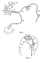
Figure 1 shows implantable neurological drug delivery apparatus that includes a fluid router of the present invention, -
Figure 2 illustrates the device offigure 1 implanted in a subject, -
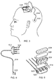
Figure 3 shows a further implantable neurological drug delivery apparatus, -
Figure 4 shows the air/bacterial filter and percutaneous drug delivery port of the apparatus offigure 3 , -
Figure 5 is an exploded view of the air/bacterial filter shown infigures 3 and 4 , -
Figure 6 shows a further implantable neurological drug delivery apparatus, -
Figure 7 illustrates a further implantable neurological drug delivery apparatus having a separate filter unit, -
Figure 8 shows a catheter device having an integral air vent, -
Figure 9 shows a cut away view of the catheter device offigure 8 , and -
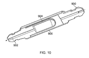
Figure 10 shows an in-line fluid router having an air vent. - Referring to
figure 1 , implantable neurological drug delivery apparatus is shown. The apparatus comprises aconstant pressure pump 2 that includes an internal reservoir and has an outlet 4 connected to the first end of a singlelumen supply tube 6. Although aconstant pressure pump 2 is shown, it should be noted that any implantable pump (e.g. a constant or programmable flow rate pump) can be employed. The second end ofthesupply tube 6 is connectable to the inlet 8 of aport unit 10. Theport unit 10 comprises two outlets that are linked to the two inlets of arouter unit 12 by a dual-lumen supply tube 14. Therouter unit 12 comprises twooutlets 16, each in fluid communication with a respective lumen of thesupply tube 14, that are each connectable to aneurological catheter device 18. - The
port unit 10 comprises a subcutaneous portion 20 and apercutaneous portion 22 that has anextracorporeal surface 24. The subcutaneous portion 20 is suitable for at least partial insertion into an appropriately shaped recess formed in the skull. In particular, the subcutaneous portion 20 is coated with a material that promotes biointegration with bone after implantation and will thus become secured to the skull without the need for bone screws or the like. In other words, the subcutaneous portion 20 is osseointegrating (also termed osteointegrating). In this example, the coating provided on the external surface of the subcutaneous portion 20 comprises plasma sprayed titanium combined with hydroxy-apatite. Other coatings or surface finishes may be provided to produce a similar effect. - The subcutaneous portion 20 may be formed as a single component but comprises three discrete functional parts. In particular, a first substantially
cylindrical part 26 of the subcutaneous portion 20 is connected to a second substantiallycylindrical part 28 by an elongate joiningsection 30. As will be described in more detail below with reference tofigure 3 , the second substantiallycylindrical part 28 has an inlet 8 for receiving carrier fluid from the pump outlet 4 and an exit for a dual-lumen supply tube 14 that comprise a separate lumen for supplying fluid to each of the twocatheters 18 via therouter unit 12. The first substantiallycylindrical part 26 is also attachable to thepercutaneous portion 22 thereby allowing external access to the separate fluidic pathways to the twocatheter devices 18. In particular, theextracorporeal surface 24 comprises two sealed access ports that permit fluid (e.g. a drug or other therapeutic agent) to be injected into the fluid stream that runs from thepump 2 to thecatheter devices 18. - An external
fluid connector unit 23 is also provided that is releasably attachable to theextracorporeal surface 24 of thepercutaneous portion 22. When theconnector unit 23 is attached or mated with theport unit 10, a pair of protruding needles 29 penetrate the seal and thereby provide separate fluidic access to the two ports of theport unit 10. The needles of thefluid connector unit 23 maybe separately connected to different channels of anexternal drug pump 27 or individual pumps via amulti-lumen tube 25. In this manner, thefluid connector unit 23 provides separate fluidic access to the different ports of theport unit 10 to enable the delivery of therapeutic agents or the like to thecatheter devices 18. Thefluid connector unit 23 may be attachable to theextracorporeal surface 24 in only one orientation to ensure the same needle always accesses the same port. A locking mechanism may also be provided to lock thefluid connector unit 23 to theextracorporeal surface 24 as and when required. - The first substantially
cylindrical part 26 is connected to the second substantiallycylindrical part 28 by the elongate joiningsection 30. The elongate joiningsection 30 comprises multiple lumens (in this case three) that provide the necessary fluidic pathways between the first and second substantiallycylindrical parts section 30 has the benefit of reducing the infection risk. Infection risk is further reduced by spacing theport unit 10 apart from therouter unit 12. The port unit and the various advantages thereof are described in more detail in Applicant's co-pending PCT application filed on the same day as the present application and also claiming priority from British patent application No.1002370.3 - Referring to
figure 2 , the drug delivery apparatus described with reference tofigure 1 is illustrated when implanted in the body. Theconstant pressure pump 2, which may comprise a diaphragm pump of known type, is not shown infigure 2 but is implanted in the abdomen. Thesupply tube 6 running from thepump 2 is tunnelled under the skin to the head of the subject. Theport unit 10 is affixed within an appropriately dimensioned recess formed in the bone ofthe skull adjacent the ear. Thesupply tube 6 is connected to the inlet 8 of theport unit 10 and the dual-lumen supply tube 14 exiting theport unit 10 is subcutaneously tunnelled under the scalp to therouter unit 12. Therouter unit 12 is secured to the skull, for example using bone screws, in the vicinity of the point where thecatheter devices 18 pass through holes in the skull and enter the brain parenchyma. - The
constant pressure pump 2 contains a reservoir that stores a carrier fluid, such as saline (e.g. buffered saline) or artificial cerebrospinal fluid (CSF). Thepump 2 maybe refillable in a known manner by percutaneous injection into a refill port provided on a surface of thepump 2. After implantation, thepump 2 supplies carrier fluid under pressure to theport unit 10 via thesupply tube 6. Theport unit 10 is arranged to continuously direct a small flow of carrier fluid to each of thecatheter devices 18 via the dual-lumen supply tube 14 androuter unit 12. Thedistal end 40 of eachcatheter device 18 is accurately positioned within the brain parenchyma at a required target site. Examples of suitable catheter devices are described inWO03/077785 US6609020 andWO03/077784 - For the majority ofthe time after implantation, the drug delivery apparatus is arranged to pump small volumes of carrier fluid into the brain parenchyma via the
catheter devices 18. The constant, or substantially constant, flow of carrier fluid reduces the chance of thecatheter devices 18 becoming occluded due to tissue in-growth. This allows the chronic implantation of catheter devices that include fine tubes having an outer diameter of less than 0.25mm. When the delivery of therapeutic agents is required, theextracorporeal surface 24 of thepercutaneous portion 22 of theport unit 10 provides separate access to the fluidic pathways to eachcatheter device 18 and thus permits the required dosage of therapeutic agent to be delivered to the target site(s). Such delivery of therapeutic agent may be performed continuously (e.g. over a period of a few hours or days) through each catheter in parallel. Alternatively, the delivery of therapeutic agent maybe performed serially (e.g. through each catheter in turn) to minimise any side effects associated with the delivered agent. - For many years, fully implantable drug delivery systems have been preferred for neurological applications to minimise the chances of an infection bypassing the blood-brain barrier and entering the brain parenchyma at the point the barrier is penetrated by a catheter. Such fully implantable system have however been found to have a number of disadvantages; for example, the storage capacity can be limited and problems often arise delivering drugs that have a short shelf-life or need to be stored in a certain environment (e.g. at a certain temperature). The use of a single implanted pump also does not provide the flow control that is needed when delivering fluid in precise volumes to different site using multiple catheters. It can also be difficult to access a refill port of a subcutaneously implanted pump, especially in obese patients, and any subcutaneous leakage of therapeutic agent can provoke an immune response to such agents. Although percutaneous access ports or refill ports have been proposed previously, such ports tend to be implantable in the torso, thereby requiring long lengths of supply tubing that increase the dead volume of the system. This additional dead volume can reduce the control over drug delivery thereby reducing treatment efficacy in certain circumstances.
- The drug delivery apparatus illustrated in
figures 1 and 2 includes aport unit 10 that attached to the skull, but the apparatus is configured such that the inclusion of thepercutaneous portion 22 does not introduce an unacceptable increase in the risk of an infection bypassing the blood-brain barrier. A number of features of the apparatus minimise this infection risk and some or all of such features may be included in the apparatus as required. - The subcutaneous portion 20 of the
port unit 10 comprises a first substantiallycylindrical part 26 that is connected to the second substantiallycylindrical part 28 by the elongate joiningsection 30. As explained below, the majority ofthe subcutaneous portion 20 is located in a recess formed in the skull bone. In particular, the majority of the elongate joiningsection 30 is buried within the slot or recess formed in the skull. Preferably, the elongate joiningsection 30 is sub-flush to the outer surface of the skull bone and bone chipping or the like are placed on top of the elongate joiningsection 30 after implantation. This allows bone to regrow over the top of the elongate joiningsection 30 after implantation. After such bone growth, the first substantiallycylindrical part 26 is separated from the second substantiallycylindrical part 28 by a region that is buried within the skull bone. This acts as a infection barrier between the supply tube connections and the percutaneous part of theport unit 10 where infection is most likely to occur. In other words, the arrangement reduces the chance of any infection that arises at the interface between the skin and the protrudingpercutaneous portion 22 from passing to thesupply tube 14 and migrating along the outer surfaces of the various tubes that lead to the catheter devices that bypass the blood-brain barrier. Furthermore, the size ofthe percutaneous part of theport unit 10 is minimised thereby reducing the size of incision required thereby further reducing the infection risk. - In addition, it can be seen that the
router unit 12 is located away from theport unit 10. In this example, therouter unit 12 is separated from theport unit 10 by about 15cm of dual-lumen tubing 14. As noted above the most likely infection site is the interface between the skin and thepercutaneous portion 22 of theport unit 10. Providing therouter unit 12 between the tubing from theport unit 10 and thecatheter devices 18 thus introduces a further barrier to infection. - Bacterial filters may be provided within the apparatus to remove any bacteria present in the carrier fluid or in the therapeutic agent that is delivered. A bacterial filter may, for example, be located in the port unit 10 (e.g. in the second substantially cylindrical part 28) and/or in the
router unit 12. Thepump 2 may also or alternatively include a bacterial filter. The apparatus may also comprise an air filter to remove any air bubbles present in the fluid delivered to the brain. Such air bubbles are most likely to arise at connections between tubes or at the point ofinfusion of therapeutic agent into theport unit 10. In this example, the air filter is located in therouter unit 12 so that it is close to thecatheter devices 18 thereby removing as much air from the apparatus as possible. Alternatively, or additionally, such air filters may be provided in theport unit 10, for example in the second substantiallycylindrical part 28, or as part of the catheter device. Air extracted from the fluid by the air filters may be released into the body where it is absorbed. Alternatively, an air return path may be provided to outside of the body via theport unit 10 andconnector 23. -
Figures 3 to 5 show further neurological apparatus that comprises aport unit 510, asupply tube 514, arouter unit 512 and fourcatheter devices 518. In particular,figure 3 shows the apparatus implanted in a subject,figure 4 illustrates the apparatus prior to implantation andfigure 5 show the components of the filter unit in more detail. - Referring to
figures 3 and 4 , it can be seen how theport unit 510 is connected to therouter unit 512 by thesupply tube 514. Thecatheter devices 518 are each linked to an outlet of therouter unit 512 that provides an air filtering function. - Referring to
figure 5 , the structure of therouter unit 512 is shown in more detail. Therouter unit 512 comprises a fourchamber outflow portion 520, a hydrophilic (bacterial)filter 522, a fourchamber inflow portion 524, a hydrophobic (gas permeable)filter 526 and adiaphragm membrane 528. As described in more detail below, fluid passed to therouter unit 512 through the four lumens of thesupply tube 514 is separately filtered and output via outlets 530 to therespective catheter devices 518. In other words, each fluid path through the router unit is separately filtered and there is no mixing of the fluid that is routed to thedifferent catheter devices 518. - In operation, fluid from each lumen of the
supply tube 514 passes to a respective one ofthe inflow chambers of theinflow portion 524. The liquid ofthe fluid is attracted to thehydrophilic filter 522 and passes through thathydrophilic filter 522 into the associated outflow chamber of theoutflow portion 520. Gas (e.g. air) does not pass through thehydrophilic filter 522. Fluid from each chamber oftheoutflow portion 520 passes to an outlet 530 that is in turn connected to acatheter device 518. Thehydrophobic filter 526 acts as a barrier to liquid, but allows any gas (e.g. air) bubbles to pass through it. Gas (e.g. air) is thus removed from the fluid and is allowed to dissipate through thediaphragm membrane 528 into the body. Thehydrophilic filter 522 may also be configured to provide a bacterial filtration function. - As can be seen from figure 13, the
router unit 512 is located as close to thecatheter devices 518 as possible. This ensures air removal is performed as far downstream as possible thereby minimising the amount of air that is present in the fluid expelled from thecatheter devices 518. In particular, the air filtration is performed away from theport unit 510 and the majority of the tube connections that could introduce air. - Referring to
figure 6 , a further embodiment of neurological apparatus of the present invention is shown. The apparatus comprises an abdominally implantableconstant pressure pump 602, apercutaneous port unit 610, arouter unit 612 andcatheter device 618. A singlelumen supply tube 606 supplies carrier fluid from thepump 602 to therouter unit 612. A fourlumen supply tube 614 provide four separate fluid pathways from theport unit 610 to therouter unit 612. Theport unit 610 is preferably a port unit of the type described with reference tofigure 4 . The apparatus is arranged so that a flow of fluid supplied by theabdominal pump 602 is continuously pumped, at a low flow rate, to thecatheter devices 618 to prevent occlusion of such devices. Fluid containing a therapeutic agent may also be pumped into theport unit 610 and directed to eachcatheter device 618 via therouter unit 612. Therouter unit 612 includes a bacterial filter and/or an air filter. -
Figure 7 illustrates a variant ofthe device described with reference tofigure 6 . Carrier fluid from anabdominal pump 602 is pumped to afilter unit 620 via a singlelumen supply tube 606. Thefilter unit 620 splits the received carrier fluid into four streams that are routed into the four lumens at the proximal end of thesupply tube 622. At the distal end of thesupply tube 622, the four lumens separate into four separate tubes that are each connected to acatheter device 618. Theport unit 610 is connected to thefilter unit 620 by a fourlumen supply tube 624 and provides four separate fluidic links to the four separate fluid streams through thefilter unit 620. Therapeutic agent may thus be pumped to any one of thecatheter devices 618 from theport unit 610. - Referring next to
figures 8 to 9 , a catheter device is illustrated in which a fluid router comprising an air vent is located in the catheter head. This enables gas (e.g. air) to be separated from the liquid being delivered at a point that is even closer to the point of delivery. -
Figure 8 shows a catheter device that comprises asupply tube 800, a filtertop plate 802 having anaperture 804 formed therein, a hydrophobic filter membrane (gas vent) 806, a filter bodymiddle section 808, a bacteria retentivehydrophilic filter membrane 810, afilter base section 812 and anfine tube 814 for insertion into the brain parenchyma. The various components of the catheter are also shown in the cut-away view offigure 9 , where theinternal chamber 816 can also be seen. - Fluid (typically a liquid that contains unwanted air bubbles and bacteria) is supplied under pressure to the catheter device via the
supply tube 800 and enters thechamber 816. Liquid exits the chamber via the hydrophilic filter membrane 810 (noting any bacteria in the fluid are retained by the filter membrane 810) and passes into thefine tube 814. This liquid is then expelled from the distal end of thefine tube 814 to the desired site in the body. Any air bubbles contained in the fluid collect at, and diffuse through, thehydrophobic filter membrane 806. The air then exits the device via theaperture 804 in the filtertop plate 802. The relatively small amount of air that is vented from the fluid is then simply absorbed naturally by the body. - The catheter device alone may be inserted into the brain parenchyma or the catheter may be inserted via a previously implanted guide tube. Once implanted, the catheter device may be subcutaneously buried and either used periodically or continuously to deliver therapeutic agents directly to the brain parenchyma. Guide tubes and associated methods for inserting neurosurgical catheters are described in
US6609020 andWO2003/077785 . A skull mount for use when inserting catheter devices is also described inWO2009/047494 . The methods described previously may also be used to implant the catheter device described herein with reference tofigures 8 and 9 . - It is convenient for the gas vent to be included in a fluid router unit having multiple inlets/outlets or the head of catheter device as described above. It would, however, be appreciated by the skilled person that the gas vent could be included in any part of an implantable apparatus or as a standalone implantable component.
- Referring to
figure 10 , an implantable in-line bubble filter device is illustrated. The device comprises aninlet 900, anoutlet 902, a hydrophilic (bacteria retaining)membrane 904 and an outer gas permeable (hydrophobic)membrane 906 fabricated from expanded polytetrafluroethylene (ePTFE). ePTFE has the additional advantage that it can be processed so that cells do not grow or adhere to it. Although not shown, an outer protective mesh may be provided. The device may be included as part of an implantable drug delivery system. - The skilled person would appreciate that, in addition to the examples outlined above, the gas vents of the present invention may be implemented using a variety of different materials. For example, polyvinylidene fluoride (PVDF) or polyethersulfone (PES) membranes may be provided that can be either hydrophobic or hydrophilic. Sintered titanium, for example plugs, cups or tubes of porous titanium, may also be used for bacteria retention. The various materials outlined above should therefore be in no way seen as limiting the scope of the present invention. Similarly, the gas vent may be incorporated into any medical, implantable, device and the various embodiments presented above are in no way intended to limit the scope of the invention.
Claims (12)
- An implantable fluid router (12;512) comprising one or more inlets (514), one or more outlets (530) and at least one gas vent for removing gas from liquid routed from the one or more inlets (514) to the one or more outlets (530), characterised in that each gas vent includes a chamber that comprises a gas permeable membrane (526) through which gas present in liquid routed through the chamber may pass and a hydrophilic material (522) through which liquid passes when routed through that chamber.
- An implantable fluid router according to claim 1, comprising a plurality of inlets (514), a plurality of outlets (530) and a plurality of separate liquid pathways between the plurality of inlets (514) and the plurality of outlets (530).
- An implantable fluid router according to claim 2, comprising a plurality of gas vents, wherein each liquid pathway comprises a separate gas vent.
- An implantable fluid router according to claim 1, comprising one inlet, one outlet and one gas vent in the liquid pathway between the inlet and the outlet.
- An implantable fluid router according to claim 4, provided in the form of catheter head.
- An implantable fluid router according to any preceding claim, wherein each gas vent is arranged to vent gas into the body of the subject in which the device is implanted.
- An implantable fluid router according to any preceding claim, wherein the gas permeable membrane (526) is hydrophobic.
- An implantable fluid router according to any preceding claim, wherein the gas permeable membrane (526) comprises expanded polytetraflurothylene (ePTFE).
- An implantable fluid router according to any preceding claim, wherein the hydrophilic material (522) is bacteria retentive and thereby also acts as a bacterial filter.
- An implantable fluid router according to any preceding claim, wherein the liquid routed from the one or more inlets (514) to the one or more outlets (530) comprises a therapeutic agent.
- A neurosurgical catheter comprising an implantable router unit according to any preceding claim.
- A neurosurgical kit comprising an implantable router (12;512) according to any one of claims 1 to 10 and at least one of a neurosurgical catheter (40), a supply tube (6;514) and a percutaneous access device (10).
Applications Claiming Priority (2)
| Application Number | Priority Date | Filing Date | Title |
|---|---|---|---|
| GBGB1002370.3A GB201002370D0 (en) | 2010-02-12 | 2010-02-12 | Percutaneous drug delivery apparatus |
| PCT/GB2011/000182 WO2011098768A1 (en) | 2010-02-12 | 2011-02-11 | Implantable fluid router |
Publications (2)
| Publication Number | Publication Date |
|---|---|
| EP2533829A1 EP2533829A1 (en) | 2012-12-19 |
| EP2533829B1 true EP2533829B1 (en) | 2016-10-12 |
Family
ID=42110610
Family Applications (3)
| Application Number | Title | Priority Date | Filing Date |
|---|---|---|---|
| EP11706900.5A Active EP2533830B1 (en) | 2010-02-12 | 2011-02-11 | Percutaneous drug delivery apparatus |
| EP21156072.7A Active EP3900758B1 (en) | 2010-02-12 | 2011-02-11 | Percutaneous drug delivery apparatus |
| EP11706899.9A Active EP2533829B1 (en) | 2010-02-12 | 2011-02-11 | Implantable fluid router |
Family Applications Before (2)
| Application Number | Title | Priority Date | Filing Date |
|---|---|---|---|
| EP11706900.5A Active EP2533830B1 (en) | 2010-02-12 | 2011-02-11 | Percutaneous drug delivery apparatus |
| EP21156072.7A Active EP3900758B1 (en) | 2010-02-12 | 2011-02-11 | Percutaneous drug delivery apparatus |
Country Status (7)
| Country | Link |
|---|---|
| US (4) | US10507316B2 (en) |
| EP (3) | EP2533830B1 (en) |
| JP (3) | JP5801323B2 (en) |
| CN (4) | CN102753217B (en) |
| ES (1) | ES2864579T3 (en) |
| GB (1) | GB201002370D0 (en) |
| WO (2) | WO2011098768A1 (en) |
Families Citing this family (79)
| Publication number | Priority date | Publication date | Assignee | Title |
|---|---|---|---|---|
| AU2002952691A0 (en) | 2002-11-15 | 2002-11-28 | Sunshine Heart Company Pty Ltd | Heart assist device utilising aortic deformation |
| AU2004284842B2 (en) | 2003-10-31 | 2010-03-04 | Nuwellis, Inc. | Synchronisation control system |
| DE602005023458D1 (en) | 2005-09-12 | 2010-10-21 | Unomedical As | A delivery system for an infusion set having first and second spring units |
| GB0623395D0 (en) | 2006-11-23 | 2007-01-03 | Renishaw Plc | Port |
| GB201002370D0 (en) | 2010-02-12 | 2010-03-31 | Renishaw Ireland Ltd | Percutaneous drug delivery apparatus |
| KR20130018783A (en) | 2010-03-30 | 2013-02-25 | 우노메디컬 에이/에스 | Medical device |
| JP5918213B2 (en) | 2010-04-02 | 2016-05-18 | サンシャイン・ハート・カンパニー・ピーティーワイ・リミテッド | Composite cardiac assist system, method and apparatus |
| PL2558154T3 (en) | 2010-04-16 | 2020-11-30 | Clearpoint Neuro, Inc. | Mri surgical systems including mri-compatible surgical cannulae for transferring a substance to and/or from a patient |
| US10194938B2 (en) | 2011-03-14 | 2019-02-05 | UnoMedical, AS | Inserter system with transport protection |
| EP3881876A1 (en) | 2011-08-01 | 2021-09-22 | Alcyone Lifesciences, Inc. | Microfluidic drug delivery devices |
| WO2013050277A1 (en) | 2011-10-05 | 2013-04-11 | Unomedical A/S | Inserter for simultaneous insertion of multiple transcutaneous parts |
| EP2583715A1 (en) | 2011-10-19 | 2013-04-24 | Unomedical A/S | Infusion tube system and method for manufacture |
| GB201202093D0 (en) | 2012-02-07 | 2012-03-21 | Renishaw Ireland Ltd | Drug storage apparatus |
| GB201202091D0 (en) * | 2012-02-07 | 2012-03-21 | Renishaw Ireland Ltd | Drug delivery apparatus |
| GB201202094D0 (en) | 2012-02-07 | 2012-03-21 | Renishaw Ireland Ltd | Medical apparatus |
| GB201204263D0 (en) | 2012-03-12 | 2012-04-25 | Renishaw Plc | Giloma treatment |
| CN104334229A (en) * | 2012-05-22 | 2015-02-04 | 阳光心脏有限公司 | Methods, systems, and devices relating to a removable percutaneous interface line |
| GB201217606D0 (en) | 2012-10-02 | 2012-11-14 | Renishaw Plc | Neurosurgical device and method |
| CA2895509C (en) | 2012-12-18 | 2021-08-17 | Alcyone Lifesciences, Inc. | Systems and methods for reducing or preventing backflow in a delivery system |
| GB201308917D0 (en) | 2013-05-17 | 2013-07-03 | Renishaw Plc | Delivery |
| JP2016522069A (en) | 2013-06-17 | 2016-07-28 | アルキオーネ・ライフサイエンシズ・インコーポレイテッドAlcyone Lifesciences, Inc. | Method and apparatus for protecting catheter tip and stereotaxic fixture for microcatheter |
| JP6498670B2 (en) * | 2013-07-31 | 2019-04-10 | アルキオーネ・ライフサイエンシズ・インコーポレイテッドAlcyone Lifesciences, Inc. | Systems and methods for drug delivery, therapy, and monitoring |
| EP3027258B1 (en) * | 2013-08-02 | 2020-04-22 | Withers, Teresa Kathryn | Catheter placement device |
| US9891296B2 (en) | 2013-09-13 | 2018-02-13 | MRI Interventions, Inc. | Intrabody fluid transfer devices, systems and methods |
| CA3059017C (en) | 2013-09-24 | 2021-05-25 | Giner Life Sciences, Inc. | System for gas treatment of a cell implant |
| US9968765B2 (en) | 2014-07-21 | 2018-05-15 | The Cleveland Clinic Foundation | Convection enhanced delivery device and system |
| US9907941B2 (en) | 2014-07-21 | 2018-03-06 | The Cleveland Clinic Foundation | Convection enhanced delivery device and system |
| US10806396B2 (en) | 2015-01-26 | 2020-10-20 | Alcyone Lifesciences, Inc. | Drug delivery methods with tracer |
| US10716891B2 (en) | 2015-04-07 | 2020-07-21 | Isaab Innovations Llc | Implantable fluid delivery system |
| US11207461B2 (en) * | 2015-07-30 | 2021-12-28 | Anoop U. R | Drug delivery system and method for controlled and continuous delivery of drugs into the brain by bypassing the blood brain barrier |
| WO2017017543A1 (en) * | 2015-07-30 | 2017-02-02 | U R Anoop | Drug delivery system and method for controlled and continuous delivery of drugs into the brain by bypassing the blood brain barrier |
| US10531882B2 (en) | 2016-01-04 | 2020-01-14 | Alcyone Lifesciences, Inc. | Methods and devices for treating stroke |
| US11357912B2 (en) | 2016-01-19 | 2022-06-14 | Unomedical A/S | Cannula and infusion devices |
| WO2017142698A1 (en) | 2016-02-17 | 2017-08-24 | MRI Interventions, Inc. | Intrabody surgical fluid transfer assemblies with adjustable exposed cannula to needle tip length, related systems and methods |
| EP3243549A1 (en) | 2016-05-12 | 2017-11-15 | Renishaw plc | Percutaneous access apparatus |
| EP3243548A1 (en) * | 2016-05-12 | 2017-11-15 | Renishaw plc | Priming device |
| US11324936B2 (en) | 2016-05-16 | 2022-05-10 | The Cleveland Clinic Foundation | System and method for delivering fluid internally of a patient's body |
| JP6993003B2 (en) * | 2016-11-15 | 2022-01-13 | ガイナー ライフ サイエンシズ,インク. | Percutaneous gas diffuser suitable for use with subcutaneous implants |
| CN113730789A (en) * | 2016-12-16 | 2021-12-03 | 索伦托治疗有限公司 | Fluid delivery device with suction mechanism and method of use |
| EP3554619B1 (en) | 2016-12-16 | 2021-10-20 | Sorrento Therapeutics, Inc. | Fluid delivery apparatus and method of assembly |
| WO2018111620A2 (en) | 2016-12-16 | 2018-06-21 | Kimberly-Clark Worldwide, Inc. | Method for administering a medicament suitable for treating a migraine or cluster headache |
| CA3047258A1 (en) | 2016-12-16 | 2018-06-21 | Sorrento Therapeutics, Inc. | A fluid delivery apparatus having a controller assembly and method of use |
| ES2912537T3 (en) | 2016-12-16 | 2022-05-26 | Sorrento Therapeutics Inc | Support band for a fluid administration apparatus and method of use |
| KR102590629B1 (en) | 2016-12-16 | 2023-10-19 | 소렌토 쎄라퓨틱스, 인코포레이티드 | Application devices for fluid transfer devices and methods of using the same |
| EP3618916A4 (en) * | 2017-05-04 | 2021-04-14 | Giner Life Sciences, Inc. | IMPLANTABLE DEVICE FOR RUGGED GAS DISTRIBUTION AND PROCESSES, SYSTEMS AND DEVICES USING IT |
| US11724033B2 (en) * | 2018-04-10 | 2023-08-15 | Pain Away Solutions, LLC | Method and apparatus for delivering drugs to the spine of a patient, and/or for delivering other materials and/or devices to the spine of a patient |
| JP7517996B2 (en) * | 2018-04-27 | 2024-07-17 | ベクトン・ディキンソン・アンド・カンパニー | Delivery Devices and Sorbents |
| US11253237B2 (en) | 2018-05-09 | 2022-02-22 | Clearpoint Neuro, Inc. | MRI compatible intrabody fluid transfer systems and related devices and methods |
| WO2019216953A1 (en) | 2018-05-09 | 2019-11-14 | MRI Interventions, Inc. | Mri compatible intrabody fluid transfer systems and related devices and methods |
| GB201812746D0 (en) | 2018-08-06 | 2018-09-19 | Gill Steven S | Method |
| CA3112773A1 (en) * | 2018-09-14 | 2020-03-19 | John Mansell | Implantable nerve blocking intervention |
| JP7232440B2 (en) | 2018-10-22 | 2023-03-03 | 株式会社ハイレックスコーポレーション | Fixing device |
| PL3886975T3 (en) * | 2018-11-26 | 2024-06-24 | Focal Medical, Inc. | Implantable reservoir for use with a medical device and emergency drug delivery system |
| EP3972672A4 (en) | 2019-05-20 | 2023-06-21 | Unomedical A/S | ROTATING INFUSION DEVICE AND METHOD THEREOF |
| AU2020337896A1 (en) * | 2019-08-28 | 2022-03-17 | Alcyone Therapeutics, Inc. | Fluid delivery system |
| EP4048174B1 (en) * | 2019-10-01 | 2025-12-03 | Pain Away Solutions, LLC | System for delivering drugs to the spine of a patient, and/or for delivering other materials and/or devices to the spine of a patient |
| US11684750B2 (en) | 2019-10-08 | 2023-06-27 | Clearpoint Neuro, Inc. | Extension tube assembly and related medical fluid transfer systems and methods |
| EP3808296B1 (en) * | 2019-10-17 | 2021-12-22 | Heraeus Medical GmbH | Device for local application of and / or for rinsing with fluids |
| GB202009981D0 (en) | 2020-06-30 | 2020-08-12 | Xced Llp | Method |
| US12551669B2 (en) | 2020-07-15 | 2026-02-17 | Biogen Ma Inc. | Medical system including two access ports |
| IL299904B1 (en) * | 2020-07-20 | 2026-05-01 | Cerebral Therapeutics Inc | Fluid catheter device for recording brain state |
| WO2022036217A1 (en) | 2020-08-13 | 2022-02-17 | The Trustees Of Columbia University In The City Of New York | Systems and methods for blood-brain barrier opening and cavitation imaging using a diagnostic imaging array |
| KR102956094B1 (en) * | 2020-08-13 | 2026-04-27 | 크라니유에스 엘엘씨 | High-profile anatomical-specific craniofacial implants for combined hard and soft tissue reconstruction using embedded technology for drug delivery |
| US12551613B2 (en) | 2020-10-30 | 2026-02-17 | Medtronic, Inc. | Implantable drug delivery port |
| US11931545B2 (en) | 2020-10-30 | 2024-03-19 | Medtronic, Inc. | Drug infusion port |
| US11992642B2 (en) * | 2020-10-30 | 2024-05-28 | Medtronic, Inc. | Implantable medical device for delivery of pharmacological agents to the deep brain structures |
| US11745003B2 (en) | 2020-10-30 | 2023-09-05 | Medtronic, Inc. | Implantable access port with one-directional filter |
| US12226609B2 (en) | 2020-12-16 | 2025-02-18 | Medtronic, Inc. | Method to detect inadvertent delivery of drug to a subcutaneous pocket |
| CA3216973A1 (en) * | 2021-04-30 | 2022-11-03 | Neurochase Technologies Limited | Implantable guide device |
| CN113289137B (en) * | 2021-05-24 | 2022-10-18 | 枣庄市肿瘤医院(枣庄市胸科医院) | Implantable medical device based on self-sealing plug structure |
| GB202109503D0 (en) | 2021-07-01 | 2021-08-18 | Xced Llp | Method |
| US12605537B2 (en) | 2022-02-15 | 2026-04-21 | Biogen Ma Inc. | Implantable medical device for use with or having recording electrode |
| GB202202719D0 (en) | 2022-02-28 | 2022-04-13 | Neurochase Tech Ltd | Port |
| US12706887B2 (en) | 2022-10-20 | 2026-08-11 | Precision Neuroscience Corporation | Secure interfaces for neural devices |
| US12530080B2 (en) | 2022-10-20 | 2026-01-20 | Precision Neuroscience Corporation | Systems and methods for self-calibrating neural decoding |
| EP4673051A1 (en) | 2023-02-28 | 2026-01-07 | Precision Neuroscience Corporation | Data compression for neural systems |
| EP4788212A1 (en) | 2023-10-06 | 2026-08-12 | Precision Neuroscience Corporation | Systems and methods for visualizing brain activity in real time at high spatial and temporal resolution |
| US12645297B2 (en) | 2024-02-01 | 2026-06-02 | Precision Neuroscience Corporation | Interposer for high-density and high-channel count neural interface |
| US12548570B1 (en) | 2025-02-25 | 2026-02-10 | Precision Neuroscience Corporation | Neural foundation models for brain-computer interface |
Family Cites Families (115)
| Publication number | Priority date | Publication date | Assignee | Title |
|---|---|---|---|---|
| US3452366A (en) | 1966-06-21 | 1969-07-01 | Avco Corp | Percutaneous conduit and connector |
| US3618637A (en) * | 1970-02-04 | 1971-11-09 | Deseret Pharma | Rotary mixing valve |
| US4013074A (en) | 1974-06-21 | 1977-03-22 | Siposs George G | Implantable medication-dispensing device |
| US4354506A (en) * | 1980-01-17 | 1982-10-19 | Naganokeiki Seisakujo Company, Ltd. | Intracranial pressure gauge |
| US4692147A (en) | 1980-04-02 | 1987-09-08 | Medtronic, Inc. | Drug administration device |
| DE3138320A1 (en) * | 1981-09-25 | 1983-04-14 | Siemens AG, 1000 Berlin und 8000 München | INFUSION DEVICE PROVIDED FOR IMPLANTATION IN A LIVING BODY |
| US4897081A (en) | 1984-05-25 | 1990-01-30 | Thermedics Inc. | Percutaneous access device |
| US4634422A (en) | 1984-05-31 | 1987-01-06 | Adrian Kantrowitz | Percutaneous access device and method for implanting same |
| US4578063A (en) | 1984-09-14 | 1986-03-25 | W. L. Gore & Assoc., Inc. | Central venous catheter |
| US4581012A (en) | 1984-12-05 | 1986-04-08 | I-Flow Corporation | Multilumen catheter set |
| US4822339A (en) * | 1984-12-06 | 1989-04-18 | Controlled Release Technologies, Inc. | Therapeutic agent delivery system and method |
| GB8527646D0 (en) * | 1985-11-08 | 1985-12-11 | Cox J A | Devices for sampling drainage |
| US4772263A (en) * | 1986-02-03 | 1988-09-20 | Regents Of The University Of Minnesota | Spring driven infusion pump |
| US4790826A (en) | 1986-03-28 | 1988-12-13 | Elftman Nancy W | Percutaneous access port |
| US5120313A (en) | 1986-03-28 | 1992-06-09 | Nancy W. Elftman | Method for measuring blood pressure in an animal or human using a percutaneous access port |
| US4695273A (en) | 1986-04-08 | 1987-09-22 | I-Flow Corporation | Multiple needle holder and subcutaneous multiple channel infusion port |
| US4705464A (en) | 1986-05-09 | 1987-11-10 | Surgidev Corporation | Medicine pump |
| FR2604907A1 (en) | 1986-10-01 | 1988-04-15 | Galtier Claude | IMPLANT HAVING A VASCULAR OR SPINAL CATHETER FOR PARENTERICALLY ASSISTED FOOD |
| SE465910B (en) * | 1988-01-28 | 1991-11-18 | Jan Axel Svensson | DEVICE FOR CONNECTING CATHETRES IN A SKIN REVIEW |
| SE8800467L (en) | 1988-02-12 | 1989-08-13 | Jan Axel Svensson | HUDGENOMGAANG |
| US4903707A (en) | 1988-04-22 | 1990-02-27 | Camino Laboratories | Ventricular catheter assembly |
| JP2732272B2 (en) | 1988-12-22 | 1998-03-25 | 株式会社アドバンス | Biological terminal structure |
| US5171216A (en) | 1989-08-28 | 1992-12-15 | Thermedics, Inc. | Multi-lumen catheter coupling |
| JPH03126438A (en) * | 1989-10-09 | 1991-05-29 | Olympus Optical Co Ltd | Skin terminal |
| JPH0693914B2 (en) | 1990-04-02 | 1994-11-24 | テルモ株式会社 | Chemical injection device |
| US5990382A (en) | 1990-08-29 | 1999-11-23 | Biomedical Enterprises, Inc. | Method and implant for surgical manipulation of bone |
| AU647856B2 (en) | 1990-12-28 | 1994-03-31 | Terumo Kabushiki Kaisha | Transfusion filtering device |
| US5122114A (en) | 1991-02-01 | 1992-06-16 | Board Of Regents, University Of Texas System | Method of using intramedullary catheter |
| US5318545A (en) | 1991-09-06 | 1994-06-07 | Device Labs, Inc. | Composite implantable biocompatible vascular access port device |
| FR2690625B1 (en) | 1992-04-29 | 1995-02-10 | Chronotec | Multi-chamber implantable access device and associated multi-needle device. |
| US5352207A (en) | 1992-05-18 | 1994-10-04 | Nussbaum Eric S | Ventricular drainage catheter with guard |
| US5423772A (en) * | 1993-08-13 | 1995-06-13 | Daig Corporation | Coronary sinus catheter |
| US5464446A (en) * | 1993-10-12 | 1995-11-07 | Medtronic, Inc. | Brain lead anchoring system |
| US20020133232A1 (en) | 1993-11-02 | 2002-09-19 | Ricci John L. | Microstructured dual sided membrane for tissue growth and regeneration |
| US5604976A (en) * | 1994-10-18 | 1997-02-25 | Pi Medical Corporation | Method of making percutaneous connector for multi-conductor electrical cables |
| DE69529572T2 (en) | 1994-11-10 | 2003-06-18 | The University Of Kentucky Research Foundation, Lexington | IMPLANTABLE REFILLABLE DEVICE WITH CONTROLLED RELEASE FOR ADMINISTERING MEDICINAL SUBSTANCES DIRECTLY ON AN INNER PART OF THE BODY |
| JPH08141088A (en) | 1994-11-24 | 1996-06-04 | Unitika Ltd | Valved cannula |
| US5954687A (en) | 1995-04-28 | 1999-09-21 | Medtronic, Inc. | Burr hole ring with catheter for use as an injection port |
| US5752930A (en) | 1995-04-28 | 1998-05-19 | Medtronic, Inc. | Implantable techniques for infusing equal volumes of agents to spaced sites |
| US5695490A (en) * | 1995-06-07 | 1997-12-09 | Strato/Infusaid, Inc. | Implantable treatment material device |
| US6605063B2 (en) | 1998-09-21 | 2003-08-12 | Gerald G. Bousquet | Transcutaneous access device |
| FR2750054B1 (en) | 1996-06-24 | 1998-10-16 | Hugueny Jean Marie | TRANSCUTANEOUS FLUID TRANSFER DEVICE |
| US5906596A (en) | 1996-11-26 | 1999-05-25 | Std Manufacturing | Percutaneous access device |
| US5833654A (en) | 1997-01-17 | 1998-11-10 | C. R. Bard, Inc. | Longitudinally aligned dual reservoir access port |
| US6086555A (en) * | 1997-01-17 | 2000-07-11 | C. R. Bard, Inc. | Dual reservoir vascular access port with two-piece housing and compound septum |
| US5833655A (en) | 1997-05-15 | 1998-11-10 | L. Vad Technology, Inc. | Percutaneous access device having removable turret assembly |
| US5916200A (en) | 1997-10-01 | 1999-06-29 | Walter Lorenz Surgical, Inc. | Apparatus and method for stabilization of a cranial shunt |
| US5843150A (en) * | 1997-10-08 | 1998-12-01 | Medtronic, Inc. | System and method for providing electrical and/or fluid treatment within a patient's brain |
| WO1999024097A1 (en) | 1997-11-12 | 1999-05-20 | Stereotaxis, Inc. | Intracranial bolt and method of placing and using an intracranial bolt to position a medical device |
| SE513670C2 (en) | 1997-12-18 | 2000-10-16 | Grogrunden Ab Nr 444 | Percutaneous bone anchored transducer |
| US6044304A (en) * | 1998-04-29 | 2000-03-28 | Medtronic, Inc. | Burr ring with integral lead/catheter fixation device |
| DE19820808C2 (en) | 1998-05-09 | 2000-11-02 | Wolfgang Fleckenstein | Insertion device for brain probes |
| DE29811529U1 (en) * | 1998-06-27 | 1999-11-25 | B. Braun Melsungen Ag, 34212 Melsungen | Filters for medical liquids |
| DE29817718U1 (en) * | 1998-10-05 | 1998-12-10 | CareMed Medical Produkte AG, 01109 Dresden | Infusion collector |
| US6013051A (en) * | 1998-10-22 | 2000-01-11 | Medtronic, Inc. | Filtered access port with filter bypass for accessing body fluid samples |
| US6134477A (en) | 1999-04-30 | 2000-10-17 | Medtronic, Inc. | Adjustable medical lead fixation system |
| US6471689B1 (en) | 1999-08-16 | 2002-10-29 | Thomas Jefferson University | Implantable drug delivery catheter system with capillary interface |
| GB9928248D0 (en) | 1999-12-01 | 2000-01-26 | Gill Steven S | An implantable guide tube for neurosurgery |
| US6356792B1 (en) | 2000-01-20 | 2002-03-12 | Electro Core Technologies, Llc | Skull mounted electrode lead securing assembly |
| JP2004538042A (en) | 2000-12-14 | 2004-12-24 | コントロール・デリバリー・システムズ | Implantable and refillable controlled release drug delivery device with port |
| IL157561A0 (en) | 2001-03-04 | 2004-03-28 | Sterling Medivations Inc | Infusion hub assembly and fluid line disconnect system |
| US6607504B2 (en) | 2001-06-29 | 2003-08-19 | Scimed Life Systems, Inc. | Percutaneous access |
| US7011647B2 (en) | 2001-07-13 | 2006-03-14 | Scimed Life Systems, Inc. | Introducer sheath |
| US20030023208A1 (en) | 2001-07-24 | 2003-01-30 | Osypka Thomas P. | Apparatus for vascular access |
| DE20115120U1 (en) | 2001-08-31 | 2002-03-07 | Disetronic Licensing Ag, Burgdorf | Implant with a surface structure |
| DE10143820B4 (en) | 2001-09-06 | 2004-05-06 | Disetronic Licensing Ag | Membrane, membrane-cannula combination and connection device |
| WO2003020343A1 (en) | 2001-08-31 | 2003-03-13 | Disetronic Licensing Ag | Connecting device for a percutaneously implanted port and port system comprising the connecting device |
| US8075630B2 (en) | 2001-09-06 | 2011-12-13 | Bio-Lok International, Inc. | Transcutaneous port having micro-textured surfaces for tissue and bone integration |
| US7108680B2 (en) | 2002-03-06 | 2006-09-19 | Codman & Shurtleff, Inc. | Closed-loop drug delivery system |
| US20030171738A1 (en) | 2002-03-06 | 2003-09-11 | Konieczynski David D. | Convection-enhanced drug delivery device and method of use |
| GB0205773D0 (en) | 2002-03-12 | 2002-04-24 | Gill Steven S | Clamp |
| GB0205772D0 (en) | 2002-03-12 | 2002-04-24 | Gill Steven S | Catheter |
| SE524157C2 (en) * | 2002-04-08 | 2004-07-06 | Transcutan Ab | Transcutaneous door device |
| GB2389791B (en) * | 2002-04-30 | 2006-12-13 | Steven Gill | Implantable drug delivery pump |
| EP1509278B1 (en) | 2002-05-22 | 2014-03-12 | Alfred E. Mann Foundation for Scientific Research | Implantable medication delivery device |
| US7479146B2 (en) | 2002-08-14 | 2009-01-20 | Boston Scientific Neuromodulation Corporation | Cranial burr hole plug and insertion tool |
| JP2004169628A (en) * | 2002-11-20 | 2004-06-17 | Mikuni Corp | Throttle device |
| US7824444B2 (en) | 2003-03-20 | 2010-11-02 | Spineco, Inc. | Expandable spherical spinal implant |
| AU2003901867A0 (en) | 2003-04-17 | 2003-05-08 | Cochlear Limited | Osseointegration fixation system for an implant |
| DE602004029026D1 (en) | 2003-05-27 | 2010-10-21 | Spinalmotion Inc | BELT PANTHEES FOR THE INTERVERTEBRALE INTRODUCTION |
| WO2004105839A1 (en) | 2003-05-29 | 2004-12-09 | Renishaw Plc | Implantable pump |
| US6916310B2 (en) | 2003-05-30 | 2005-07-12 | Codman & Shurtleff, Inc. | Percutaneous access device |
| US7320676B2 (en) * | 2003-10-02 | 2008-01-22 | Medtronic, Inc. | Pressure sensing in implantable medical devices |
| CN2684843Y (en) * | 2003-11-10 | 2005-03-16 | 马清刚 | Liquid medicine filter |
| US7981119B2 (en) | 2003-12-11 | 2011-07-19 | Advanced Neuromodulation Systems, Inc. | Electrical stimulation system and associated apparatus for securing an electrical stimulation lead in position in a person's brain |
| US7647097B2 (en) * | 2003-12-29 | 2010-01-12 | Braingate Co., Llc | Transcutaneous implant |
| WO2005079903A2 (en) | 2004-02-13 | 2005-09-01 | Medtronic, Inc. | Methods and apparatus for securing a therapy delivery device within a burr hole |
| WO2005106298A1 (en) | 2004-04-22 | 2005-11-10 | Medtronic, Inc. | Catheter systems having flow restrictors |
| US7604658B2 (en) | 2004-05-04 | 2009-10-20 | Codman & Shurtleff, Inc. | Multiple lumen sensor attachment |
| US20060217673A1 (en) | 2005-03-22 | 2006-09-28 | Schulze Dale R | Subcutaneous injection port with stabilizing elements |
| US7637892B2 (en) * | 2005-05-10 | 2009-12-29 | Palyon Medical (Bvi) Limited | Variable flow infusion pump system |
| CN2834581Y (en) | 2005-10-27 | 2006-11-08 | 浙江伏尔特医疗器械有限公司 | Medicinal liquid filter |
| WO2007087460A2 (en) * | 2006-01-30 | 2007-08-02 | Glenn Bradley J | Bone supported vascular access port |
| GB0603037D0 (en) | 2006-02-15 | 2006-03-29 | Renishaw Plc | Implantable fluid distribution device and a method of drug delivery |
| GB0604952D0 (en) | 2006-03-13 | 2006-04-19 | Renishaw Plc | A fluid connector for fluid delivery apparatus |
| GB0604929D0 (en) | 2006-03-13 | 2006-04-19 | Renishaw Plc | Method and apparatus for fluid delivery |
| US8221354B2 (en) * | 2006-04-27 | 2012-07-17 | Medtronic, Inc. | Infusion device with positive pressure elastic bladder reservoir |
| GB0616411D0 (en) | 2006-08-18 | 2006-09-27 | Renishaw Plc | Neurosurgical instruments |
| GB0623395D0 (en) | 2006-11-23 | 2007-01-03 | Renishaw Plc | Port |
| US7833204B2 (en) | 2007-05-14 | 2010-11-16 | Applied Medical Research | Intramedullary access or infusion devices |
| CN201088751Y (en) * | 2007-06-22 | 2008-07-23 | 黄金钟 | Self-exhaust filter for infusion |
| CA2701132A1 (en) | 2007-10-08 | 2009-04-16 | Renishaw (Ireland) Limited | Apparatus for stereotactic neurosurgery |
| EP2242534B1 (en) | 2008-01-22 | 2014-01-08 | Medtronic, Inc. | Burr hole anchors and systems |
| AU2009209515A1 (en) | 2008-01-28 | 2009-08-06 | Milux Holding Sa | Blood clot removal device, system, and method |
| US8336540B2 (en) * | 2008-02-19 | 2012-12-25 | Portaero, Inc. | Pneumostoma management device and method for treatment of chronic obstructive pulmonary disease |
| EP2092943A1 (en) | 2008-02-21 | 2009-08-26 | Universität Bern | Implantable access for removal and/or return of fluids |
| US8551044B2 (en) * | 2008-03-05 | 2013-10-08 | Flowonix Medical Incorporated | Multiple reservoir implantable drug infusion device and method |
| GB2459101A (en) | 2008-04-08 | 2009-10-14 | Epsom And St Helier University | Subcutaneous port and catheter |
| US8608729B2 (en) | 2008-04-18 | 2013-12-17 | Medtronic, Inc. | Implantable infusion device having filter |
| JP5154326B2 (en) * | 2008-07-28 | 2013-02-27 | 日本コヴィディエン株式会社 | Medical stopcock with cap |
| FR2939304B1 (en) | 2008-12-05 | 2012-03-30 | Pierre Sabin | CASE-INTERFACE ASSEMBLY FOR IMPLICATION IN A BONE WALL |
| US8323270B2 (en) * | 2009-10-19 | 2012-12-04 | Pharmaco-Kinesis Corporation | Enhanced method for delivering bevacizumab (avastin) into a brain tumor using an implanted magnetic breather pump |
| GB201002370D0 (en) | 2010-02-12 | 2010-03-31 | Renishaw Ireland Ltd | Percutaneous drug delivery apparatus |
| GB201202091D0 (en) | 2012-02-07 | 2012-03-21 | Renishaw Ireland Ltd | Drug delivery apparatus |
| GB201217606D0 (en) * | 2012-10-02 | 2012-11-14 | Renishaw Plc | Neurosurgical device and method |
-
2010
- 2010-02-12 GB GBGB1002370.3A patent/GB201002370D0/en not_active Ceased
-
2011
- 2011-02-11 JP JP2012552463A patent/JP5801323B2/en active Active
- 2011-02-11 CN CN201180009002.1A patent/CN102753217B/en active Active
- 2011-02-11 US US13/575,759 patent/US10507316B2/en active Active
- 2011-02-11 JP JP2012552462A patent/JP5826191B2/en not_active Expired - Fee Related
- 2011-02-11 WO PCT/GB2011/000182 patent/WO2011098768A1/en not_active Ceased
- 2011-02-11 CN CN201410772721.4A patent/CN104548284B/en active Active
- 2011-02-11 EP EP11706900.5A patent/EP2533830B1/en active Active
- 2011-02-11 EP EP21156072.7A patent/EP3900758B1/en active Active
- 2011-02-11 CN CN201510612697.2A patent/CN105288782B/en active Active
- 2011-02-11 US US13/575,769 patent/US8827987B2/en active Active
- 2011-02-11 CN CN201180009336.9A patent/CN102753218B/en active Active
- 2011-02-11 EP EP11706899.9A patent/EP2533829B1/en active Active
- 2011-02-11 ES ES11706900T patent/ES2864579T3/en active Active
- 2011-02-11 WO PCT/GB2011/000183 patent/WO2011098769A1/en not_active Ceased
-
2014
- 2014-07-29 US US14/445,626 patent/US10596362B2/en active Active
-
2015
- 2015-08-26 JP JP2015166782A patent/JP6151320B2/en active Active
-
2020
- 2020-03-23 US US16/826,574 patent/US11826536B2/en active Active
Also Published As
| Publication number | Publication date |
|---|---|
| US20200215318A1 (en) | 2020-07-09 |
| US20140343500A1 (en) | 2014-11-20 |
| GB201002370D0 (en) | 2010-03-31 |
| ES2864579T3 (en) | 2021-10-14 |
| JP5826191B2 (en) | 2015-12-02 |
| US20120310182A1 (en) | 2012-12-06 |
| JP2013519412A (en) | 2013-05-30 |
| US11826536B2 (en) | 2023-11-28 |
| CN105288782B (en) | 2019-09-13 |
| EP2533829A1 (en) | 2012-12-19 |
| EP3900758C0 (en) | 2026-04-15 |
| US8827987B2 (en) | 2014-09-09 |
| EP3900758A1 (en) | 2021-10-27 |
| CN104548284A (en) | 2015-04-29 |
| JP2016019750A (en) | 2016-02-04 |
| EP2533830B1 (en) | 2021-04-07 |
| CN102753218B (en) | 2014-12-24 |
| EP3900758B1 (en) | 2026-04-15 |
| WO2011098768A1 (en) | 2011-08-18 |
| WO2011098769A1 (en) | 2011-08-18 |
| CN102753218A (en) | 2012-10-24 |
| JP6151320B2 (en) | 2017-06-21 |
| US10596362B2 (en) | 2020-03-24 |
| JP5801323B2 (en) | 2015-10-28 |
| JP2013519411A (en) | 2013-05-30 |
| EP2533830A1 (en) | 2012-12-19 |
| US10507316B2 (en) | 2019-12-17 |
| CN105288782A (en) | 2016-02-03 |
| CN104548284B (en) | 2017-12-08 |
| CN102753217B (en) | 2015-11-25 |
| US20120302959A1 (en) | 2012-11-29 |
| CN102753217A (en) | 2012-10-24 |
Similar Documents
| Publication | Publication Date | Title |
|---|---|---|
| US10507316B2 (en) | Implantable fluid router | |
| US11717663B2 (en) | Neurological apparatus comprising a percutaneous access device | |
| US20190167964A1 (en) | Percutaneous access apparatus |
Legal Events
| Date | Code | Title | Description |
|---|---|---|---|
| PUAI | Public reference made under article 153(3) epc to a published international application that has entered the european phase |
Free format text: ORIGINAL CODE: 0009012 |
|
| 17P | Request for examination filed |
Effective date: 20120910 |
|
| AK | Designated contracting states |
Kind code of ref document: A1 Designated state(s): AL AT BE BG CH CY CZ DE DK EE ES FI FR GB GR HR HU IE IS IT LI LT LU LV MC MK MT NL NO PL PT RO RS SE SI SK SM TR |
|
| DAX | Request for extension of the european patent (deleted) | ||
| REG | Reference to a national code |
Ref country code: DE Ref legal event code: R079 Ref document number: 602011031167 Country of ref document: DE Free format text: PREVIOUS MAIN CLASS: A61M0005142000 Ipc: A61M0005360000 |
|
| GRAP | Despatch of communication of intention to grant a patent |
Free format text: ORIGINAL CODE: EPIDOSNIGR1 |
|
| RIC1 | Information provided on ipc code assigned before grant |
Ipc: A61M 5/36 20060101AFI20160425BHEP Ipc: A61M 39/22 20060101ALI20160425BHEP Ipc: A61M 39/02 20060101ALI20160425BHEP Ipc: A61B 17/17 20060101ALI20160425BHEP Ipc: A61M 5/142 20060101ALI20160425BHEP Ipc: A61M 39/10 20060101ALI20160425BHEP |
|
| INTG | Intention to grant announced |
Effective date: 20160518 |
|
| GRAS | Grant fee paid |
Free format text: ORIGINAL CODE: EPIDOSNIGR3 |
|
| GRAA | (expected) grant |
Free format text: ORIGINAL CODE: 0009210 |
|
| AK | Designated contracting states |
Kind code of ref document: B1 Designated state(s): AL AT BE BG CH CY CZ DE DK EE ES FI FR GB GR HR HU IE IS IT LI LT LU LV MC MK MT NL NO PL PT RO RS SE SI SK SM TR |
|
| REG | Reference to a national code |
Ref country code: GB Ref legal event code: FG4D |
|
| REG | Reference to a national code |
Ref country code: CH Ref legal event code: EP |
|
| REG | Reference to a national code |
Ref country code: AT Ref legal event code: REF Ref document number: 835912 Country of ref document: AT Kind code of ref document: T Effective date: 20161015 |
|
| REG | Reference to a national code |
Ref country code: IE Ref legal event code: FG4D |
|
| REG | Reference to a national code |
Ref country code: DE Ref legal event code: R096 Ref document number: 602011031167 Country of ref document: DE |
|
| REG | Reference to a national code |
Ref country code: LT Ref legal event code: MG4D |
|
| REG | Reference to a national code |
Ref country code: NL Ref legal event code: MP Effective date: 20161012 |
|
| REG | Reference to a national code |
Ref country code: FR Ref legal event code: PLFP Year of fee payment: 7 |
|
| PG25 | Lapsed in a contracting state [announced via postgrant information from national office to epo] |
Ref country code: LV Free format text: LAPSE BECAUSE OF FAILURE TO SUBMIT A TRANSLATION OF THE DESCRIPTION OR TO PAY THE FEE WITHIN THE PRESCRIBED TIME-LIMIT Effective date: 20161012 |
|
| REG | Reference to a national code |
Ref country code: AT Ref legal event code: MK05 Ref document number: 835912 Country of ref document: AT Kind code of ref document: T Effective date: 20161012 |
|
| PG25 | Lapsed in a contracting state [announced via postgrant information from national office to epo] |
Ref country code: NO Free format text: LAPSE BECAUSE OF FAILURE TO SUBMIT A TRANSLATION OF THE DESCRIPTION OR TO PAY THE FEE WITHIN THE PRESCRIBED TIME-LIMIT Effective date: 20170112 Ref country code: GR Free format text: LAPSE BECAUSE OF FAILURE TO SUBMIT A TRANSLATION OF THE DESCRIPTION OR TO PAY THE FEE WITHIN THE PRESCRIBED TIME-LIMIT Effective date: 20170113 Ref country code: SE Free format text: LAPSE BECAUSE OF FAILURE TO SUBMIT A TRANSLATION OF THE DESCRIPTION OR TO PAY THE FEE WITHIN THE PRESCRIBED TIME-LIMIT Effective date: 20161012 Ref country code: LT Free format text: LAPSE BECAUSE OF FAILURE TO SUBMIT A TRANSLATION OF THE DESCRIPTION OR TO PAY THE FEE WITHIN THE PRESCRIBED TIME-LIMIT Effective date: 20161012 |
|
| PG25 | Lapsed in a contracting state [announced via postgrant information from national office to epo] |
Ref country code: PT Free format text: LAPSE BECAUSE OF FAILURE TO SUBMIT A TRANSLATION OF THE DESCRIPTION OR TO PAY THE FEE WITHIN THE PRESCRIBED TIME-LIMIT Effective date: 20170213 Ref country code: HR Free format text: LAPSE BECAUSE OF FAILURE TO SUBMIT A TRANSLATION OF THE DESCRIPTION OR TO PAY THE FEE WITHIN THE PRESCRIBED TIME-LIMIT Effective date: 20161012 Ref country code: AT Free format text: LAPSE BECAUSE OF FAILURE TO SUBMIT A TRANSLATION OF THE DESCRIPTION OR TO PAY THE FEE WITHIN THE PRESCRIBED TIME-LIMIT Effective date: 20161012 Ref country code: RS Free format text: LAPSE BECAUSE OF FAILURE TO SUBMIT A TRANSLATION OF THE DESCRIPTION OR TO PAY THE FEE WITHIN THE PRESCRIBED TIME-LIMIT Effective date: 20161012 Ref country code: PL Free format text: LAPSE BECAUSE OF FAILURE TO SUBMIT A TRANSLATION OF THE DESCRIPTION OR TO PAY THE FEE WITHIN THE PRESCRIBED TIME-LIMIT Effective date: 20161012 Ref country code: NL Free format text: LAPSE BECAUSE OF FAILURE TO SUBMIT A TRANSLATION OF THE DESCRIPTION OR TO PAY THE FEE WITHIN THE PRESCRIBED TIME-LIMIT Effective date: 20161012 Ref country code: IS Free format text: LAPSE BECAUSE OF FAILURE TO SUBMIT A TRANSLATION OF THE DESCRIPTION OR TO PAY THE FEE WITHIN THE PRESCRIBED TIME-LIMIT Effective date: 20170212 Ref country code: ES Free format text: LAPSE BECAUSE OF FAILURE TO SUBMIT A TRANSLATION OF THE DESCRIPTION OR TO PAY THE FEE WITHIN THE PRESCRIBED TIME-LIMIT Effective date: 20161012 Ref country code: FI Free format text: LAPSE BECAUSE OF FAILURE TO SUBMIT A TRANSLATION OF THE DESCRIPTION OR TO PAY THE FEE WITHIN THE PRESCRIBED TIME-LIMIT Effective date: 20161012 Ref country code: BE Free format text: LAPSE BECAUSE OF FAILURE TO SUBMIT A TRANSLATION OF THE DESCRIPTION OR TO PAY THE FEE WITHIN THE PRESCRIBED TIME-LIMIT Effective date: 20161012 |
|
| REG | Reference to a national code |
Ref country code: DE Ref legal event code: R097 Ref document number: 602011031167 Country of ref document: DE |
|
| PG25 | Lapsed in a contracting state [announced via postgrant information from national office to epo] |
Ref country code: CZ Free format text: LAPSE BECAUSE OF FAILURE TO SUBMIT A TRANSLATION OF THE DESCRIPTION OR TO PAY THE FEE WITHIN THE PRESCRIBED TIME-LIMIT Effective date: 20161012 Ref country code: SK Free format text: LAPSE BECAUSE OF FAILURE TO SUBMIT A TRANSLATION OF THE DESCRIPTION OR TO PAY THE FEE WITHIN THE PRESCRIBED TIME-LIMIT Effective date: 20161012 Ref country code: RO Free format text: LAPSE BECAUSE OF FAILURE TO SUBMIT A TRANSLATION OF THE DESCRIPTION OR TO PAY THE FEE WITHIN THE PRESCRIBED TIME-LIMIT Effective date: 20161012 Ref country code: DK Free format text: LAPSE BECAUSE OF FAILURE TO SUBMIT A TRANSLATION OF THE DESCRIPTION OR TO PAY THE FEE WITHIN THE PRESCRIBED TIME-LIMIT Effective date: 20161012 Ref country code: EE Free format text: LAPSE BECAUSE OF FAILURE TO SUBMIT A TRANSLATION OF THE DESCRIPTION OR TO PAY THE FEE WITHIN THE PRESCRIBED TIME-LIMIT Effective date: 20161012 |
|
| PLBE | No opposition filed within time limit |
Free format text: ORIGINAL CODE: 0009261 |
|
| STAA | Information on the status of an ep patent application or granted ep patent |
Free format text: STATUS: NO OPPOSITION FILED WITHIN TIME LIMIT |
|
| PG25 | Lapsed in a contracting state [announced via postgrant information from national office to epo] |
Ref country code: BG Free format text: LAPSE BECAUSE OF FAILURE TO SUBMIT A TRANSLATION OF THE DESCRIPTION OR TO PAY THE FEE WITHIN THE PRESCRIBED TIME-LIMIT Effective date: 20170112 Ref country code: IT Free format text: LAPSE BECAUSE OF FAILURE TO SUBMIT A TRANSLATION OF THE DESCRIPTION OR TO PAY THE FEE WITHIN THE PRESCRIBED TIME-LIMIT Effective date: 20161012 Ref country code: SM Free format text: LAPSE BECAUSE OF FAILURE TO SUBMIT A TRANSLATION OF THE DESCRIPTION OR TO PAY THE FEE WITHIN THE PRESCRIBED TIME-LIMIT Effective date: 20161012 |
|
| 26N | No opposition filed |
Effective date: 20170713 |
|
| PG25 | Lapsed in a contracting state [announced via postgrant information from national office to epo] |
Ref country code: MC Free format text: LAPSE BECAUSE OF FAILURE TO SUBMIT A TRANSLATION OF THE DESCRIPTION OR TO PAY THE FEE WITHIN THE PRESCRIBED TIME-LIMIT Effective date: 20161012 |
|
| REG | Reference to a national code |
Ref country code: CH Ref legal event code: PL |
|
| PG25 | Lapsed in a contracting state [announced via postgrant information from national office to epo] |
Ref country code: LI Free format text: LAPSE BECAUSE OF NON-PAYMENT OF DUE FEES Effective date: 20170228 Ref country code: CH Free format text: LAPSE BECAUSE OF NON-PAYMENT OF DUE FEES Effective date: 20170228 |
|
| REG | Reference to a national code |
Ref country code: IE Ref legal event code: MM4A |
|
| PG25 | Lapsed in a contracting state [announced via postgrant information from national office to epo] |
Ref country code: SI Free format text: LAPSE BECAUSE OF FAILURE TO SUBMIT A TRANSLATION OF THE DESCRIPTION OR TO PAY THE FEE WITHIN THE PRESCRIBED TIME-LIMIT Effective date: 20161012 |
|
| PG25 | Lapsed in a contracting state [announced via postgrant information from national office to epo] |
Ref country code: LU Free format text: LAPSE BECAUSE OF NON-PAYMENT OF DUE FEES Effective date: 20170211 |
|
| REG | Reference to a national code |
Ref country code: FR Ref legal event code: PLFP Year of fee payment: 8 |
|
| PG25 | Lapsed in a contracting state [announced via postgrant information from national office to epo] |
Ref country code: IE Free format text: LAPSE BECAUSE OF NON-PAYMENT OF DUE FEES Effective date: 20170211 |
|
| PG25 | Lapsed in a contracting state [announced via postgrant information from national office to epo] |
Ref country code: MT Free format text: LAPSE BECAUSE OF NON-PAYMENT OF DUE FEES Effective date: 20170211 |
|
| PG25 | Lapsed in a contracting state [announced via postgrant information from national office to epo] |
Ref country code: HU Free format text: LAPSE BECAUSE OF FAILURE TO SUBMIT A TRANSLATION OF THE DESCRIPTION OR TO PAY THE FEE WITHIN THE PRESCRIBED TIME-LIMIT; INVALID AB INITIO Effective date: 20110211 |
|
| PG25 | Lapsed in a contracting state [announced via postgrant information from national office to epo] |
Ref country code: CY Free format text: LAPSE BECAUSE OF NON-PAYMENT OF DUE FEES Effective date: 20161012 |
|
| PG25 | Lapsed in a contracting state [announced via postgrant information from national office to epo] |
Ref country code: MK Free format text: LAPSE BECAUSE OF FAILURE TO SUBMIT A TRANSLATION OF THE DESCRIPTION OR TO PAY THE FEE WITHIN THE PRESCRIBED TIME-LIMIT Effective date: 20161012 |
|
| PG25 | Lapsed in a contracting state [announced via postgrant information from national office to epo] |
Ref country code: TR Free format text: LAPSE BECAUSE OF FAILURE TO SUBMIT A TRANSLATION OF THE DESCRIPTION OR TO PAY THE FEE WITHIN THE PRESCRIBED TIME-LIMIT Effective date: 20161012 |
|
| PG25 | Lapsed in a contracting state [announced via postgrant information from national office to epo] |
Ref country code: AL Free format text: LAPSE BECAUSE OF FAILURE TO SUBMIT A TRANSLATION OF THE DESCRIPTION OR TO PAY THE FEE WITHIN THE PRESCRIBED TIME-LIMIT Effective date: 20161012 |
|
| P01 | Opt-out of the competence of the unified patent court (upc) registered |
Effective date: 20230602 |
|
| PGFP | Annual fee paid to national office [announced via postgrant information from national office to epo] |
Ref country code: GB Payment date: 20260225 Year of fee payment: 16 |
|
| PGFP | Annual fee paid to national office [announced via postgrant information from national office to epo] |
Ref country code: DE Payment date: 20260227 Year of fee payment: 16 |
|
| PGFP | Annual fee paid to national office [announced via postgrant information from national office to epo] |
Ref country code: FR Payment date: 20260227 Year of fee payment: 16 |